EP4095478B1 - Plate heat exchanger - Google Patents
Plate heat exchanger Download PDFInfo
- Publication number
- EP4095478B1 EP4095478B1 EP20915546.4A EP20915546A EP4095478B1 EP 4095478 B1 EP4095478 B1 EP 4095478B1 EP 20915546 A EP20915546 A EP 20915546A EP 4095478 B1 EP4095478 B1 EP 4095478B1
- Authority
- EP
- European Patent Office
- Prior art keywords
- heat exchange
- annular
- exchange plate
- plate
- annular protrusion
- Prior art date
- Legal status (The legal status is an assumption and is not a legal conclusion. Google has not performed a legal analysis and makes no representation as to the accuracy of the status listed.)
- Active
Links
Images






Classifications
-
- F—MECHANICAL ENGINEERING; LIGHTING; HEATING; WEAPONS; BLASTING
- F28—HEAT EXCHANGE IN GENERAL
- F28D—HEAT-EXCHANGE APPARATUS, NOT PROVIDED FOR IN ANOTHER SUBCLASS, IN WHICH THE HEAT-EXCHANGE MEDIA DO NOT COME INTO DIRECT CONTACT
- F28D9/00—Heat-exchange apparatus having stationary plate-like or laminated conduit assemblies for both heat-exchange media, the media being in contact with different sides of a conduit wall
-
- F—MECHANICAL ENGINEERING; LIGHTING; HEATING; WEAPONS; BLASTING
- F28—HEAT EXCHANGE IN GENERAL
- F28D—HEAT-EXCHANGE APPARATUS, NOT PROVIDED FOR IN ANOTHER SUBCLASS, IN WHICH THE HEAT-EXCHANGE MEDIA DO NOT COME INTO DIRECT CONTACT
- F28D9/00—Heat-exchange apparatus having stationary plate-like or laminated conduit assemblies for both heat-exchange media, the media being in contact with different sides of a conduit wall
- F28D9/0031—Heat-exchange apparatus having stationary plate-like or laminated conduit assemblies for both heat-exchange media, the media being in contact with different sides of a conduit wall the conduits for one heat-exchange medium being formed by paired plates touching each other
- F28D9/0037—Heat-exchange apparatus having stationary plate-like or laminated conduit assemblies for both heat-exchange media, the media being in contact with different sides of a conduit wall the conduits for one heat-exchange medium being formed by paired plates touching each other the conduits for the other heat-exchange medium also being formed by paired plates touching each other
-
- F—MECHANICAL ENGINEERING; LIGHTING; HEATING; WEAPONS; BLASTING
- F28—HEAT EXCHANGE IN GENERAL
- F28D—HEAT-EXCHANGE APPARATUS, NOT PROVIDED FOR IN ANOTHER SUBCLASS, IN WHICH THE HEAT-EXCHANGE MEDIA DO NOT COME INTO DIRECT CONTACT
- F28D9/00—Heat-exchange apparatus having stationary plate-like or laminated conduit assemblies for both heat-exchange media, the media being in contact with different sides of a conduit wall
- F28D9/0062—Heat-exchange apparatus having stationary plate-like or laminated conduit assemblies for both heat-exchange media, the media being in contact with different sides of a conduit wall the conduits for one heat-exchange medium being formed by spaced plates with inserted elements
- F28D9/0075—Heat-exchange apparatus having stationary plate-like or laminated conduit assemblies for both heat-exchange media, the media being in contact with different sides of a conduit wall the conduits for one heat-exchange medium being formed by spaced plates with inserted elements the plates having openings therein for circulation of the heat-exchange medium from one conduit to another
-
- F—MECHANICAL ENGINEERING; LIGHTING; HEATING; WEAPONS; BLASTING
- F28—HEAT EXCHANGE IN GENERAL
- F28D—HEAT-EXCHANGE APPARATUS, NOT PROVIDED FOR IN ANOTHER SUBCLASS, IN WHICH THE HEAT-EXCHANGE MEDIA DO NOT COME INTO DIRECT CONTACT
- F28D9/00—Heat-exchange apparatus having stationary plate-like or laminated conduit assemblies for both heat-exchange media, the media being in contact with different sides of a conduit wall
- F28D9/0031—Heat-exchange apparatus having stationary plate-like or laminated conduit assemblies for both heat-exchange media, the media being in contact with different sides of a conduit wall the conduits for one heat-exchange medium being formed by paired plates touching each other
- F28D9/0043—Heat-exchange apparatus having stationary plate-like or laminated conduit assemblies for both heat-exchange media, the media being in contact with different sides of a conduit wall the conduits for one heat-exchange medium being formed by paired plates touching each other the plates having openings therein for circulation of at least one heat-exchange medium from one conduit to another
- F28D9/005—Heat-exchange apparatus having stationary plate-like or laminated conduit assemblies for both heat-exchange media, the media being in contact with different sides of a conduit wall the conduits for one heat-exchange medium being formed by paired plates touching each other the plates having openings therein for circulation of at least one heat-exchange medium from one conduit to another the plates having openings therein for both heat-exchange media
-
- F—MECHANICAL ENGINEERING; LIGHTING; HEATING; WEAPONS; BLASTING
- F28—HEAT EXCHANGE IN GENERAL
- F28F—DETAILS OF HEAT-EXCHANGE AND HEAT-TRANSFER APPARATUS, OF GENERAL APPLICATION
- F28F3/00—Plate-like or laminated elements; Assemblies of plate-like or laminated elements
- F28F3/08—Elements constructed for building-up into stacks, e.g. capable of being taken apart for cleaning
-
- F—MECHANICAL ENGINEERING; LIGHTING; HEATING; WEAPONS; BLASTING
- F28—HEAT EXCHANGE IN GENERAL
- F28F—DETAILS OF HEAT-EXCHANGE AND HEAT-TRANSFER APPARATUS, OF GENERAL APPLICATION
- F28F3/00—Plate-like or laminated elements; Assemblies of plate-like or laminated elements
- F28F3/08—Elements constructed for building-up into stacks, e.g. capable of being taken apart for cleaning
- F28F3/086—Elements constructed for building-up into stacks, e.g. capable of being taken apart for cleaning having one or more openings therein forming tubular heat-exchange passages
-
- F—MECHANICAL ENGINEERING; LIGHTING; HEATING; WEAPONS; BLASTING
- F28—HEAT EXCHANGE IN GENERAL
- F28F—DETAILS OF HEAT-EXCHANGE AND HEAT-TRANSFER APPARATUS, OF GENERAL APPLICATION
- F28F9/00—Casings; Header boxes; Auxiliary supports for elements; Auxiliary members within casings
- F28F9/02—Header boxes; End plates
- F28F9/0246—Arrangements for connecting header boxes with flow lines
-
- F—MECHANICAL ENGINEERING; LIGHTING; HEATING; WEAPONS; BLASTING
- F28—HEAT EXCHANGE IN GENERAL
- F28F—DETAILS OF HEAT-EXCHANGE AND HEAT-TRANSFER APPARATUS, OF GENERAL APPLICATION
- F28F9/00—Casings; Header boxes; Auxiliary supports for elements; Auxiliary members within casings
- F28F9/22—Arrangements for directing heat-exchange media into successive compartments, e.g. arrangements of guide plates
Definitions
- the embodiments of the present invention relate to a plate heat exchanger.
- a plate heat exchanger comprises cover plates, heat exchange plates, ports, distributors, connecting pipes, etc.
- An objective of the embodiments of the present invention is to provide a plate heat exchanger, which can thus simplify the manufacturing process of the plate heat exchanger, for example.
- the objects of the present invention are solved by the features of the independent claim 1.
- projections of the second portion of the first annular protrusion and the second portion of the second annular protrusion on a plane perpendicular to the stacking direction have an annular inner overlapping portion, and a projection of the communicating hole on the plane perpendicular to the stacking direction is outside the annular inner overlapping portion.
- at least one part of the projection of the second portion of the first annular protrusion on the plane perpendicular to the stacking direction is outside the projection of the second portion of the second annular protrusion in the plane perpendicular to the stacking direction.
- the first heat exchange plate further comprises an annular portion surrounding the first annular protrusion
- the annular portion of the first heat exchange plate has a surface facing the second side
- the second heat exchange plate further comprises an annular portion surrounding the second annular protrusion
- the annular portion of the second heat exchange plate has a surface facing the first side
- the surface of the annular portion of the first heat exchange plate and the surface of the annular portion of the second heat exchange plate adjacent to each other are in at least partial contact to form a seal.
- projections of the annular portion of the first heat exchange plate and the annular portion of the second heat exchange plate on the plane perpendicular to the stacking direction have an annular outer overlapping portion, and the projection of the communicating hole on the plane perpendicular to the stacking direction is inside the annular outer overlapping portion.
- At least one part of the projection of the annular portion of the second heat exchange plate on the plane perpendicular to the stacking direction is inside the projection of the annular portion of the first heat exchange plate in the plane perpendicular to the stacking direction.
- the first annular protrusion of the first heat exchange plate has a circular annular shape
- the second annular protrusion of the second heat exchange plate has a circular annular shape
- an outer diameter of the first annular protrusion of the first heat exchange plate is larger than an outer diameter of the second annular protrusion of the second heat exchange plate.
- the annular portion of the first heat exchange plate has a circular annular shape
- the annular portion of the second heat exchange plate has a circular annular shape
- an inner diameter of the annular portion of the second heat exchange plate is smaller than an inner diameter of the annular portion of the first heat exchange plate
- the annular portion of the first heat exchange plate adjoins the first portion of the first annular protrusion of the first heat exchange plate
- the annular portion of the second heat exchange plate adjoins the first portion of the second annular protrusion of the second heat exchange plate
- the first annular protrusion of the first heat exchange plate comprises an annular protrusion main body and a communicating protrusion extending outwardly from the annular protrusion main body; and at least one part of a projection of the communicating protrusion of the first annular protrusion on the plane perpendicular to the stacking direction is outside the projection of the second portion of the second annular projection on the plane perpendicular to the stacking direction, and the projection of the communicating hole on the plane perpendicular to the stacking direction is in the at least one part of the projection of the communicating protrusion of the first annular protrusion.
- the annular protrusion main body of the first annular protrusion of the first heat exchange plate has a circular annular shape
- the second annular protrusion of the second heat exchange plate has a circular annular shape
- an outer diameter of the annular protrusion main body of the first annular protrusion of the first heat exchange plate is substantially equal to an outer diameter of the second annular protrusion of the second heat exchange plate
- the projection of the communicating protrusion of the first annular protrusion on the plane perpendicular to the stacking direction is outside the projection of the second portion of the second annular protrusion on the plane perpendicular to the stacking direction, and the projection of the communicating hole on the plane perpendicular to the stacking direction is in the projection of the communicating protrusion of the first annular protrusion.
- the communicating hole is a plurality of communicating holes
- the communicating protrusion is a plurality of spaced communicating protrusions.
- a surface of the second annular protrusion of the second heat exchange plate facing the second side has a second recessed portion, and the second recessed portion forms the communicating hole.
- the first annular protrusion of the first heat exchange plate has a circular annular shape
- the second protrusion of the second heat exchange plate has a circular annular shape
- an outer diameter of the first annular protrusion of the first heat exchange plate is substantially equal to an outer diameter of the second annular protrusion of the second heat exchange plate.
- annular first portion of the first annular protrusion of the first heat exchange plate extends obliquely from the first heat exchange plate main body toward the first side, and an annular second portion of the first annular protrusion of the first heat exchange plate extends inwardly from the annular first portion of the first annular protrusion of the first heat exchange plate substantially parallel to the first heat exchange plate main body; and an annular first portion of the second annular protrusion of the second heat exchange plate extends obliquely from the second heat exchange plate main body toward the second side, and an annular second portion of the second annular projection of the second heat exchange plate extends inwardly from the annular first portion of the second annular projection of the second heat exchange plate substantially parallel to the second heat exchange plate main body.
- the annular second portion of the first annular protrusion of the first heat exchange plate adjoins the first opening
- the annular second portion of the second annular projection of the second heat exchange plate adjoins the second opening
- the plurality of first heat exchange plates and the plurality of second heat exchange plates are alternately arranged in the stacking direction.
- the communicating hole is formed in the first heat exchange plates and/or the second heat exchange plates.
- the plate heat exchanger according to the embodiments of the present invention can simplify the manufacturing process of the plate heat exchanger, for example.
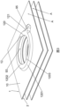
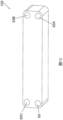
- a plate heat exchanger 100 comprises a plurality of heat exchange plates 1, 2, 3, 4 ( Fig. 17 ) and a port 93 formed in the heat exchange plates 1, 2, 3, 4.
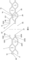
- the plurality of heat exchange plates 1, 2, 3, 4 are arranged in a stacking direction to form a plurality of heat exchange spaces A, B and C ( Fig. 17 ), the plurality of heat exchange plates 1, 2, 3, 4 comprising a plurality of first heat exchange plates 1 and a plurality of second heat exchange plates 2; and the port 93 communicates with a predetermined heat exchange space A of the plurality of heat exchange spaces A, B and C to distribute a heat exchange medium for the predetermined heat exchange space A.
- the plurality of first heat exchange plates 1 and the plurality of second heat exchange plates 2 are alternately arranged in the stacking direction to form alternately arranged first heat exchange spaces A and second heat exchange spaces B.
- the plurality of heat exchange plates 1, 2, 3, 4 comprise a plurality of first heat exchange plates 1, a plurality of second heat exchange plates 2, a plurality of third heat exchange plates 3 and a plurality of fourth heat exchange plates 4, and the first heat exchange plate 1, the second heat exchange plate 2, the third heat exchange plate 3 and the fourth heat exchange plate 4 constitute one repeating unit.
- the plate heat exchanger 100 comprises a plurality of repeating units.
- the plurality of heat exchange spaces A, B and C comprise a first heat exchange space A, a second heat exchange space B and a third heat exchange space C which are separated from each other.
- the first heat exchange plate 1 comprises: a first heat exchange plate main body 10; a first opening 11 formed in the first heat exchange plate main body 10 for forming the port 93; and a first annular protrusion 12 surrounding the first opening 11, adjoining the first opening 11 and protruding from the first heat exchange plate main body 10 toward a first side in the stacking direction.
- the second heat exchange plate 2 comprises: a second heat exchange plate main body 20; a second opening 21 formed in the second heat exchange plate main body 20 for forming the port 93; and a second annular protrusion 22 surrounding the second opening 21, adjoining the second opening 21 and protruding from the second heat exchange plate main body 20 toward a second side opposite to the first side in the stacking direction.
- the sum of heights of the first annular protrusion 12 and the second annular protrusion 22 is equal to a height of the heat exchange space.
- the heights of the first annular protrusion 12 and the second annular protrusion 22 are equal to half of the height of the heat exchange space.
- the plate heat exchanger 100 in addition to the port 93 serving as a first heat exchange medium inlet port, the plate heat exchanger 100 further comprises a first heat exchange medium outlet 93A, a second heat exchange medium inlet 93B, and a second heat exchange medium outlet 93C.
- the plate heat exchanger 100 in addition to the port 93 serving as the first heat exchange medium inlet port, the plate heat exchanger 100 further comprises a first heat exchange medium outlet 93A, a second heat exchange medium inlet 93B, a second heat exchange medium outlet 93C, a third heat exchange medium inlet 93D, and a third heat exchange medium outlet 93E.
- the plurality of heat exchange plates 1, 2, 3, 4 comprise a plurality of first heat exchange plates 1, a plurality of second heat exchange plates 2, a plurality of third heat exchange plates 3 and a plurality of fourth heat exchange plates 4, and the first heat exchange plate 1, the second heat exchange plate 2, the third heat exchange plate 3 and the fourth heat exchange plate 4 constitute one repeating unit.
- the plate heat exchanger 100 may form three loops.
- the first heat exchange space A, the second heat exchange space B and the third heat exchange space C are separated from each other.
- a first heat exchange medium may be a refrigerant
- a second heat exchange medium may be water
- a third heat exchange medium may be a refrigerant.
- the first heat exchange plate 1 and the third heat exchange plate 3 may be the same in the port portion except that one of them has a communicating hole 95 and the other does not have the communicating hole 95.
- the second heat exchange plate 2 and the fourth heat exchange plate 4 may be the same in the port portion. If the communicating hole 95 is formed in one of the second heat exchange plate 2 and the fourth heat exchange plate 4, the first heat exchange plate 1 and the third heat exchange plate 3 may be the same at the port portion.
- the first heat exchange plate 1 and the third heat exchange plate 3 may be the same or different in the heat exchange portion, and the second heat exchange plate 2 and the fourth heat exchange plate 4 may be the same or different in the heat exchange portion.
- the third heat exchange plate 3 may be considered as the first heat exchange plate 1, but has a heat exchange portion that is the same as or different from that of the first heat exchange plate 1, and may or may not have communicating hole 95, regardless of whether the first heat exchange plate 1 has the communicating hole 95 or not.
- the fourth heat exchange plate 4 may be considered as the second heat exchange plate 2, but has a heat exchange portion that is the same as or different from that of the second heat exchange plate 2, and may or may not have the communicating hole 95, regardless of whether the second heat exchange plate 2 has the communicating hole 95 or not.
- the port portion comprises annular portions 14, 24 and portions inside the annular portions 14, 24, and the heat exchange portion is a portion where the heat exchange space is located, and is outside the annular portions 14, 24.
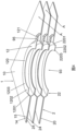
- the first annular protrusion 12 of the first heat exchange plate 1 comprises: an annular first portion 1201 extending from the first heat exchange plate main body 10 toward the first side; and an annular second portion 1202 extending inwardly from the annular first portion 1201, the second portion 1202 of the first annular protrusion 12 having a surface 1203 facing the first side.
- the second annular protrusion 22 of the second heat exchange plate 2 comprises: an annular first portion 2201 extending from the second heat exchange plate main body 20 toward the second side; and an annular second portion 2202 extending inwardly from the annular first portion 2201 of the second annular protrusion 22 of the second heat exchange plate 2, the second portion 2202 of the second annular protrusion 22 having a surface 2203 facing the second side.
- the surface 1203 of the second portion 1202 of the first annular protrusion 12 and the surface 2203 of the second portion 2202 of the second annular protrusion 22 adjacent to each other are in at least partial contact to form a seal over at least one part of a circumferential length of the surface 1203 of the second portion 1202 of the first annular protrusion 12 and the surface 2203 of the second portion 2202 of the second annular protrusion 22.
- a heat exchange medium from the port 93 does not flow into a predetermined heat exchange space A between the entire surface 1203 of the second portion 1202 of the first annular protrusion 12 and the surface 2203 of the second portion 2202 of the second annular protrusion 22, but only flows into the predetermined heat exchange space A through the communicating hole 95.
- the annular first portion 1201 of the first annular protrusion 12 of the first heat exchange plate 1 extends obliquely from the first heat exchange plate main body 10 toward the first side, and the annular second portion 1202 of the first annular protrusion 12 of the first heat exchange plate 1 extends inwardly from the annular first portion 1201 of the first annular protrusion 12 of the first heat exchange plate 1 substantially parallel to the first heat exchange plate main body 10.
- the annular first portion 2201 of the second annular protrusion 22 of the second heat exchange plate 2 extends obliquely from the second heat exchange plate main body 20 toward the second side, and the annular second portion 2202 of the second annular projection 22 of the second heat exchange plate 2 extends inwardly from the annular first portion 2201 of the second annular projection 22 of the second heat exchange plate 2 substantially parallel to the second heat exchange plate main body 20.
- the annular second portion 1202 of the first annular protrusion 12 of the first heat exchange plate 1 adjoins the first opening 11
- the annular second portion 2022 of the second annular protrusion 22 of the second heat exchange plate 2 adjoins the second opening 21.
- the first heat exchange plate 1 further comprises an annular portion 14 surrounding the first annular protrusion 12
- the annular portion 14 of the first heat exchange plate 1 has a surface 15 facing the second side
- the second heat exchange plate 2 further comprises an annular portion 24 surrounding the second annular protrusion 22
- the annular portion 24 of the second heat exchange plate 2 has a surface 25 facing the first side
- the surface 15 of the annular portion 14 of the first heat exchange plate 1 and the surface 25 of the annular portion 24 of the second heat exchange plate 2 adjacent to each other are in at least partial contact to form a seal.
- the heat exchange medium from the port 93 does not flow into other heat exchange spaces B and C other than the predetermined heat exchange space A.
- the plate heat exchanger further comprises a communicating hole 95 formed in at least some of the first heat exchange plates 1 and/or at least some of the second heat exchange plates 2, wherein the port 93 communicates with the predetermined heat exchange space A through the communicating hole 95.
- the communicating hole 95 may have any suitable shape, such as a circular shape, a semi-circular shape, an oval shape, a quadrangular shape or the like.
- projections of the second portion 1202 of the first annular protrusion 12 and the second portion 2202 of the second annular protrusion 22 on a plane perpendicular to the stacking direction have an annular inner overlapping portion (e.g., a radially inner overlapping portion), and a projection of the communicating hole 95 on the plane perpendicular to the stacking direction is outside (e.g., radially outside) the annular inner overlapping portion.
- At least one part of the projection of the second portion 1202 of the first annular protrusion 12 on the plane perpendicular to the stacking direction is outside (e.g., radially outside) the projection of the second portion 2202 of the second annular protrusion 22 on the plane perpendicular to the stacking direction.
- projections of the annular portion 14 of the first heat exchange plate 1 and the annular portion 24 of the second heat exchange plate 2 on the plane perpendicular to the stacking direction have an annular outer overlapping portion (e.g., a radially outer overlapping portion), and the projection of the communicating hole 95 on the plane perpendicular to the stacking direction is inside (e.g., radially inside) the annular outer overlapping portion.
- At least one part of the projection of the annular portion 24 of the second heat exchange plate 2 on the plane perpendicular to the stacking direction is inside (e.g., radially inside) the projection of the annular portion 14 of the first heat exchange plate 1 on the plane perpendicular to the stacking direction.
- the annular portion 14 of the first heat exchange plate 1 has a circular annular shape
- the annular portion 24 of the second heat exchange plate 2 has a circular annular shape
- an inner diameter of the annular portion 24 of the second heat exchange plate 2 is smaller than an inner diameter of the annular portion 14 of the first heat exchange plate 1.
- the annular portion 14 of the first heat exchange plate 1 may adjoin the first portion 1201 of the first annular protrusion 12 of the first heat exchange plate 1, and the annular portion 24 of the second heat exchange plate 2 may adjoin the first portion 2201 of the second annular protrusion 22 of the second heat exchange plate 2.
- the communicating hole 95 is in the annular second portions 1202 of the first annular protrusions 12 of at least some of the first heat exchange plates 1 and/or the communicating hole 95 is in the annular portions 24 of at least some of the second heat exchange plates 2.
- the communicating hole 95 is formed in the first heat exchange plate 1 and/or the second heat exchange plate 2.
- the communicating hole 95 is in the annular first portions 1201 of the first annular protrusions 12 of at least some of the first heat exchange plates 1 and/or the communicating hole 95 is in the annular first portions 2201 of at least some of the second heat exchange plates 2.
- the first annular protrusion 12 and the second annular protrusion 22 may have the same shape and the same size.
- the communicating hole 95 is formed in the first heat exchange plate 1
- the communicating hole 95 may be formed in the second heat exchange plate 2, or the communicating hole 95 may be formed in each of the first heat exchange plate 1and the second heat exchange plate 2.
- one communicating hole 95 is formed in the first heat exchange plate 1
- a plurality of communicating holes 95 may be formed in the first heat exchange plate 1
- a plurality of communicating holes 95 are formed in the second heat exchange plate 2
- a plurality of communicating holes 95 are formed in each of the first heat exchange plate 1 and the second heat exchange plate 2.
- the first annular protrusion 12 of the first heat exchange plate 1 has a circular annular shape
- the second annular protrusion 22 of the second heat exchange plate 2 has a circular annular shape
- an outer diameter of the first annular protrusion 12 of the first heat exchange plate 1 is larger than an outer diameter of the second annular protrusion 22 of the second heat exchange plate 2.
- the first annular protrusion 12 of the first heat exchange plate 1 and the second annular protrusion 22 of the second heat exchange plate 2 may be substantially concentric.
- the first annular protrusion 12 of the first heat exchange plate 1 comprises an annular protrusion main body 120 and a communicating protrusion 121 extending outwardly (e.g., radially outwardly in a direction away from the center of the annular protrusion main body 120) from the annular protrusion main body 120, and at least one part of a projection of the communicating protrusion 121 of the first annular protrusion 12 on the plane perpendicular to the stacking direction is outside (e.g., radially outside) the projection of the second portion 2202 of the second annular projection 22 on the plane perpendicular to the stacking direction, and the projection of the communicating hole 95 on the plane perpendicular to the stacking direction is in the at least one part of the projection of the communicating protrusion 121 of the first annular protrusion 12.
- the communicating hole 95 is formed in the communicating protrusion 121 of the first heat exchange plate 1
- the communicating hole 95 may be formed in the second heat exchange plate 2, or the communicating hole 95 may be formed in each of the communicating protrusion 121 of the first heat exchange plate 1 and the second heat exchange plate 2.
- one communicating hole 95 is formed in the communicating protrusion 121 of the first heat exchange plate 1, a plurality of communicating protrusions 121 may also be provided.
- a plurality of communicating holes 95 are formed in the plurality of communicating protrusions 121 of the first heat exchange plate 1, respectively, or a plurality of communicating holes 95 are formed in the second heat exchange plate 2, or a plurality of communicating holes 95 are formed in each of the plurality of communicating protrusions 121 of the first heat exchange plate 1 and the second heat exchange plate 2.
- the annular protrusion main body 120 of the first annular protrusion 12 of the first heat exchange plate 1 has a circular annular shape
- the second annular protrusion 22 of the second heat exchange plate 2 has a circular annular shape
- an outer diameter of the annular protrusion main body 120 of the first annular protrusion 12 of the first heat exchange plate 1 is substantially equal to an outer diameter of the second annular protrusion 22 of the second heat exchange plate 2.
- the projection of the communicating protrusion 121 of the first annular protrusion 12 on the plane perpendicular to the stacking direction is outside (e.g., radially outside) the projection of the second portion 2202 of the second annular protrusion 22 on the plane perpendicular to the stacking direction, and the projection of the communicating hole 95 on the plane perpendicular to the stacking direction is in the projection of the communicating protrusion 121 of the first annular protrusion 12.
- the communicating hole 95 is a plurality of communicating holes 95
- the communicating protrusion 121 is a plurality of spaced communicating protrusions 121.
- a surface 2203 of the second annular protrusion 22 of the second heat exchange plate 2 facing the second side has a recessed portion 2206, which forms a communicating hole 95.
- the surface 1203 of the first annular protrusion 12 of the first heat exchange plate 1 facing the first side has a recessed portion, which forms the communicating hole 95.
- the surface 1203 of the first annular protrusion 12 of the first heat exchange plate 1 facing the first side has a recessed portion
- the surface 2203 of the second annular protrusion 22 of the second heat exchange plate 2 facing the second side has a recessed portion 2206
- the recessed portion of the surface 1203 of the first annular protrusion 12 of the first heat exchange plate 1 facing the first side and the recessed portion 2206 of the surface 2203 of the second annular protrusion 22 of the second heat exchange plate 2 facing the second side are aligned in the stacking direction to form a communicating hole 95, or are misaligned to form communicating holes 95, respectively.
- an insert with a hole may be placed in the recessed portion to ensure the accuracy of the communicating hole.
- first annular protrusion 12 of the first heat exchange plate 1 has a circular annular shape
- second protrusion of the second heat exchange plate 2 has a circular annular shape
- an outer diameter of the first annular protrusion 12 of the first heat exchange plate 1 is substantially equal to an outer diameter of the second annular protrusion 22 of the second heat exchange plate 2.
- the concepts according to the embodiments of the present invention can be applied to any plate heat exchanger, not limited to the heat exchangers shown in the figures. That is, the port portion of the heat exchange plate of the plate heat exchanger according to the embodiments of the present invention can be applied to any plate heat exchanger.
- the plate heat exchanger according to the embodiments of the present invention can simplify the manufacturing process of the plate heat exchanger, for example.
- a separate distributor may be omitted for the plate heat exchanger.
- the use of the plate heat exchanger according to the embodiments of the present invention can reduce the cost.
- an integrated distributor is formed on the heat exchange plate by means of stamping.
Landscapes
- Engineering & Computer Science (AREA)
- Physics & Mathematics (AREA)
- Thermal Sciences (AREA)
- Mechanical Engineering (AREA)
- General Engineering & Computer Science (AREA)
- Heat-Exchange Devices With Radiators And Conduit Assemblies (AREA)
Applications Claiming Priority (2)
| Application Number | Priority Date | Filing Date | Title |
|---|---|---|---|
| CN202010073885.3A CN113154910A (zh) | 2020-01-22 | 2020-01-22 | 板式换热器 |
| PCT/CN2020/128673 WO2021147479A1 (zh) | 2020-01-22 | 2020-11-13 | 板式换热器 |
Publications (3)
| Publication Number | Publication Date |
|---|---|
| EP4095478A1 EP4095478A1 (en) | 2022-11-30 |
| EP4095478A4 EP4095478A4 (en) | 2024-02-14 |
| EP4095478B1 true EP4095478B1 (en) | 2024-10-30 |
Family
ID=76881758
Family Applications (1)
| Application Number | Title | Priority Date | Filing Date |
|---|---|---|---|
| EP20915546.4A Active EP4095478B1 (en) | 2020-01-22 | 2020-11-13 | Plate heat exchanger |
Country Status (8)
| Country | Link |
|---|---|
| US (1) | US20230062508A1 (pl) |
| EP (1) | EP4095478B1 (pl) |
| CN (1) | CN113154910A (pl) |
| DK (1) | DK4095478T3 (pl) |
| ES (1) | ES3006695T3 (pl) |
| FI (1) | FI4095478T3 (pl) |
| PL (1) | PL4095478T3 (pl) |
| WO (1) | WO2021147479A1 (pl) |
Families Citing this family (2)
| Publication number | Priority date | Publication date | Assignee | Title |
|---|---|---|---|---|
| US11920876B2 (en) * | 2020-12-10 | 2024-03-05 | Danfoss Micro Channel Heat Exchanger (Jiaxing) Co., Ltd. | Distributor for plate heat exchanger and plate heat exchanger |
| CN116817641A (zh) * | 2022-07-08 | 2023-09-29 | 浙江三花板换科技有限公司 | 板式换热器 |
Citations (2)
| Publication number | Priority date | Publication date | Assignee | Title |
|---|---|---|---|---|
| EP1869391B1 (en) * | 2005-04-13 | 2019-06-05 | Alfa Laval Corporate AB | Plate heat exchanger |
| EP3465048B1 (en) * | 2016-05-30 | 2020-03-04 | Alfa Laval Corporate AB | A plate heat exchanger |
Family Cites Families (25)
| Publication number | Priority date | Publication date | Assignee | Title |
|---|---|---|---|---|
| US5462113A (en) * | 1994-06-20 | 1995-10-31 | Flatplate, Inc. | Three-circuit stacked plate heat exchanger |
| SE504799C2 (sv) * | 1995-08-23 | 1997-04-28 | Swep International Ab | Trekrets-värmeväxlare |
| SE512584C2 (sv) * | 1998-07-10 | 2000-04-03 | Lars Persson | Flerkretsvärmeväxlare |
| CN1160535C (zh) * | 1998-10-19 | 2004-08-04 | 株式会社荏原制作所 | 吸收制冷机用溶液热交换器 |
| DE10348803B4 (de) * | 2003-10-21 | 2024-03-14 | Modine Manufacturing Co. | Gehäuseloser Plattenwärmetauscher |
| SE526409C2 (sv) * | 2004-01-09 | 2005-09-06 | Alfa Laval Corp Ab | Plattvärmeväxlare |
| CN2833492Y (zh) * | 2005-10-18 | 2006-11-01 | 高力热处理工业股份有限公司 | 热交换器的流向及流量分配结构 |
| CN100504276C (zh) * | 2007-11-30 | 2009-06-24 | 丹佛斯钦宝(杭州)热交换器有限公司 | 板式换热器介质入口处的均配器 |
| CN101261093B (zh) * | 2008-04-22 | 2010-09-01 | 江苏宝得换热设备有限公司 | 三通道板式换热器 |
| JP5940970B2 (ja) * | 2012-02-10 | 2016-06-29 | 株式会社ティラド | 積層型熱交換器 |
| KR101886075B1 (ko) * | 2012-10-26 | 2018-08-07 | 현대자동차 주식회사 | 차량용 열교환기 |
| ES2725228T3 (es) * | 2012-11-07 | 2019-09-20 | Alfa Laval Corp Ab | Paquete de placas y método de fabricación de un paquete de placas |
| JP5918114B2 (ja) * | 2012-11-30 | 2016-05-18 | 株式会社ティラド | 積層型熱交換器 |
| CN204438867U (zh) * | 2014-12-30 | 2015-07-01 | 浙江峰煌热交换器有限公司 | 一种对角双分配器型板式换热器 |
| MX2018009399A (es) * | 2016-02-03 | 2019-01-10 | Modine Mfg Co | Intercambiador de calor de placas para refrigeración de baterias y conjunto de placas. |
| SE541355C2 (en) * | 2016-12-22 | 2019-08-13 | Alfa Laval Corp Ab | A plate heat exchanger with six ports for three different media |
| CN106767049A (zh) * | 2016-12-28 | 2017-05-31 | 杭州三花家电热管理系统有限公司 | 板式换热器 |
| CN109387111A (zh) * | 2017-08-10 | 2019-02-26 | 丹佛斯微通道换热器(嘉兴)有限公司 | 用于板式换热器的通道的通道件和板式换热器 |
| DE112018004787T5 (de) * | 2017-08-31 | 2020-06-25 | Dana Canada Corporation | Multi-fluid wärmetauscher |
| KR101952938B1 (ko) * | 2017-09-29 | 2019-02-28 | 두성산업(주) | 판형 디스트리뷰터가 구비되는 열교환기 |
| DE102018206574A1 (de) * | 2018-04-27 | 2019-10-31 | Mahle International Gmbh | Stapelscheibenwärmetauscher |
| JP7182395B2 (ja) * | 2018-08-09 | 2022-12-02 | リンナイ株式会社 | 熱交換器 |
| CN112781426B (zh) * | 2019-11-08 | 2023-03-28 | 丹佛斯有限公司 | 用于板式换热器的换热板和板式换热器 |
| CN211575949U (zh) * | 2020-01-22 | 2020-09-25 | 丹佛斯有限公司 | 板式换热器 |
| US11920876B2 (en) * | 2020-12-10 | 2024-03-05 | Danfoss Micro Channel Heat Exchanger (Jiaxing) Co., Ltd. | Distributor for plate heat exchanger and plate heat exchanger |
-
2020
- 2020-01-22 CN CN202010073885.3A patent/CN113154910A/zh active Pending
- 2020-11-13 WO PCT/CN2020/128673 patent/WO2021147479A1/zh not_active Ceased
- 2020-11-13 PL PL20915546.4T patent/PL4095478T3/pl unknown
- 2020-11-13 US US17/793,961 patent/US20230062508A1/en active Pending
- 2020-11-13 ES ES20915546T patent/ES3006695T3/es active Active
- 2020-11-13 DK DK20915546.4T patent/DK4095478T3/da active
- 2020-11-13 EP EP20915546.4A patent/EP4095478B1/en active Active
- 2020-11-13 FI FIEP20915546.4T patent/FI4095478T3/fi active
Patent Citations (2)
| Publication number | Priority date | Publication date | Assignee | Title |
|---|---|---|---|---|
| EP1869391B1 (en) * | 2005-04-13 | 2019-06-05 | Alfa Laval Corporate AB | Plate heat exchanger |
| EP3465048B1 (en) * | 2016-05-30 | 2020-03-04 | Alfa Laval Corporate AB | A plate heat exchanger |
Also Published As
| Publication number | Publication date |
|---|---|
| US20230062508A1 (en) | 2023-03-02 |
| ES3006695T3 (en) | 2025-03-18 |
| PL4095478T3 (pl) | 2025-03-03 |
| DK4095478T3 (da) | 2025-01-02 |
| WO2021147479A1 (zh) | 2021-07-29 |
| FI4095478T3 (fi) | 2025-01-30 |
| EP4095478A4 (en) | 2024-02-14 |
| CN113154910A (zh) | 2021-07-23 |
| EP4095478A1 (en) | 2022-11-30 |
Similar Documents
| Publication | Publication Date | Title |
|---|---|---|
| CN211575949U (zh) | 板式换热器 | |
| US6164371A (en) | Plate heat exchanger for three heat exchanging fluids | |
| EP1062472B1 (en) | Three circuit plate heat exchanger | |
| CN110411248B (zh) | 堆叠板式热交换器 | |
| EP4095478B1 (en) | Plate heat exchanger | |
| US11231210B2 (en) | Stack type heat exchanger | |
| US7690420B2 (en) | Plate heat exchanger | |
| JP2013007516A (ja) | オイルクーラ | |
| US12379165B2 (en) | Heat exchanger plate, and a plate heat exchanger | |
| KR20200025848A (ko) | 판형 열교환기 | |
| EP4012323B1 (en) | Distributor for plate heat exchanger, and plate heat exchanger | |
| KR20010083957A (ko) | 방사류환상열교환기 | |
| EP3467422B1 (en) | Heat exchanger assembly | |
| CN119803129B (zh) | 板式换热器、热管理系统和车辆 | |
| JP2022147760A (ja) | プレート式熱交換器 | |
| EP4474747A1 (en) | A heat exchanger | |
| JP2026013080A (ja) | カッププレート積層型熱交換器 | |
| CA3167538C (en) | A heat exchanger plate, and a plate heat exchanger | |
| JP6929765B2 (ja) | オイルクーラ | |
| JP7057654B2 (ja) | オイルクーラ | |
| EP4053488A1 (en) | Heat exchange plate for use in plate-type heat exchanger, and plate-type heat exchanger | |
| JP6986431B2 (ja) | オイルクーラ | |
| KR20240083475A (ko) | 열교환기 | |
| JP2001027490A (ja) | 自動車のオイルを冷却するためのプレートタイプ熱交換器 |
Legal Events
| Date | Code | Title | Description |
|---|---|---|---|
| STAA | Information on the status of an ep patent application or granted ep patent |
Free format text: STATUS: THE INTERNATIONAL PUBLICATION HAS BEEN MADE |
|
| PUAI | Public reference made under article 153(3) epc to a published international application that has entered the european phase |
Free format text: ORIGINAL CODE: 0009012 |
|
| STAA | Information on the status of an ep patent application or granted ep patent |
Free format text: STATUS: REQUEST FOR EXAMINATION WAS MADE |
|
| 17P | Request for examination filed |
Effective date: 20220726 |
|
| AK | Designated contracting states |
Kind code of ref document: A1 Designated state(s): AL AT BE BG CH CY CZ DE DK EE ES FI FR GB GR HR HU IE IS IT LI LT LU LV MC MK MT NL NO PL PT RO RS SE SI SK SM TR |
|
| DAV | Request for validation of the european patent (deleted) | ||
| DAX | Request for extension of the european patent (deleted) | ||
| P01 | Opt-out of the competence of the unified patent court (upc) registered |
Effective date: 20230713 |
|
| A4 | Supplementary search report drawn up and despatched |
Effective date: 20240112 |
|
| RIC1 | Information provided on ipc code assigned before grant |
Ipc: F28F 9/22 20060101AFI20240108BHEP |
|
| GRAP | Despatch of communication of intention to grant a patent |
Free format text: ORIGINAL CODE: EPIDOSNIGR1 |
|
| STAA | Information on the status of an ep patent application or granted ep patent |
Free format text: STATUS: GRANT OF PATENT IS INTENDED |
|
| INTG | Intention to grant announced |
Effective date: 20240808 |
|
| GRAS | Grant fee paid |
Free format text: ORIGINAL CODE: EPIDOSNIGR3 |
|
| GRAA | (expected) grant |
Free format text: ORIGINAL CODE: 0009210 |
|
| STAA | Information on the status of an ep patent application or granted ep patent |
Free format text: STATUS: THE PATENT HAS BEEN GRANTED |
|
| AK | Designated contracting states |
Kind code of ref document: B1 Designated state(s): AL AT BE BG CH CY CZ DE DK EE ES FI FR GB GR HR HU IE IS IT LI LT LU LV MC MK MT NL NO PL PT RO RS SE SI SK SM TR |
|
| REG | Reference to a national code |
Ref country code: GB Ref legal event code: FG4D |
|
| REG | Reference to a national code |
Ref country code: CH Ref legal event code: EP |
|
| REG | Reference to a national code |
Ref country code: IE Ref legal event code: FG4D |
|
| REG | Reference to a national code |
Ref country code: DE Ref legal event code: R096 Ref document number: 602020040589 Country of ref document: DE |
|
| REG | Reference to a national code |
Ref country code: NL Ref legal event code: FP |
|
| REG | Reference to a national code |
Ref country code: DK Ref legal event code: T3 Effective date: 20241219 Ref country code: SE Ref legal event code: TRGR |
|
| REG | Reference to a national code |
Ref country code: FI Ref legal event code: FGE |
|
| REG | Reference to a national code |
Ref country code: SK Ref legal event code: T3 Ref document number: E 45520 Country of ref document: SK |
|
| REG | Reference to a national code |
Ref country code: LT Ref legal event code: MG9D |
|
| REG | Reference to a national code |
Ref country code: ES Ref legal event code: FG2A Ref document number: 3006695 Country of ref document: ES Kind code of ref document: T3 Effective date: 20250318 |
|
| PG25 | Lapsed in a contracting state [announced via postgrant information from national office to epo] |
Ref country code: HR Free format text: LAPSE BECAUSE OF FAILURE TO SUBMIT A TRANSLATION OF THE DESCRIPTION OR TO PAY THE FEE WITHIN THE PRESCRIBED TIME-LIMIT Effective date: 20241030 Ref country code: PT Free format text: LAPSE BECAUSE OF FAILURE TO SUBMIT A TRANSLATION OF THE DESCRIPTION OR TO PAY THE FEE WITHIN THE PRESCRIBED TIME-LIMIT Effective date: 20250228 Ref country code: IS Free format text: LAPSE BECAUSE OF FAILURE TO SUBMIT A TRANSLATION OF THE DESCRIPTION OR TO PAY THE FEE WITHIN THE PRESCRIBED TIME-LIMIT Effective date: 20250228 |
|
| PG25 | Lapsed in a contracting state [announced via postgrant information from national office to epo] |
Ref country code: BG Free format text: LAPSE BECAUSE OF FAILURE TO SUBMIT A TRANSLATION OF THE DESCRIPTION OR TO PAY THE FEE WITHIN THE PRESCRIBED TIME-LIMIT Effective date: 20241030 |
|
| PG25 | Lapsed in a contracting state [announced via postgrant information from national office to epo] |
Ref country code: NO Free format text: LAPSE BECAUSE OF FAILURE TO SUBMIT A TRANSLATION OF THE DESCRIPTION OR TO PAY THE FEE WITHIN THE PRESCRIBED TIME-LIMIT Effective date: 20250130 |
|
| PG25 | Lapsed in a contracting state [announced via postgrant information from national office to epo] |
Ref country code: LV Free format text: LAPSE BECAUSE OF FAILURE TO SUBMIT A TRANSLATION OF THE DESCRIPTION OR TO PAY THE FEE WITHIN THE PRESCRIBED TIME-LIMIT Effective date: 20241030 Ref country code: GR Free format text: LAPSE BECAUSE OF FAILURE TO SUBMIT A TRANSLATION OF THE DESCRIPTION OR TO PAY THE FEE WITHIN THE PRESCRIBED TIME-LIMIT Effective date: 20250131 |
|
| PG25 | Lapsed in a contracting state [announced via postgrant information from national office to epo] |
Ref country code: RS Free format text: LAPSE BECAUSE OF FAILURE TO SUBMIT A TRANSLATION OF THE DESCRIPTION OR TO PAY THE FEE WITHIN THE PRESCRIBED TIME-LIMIT Effective date: 20250130 |
|
| REG | Reference to a national code |
Ref country code: CH Ref legal event code: PL |
|
| PG25 | Lapsed in a contracting state [announced via postgrant information from national office to epo] |
Ref country code: SM Free format text: LAPSE BECAUSE OF FAILURE TO SUBMIT A TRANSLATION OF THE DESCRIPTION OR TO PAY THE FEE WITHIN THE PRESCRIBED TIME-LIMIT Effective date: 20241030 |
|
| PG25 | Lapsed in a contracting state [announced via postgrant information from national office to epo] |
Ref country code: MC Free format text: LAPSE BECAUSE OF FAILURE TO SUBMIT A TRANSLATION OF THE DESCRIPTION OR TO PAY THE FEE WITHIN THE PRESCRIBED TIME-LIMIT Effective date: 20241030 |
|
| PG25 | Lapsed in a contracting state [announced via postgrant information from national office to epo] |
Ref country code: LU Free format text: LAPSE BECAUSE OF NON-PAYMENT OF DUE FEES Effective date: 20241113 |
|
| REG | Reference to a national code |
Ref country code: CH Ref legal event code: PL |
|
| PG25 | Lapsed in a contracting state [announced via postgrant information from national office to epo] |
Ref country code: EE Free format text: LAPSE BECAUSE OF FAILURE TO SUBMIT A TRANSLATION OF THE DESCRIPTION OR TO PAY THE FEE WITHIN THE PRESCRIBED TIME-LIMIT Effective date: 20241030 |
|
| PG25 | Lapsed in a contracting state [announced via postgrant information from national office to epo] |
Ref country code: CH Free format text: LAPSE BECAUSE OF NON-PAYMENT OF DUE FEES Effective date: 20241130 |
|
| PG25 | Lapsed in a contracting state [announced via postgrant information from national office to epo] |
Ref country code: CZ Free format text: LAPSE BECAUSE OF FAILURE TO SUBMIT A TRANSLATION OF THE DESCRIPTION OR TO PAY THE FEE WITHIN THE PRESCRIBED TIME-LIMIT Effective date: 20241030 |
|
| REG | Reference to a national code |
Ref country code: DE Ref legal event code: R097 Ref document number: 602020040589 Country of ref document: DE |
|
| REG | Reference to a national code |
Ref country code: BE Ref legal event code: MM Effective date: 20241130 |
|
| PLBE | No opposition filed within time limit |
Free format text: ORIGINAL CODE: 0009261 |
|
| STAA | Information on the status of an ep patent application or granted ep patent |
Free format text: STATUS: NO OPPOSITION FILED WITHIN TIME LIMIT |
|
| 26N | No opposition filed |
Effective date: 20250731 |
|
| PG25 | Lapsed in a contracting state [announced via postgrant information from national office to epo] |
Ref country code: BE Free format text: LAPSE BECAUSE OF NON-PAYMENT OF DUE FEES Effective date: 20241130 |
|
| PG25 | Lapsed in a contracting state [announced via postgrant information from national office to epo] |
Ref country code: IE Free format text: LAPSE BECAUSE OF NON-PAYMENT OF DUE FEES Effective date: 20241113 |
|
| PGFP | Annual fee paid to national office [announced via postgrant information from national office to epo] |
Ref country code: NL Payment date: 20251015 Year of fee payment: 6 |
|
| PGFP | Annual fee paid to national office [announced via postgrant information from national office to epo] |
Ref country code: DE Payment date: 20251007 Year of fee payment: 6 |
|
| PGFP | Annual fee paid to national office [announced via postgrant information from national office to epo] |
Ref country code: GB Payment date: 20251016 Year of fee payment: 6 |
|
| PGFP | Annual fee paid to national office [announced via postgrant information from national office to epo] |
Ref country code: AT Payment date: 20251027 Year of fee payment: 6 |
|
| PGFP | Annual fee paid to national office [announced via postgrant information from national office to epo] |
Ref country code: FI Payment date: 20251113 Year of fee payment: 6 Ref country code: DK Payment date: 20251112 Year of fee payment: 6 Ref country code: IT Payment date: 20251022 Year of fee payment: 6 |
|
| PGFP | Annual fee paid to national office [announced via postgrant information from national office to epo] |
Ref country code: FR Payment date: 20251008 Year of fee payment: 6 |
|
| PGFP | Annual fee paid to national office [announced via postgrant information from national office to epo] |
Ref country code: SE Payment date: 20251010 Year of fee payment: 6 |
|
| PGFP | Annual fee paid to national office [announced via postgrant information from national office to epo] |
Ref country code: PL Payment date: 20251014 Year of fee payment: 6 |
|
| PGFP | Annual fee paid to national office [announced via postgrant information from national office to epo] |
Ref country code: SK Payment date: 20251013 Year of fee payment: 6 Ref country code: RO Payment date: 20251027 Year of fee payment: 6 |
|
| PGFP | Annual fee paid to national office [announced via postgrant information from national office to epo] |
Ref country code: ES Payment date: 20251210 Year of fee payment: 6 |