EP3465048B1 - A plate heat exchanger - Google Patents
A plate heat exchanger Download PDFInfo
- Publication number
- EP3465048B1 EP3465048B1 EP17729395.8A EP17729395A EP3465048B1 EP 3465048 B1 EP3465048 B1 EP 3465048B1 EP 17729395 A EP17729395 A EP 17729395A EP 3465048 B1 EP3465048 B1 EP 3465048B1
- Authority
- EP
- European Patent Office
- Prior art keywords
- heat exchanger
- plate
- peripheral rim
- exchanger plates
- inlet channel
- Prior art date
- Legal status (The legal status is an assumption and is not a legal conclusion. Google has not performed a legal analysis and makes no representation as to the accuracy of the status listed.)
- Active
Links
Images

Classifications
-
- F—MECHANICAL ENGINEERING; LIGHTING; HEATING; WEAPONS; BLASTING
- F28—HEAT EXCHANGE IN GENERAL
- F28D—HEAT-EXCHANGE APPARATUS, NOT PROVIDED FOR IN ANOTHER SUBCLASS, IN WHICH THE HEAT-EXCHANGE MEDIA DO NOT COME INTO DIRECT CONTACT
- F28D9/00—Heat-exchange apparatus having stationary plate-like or laminated conduit assemblies for both heat-exchange media, the media being in contact with different sides of a conduit wall
- F28D9/0031—Heat-exchange apparatus having stationary plate-like or laminated conduit assemblies for both heat-exchange media, the media being in contact with different sides of a conduit wall the conduits for one heat-exchange medium being formed by paired plates touching each other
- F28D9/0043—Heat-exchange apparatus having stationary plate-like or laminated conduit assemblies for both heat-exchange media, the media being in contact with different sides of a conduit wall the conduits for one heat-exchange medium being formed by paired plates touching each other the plates having openings therein for circulation of at least one heat-exchange medium from one conduit to another
- F28D9/005—Heat-exchange apparatus having stationary plate-like or laminated conduit assemblies for both heat-exchange media, the media being in contact with different sides of a conduit wall the conduits for one heat-exchange medium being formed by paired plates touching each other the plates having openings therein for circulation of at least one heat-exchange medium from one conduit to another the plates having openings therein for both heat-exchange media
-
- F—MECHANICAL ENGINEERING; LIGHTING; HEATING; WEAPONS; BLASTING
- F28—HEAT EXCHANGE IN GENERAL
- F28F—DETAILS OF HEAT-EXCHANGE AND HEAT-TRANSFER APPARATUS, OF GENERAL APPLICATION
- F28F3/00—Plate-like or laminated elements; Assemblies of plate-like or laminated elements
- F28F3/08—Elements constructed for building-up into stacks, e.g. capable of being taken apart for cleaning
- F28F3/086—Elements constructed for building-up into stacks, e.g. capable of being taken apart for cleaning having one or more openings therein forming tubular heat-exchange passages
-
- F—MECHANICAL ENGINEERING; LIGHTING; HEATING; WEAPONS; BLASTING
- F28—HEAT EXCHANGE IN GENERAL
- F28F—DETAILS OF HEAT-EXCHANGE AND HEAT-TRANSFER APPARATUS, OF GENERAL APPLICATION
- F28F3/00—Plate-like or laminated elements; Assemblies of plate-like or laminated elements
- F28F3/08—Elements constructed for building-up into stacks, e.g. capable of being taken apart for cleaning
- F28F3/10—Arrangements for sealing the margins
-
- F—MECHANICAL ENGINEERING; LIGHTING; HEATING; WEAPONS; BLASTING
- F28—HEAT EXCHANGE IN GENERAL
- F28F—DETAILS OF HEAT-EXCHANGE AND HEAT-TRANSFER APPARATUS, OF GENERAL APPLICATION
- F28F9/00—Casings; Header boxes; Auxiliary supports for elements; Auxiliary members within casings
- F28F9/02—Header boxes; End plates
- F28F9/026—Header boxes; End plates with static flow control means, e.g. with means for uniformly distributing heat exchange media into conduits
- F28F9/027—Header boxes; End plates with static flow control means, e.g. with means for uniformly distributing heat exchange media into conduits in the form of distribution pipes
- F28F9/0273—Header boxes; End plates with static flow control means, e.g. with means for uniformly distributing heat exchange media into conduits in the form of distribution pipes with multiple holes
-
- F—MECHANICAL ENGINEERING; LIGHTING; HEATING; WEAPONS; BLASTING
- F25—REFRIGERATION OR COOLING; COMBINED HEATING AND REFRIGERATION SYSTEMS; HEAT PUMP SYSTEMS; MANUFACTURE OR STORAGE OF ICE; LIQUEFACTION SOLIDIFICATION OF GASES
- F25B—REFRIGERATION MACHINES, PLANTS OR SYSTEMS; COMBINED HEATING AND REFRIGERATION SYSTEMS; HEAT PUMP SYSTEMS
- F25B39/00—Evaporators; Condensers
- F25B39/02—Evaporators
- F25B39/022—Evaporators with plate-like or laminated elements
-
- F—MECHANICAL ENGINEERING; LIGHTING; HEATING; WEAPONS; BLASTING
- F28—HEAT EXCHANGE IN GENERAL
- F28D—HEAT-EXCHANGE APPARATUS, NOT PROVIDED FOR IN ANOTHER SUBCLASS, IN WHICH THE HEAT-EXCHANGE MEDIA DO NOT COME INTO DIRECT CONTACT
- F28D21/00—Heat-exchange apparatus not covered by any of the groups F28D1/00 - F28D20/00
- F28D2021/0019—Other heat exchangers for particular applications; Heat exchange systems not otherwise provided for
- F28D2021/0061—Other heat exchangers for particular applications; Heat exchange systems not otherwise provided for for phase-change applications
- F28D2021/0064—Vaporizers, e.g. evaporators
-
- F—MECHANICAL ENGINEERING; LIGHTING; HEATING; WEAPONS; BLASTING
- F28—HEAT EXCHANGE IN GENERAL
- F28D—HEAT-EXCHANGE APPARATUS, NOT PROVIDED FOR IN ANOTHER SUBCLASS, IN WHICH THE HEAT-EXCHANGE MEDIA DO NOT COME INTO DIRECT CONTACT
- F28D9/00—Heat-exchange apparatus having stationary plate-like or laminated conduit assemblies for both heat-exchange media, the media being in contact with different sides of a conduit wall
- F28D9/0031—Heat-exchange apparatus having stationary plate-like or laminated conduit assemblies for both heat-exchange media, the media being in contact with different sides of a conduit wall the conduits for one heat-exchange medium being formed by paired plates touching each other
- F28D9/0037—Heat-exchange apparatus having stationary plate-like or laminated conduit assemblies for both heat-exchange media, the media being in contact with different sides of a conduit wall the conduits for one heat-exchange medium being formed by paired plates touching each other the conduits for the other heat-exchange medium also being formed by paired plates touching each other
-
- F—MECHANICAL ENGINEERING; LIGHTING; HEATING; WEAPONS; BLASTING
- F28—HEAT EXCHANGE IN GENERAL
- F28F—DETAILS OF HEAT-EXCHANGE AND HEAT-TRANSFER APPARATUS, OF GENERAL APPLICATION
- F28F2250/00—Arrangements for modifying the flow of the heat exchange media, e.g. flow guiding means; Particular flow patterns
- F28F2250/04—Communication passages between channels
-
- F—MECHANICAL ENGINEERING; LIGHTING; HEATING; WEAPONS; BLASTING
- F28—HEAT EXCHANGE IN GENERAL
- F28F—DETAILS OF HEAT-EXCHANGE AND HEAT-TRANSFER APPARATUS, OF GENERAL APPLICATION
- F28F3/00—Plate-like or laminated elements; Assemblies of plate-like or laminated elements
- F28F3/02—Elements or assemblies thereof with means for increasing heat-transfer area, e.g. with fins, with recesses, with corrugations
- F28F3/025—Elements or assemblies thereof with means for increasing heat-transfer area, e.g. with fins, with recesses, with corrugations the means being corrugated, plate-like elements
Definitions
- the present invention refers to a plate heat exchanger for evaporation according to the preamble of claim 1.
- EP-2 730 878 discloses a plate package of a plate heat exchanger.
- the plate package comprises first heat exchanger plates and second heat exchanger plates, which are arranged side by side in such a way that a first plate interspace is formed between each pair of adjacent first heat exchanger plates and second heat exchanger plates, and a second plate interspace between each pair of adjacent second heat exchanger plates and first heat exchanger plates.
- the first plate interspaces and the second plate interspaces are separated from each other and provided side by side in an alternating order in the plate package.
- Each of the first and second heat exchanger plates has a first porthole, surrounded by a peripheral rim.
- the first heat exchanger plates and the second heat exchanger plates are joined to each other via joints of braze material between the first and second heat exchanger plates and arranged in such a way that the peripheral rims together define an inlet channel extending through the plate package.
- a restriction hole is provided through the peripheral rim of the first and/or the second heat exchanger plates and forms a fluid passage allowing a communication between the inlet channel and the first plate interspaces.
- restriction hole is sensible to cracking. This sensibility is due to the relatively low height of the peripheral rim, which means that the restriction hole will be positioned relatively close to the edge of the peripheral rim. Consequently, there will be only a short distance between the restriction hole and the edge of the peripheral rim. This is in particular the case when the pressure depth of the heat exchanger plates is small.
- the object of the present invention is to remedy the problems discussed above.
- it is aimed at a plate heat exchanger being less susceptible to cracks at the inlet channel, in particularly in the peripheral rim forming the inlet channel.
- each of the secondary pairs encloses an inlet chamber adjacent to the peripheral rim, and that the inlet chamber is closed to the second plate interspaces, is open to the inlet channel and communicates with one of the first plate interspaces via at least one nozzle member, comprising one or more restrictions holes, thereby permitting a flow of the first fluid from the inlet channel to the first plate interspaces.
- the nozzle member comprises one or more restriction holes.
- Such restriction hole may be made in advance, before the plate heat exchanger is assembled.
- the one or more restriction holes provide a restriction or throttling of the first fluid passing through the nozzle member. Such restriction or throttling ensures a proper distribution of the first fluid in the first plate interspace. The first fluid may thus flow from the inlet channel into the inlet chamber and then through the nozzle into the first plate interspaces.
- the nozzle member extends through the first heat exchanger plate between the inlet chamber and said one of the first plate interspaces.
- the nozzle may thus be located at a distance from the peripheral rim so that the risk for cracks is avoided.
- the number of restriction holes through the first heat exchanger plate may be one, two, three, four or even more.
- the one or more restriction holes together have a flow area of 1.5 - 2.5 mm 2 .
- each of the inlet chambers is separated from the other inlet chambers of the plate heat exchanger.
- the inlet chamber surrounds the inlet channel.
- the inlet chamber may thus be annular.
- the inlet chamber may alternatively extend along a part of the circumference of the inlet channel.
- each of the first heat exchanger plates comprises an annular flat portion adjacent the peripheral rim.
- the annular flat portion and the peripheral rim may partly enclose the inlet chamber.
- the annular flat portion contributes to strengthen the region close to the peripheral rim.
- the annular flat portion extends substantially in parallel with the extension plane.
- the annular flat portion adjoins a corresponding annular flat portion of the second heat exchanger plate of an adjacent secondary pair.
- the joining of the annular flat portion to the corresponding annular flat portion secures a high strength of the plate heat exchanger around the inlet channel.
- the peripheral rim of the first heat exchanger plate of the secondary pairs comprises a depression forming a surface portion extending away from the inlet channel, wherein an aperture extends through the surface portion and permits said flow of the first fluid from the inlet channel to the first plate interspace.
- the aperture may be located at a greater distance from an edge of the peripheral rim than if it is located directly on the peripheral rim.
- the aperture is thus less susceptible to create cracks in the peripheral rim.
- the first fluid may thus flow from the inlet channel into the depression and through the aperture through the surface, and then further into the first plate interspaces.
- the depression extends from the annular surface and from the peripheral rim.
- the surface portion is partly surrounded by a wall surface, which extends between and connects to the surface portion and the annular flat portion.
- the surface portion is substantially plane.
- the surface portion extends substantially in parallel with the extension plane.
- the peripheral rim of the first heat exchanger plate of the secondary pairs comprises a recess extending from an edge of the peripheral rim, and permitting said flow of the first fluid from the inlet channel to the first plate interspaces.
- Such a recess located at the edge of the peripheral rim is less susceptible to create cracks in the peripheral rim than a hole through the peripheral rim close to the edge.
- the first fluid may thus flow from the inlet channel through the recess into the inlet chamber and then further into the first plate interspace.
- the peripheral rim has a rim height perpendicular to the extension plane from an edge to a root end of the peripheral rim, wherein the peripheral rim passes the adjacent second heat exchanger plate before reaching the adjacent first heat exchanger plate.
- the edge of the peripheral rim may thus be joined to the root end of the peripheral rim of the first heat exchanger plate of the adjacent secondary pair.
- each of the first and second heat exchanger plates has a heat exchanger area comprising a corrugation of ridges and valleys, and wherein a pressure depth is defined between an upper point of the ridges and a lower point of the valleys on an upper side of the heat exchanger plate.
- the pressure depth is less than 3 mm, preferably less than 2 mm.
- each of the first and second heat exchanger plates comprises an edge area extending around the heat exchanger area.
- first heat exchanger plates and the second heat exchanger plates are permanently joined to each other, preferably through brazing.
- Figs 1 and 2 disclose a plate heat exchanger comprising a plurality of heat exchanger plates 1, 2.
- the heat exchanger plates 1, 2 comprise first heat exchanger plates 1 and second heat exchanger plates 2 arranged beside each other in an alternating order in the plate heat exchanger.
- Each of the first heat exchanger plates 1 and the second heat exchanger plates 2 extends in parallel with an extension plane p.
- the first and second heat exchanger plates 1, 2 are arranged side by side in such in a way that first plate interspaces 3 for a first fluid and second plate interspaces 4 for a second medium are formed.
- the plate heat exchanger is configured to be operated as an evaporator, wherein the first plate interspaces 3 are configured to receive the first fluid to be evaporated therein.
- the first fluid may be any suitable refrigerant.
- the second plate interspaces 4 are configured to receive the second fluid for heating the first fluid to be evaporated in the first plate interspaces 3.
- the plate heat exchanger may also be reversed, and is then configured to be operated as a condenser, wherein the first fluid, i.e. the refrigerant, is condensed in the first plate interspaces 3, and the second fluid is conveyed through the second plate interspaces 4 for cooling the first fluid conveyed through the first plate interspaces 3.
- the first fluid i.e. the refrigerant
- Each first plate interspace 3 is formed by a primary pair I, consisting of one of the second heat exchanger plates 2 and an adjacent one of the first heat exchanger plates 1, see Figs 7 and 8 .
- Each second plate interspace 4 is formed by a secondary pair II, consisting of one of the first heat exchanger plates 1 and an adjacent one of the second heat exchanger plates 2, see Figs 7 and 8 .
- the first plate interspaces 3 and the second plate interspaces 4 are provided side by side in an alternating order in the plate heat exchanger, as can be seen in Fig 2 .
- Each first and second heat exchanger plate 1, 2 has a heat exchanger area 5, see Figs 3 and 4 , extending in parallel with the extension plane p, and an edge area 6 extending around the heat exchanger area 5.
- the edge area 6 thus surrounds the heat exchanger area 5 and forms a flange, which is inclined in relation to the extension plane p, see Fig 2 .
- the flange of the edge area 6 of one of the heat exchanger plates 1, 2 adjoins, and is joined to the corresponding flange of the edge area 6 of an adjacent one of the heat exchanger plates 1, 2, in a manner known per se.
- the heat exchanger area 5 comprises a corrugation 7 of ridges and valleys, which is schematically indicated in Figs 3 and 4 , and in Figs 7 and 8 .
- the corrugation 7 may form various patterns, for instance a diagonal pattern, a fishbone pattern, etc. as is known in the art of plate heat exchangers.
- a pressure depth 8 is defined between an upper point of the ridges and a lower point of the valleys on an upper side of the respective first and second heat exchanger plates 1, 2, see Fig 7 .
- the pressure depth 8 is less than 3 mm, preferably less than 2 mm.
- the pressure depth may preferably be equal to or larger than 1 mm.
- Each of the first heat exchanger plates 1 and the second heat exchanger plates 2 also comprises four port holes 11, 12, 13, 14.
- a first port hole 11 of the port holes 11-14 of the first heat exchanger plates 1 is surrounded by a peripheral rim 15, see Figs 7 and 8 .
- the peripheral rim 15 is annular and extends away from the heat exchanger area 5 transversally, or substantially transversally to the extension plane p.
- the peripheral rim 15 has an edge 16 and a root end 17.
- the peripheral rim 15 has a rim height 18 perpendicular to the extension plane p from the edge 16 to the root end 17, see Fig 7 .
- the rim height 18 is larger than or slightly larger than twice the pressure depth 8.
- the peripheral rim 15 is tapering or conical, or slightly tapering or conical, and tapers towards the edge 16, especially from the root end 17 to the edge 16.
- the remaining three port holes 12-14 are not provided with such a peripheral rim, but are defined by a porthole edge, as schematically indicated in Fig 2 for the portholes 13.
- the first port hole 11 of the second heat exchanger plates 2 also lacks the peripheral rim.
- the first port hole 11 of the second heat exchanger plates 2 is defined by a porthole edge 19, see Figs 7 and 8 .
- the first heat exchanger plates 1 and the second heat exchanger plates 2 are permanently joined to each other via joints of braze material, such as copper or a copper alloy, between the first and second heat exchanger plates 1, 2.
- the first and second heat exchanger plates 1, 2 may be made of a metal or a metal alloy, such as stainless steel, which extends to the outer surface of the heat exchanger plate 1, 2.
- the outer surface of the metal or 5 metal alloy has such properties that it adheres to the braze material during the brazing of the plate heat exchanger.
- the heat exchanger plates 1, 2 are arranged in such a way that the peripheral rim 15 of the first heat exchanger plates 1 define an inlet channel 21 extending through the plate heat exchanger, as can be seen in Figs 7 and 8 .
- the peripheral rim 15 passes the adjacent second heat exchanger plate 2 before reaching the adjacent first heat exchanger plate 1.
- the edge 16 of the peripheral rim of the first heat exchanger plate 1 of one secondary pair II is thus joined to the root end 17 of the peripheral rim 15 of the first heat exchanger plate 1 of the adjacent secondary pair II.
- the second port holes 12 of the heat exchanger plates 1, 2 define an outlet channel 22 for the first fluid, see Figs 1 and 2 .
- the third port hole 13 of the heat exchanger plates 1, 2 define an inlet channel 23 for the second fluid.
- the fourth port hole 14 of the heat exchanger plates 1, 2 define an outlet channel 24 for the second fluid.
- the peripheral rim 15 has a convex side, and an opposite concave side.
- the concave side of the peripheral rim 15 faces the inlet channel 21.
- Each of the secondary pairs II encloses a respective inlet chamber 30 adjacent to the peripheral rim 15.
- the convex side of the peripheral rim 15 faces the inlet chamber 30.
- Each of the inlet chambers 30 is closed to the second plate interspaces 4, is open to the inlet channel 21 and communicates with one of the first plate interspaces 3 via a respective nozzle member 31, see Figs 5 and 8 .
- Each of the inlet chambers 30 is thus separated from or closed to the other inlet chambers 30 of the plate heat exchanger.
- a flow of the first fluid from the inlet channel 21 to the first plate interspace 3 via the inlet chamber 30 is permitted.
- the nozzle member 31 extends through the first heat exchanger plate 1 between the inlet chamber 30 and one of the first plate interspaces 3.
- the nozzle member 31 comprises or is formed by one restriction hole. It should be noted that the nozzle member 31 may comprise more than one restriction hole.
- the restriction hole provides a restriction or throttling of the first fluid passing through the nozzle member. Such restriction or throttling ensures a proper distribution of the first fluid in the first plate interspace.
- the restriction hole or more than one restriction holes, together have a flow area of 1.5 - 2.5 mm 2 .
- restriction hole may be circular.
- the inlet chamber 30 surrounds the inlet channel 21.
- the inlet chamber 30 is thus annular.
- Each of the first heat exchanger plates 1 comprises an annular flat portion 32 adjacent the peripheral rim 15.
- the annular flat portion 32 extends from the peripheral rim 15 in parallel with, or substantially in parallel with, the extension plane p.
- Each of the second heat exchanger plates 2 comprises a corresponding annular flat portion 33, which extends from the porthole edge 19 in parallel with, or substantially in parallel with the extension plane p, see Fig 6 .
- the annular flat portion 32 and the corresponding annular flat portion 33 extend in parallel with each other and adjoins each other, see Figs 7 and 8 .
- the annular flat portion 32, the peripheral rim 15, and the corresponding annular flat portion 33 enclose the inlet chamber 30.
- the annular flat portion 32 has a first projection 34 extending away from the peripheral rim 15 in parallel with the extension plane p. At the first projection 3, the annular flat portion 32 is wider.
- the corresponding annular flat portion 33 has a second projection 35.
- the corresponding annular flat portion 33 is wider, and thus extends further from the porthole edge 19.
- the second projection 35 has a longer peripheral length than the first projection 34.
- the first heat exchanger plate 1 of each secondary pair II has a flat area 36, see Fig 5 , which extends in parallel with the extension plane p, see Fig 8 .
- the flat area 36 is located adjacent to a concave part of the plate annular flat portion 32 and extend towards the peripheral rim 15.
- the first projection 34 and the flat area 36 are located opposite to the second projection 35.
- the nozzle member 31 extends through the flat area 36 as can be seen in Figs 5 and 7 .
- annular chamber 30 alternatively may extend only along a part of the circumference of the inlet channel 21.
- the inlet chamber 30 may have a circumferential length corresponding to the length of the second projection 35.
- the peripheral rim 15 of the first heat exchanger plate 1 of the secondary pairs II comprises a depression 40, which forms a surface portion 41 that extends away from the inlet channel 21, see Figs 3 , 5 and 7 .
- the depression 40 extends from the annular flat portion 32 and from the peripheral rim 15.
- the surface portion 41 is partly surrounded by a wall surface 42, which extends between and connects to the surface portion 41 and the annular flat portion 32.
- the surface portion 41 is substantially plane and extends substantially in parallel with the extension plane p.
- the inlet chamber 30, is open to the inlet channel 21 via an aperture 43, see Figs 5 and 7 .
- the aperture 43 extends through the surface portion 41 and permits a flow of the first fluid from the inlet channel 21 to the first plate interspace 3 via the inlet chamber 30.
- the aperture 43 or apertures, have a total flow area that is larger than the flow area of the nozzle member 31, in particular larger than the total flow area of the one or more restriction holes of the nozzle member 31.
- the second embodiment differs from the first embodiment in how the inlet channel 21 is open to the inlet chamber 30. It should be noted that the same reference signs has been used in the different embodiments for corresponding elements.
- the peripheral rim 15 of the first heat exchanger plate 1 of the secondary pairs II comprises a recess 50.
- the recess 50 is open towards and extends from the edge 16 of the peripheral rim 15, see in particular Figs 11 and 12 .
- the inlet chamber 30, is thus open to the inlet channel 21 via the recess 50, which permits a flow of the first fluid from the inlet channel 21 to the first plate interspace 3 via the inlet chamber 30 and the nozzle member 31, which extends through the flat area 36 of the first heat exchanger plate 1.
- the recess 50 is located opposite to the first projection 34 of the annular flat portion 32, as can be seen in Fig 12 .
- the recess 50 have a total flow area that is larger than the flow area of the nozzle member 31, in particular larger than the total flow area of the one or more restriction holes of the nozzle member 31.
- peripheral rim 15 has no depression forming a surface portion.
Description
- The present invention refers to a plate heat exchanger for evaporation according to the preamble of
claim 1. -
EP-2 730 878 discloses a plate package of a plate heat exchanger. The plate package comprises first heat exchanger plates and second heat exchanger plates, which are arranged side by side in such a way that a first plate interspace is formed between each pair of adjacent first heat exchanger plates and second heat exchanger plates, and a second plate interspace between each pair of adjacent second heat exchanger plates and first heat exchanger plates. The first plate interspaces and the second plate interspaces are separated from each other and provided side by side in an alternating order in the plate package. Each of the first and second heat exchanger plates has a first porthole, surrounded by a peripheral rim. The first heat exchanger plates and the second heat exchanger plates are joined to each other via joints of braze material between the first and second heat exchanger plates and arranged in such a way that the peripheral rims together define an inlet channel extending through the plate package. - A restriction hole is provided through the peripheral rim of the first and/or the second heat exchanger plates and forms a fluid passage allowing a communication between the inlet channel and the first plate interspaces.
- One problem related to the prior art plate heat exchanger is that the restriction hole is sensible to cracking. This sensibility is due to the relatively low height of the peripheral rim, which means that the restriction hole will be positioned relatively close to the edge of the peripheral rim. Consequently, there will be only a short distance between the restriction hole and the edge of the peripheral rim. This is in particular the case when the pressure depth of the heat exchanger plates is small.
- The object of the present invention is to remedy the problems discussed above. In particular, it is aimed at a plate heat exchanger being less susceptible to cracks at the inlet channel, in particularly in the peripheral rim forming the inlet channel.
- This object is achieved by the plate heat exchanger initially defined, which is characterized in that each of the secondary pairs encloses an inlet chamber adjacent to the peripheral rim, and that the inlet chamber is closed to the second plate interspaces, is open to the inlet channel and communicates with one of the first plate interspaces via at least one nozzle member, comprising one or more restrictions holes, thereby permitting a flow of the first fluid from the inlet channel to the first plate interspaces.
- By locating the nozzle for the first fluid in the inlet chamber and not through the peripheral rim, cracking of the peripheral rim can be avoided. The nozzle member comprises one or more restriction holes. Such restriction hole may be made in advance, before the plate heat exchanger is assembled. The one or more restriction holes provide a restriction or throttling of the first fluid passing through the nozzle member. Such restriction or throttling ensures a proper distribution of the first fluid in the first plate interspace. The first fluid may thus flow from the inlet channel into the inlet chamber and then through the nozzle into the first plate interspaces.
- According to an embodiment of the invention, the nozzle member extends through the first heat exchanger plate between the inlet chamber and said one of the first plate interspaces. The nozzle may thus be located at a distance from the peripheral rim so that the risk for cracks is avoided.
- According to an embodiment of the invention, the number of restriction holes through the first heat exchanger plate may be one, two, three, four or even more.
- According to an embodiment of the invention, the one or more restriction holes together have a flow area of 1.5 - 2.5 mm2.
- According to an embodiment of the invention, each of the inlet chambers is separated from the other inlet chambers of the plate heat exchanger.
- According to an embodiment of the invention, the inlet chamber surrounds the inlet channel. The inlet chamber may thus be annular. The inlet chamber may alternatively extend along a part of the circumference of the inlet channel.
- According to an embodiment of the invention, each of the first heat exchanger plates comprises an annular flat portion adjacent the peripheral rim. The annular flat portion and the peripheral rim may partly enclose the inlet chamber. The annular flat portion contributes to strengthen the region close to the peripheral rim.
- According to an embodiment of the invention, the annular flat portion extends substantially in parallel with the extension plane.
- According to an embodiment of the invention, the annular flat portion adjoins a corresponding annular flat portion of the second heat exchanger plate of an adjacent secondary pair. The joining of the annular flat portion to the corresponding annular flat portion secures a high strength of the plate heat exchanger around the inlet channel.
- According to an embodiment of the invention, the peripheral rim of the first heat exchanger plate of the secondary pairs comprises a depression forming a surface portion extending away from the inlet channel, wherein an aperture extends through the surface portion and permits said flow of the first fluid from the inlet channel to the first plate interspace.
- By providing an aperture through such a surface portion, the aperture may be located at a greater distance from an edge of the peripheral rim than if it is located directly on the peripheral rim. The aperture is thus less susceptible to create cracks in the peripheral rim. The first fluid may thus flow from the inlet channel into the depression and through the aperture through the surface, and then further into the first plate interspaces.
- According to an embodiment of the invention, the depression extends from the annular surface and from the peripheral rim.
- According to an embodiment of the invention, the surface portion is partly surrounded by a wall surface, which extends between and connects to the surface portion and the annular flat portion.
- According to an embodiment of the invention, the surface portion is substantially plane.
- According to an embodiment of the invention, the surface portion extends substantially in parallel with the extension plane.
- According to an embodiment of the invention, the peripheral rim of the first heat exchanger plate of the secondary pairs comprises a recess extending from an edge of the peripheral rim, and permitting said flow of the first fluid from the inlet channel to the first plate interspaces.
- Such a recess located at the edge of the peripheral rim is less susceptible to create cracks in the peripheral rim than a hole through the peripheral rim close to the edge. The first fluid may thus flow from the inlet channel through the recess into the inlet chamber and then further into the first plate interspace.
- According to an embodiment of the invention, the peripheral rim has a rim height perpendicular to the extension plane from an edge to a root end of the peripheral rim, wherein the peripheral rim passes the adjacent second heat exchanger plate before reaching the adjacent first heat exchanger plate. The edge of the peripheral rim may thus be joined to the root end of the peripheral rim of the first heat exchanger plate of the adjacent secondary pair.
- According to an embodiment of the invention, each of the first and second heat exchanger plates has a heat exchanger area comprising a corrugation of ridges and valleys, and wherein a pressure depth is defined between an upper point of the ridges and a lower point of the valleys on an upper side of the heat exchanger plate.
- According to an embodiment of the invention, the pressure depth is less than 3 mm, preferably less than 2 mm.
- According to an embodiment of the invention, each of the first and second heat exchanger plates comprises an edge area extending around the heat exchanger area.
- According to any one of the preceding claims, wherein the first heat exchanger plates and the second heat exchanger plates are permanently joined to each other, preferably through brazing.
- The present invention is now to be explained more closely through a description of various embodiments and with reference to the drawings attached hereto.
-
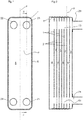
Fig 1 discloses schematically a plan view of a plate heat exchanger according to a first embodiment of the invention. -
Fig 2 discloses schematically a longitudinal sectional view along the line II-II inFig 1 . -
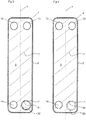
Fig 3 discloses schematically a plan view of a first heat exchanger plate of the plate heat exchanger inFig 1 . -
Fig 4 discloses schematically a plan view of a second heat exchanger plate of the plate heat exchanger inFig 1 . -
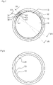
Fig 5 discloses schematically a plan view of an inlet channel area of the first heat exchanger plate. -
Fig 6 discloses schematically a plan view of an inlet channel area of the second heat exchanger plate. -
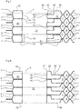
Fig 7 discloses schematically a sectional view of the inlet channel area of some of the heat exchanger plates along the line VII-VII inFig 5 . -
Fig 8 discloses schematically a sectional view of the inlet channel area of some of the heat exchanger plates along the line VIII-VIII inFig 5 . -
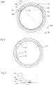
Fig 9 discloses schematically a plan view of the inlet channel area of the first heat exchanger plate of a plate heat exchanger according to a second embodiment. -
Fig 10 discloses schematically a sectional view of an inlet channel area of the second heat exchanger plate. -
Fig 11 discloses schematically a front view of a secondary pair of heat exchanger plates seen from the inlet channel inFig 9 . -
Fig 12 discloses schematically a sectional view of the inlet channel area of some of the heat exchanger plates along the line XII-XII inFig 9 . -
Fig 13 discloses schematically a sectional view of the inlet channel area of some of the heat exchanger plates along the line XIII-XIII inFig 10 . -
Figs 1 and 2 disclose a plate heat exchanger comprising a plurality ofheat exchanger plates heat exchanger plates heat exchanger plates 1 and secondheat exchanger plates 2 arranged beside each other in an alternating order in the plate heat exchanger. - Each of the first
heat exchanger plates 1 and the secondheat exchanger plates 2 extends in parallel with an extension plane p. - The first and second
heat exchanger plates - The plate heat exchanger is configured to be operated as an evaporator, wherein the first plate interspaces 3 are configured to receive the first fluid to be evaporated therein. The first fluid may be any suitable refrigerant. The second plate interspaces 4 are configured to receive the second fluid for heating the first fluid to be evaporated in the first plate interspaces 3.
- The plate heat exchanger may also be reversed, and is then configured to be operated as a condenser, wherein the first fluid, i.e. the refrigerant, is condensed in the first plate interspaces 3, and the second fluid is conveyed through the second plate interspaces 4 for cooling the first fluid conveyed through the first plate interspaces 3.
- Each
first plate interspace 3 is formed by a primary pair I, consisting of one of the secondheat exchanger plates 2 and an adjacent one of the firstheat exchanger plates 1, seeFigs 7 and 8 . - Each
second plate interspace 4 is formed by a secondary pair II, consisting of one of the firstheat exchanger plates 1 and an adjacent one of the secondheat exchanger plates 2, seeFigs 7 and 8 . - The first plate interspaces 3 and the second plate interspaces 4 are provided side by side in an alternating order in the plate heat exchanger, as can be seen in
Fig 2 . - Each first and second
heat exchanger plate heat exchanger area 5, seeFigs 3 and 4 , extending in parallel with the extension plane p, and anedge area 6 extending around theheat exchanger area 5. Theedge area 6 thus surrounds theheat exchanger area 5 and forms a flange, which is inclined in relation to the extension plane p, seeFig 2 . The flange of theedge area 6 of one of theheat exchanger plates edge area 6 of an adjacent one of theheat exchanger plates - The
heat exchanger area 5 comprises acorrugation 7 of ridges and valleys, which is schematically indicated inFigs 3 and 4 , and inFigs 7 and 8 . Thecorrugation 7 may form various patterns, for instance a diagonal pattern, a fishbone pattern, etc. as is known in the art of plate heat exchangers. - A
pressure depth 8 is defined between an upper point of the ridges and a lower point of the valleys on an upper side of the respective first and secondheat exchanger plates Fig 7 . Thepressure depth 8 is less than 3 mm, preferably less than 2 mm. The pressure depth may preferably be equal to or larger than 1 mm. - Each of the first
heat exchanger plates 1 and the secondheat exchanger plates 2 also comprises fourport holes - A
first port hole 11 of the port holes 11-14 of the firstheat exchanger plates 1 is surrounded by aperipheral rim 15, seeFigs 7 and 8 . Theperipheral rim 15 is annular and extends away from theheat exchanger area 5 transversally, or substantially transversally to the extension plane p. - The
peripheral rim 15 has anedge 16 and aroot end 17. Theperipheral rim 15 has arim height 18 perpendicular to the extension plane p from theedge 16 to theroot end 17, seeFig 7 . Therim height 18 is larger than or slightly larger than twice thepressure depth 8. - As can be seen in
Figs 7 and 8 , theperipheral rim 15 is tapering or conical, or slightly tapering or conical, and tapers towards theedge 16, especially from theroot end 17 to theedge 16. - The remaining three port holes 12-14 are not provided with such a peripheral rim, but are defined by a porthole edge, as schematically indicated in
Fig 2 for theportholes 13. - In the embodiments disclosed, the
first port hole 11 of the secondheat exchanger plates 2 also lacks the peripheral rim. Thefirst port hole 11 of the secondheat exchanger plates 2 is defined by aporthole edge 19, seeFigs 7 and 8 . - The first
heat exchanger plates 1 and the secondheat exchanger plates 2 are permanently joined to each other via joints of braze material, such as copper or a copper alloy, between the first and secondheat exchanger plates - The first and second
heat exchanger plates heat exchanger plate - The
heat exchanger plates peripheral rim 15 of the firstheat exchanger plates 1 define aninlet channel 21 extending through the plate heat exchanger, as can be seen inFigs 7 and 8 . Theperipheral rim 15 passes the adjacent secondheat exchanger plate 2 before reaching the adjacent firstheat exchanger plate 1. Theedge 16 of the peripheral rim of the firstheat exchanger plate 1 of one secondary pair II is thus joined to theroot end 17 of theperipheral rim 15 of the firstheat exchanger plate 1 of the adjacent secondary pair II. - The second port holes 12 of the
heat exchanger plates outlet channel 22 for the first fluid, seeFigs 1 and 2 . Thethird port hole 13 of theheat exchanger plates inlet channel 23 for the second fluid. Thefourth port hole 14 of theheat exchanger plates outlet channel 24 for the second fluid. - The
peripheral rim 15 has a convex side, and an opposite concave side. The concave side of theperipheral rim 15 faces theinlet channel 21. - Each of the secondary pairs II encloses a
respective inlet chamber 30 adjacent to theperipheral rim 15. The convex side of theperipheral rim 15 faces theinlet chamber 30. - Each of the
inlet chambers 30 is closed to the second plate interspaces 4, is open to theinlet channel 21 and communicates with one of the first plate interspaces 3 via arespective nozzle member 31, seeFigs 5 and8 . - Each of the
inlet chambers 30 is thus separated from or closed to theother inlet chambers 30 of the plate heat exchanger. - A flow of the first fluid from the
inlet channel 21 to thefirst plate interspace 3 via theinlet chamber 30 is permitted. - The
nozzle member 31 extends through the firstheat exchanger plate 1 between theinlet chamber 30 and one of the first plate interspaces 3. - In the embodiments disclosed, the
nozzle member 31 comprises or is formed by one restriction hole. It should be noted that thenozzle member 31 may comprise more than one restriction hole. The restriction hole provides a restriction or throttling of the first fluid passing through the nozzle member. Such restriction or throttling ensures a proper distribution of the first fluid in the first plate interspace. - The restriction hole, or more than one restriction holes, together have a flow area of 1.5 - 2.5 mm2.
- The restriction hole, or restriction holes, may be circular.
- In the embodiments disclosed, the
inlet chamber 30 surrounds theinlet channel 21. Theinlet chamber 30 is thus annular. - Each of the first
heat exchanger plates 1 comprises an annularflat portion 32 adjacent theperipheral rim 15. The annularflat portion 32 extends from theperipheral rim 15 in parallel with, or substantially in parallel with, the extension plane p. - Each of the second
heat exchanger plates 2 comprises a corresponding annularflat portion 33, which extends from theporthole edge 19 in parallel with, or substantially in parallel with the extension plane p, seeFig 6 . - The annular
flat portion 32 and the corresponding annularflat portion 33 extend in parallel with each other and adjoins each other, seeFigs 7 and 8 . The annularflat portion 32, theperipheral rim 15, and the corresponding annularflat portion 33 enclose theinlet chamber 30. - As can be seen in
Fig 5 , the annularflat portion 32 has afirst projection 34 extending away from theperipheral rim 15 in parallel with the extension plane p. At thefirst projection 3, the annularflat portion 32 is wider. - As can be seen in
Fig 6 , the corresponding annularflat portion 33 has asecond projection 35. At thesecond projection 35, the corresponding annularflat portion 33 is wider, and thus extends further from theporthole edge 19. Thesecond projection 35 has a longer peripheral length than thefirst projection 34. - Beside the
first projection 34, the firstheat exchanger plate 1 of each secondary pair II has aflat area 36, seeFig 5 , which extends in parallel with the extension plane p, seeFig 8 . - The
flat area 36 is located adjacent to a concave part of the plate annularflat portion 32 and extend towards theperipheral rim 15. - The
first projection 34 and theflat area 36 are located opposite to thesecond projection 35. Thenozzle member 31 extends through theflat area 36 as can be seen inFigs 5 and7 . - It should be noted that the
annular chamber 30 alternatively may extend only along a part of the circumference of theinlet channel 21. For instance, theinlet chamber 30 may have a circumferential length corresponding to the length of thesecond projection 35. - In the first embodiment, the
peripheral rim 15 of the firstheat exchanger plate 1 of the secondary pairs II comprises adepression 40, which forms asurface portion 41 that extends away from theinlet channel 21, seeFigs 3 ,5 and7 . Thedepression 40 extends from the annularflat portion 32 and from theperipheral rim 15. Thesurface portion 41 is partly surrounded by awall surface 42, which extends between and connects to thesurface portion 41 and the annularflat portion 32. - The
surface portion 41 is substantially plane and extends substantially in parallel with the extension plane p. - In the first embodiment, the
inlet chamber 30, is open to theinlet channel 21 via anaperture 43, seeFigs 5 and7 . Theaperture 43 extends through thesurface portion 41 and permits a flow of the first fluid from theinlet channel 21 to thefirst plate interspace 3 via theinlet chamber 30. - Although only one
aperture 43 is disclosed in the first embodiment, it should be noted that more than oneapertures 43 may be provided. Theaperture 43, or apertures, have a total flow area that is larger than the flow area of thenozzle member 31, in particular larger than the total flow area of the one or more restriction holes of thenozzle member 31. - The second embodiment, see
Figs 9 to 13 , differs from the first embodiment in how theinlet channel 21 is open to theinlet chamber 30. It should be noted that the same reference signs has been used in the different embodiments for corresponding elements. - In the second embodiment, the
peripheral rim 15 of the firstheat exchanger plate 1 of the secondary pairs II comprises arecess 50. Therecess 50 is open towards and extends from theedge 16 of theperipheral rim 15, see in particularFigs 11 and12 . - In the second embodiment, the
inlet chamber 30, is thus open to theinlet channel 21 via therecess 50, which permits a flow of the first fluid from theinlet channel 21 to thefirst plate interspace 3 via theinlet chamber 30 and thenozzle member 31, which extends through theflat area 36 of the firstheat exchanger plate 1. - The
recess 50 is located opposite to thefirst projection 34 of the annularflat portion 32, as can be seen inFig 12 . - Although only one
recess 50 is disclosed in the second embodiment, it should be noted that more than one recesses 50 may be provided. Therecess 50, or recesses, have a total flow area that is larger than the flow area of thenozzle member 31, in particular larger than the total flow area of the one or more restriction holes of thenozzle member 31. - In the second embodiment,
peripheral rim 15 has no depression forming a surface portion. - The invention is not limited to the embodiments disclosed, but may be varied and modified within the scope of the following claims.
Claims (15)
- A plate heat exchanger for evaporation, comprising first heat exchanger plates (1) and second heat exchanger plates (2) arranged beside each other in an alternating order,
first plate interspaces (3) for a first fluid to be evaporated, each first plate interspace (3) being formed by a primary pair (I) consisting of one of the second heat exchanger plates (2) and an adjacent one of the first heat exchanger plates (1), and
second plate interspaces (4) for a second fluid, each second plate interspace (4) being formed by a secondary pair (II) consisting of one of the first heat exchanger plates (1) and an adjacent one of the second heat exchanger plates (2),
wherein the first and second plate interspaces (3, 4) are arranged beside each other in an alternating order,
wherein each of the first heat exchanger plates (1) and the second heat exchanger plates (2) extends in parallel with an extension plane (p) and comprises a number of portholes (11-14),
wherein each of the first heat exchanger plates (1) comprises a peripheral rim (15) surrounding a first porthole (11) of said number of portholes (11-14) and extending transversely to the extension plane (p),
wherein the peripheral rim (15) of one of the first heat exchanger plates (1) extends to an adjacent one of the first heat exchanger plates (1) so that the peripheral rims (15) define an inlet channel (21) for the first fluid through the plate heat exchanger,
characterized in that each of the secondary pairs (II) encloses an inlet chamber (30) adjacent to the peripheral rim (15), and that the inlet chamber (30) is closed to the second plate interspaces (4), is open to the inlet channel (21) and communicates with one of the first plate interspaces (3) via a nozzle member (31), comprising one or more restrictions holes, thereby permitting a flow of the first fluid from the inlet channel (21) to the first plate interspace (3). - A plate heat exchanger according to claim 1, wherein the nozzle member (31) extends through the first heat exchanger plate (1) between the inlet chamber (30) and said one of the first plate interspaces (3).
- A plate heat exchanger according to any one of claims 1 and 2, wherein the one or more restriction holes together have a flow area of 1.5 - 2.5 mm2.
- A plate heat exchanger according to any one of the preceding claims, wherein the inlet chamber (30) surrounds the inlet channel (21).
- A plate heat exchanger according to claim 4, wherein each of the first heat exchanger plates (1) comprises an annular flat portion (32) adjacent the peripheral rim (15).
- A plate heat exchanger according to claim 5, wherein the annular flat portion (32) extends substantially in parallel with the extension plane (p).
- A plate heat exchanger according to any one of the preceding claims, wherein the peripheral rim (15) of the first heat exchanger plate (1) of the secondary pairs (II) comprises a depression (40) forming a surface portion (41) extending away from the inlet channel (21), and wherein an aperture (43) extends through the surface portion (41) and permits said flow of the first fluid from the inlet channel (21) to the first plate interspace (3).
- A plate heat exchanger according to claim 5 and to claim 7, wherein the depression (40) extends from the annular flat portion (32) and from the peripheral rim (15).
- A plate heat exchanger according to claim 8, wherein the surface portion (41) is partly surrounded by a wall surface (42), which extends between and connects to the surface portion (41) and the annular flat portion (32).
- A plate heat exchanger according to any one of claims 7 to 9, wherein the surface portion (41) is substantially plane.
- A plate heat exchanger according to any one of claims 7 to 10, wherein the surface portion (41) extends substantially in parallel with the extension plane (p).
- A plate heat exchanger according to any one of claims 1 to 6, wherein the peripheral rim (15) of the first heat exchanger plate (1) of the secondary pairs (II) comprises a recess (50) extending from an edge (16) of the peripheral rim (15), and permitting said flow of the first fluid from the inlet channel (21) to the first plate interspaces (3).
- A plate heat exchanger according to any one of the preceding claims, wherein the peripheral rim (15) has a rim height (18) perpendicular to the extension plane (p) from an edge (16) to a root end (17) of the peripheral rim (15), and wherein the peripheral rim (15) passes the adjacent second heat exchanger plate (2) before reaching the adjacent first heat exchanger plate (1).
- A plate heat exchanger according to any one of the preceding claims, wherein each of the first and second heat exchanger plates (1, 2) has a heat exchanger area (5) comprising a corrugation (7) of ridges and valleys, and wherein a pressure depth (8) is defined between an upper point of the ridges and a lower point of the valleys on an upper side of the respective first and second heat exchanger plates (1, 2).
- A plate heat exchange according to claim 14, wherein the pressure depth (8) is less than 3 mm.
Applications Claiming Priority (2)
| Application Number | Priority Date | Filing Date | Title |
|---|---|---|---|
| SE1650749A SE541284C2 (en) | 2016-05-30 | 2016-05-30 | A plate heat exchanger |
| PCT/EP2017/062012 WO2017207292A1 (en) | 2016-05-30 | 2017-05-18 | A plate heat exchanger |
Publications (2)
| Publication Number | Publication Date |
|---|---|
| EP3465048A1 EP3465048A1 (en) | 2019-04-10 |
| EP3465048B1 true EP3465048B1 (en) | 2020-03-04 |
Family
ID=59054081
Family Applications (1)
| Application Number | Title | Priority Date | Filing Date |
|---|---|---|---|
| EP17729395.8A Active EP3465048B1 (en) | 2016-05-30 | 2017-05-18 | A plate heat exchanger |
Country Status (8)
| Country | Link |
|---|---|
| US (1) | US10837710B2 (en) |
| EP (1) | EP3465048B1 (en) |
| JP (1) | JP6763974B2 (en) |
| KR (1) | KR102153402B1 (en) |
| CN (1) | CN109154475B (en) |
| SE (1) | SE541284C2 (en) |
| TW (1) | TWI624642B (en) |
| WO (1) | WO2017207292A1 (en) |
Families Citing this family (7)
| Publication number | Priority date | Publication date | Assignee | Title |
|---|---|---|---|---|
| SE541284C2 (en) * | 2016-05-30 | 2019-06-11 | Alfa Laval Corp Ab | A plate heat exchanger |
| SE543419C2 (en) | 2019-02-26 | 2021-01-12 | Alfa Laval Corp Ab | A heat exchanger plate and a plate heat exchanger |
| CN112747613B (en) * | 2019-10-31 | 2023-06-13 | 丹佛斯有限公司 | Heat exchange plate for plate heat exchanger and plate heat exchanger |
| CN113154910A (en) * | 2020-01-22 | 2021-07-23 | 丹佛斯有限公司 | Plate heat exchanger |
| US11920876B2 (en) * | 2020-12-10 | 2024-03-05 | Danfoss Micro Channel Heat Exchanger (Jiaxing) Co., Ltd. | Distributor for plate heat exchanger and plate heat exchanger |
| SE2150186A1 (en) * | 2021-02-22 | 2022-08-23 | Swep Int Ab | A brazed plate heat exchanger |
| EP4095472A1 (en) * | 2021-05-27 | 2022-11-30 | Danfoss A/S | A plate kind heat exchanger with sealed inlet channel |
Citations (9)
| Publication number | Priority date | Publication date | Assignee | Title |
|---|---|---|---|---|
| GB134277A (en) | 1918-10-24 | 1919-10-24 | John Melville James | Improvements in or relating to Radiators for Cooling Fluids. |
| EP0857287B1 (en) | 1995-10-24 | 2003-02-19 | ALFA LAVAL Corporate AB | Plate heat exchanger |
| WO2005066572A1 (en) | 2004-01-09 | 2005-07-21 | Alfa Laval Corporate Ab | A plate heat exchanger |
| WO2006110090A1 (en) | 2005-04-13 | 2006-10-19 | Alfa Laval Corporate Ab | Plate heat exchanger |
| US20070261834A1 (en) | 2006-05-09 | 2007-11-15 | Kaori Heat Treatment Co., Ltd. | Heat exchanger having uneven flowing paths |
| CN101476831A (en) | 2009-01-22 | 2009-07-08 | 辛娟姣 | Spill hole type throttle structure of plate heat exchanger medium entrance |
| CN101476830A (en) | 2009-01-22 | 2009-07-08 | 辛娟姣 | Slit type throttle structure of plate heat exchanger medium entrance |
| WO2010069872A1 (en) | 2008-12-17 | 2010-06-24 | Swep International Ab | Port opening of heat exchanger |
| EP2730878A1 (en) | 2012-11-07 | 2014-05-14 | Alfa Laval Corporate AB | Plate package and method of making a plate package |
Family Cites Families (34)
| Publication number | Priority date | Publication date | Assignee | Title |
|---|---|---|---|---|
| US2392444A (en) * | 1940-05-09 | 1946-01-08 | Gen Aircraft Equipment Inc | Heat exchange device |
| FR958699A (en) * | 1942-05-22 | 1950-03-17 | ||
| US2550339A (en) * | 1948-08-03 | 1951-04-24 | York Corp | Plate type heat exchanger |
| US3537165A (en) * | 1968-06-26 | 1970-11-03 | Air Preheater | Method of making a plate-type heat exchanger |
| SE423750B (en) * | 1977-01-14 | 1982-05-24 | Munters Ab Carl | DEVICE EXCHANGER FOR SENSIBLE AND / OR LATENT TRANSMISSION |
| FR2433156A1 (en) * | 1978-08-09 | 1980-03-07 | Commissariat Energie Atomique | IMPROVEMENT IN PLATE HEAT EXCHANGERS |
| US4327802A (en) * | 1979-06-18 | 1982-05-04 | Borg-Warner Corporation | Multiple fluid heat exchanger |
| AT380739B (en) * | 1984-03-14 | 1986-06-25 | Helmut Ing Fischer | DISASSEMBLABLE PLATE HEAT EXCHANGER AND PRESS TOOL FOR THE PRODUCTION OF HEAT EXCHANGE PLATES OF THIS HEAT EXCHANGER |
| US4872578A (en) * | 1988-06-20 | 1989-10-10 | Itt Standard Of Itt Corporation | Plate type heat exchanger |
| SE502984C2 (en) * | 1993-06-17 | 1996-03-04 | Alfa Laval Thermal Ab | Flat heat exchanger with specially designed door sections |
| DE19511991C2 (en) * | 1995-03-31 | 2002-06-13 | Behr Gmbh & Co | Plate heat exchanger |
| DE19722074A1 (en) * | 1997-05-27 | 1998-12-03 | Knecht Filterwerke Gmbh | Plate heat exchangers, in particular oil / coolant coolers for motor vehicles |
| US20010030043A1 (en) * | 1999-05-11 | 2001-10-18 | William T. Gleisle | Brazed plate heat exchanger utilizing metal gaskets and method for making same |
| DE19939264B4 (en) * | 1999-08-19 | 2005-08-18 | Behr Gmbh & Co. Kg | Plate heat exchangers |
| JP4454779B2 (en) | 2000-03-31 | 2010-04-21 | 株式会社日阪製作所 | Plate heat exchanger |
| DE10024888B4 (en) | 2000-05-16 | 2008-10-16 | Gea Wtt Gmbh | Plate heat exchanger with refrigerant distributor |
| US20020050347A1 (en) * | 2000-10-27 | 2002-05-02 | Hainley Donald C. | Multi-plate heat exchanger with flow rings |
| CA2383649C (en) * | 2002-04-24 | 2009-08-18 | Long Manufacturing Ltd. | Inverted lid sealing plate for heat exchanger |
| DE10348803B4 (en) * | 2003-10-21 | 2024-03-14 | Modine Manufacturing Co. | Housing-less plate heat exchanger |
| DE102004003790A1 (en) * | 2004-01-23 | 2005-08-11 | Behr Gmbh & Co. Kg | Heat exchangers, in particular oil / coolant coolers |
| CA2477817C (en) * | 2004-08-16 | 2012-07-10 | Dana Canada Corporation | Stacked plate heat exchangers and heat exchanger plates |
| CA2632596A1 (en) * | 2005-12-12 | 2007-06-21 | Carrier Corporation | Data input system in postmix dispenser |
| JP2007268555A (en) * | 2006-03-30 | 2007-10-18 | Xenesys Inc | Method of manufacturing heat exchanger |
| EP2013141A2 (en) * | 2006-04-24 | 2009-01-14 | Toyota Jidosha Kabushiki Kaisha | Heat exchange reformer unit and reformer system |
| SE532489C2 (en) * | 2007-02-26 | 2010-02-02 | Alfa Laval Corp Ab | plate heat exchangers |
| CN101476829B (en) | 2009-01-22 | 2011-01-05 | 辛娟姣 | Gap type throttle structure of plate heat exchanger medium entrance |
| JP5940970B2 (en) * | 2012-02-10 | 2016-06-29 | 株式会社ティラド | Laminate heat exchanger |
| CN102829655A (en) * | 2012-09-19 | 2012-12-19 | 江苏宝得换热设备有限公司 | Plate type heat exchanger |
| WO2014066998A1 (en) * | 2012-10-31 | 2014-05-08 | Dana Canada Corporation | Stacked-plate heat exchanger with single plate design |
| JP5918114B2 (en) * | 2012-11-30 | 2016-05-18 | 株式会社ティラド | Laminate heat exchanger |
| JP6192564B2 (en) * | 2014-02-18 | 2017-09-06 | 日新製鋼株式会社 | Plate heat exchanger and manufacturing method thereof |
| CN106461351B (en) * | 2014-05-02 | 2019-03-26 | 达纳加拿大公司 | For rebooting the manifold structure of fluid stream |
| SE542049C2 (en) * | 2016-04-06 | 2020-02-18 | Alfa Laval Corp Ab | A heat exchanger plate, a plate heat exchanger, and a method of making a plate heat exchanger |
| SE541284C2 (en) * | 2016-05-30 | 2019-06-11 | Alfa Laval Corp Ab | A plate heat exchanger |
-
2016
- 2016-05-30 SE SE1650749A patent/SE541284C2/en not_active IP Right Cessation
-
2017
- 2017-05-18 KR KR1020187037571A patent/KR102153402B1/en active IP Right Grant
- 2017-05-18 CN CN201780033524.2A patent/CN109154475B/en active Active
- 2017-05-18 EP EP17729395.8A patent/EP3465048B1/en active Active
- 2017-05-18 US US16/097,454 patent/US10837710B2/en active Active
- 2017-05-18 WO PCT/EP2017/062012 patent/WO2017207292A1/en unknown
- 2017-05-18 JP JP2018562582A patent/JP6763974B2/en active Active
- 2017-05-24 TW TW106117179A patent/TWI624642B/en active
Patent Citations (9)
| Publication number | Priority date | Publication date | Assignee | Title |
|---|---|---|---|---|
| GB134277A (en) | 1918-10-24 | 1919-10-24 | John Melville James | Improvements in or relating to Radiators for Cooling Fluids. |
| EP0857287B1 (en) | 1995-10-24 | 2003-02-19 | ALFA LAVAL Corporate AB | Plate heat exchanger |
| WO2005066572A1 (en) | 2004-01-09 | 2005-07-21 | Alfa Laval Corporate Ab | A plate heat exchanger |
| WO2006110090A1 (en) | 2005-04-13 | 2006-10-19 | Alfa Laval Corporate Ab | Plate heat exchanger |
| US20070261834A1 (en) | 2006-05-09 | 2007-11-15 | Kaori Heat Treatment Co., Ltd. | Heat exchanger having uneven flowing paths |
| WO2010069872A1 (en) | 2008-12-17 | 2010-06-24 | Swep International Ab | Port opening of heat exchanger |
| CN101476831A (en) | 2009-01-22 | 2009-07-08 | 辛娟姣 | Spill hole type throttle structure of plate heat exchanger medium entrance |
| CN101476830A (en) | 2009-01-22 | 2009-07-08 | 辛娟姣 | Slit type throttle structure of plate heat exchanger medium entrance |
| EP2730878A1 (en) | 2012-11-07 | 2014-05-14 | Alfa Laval Corporate AB | Plate package and method of making a plate package |
Also Published As
| Publication number | Publication date |
|---|---|
| KR20190013911A (en) | 2019-02-11 |
| TW201802429A (en) | 2018-01-16 |
| JP2019517656A (en) | 2019-06-24 |
| CN109154475B (en) | 2020-03-10 |
| CN109154475A (en) | 2019-01-04 |
| JP6763974B2 (en) | 2020-09-30 |
| WO2017207292A1 (en) | 2017-12-07 |
| EP3465048A1 (en) | 2019-04-10 |
| SE1650749A1 (en) | 2017-12-01 |
| TWI624642B (en) | 2018-05-21 |
| US10837710B2 (en) | 2020-11-17 |
| US20190145711A1 (en) | 2019-05-16 |
| SE541284C2 (en) | 2019-06-11 |
| KR102153402B1 (en) | 2020-09-08 |
Similar Documents
| Publication | Publication Date | Title |
|---|---|---|
| EP3465048B1 (en) | A plate heat exchanger | |
| CA3020341C (en) | A heat exchanger plate, a plate heat exchanger, and a method of making a plate heat exchanger | |
| EP2394129B1 (en) | A plate heat exchanger | |
| CN110073163B (en) | Plate heat exchanger | |
| CA3130530C (en) | A heat exchanger plate and a plate heat exchanger |
Legal Events
| Date | Code | Title | Description |
|---|---|---|---|
| STAA | Information on the status of an ep patent application or granted ep patent |
Free format text: STATUS: UNKNOWN |
|
| STAA | Information on the status of an ep patent application or granted ep patent |
Free format text: STATUS: THE INTERNATIONAL PUBLICATION HAS BEEN MADE |
|
| PUAI | Public reference made under article 153(3) epc to a published international application that has entered the european phase |
Free format text: ORIGINAL CODE: 0009012 |
|
| STAA | Information on the status of an ep patent application or granted ep patent |
Free format text: STATUS: REQUEST FOR EXAMINATION WAS MADE |
|
| 17P | Request for examination filed |
Effective date: 20181210 |
|
| AK | Designated contracting states |
Kind code of ref document: A1 Designated state(s): AL AT BE BG CH CY CZ DE DK EE ES FI FR GB GR HR HU IE IS IT LI LT LU LV MC MK MT NL NO PL PT RO RS SE SI SK SM TR |
|
| AX | Request for extension of the european patent |
Extension state: BA ME |
|
| DAV | Request for validation of the european patent (deleted) | ||
| DAX | Request for extension of the european patent (deleted) | ||
| GRAP | Despatch of communication of intention to grant a patent |
Free format text: ORIGINAL CODE: EPIDOSNIGR1 |
|
| STAA | Information on the status of an ep patent application or granted ep patent |
Free format text: STATUS: GRANT OF PATENT IS INTENDED |
|
| INTG | Intention to grant announced |
Effective date: 20191029 |
|
| GRAS | Grant fee paid |
Free format text: ORIGINAL CODE: EPIDOSNIGR3 |
|
| GRAA | (expected) grant |
Free format text: ORIGINAL CODE: 0009210 |
|
| STAA | Information on the status of an ep patent application or granted ep patent |
Free format text: STATUS: THE PATENT HAS BEEN GRANTED |
|
| AK | Designated contracting states |
Kind code of ref document: B1 Designated state(s): AL AT BE BG CH CY CZ DE DK EE ES FI FR GB GR HR HU IE IS IT LI LT LU LV MC MK MT NL NO PL PT RO RS SE SI SK SM TR |
|
| REG | Reference to a national code |
Ref country code: GB Ref legal event code: FG4D |
|
| REG | Reference to a national code |
Ref country code: CH Ref legal event code: EP |
|
| REG | Reference to a national code |
Ref country code: AT Ref legal event code: REF Ref document number: 1240864 Country of ref document: AT Kind code of ref document: T Effective date: 20200315 |
|
| REG | Reference to a national code |
Ref country code: DE Ref legal event code: R096 Ref document number: 602017012646 Country of ref document: DE |
|
| REG | Reference to a national code |
Ref country code: IE Ref legal event code: FG4D |
|
| REG | Reference to a national code |
Ref country code: SE Ref legal event code: TRGR |
|
| PG25 | Lapsed in a contracting state [announced via postgrant information from national office to epo] |
Ref country code: FI Free format text: LAPSE BECAUSE OF FAILURE TO SUBMIT A TRANSLATION OF THE DESCRIPTION OR TO PAY THE FEE WITHIN THE PRESCRIBED TIME-LIMIT Effective date: 20200304 Ref country code: NO Free format text: LAPSE BECAUSE OF FAILURE TO SUBMIT A TRANSLATION OF THE DESCRIPTION OR TO PAY THE FEE WITHIN THE PRESCRIBED TIME-LIMIT Effective date: 20200604 Ref country code: RS Free format text: LAPSE BECAUSE OF FAILURE TO SUBMIT A TRANSLATION OF THE DESCRIPTION OR TO PAY THE FEE WITHIN THE PRESCRIBED TIME-LIMIT Effective date: 20200304 |
|
| REG | Reference to a national code |
Ref country code: NL Ref legal event code: MP Effective date: 20200304 |
|
| PG25 | Lapsed in a contracting state [announced via postgrant information from national office to epo] |
Ref country code: BG Free format text: LAPSE BECAUSE OF FAILURE TO SUBMIT A TRANSLATION OF THE DESCRIPTION OR TO PAY THE FEE WITHIN THE PRESCRIBED TIME-LIMIT Effective date: 20200604 Ref country code: GR Free format text: LAPSE BECAUSE OF FAILURE TO SUBMIT A TRANSLATION OF THE DESCRIPTION OR TO PAY THE FEE WITHIN THE PRESCRIBED TIME-LIMIT Effective date: 20200605 Ref country code: HR Free format text: LAPSE BECAUSE OF FAILURE TO SUBMIT A TRANSLATION OF THE DESCRIPTION OR TO PAY THE FEE WITHIN THE PRESCRIBED TIME-LIMIT Effective date: 20200304 Ref country code: LV Free format text: LAPSE BECAUSE OF FAILURE TO SUBMIT A TRANSLATION OF THE DESCRIPTION OR TO PAY THE FEE WITHIN THE PRESCRIBED TIME-LIMIT Effective date: 20200304 |
|
| REG | Reference to a national code |
Ref country code: LT Ref legal event code: MG4D |
|
| PG25 | Lapsed in a contracting state [announced via postgrant information from national office to epo] |
Ref country code: NL Free format text: LAPSE BECAUSE OF FAILURE TO SUBMIT A TRANSLATION OF THE DESCRIPTION OR TO PAY THE FEE WITHIN THE PRESCRIBED TIME-LIMIT Effective date: 20200304 |
|
| PG25 | Lapsed in a contracting state [announced via postgrant information from national office to epo] |
Ref country code: ES Free format text: LAPSE BECAUSE OF FAILURE TO SUBMIT A TRANSLATION OF THE DESCRIPTION OR TO PAY THE FEE WITHIN THE PRESCRIBED TIME-LIMIT Effective date: 20200304 Ref country code: PT Free format text: LAPSE BECAUSE OF FAILURE TO SUBMIT A TRANSLATION OF THE DESCRIPTION OR TO PAY THE FEE WITHIN THE PRESCRIBED TIME-LIMIT Effective date: 20200729 Ref country code: RO Free format text: LAPSE BECAUSE OF FAILURE TO SUBMIT A TRANSLATION OF THE DESCRIPTION OR TO PAY THE FEE WITHIN THE PRESCRIBED TIME-LIMIT Effective date: 20200304 Ref country code: CZ Free format text: LAPSE BECAUSE OF FAILURE TO SUBMIT A TRANSLATION OF THE DESCRIPTION OR TO PAY THE FEE WITHIN THE PRESCRIBED TIME-LIMIT Effective date: 20200304 Ref country code: LT Free format text: LAPSE BECAUSE OF FAILURE TO SUBMIT A TRANSLATION OF THE DESCRIPTION OR TO PAY THE FEE WITHIN THE PRESCRIBED TIME-LIMIT Effective date: 20200304 Ref country code: SK Free format text: LAPSE BECAUSE OF FAILURE TO SUBMIT A TRANSLATION OF THE DESCRIPTION OR TO PAY THE FEE WITHIN THE PRESCRIBED TIME-LIMIT Effective date: 20200304 Ref country code: SM Free format text: LAPSE BECAUSE OF FAILURE TO SUBMIT A TRANSLATION OF THE DESCRIPTION OR TO PAY THE FEE WITHIN THE PRESCRIBED TIME-LIMIT Effective date: 20200304 Ref country code: EE Free format text: LAPSE BECAUSE OF FAILURE TO SUBMIT A TRANSLATION OF THE DESCRIPTION OR TO PAY THE FEE WITHIN THE PRESCRIBED TIME-LIMIT Effective date: 20200304 Ref country code: IS Free format text: LAPSE BECAUSE OF FAILURE TO SUBMIT A TRANSLATION OF THE DESCRIPTION OR TO PAY THE FEE WITHIN THE PRESCRIBED TIME-LIMIT Effective date: 20200704 |
|
| REG | Reference to a national code |
Ref country code: AT Ref legal event code: MK05 Ref document number: 1240864 Country of ref document: AT Kind code of ref document: T Effective date: 20200304 |
|
| REG | Reference to a national code |
Ref country code: DE Ref legal event code: R119 Ref document number: 602017012646 Country of ref document: DE |
|
| REG | Reference to a national code |
Ref country code: DE Ref legal event code: R026 Ref document number: 602017012646 Country of ref document: DE |
|
| PLBI | Opposition filed |
Free format text: ORIGINAL CODE: 0009260 |
|
| PLAX | Notice of opposition and request to file observation + time limit sent |
Free format text: ORIGINAL CODE: EPIDOSNOBS2 |
|
| 26 | Opposition filed |
Opponent name: SWEP INTERNATIONAL AB Effective date: 20201203 |
|
| PG25 | Lapsed in a contracting state [announced via postgrant information from national office to epo] |
Ref country code: LI Free format text: LAPSE BECAUSE OF NON-PAYMENT OF DUE FEES Effective date: 20200531 Ref country code: CH Free format text: LAPSE BECAUSE OF NON-PAYMENT OF DUE FEES Effective date: 20200531 Ref country code: AT Free format text: LAPSE BECAUSE OF FAILURE TO SUBMIT A TRANSLATION OF THE DESCRIPTION OR TO PAY THE FEE WITHIN THE PRESCRIBED TIME-LIMIT Effective date: 20200304 Ref country code: MC Free format text: LAPSE BECAUSE OF FAILURE TO SUBMIT A TRANSLATION OF THE DESCRIPTION OR TO PAY THE FEE WITHIN THE PRESCRIBED TIME-LIMIT Effective date: 20200304 Ref country code: IT Free format text: LAPSE BECAUSE OF FAILURE TO SUBMIT A TRANSLATION OF THE DESCRIPTION OR TO PAY THE FEE WITHIN THE PRESCRIBED TIME-LIMIT Effective date: 20200304 Ref country code: DK Free format text: LAPSE BECAUSE OF FAILURE TO SUBMIT A TRANSLATION OF THE DESCRIPTION OR TO PAY THE FEE WITHIN THE PRESCRIBED TIME-LIMIT Effective date: 20200304 |
|
| PG25 | Lapsed in a contracting state [announced via postgrant information from national office to epo] |
Ref country code: SI Free format text: LAPSE BECAUSE OF FAILURE TO SUBMIT A TRANSLATION OF THE DESCRIPTION OR TO PAY THE FEE WITHIN THE PRESCRIBED TIME-LIMIT Effective date: 20200304 Ref country code: PL Free format text: LAPSE BECAUSE OF FAILURE TO SUBMIT A TRANSLATION OF THE DESCRIPTION OR TO PAY THE FEE WITHIN THE PRESCRIBED TIME-LIMIT Effective date: 20200304 |
|
| REG | Reference to a national code |
Ref country code: BE Ref legal event code: MM Effective date: 20200531 |
|
| PG25 | Lapsed in a contracting state [announced via postgrant information from national office to epo] |
Ref country code: LU Free format text: LAPSE BECAUSE OF NON-PAYMENT OF DUE FEES Effective date: 20200518 |
|
| PLAB | Opposition data, opponent's data or that of the opponent's representative modified |
Free format text: ORIGINAL CODE: 0009299OPPO |
|
| PLBB | Reply of patent proprietor to notice(s) of opposition received |
Free format text: ORIGINAL CODE: EPIDOSNOBS3 |
|
| PG25 | Lapsed in a contracting state [announced via postgrant information from national office to epo] |
Ref country code: FR Free format text: LAPSE BECAUSE OF NON-PAYMENT OF DUE FEES Effective date: 20200531 Ref country code: IE Free format text: LAPSE BECAUSE OF NON-PAYMENT OF DUE FEES Effective date: 20200518 |
|
| R26 | Opposition filed (corrected) |
Opponent name: SWEP INTERNATIONAL AB Effective date: 20201203 |
|
| PG25 | Lapsed in a contracting state [announced via postgrant information from national office to epo] |
Ref country code: DE Free format text: LAPSE BECAUSE OF NON-PAYMENT OF DUE FEES Effective date: 20201201 Ref country code: BE Free format text: LAPSE BECAUSE OF NON-PAYMENT OF DUE FEES Effective date: 20200531 |
|
| GBPC | Gb: european patent ceased through non-payment of renewal fee |
Effective date: 20210518 |
|
| PG25 | Lapsed in a contracting state [announced via postgrant information from national office to epo] |
Ref country code: GB Free format text: LAPSE BECAUSE OF NON-PAYMENT OF DUE FEES Effective date: 20210518 |
|
| PG25 | Lapsed in a contracting state [announced via postgrant information from national office to epo] |
Ref country code: TR Free format text: LAPSE BECAUSE OF FAILURE TO SUBMIT A TRANSLATION OF THE DESCRIPTION OR TO PAY THE FEE WITHIN THE PRESCRIBED TIME-LIMIT Effective date: 20200304 Ref country code: MT Free format text: LAPSE BECAUSE OF FAILURE TO SUBMIT A TRANSLATION OF THE DESCRIPTION OR TO PAY THE FEE WITHIN THE PRESCRIBED TIME-LIMIT Effective date: 20200304 Ref country code: CY Free format text: LAPSE BECAUSE OF FAILURE TO SUBMIT A TRANSLATION OF THE DESCRIPTION OR TO PAY THE FEE WITHIN THE PRESCRIBED TIME-LIMIT Effective date: 20200304 |
|
| PG25 | Lapsed in a contracting state [announced via postgrant information from national office to epo] |
Ref country code: MK Free format text: LAPSE BECAUSE OF FAILURE TO SUBMIT A TRANSLATION OF THE DESCRIPTION OR TO PAY THE FEE WITHIN THE PRESCRIBED TIME-LIMIT Effective date: 20200304 Ref country code: AL Free format text: LAPSE BECAUSE OF FAILURE TO SUBMIT A TRANSLATION OF THE DESCRIPTION OR TO PAY THE FEE WITHIN THE PRESCRIBED TIME-LIMIT Effective date: 20200304 |
|
| PLCK | Communication despatched that opposition was rejected |
Free format text: ORIGINAL CODE: EPIDOSNREJ1 |
|
| PGFP | Annual fee paid to national office [announced via postgrant information from national office to epo] |
Ref country code: SE Payment date: 20230310 Year of fee payment: 7 |
|
| P01 | Opt-out of the competence of the unified patent court (upc) registered |
Effective date: 20230420 |
|
| APBM | Appeal reference recorded |
Free format text: ORIGINAL CODE: EPIDOSNREFNO |
|
| APBP | Date of receipt of notice of appeal recorded |
Free format text: ORIGINAL CODE: EPIDOSNNOA2O |
|
| APAH | Appeal reference modified |
Free format text: ORIGINAL CODE: EPIDOSCREFNO |
|
| APBQ | Date of receipt of statement of grounds of appeal recorded |
Free format text: ORIGINAL CODE: EPIDOSNNOA3O |