EP4095019A1 - Châssis léger pour un véhicule utilitaire - Google Patents
Châssis léger pour un véhicule utilitaire Download PDFInfo
- Publication number
- EP4095019A1 EP4095019A1 EP21176283.6A EP21176283A EP4095019A1 EP 4095019 A1 EP4095019 A1 EP 4095019A1 EP 21176283 A EP21176283 A EP 21176283A EP 4095019 A1 EP4095019 A1 EP 4095019A1
- Authority
- EP
- European Patent Office
- Prior art keywords
- section
- chassis
- profiles
- carrier
- area
- Prior art date
- Legal status (The legal status is an assumption and is not a legal conclusion. Google has not performed a legal analysis and makes no representation as to the accuracy of the status listed.)
- Withdrawn
Links
- 239000000463 material Substances 0.000 claims abstract description 55
- 230000007704 transition Effects 0.000 claims description 8
- 229910000851 Alloy steel Inorganic materials 0.000 claims description 4
- 229910000838 Al alloy Inorganic materials 0.000 claims description 3
- 230000008878 coupling Effects 0.000 description 11
- 238000010168 coupling process Methods 0.000 description 11
- 238000005859 coupling reaction Methods 0.000 description 11
- 239000000969 carrier Substances 0.000 description 5
- 229910045601 alloy Inorganic materials 0.000 description 4
- 239000000956 alloy Substances 0.000 description 4
- 230000002787 reinforcement Effects 0.000 description 3
- 238000010276 construction Methods 0.000 description 2
- 230000007797 corrosion Effects 0.000 description 2
- 238000005260 corrosion Methods 0.000 description 2
- 238000009434 installation Methods 0.000 description 2
- 239000011810 insulating material Substances 0.000 description 2
- 229910052751 metal Inorganic materials 0.000 description 2
- 239000002184 metal Substances 0.000 description 2
- FYYHWMGAXLPEAU-UHFFFAOYSA-N Magnesium Chemical compound [Mg] FYYHWMGAXLPEAU-UHFFFAOYSA-N 0.000 description 1
- 229910000831 Steel Inorganic materials 0.000 description 1
- 229910052782 aluminium Inorganic materials 0.000 description 1
- 239000004411 aluminium Substances 0.000 description 1
- XAGFODPZIPBFFR-UHFFFAOYSA-N aluminium Chemical compound [Al] XAGFODPZIPBFFR-UHFFFAOYSA-N 0.000 description 1
- 230000015572 biosynthetic process Effects 0.000 description 1
- 239000000919 ceramic Substances 0.000 description 1
- 239000011248 coating agent Substances 0.000 description 1
- 238000000576 coating method Methods 0.000 description 1
- 230000001419 dependent effect Effects 0.000 description 1
- 238000006056 electrooxidation reaction Methods 0.000 description 1
- 230000005484 gravity Effects 0.000 description 1
- 238000009413 insulation Methods 0.000 description 1
- 239000004922 lacquer Substances 0.000 description 1
- 239000007788 liquid Substances 0.000 description 1
- 229910052749 magnesium Inorganic materials 0.000 description 1
- 239000011777 magnesium Substances 0.000 description 1
- 229910052710 silicon Inorganic materials 0.000 description 1
- 239000010703 silicon Substances 0.000 description 1
- 239000010959 steel Substances 0.000 description 1
Images


Classifications
-
- B—PERFORMING OPERATIONS; TRANSPORTING
- B62—LAND VEHICLES FOR TRAVELLING OTHERWISE THAN ON RAILS
- B62D—MOTOR VEHICLES; TRAILERS
- B62D21/00—Understructures, i.e. chassis frame on which a vehicle body may be mounted
- B62D21/18—Understructures, i.e. chassis frame on which a vehicle body may be mounted characterised by the vehicle type and not provided for in groups B62D21/02 - B62D21/17
- B62D21/20—Understructures, i.e. chassis frame on which a vehicle body may be mounted characterised by the vehicle type and not provided for in groups B62D21/02 - B62D21/17 trailer type, i.e. a frame specifically constructed for use in a non-powered vehicle
-
- B—PERFORMING OPERATIONS; TRANSPORTING
- B62—LAND VEHICLES FOR TRAVELLING OTHERWISE THAN ON RAILS
- B62D—MOTOR VEHICLES; TRAILERS
- B62D27/00—Connections between superstructure or understructure sub-units
- B62D27/02—Connections between superstructure or understructure sub-units rigid
-
- B—PERFORMING OPERATIONS; TRANSPORTING
- B62—LAND VEHICLES FOR TRAVELLING OTHERWISE THAN ON RAILS
- B62D—MOTOR VEHICLES; TRAILERS
- B62D29/00—Superstructures, understructures, or sub-units thereof, characterised by the material thereof
- B62D29/008—Superstructures, understructures, or sub-units thereof, characterised by the material thereof predominantly of light alloys, e.g. extruded
-
- B—PERFORMING OPERATIONS; TRANSPORTING
- B62—LAND VEHICLES FOR TRAVELLING OTHERWISE THAN ON RAILS
- B62D—MOTOR VEHICLES; TRAILERS
- B62D53/00—Tractor-trailer combinations; Road trains
- B62D53/04—Tractor-trailer combinations; Road trains comprising a vehicle carrying an essential part of the other vehicle's load by having supporting means for the front or rear part of the other vehicle
- B62D53/06—Semi-trailers
- B62D53/061—Semi-trailers of flat bed or low loader type or fitted with swan necks
Definitions
- the invention relates to a chassis for a commercial vehicle, in particular for its semi-trailer, the chassis having at least two support profiles which run at least partially parallel to the longitudinal direction of the chassis and are arranged at a distance from one another in the width direction of the chassis, the chassis having a first front region and a second rear region.
- Chassis of this type are mainly used as semi-trailers, which are known as semi-trailers in connection with a semi-trailer tractor.
- Various models are known from the prior art, which are adapted for the transport of different goods.
- semi-trailers are known which have receptacles for ISO containers, specially adapted containers and loading areas for general cargo, bulk goods and liquid transport.
- any vehicle can be used on private property, in many countries there are restrictions due to standards and regulations that must be observed for articulated lorries that take part in public road traffic. Appropriate standards and regulations mostly restrict above all the maximum size and the maximum weight of articulated lorries, which is why it is of particular interest to design an articulated lorry and thus the tractor unit and the semi-trailer as compact and light as possible.
- each carrier profile consists in the front area in a first section of a first material with a first density and in the second area in a second section of a second material with a second, lower density.
- the carrier profiles in the first section are preferably as compact as possible designed.
- the carrier profiles in the front area are preferably designed to be as small as possible, especially in terms of their size in the height direction, in order to obtain as much storage space as possible above the coupling point.
- the size of the carrier profiles is preferably irrelevant, since the installation space below the chassis is not limited there by the towing vehicle or a coupling point. It is conceivable that the carrier profiles in the rear area of the chassis therefore have at least part of a light metal. Since the installation space in the rear area is preferably not restricted, the carrier with the light metal can be formed larger than the carrier in the front area. Above all, the beams can be formed larger in the height direction.
- the material in the front area is preferably more stable than the material in the rear area, as a result of which the support profiles in the front area can be designed to be smaller in order to save space, especially in the vertical direction.
- the carrier profiles in the front area and the carrier profiles in the rear area are preferably two carriers that are physically separate from one another.
- the chassis therefore preferably consists of four individual carriers which are connected to one another.
- the first material is preferably a steel alloy, with the second material preferably being an aluminum alloy.
- the steel alloy is one used in the construction of conventional chassis for commercial vehicles. It is also conceivable that the steel alloy is a high-strength alloy in order to increase the stability in the case of small profile cross-sections of the carrier.
- the aluminum alloy is preferably an alloy with magnesium and/or silicon.
- the alloys AlMgSi 0.7 or AlMgSi 1 are preferably used for the rear section of the support profiles.
- the chassis also has at least one crossbeam, which is arranged with its longitudinal direction at least partially in the width direction between the support profiles and connects them to one another, the crossbeams preferably consisting of the first and/or second material.
- the crossbeams between the support profiles in the first section consist of the first material, with the crossbeams between the support profiles in the second section being made of the second material.
- cross members can also consist of other materials in addition to the first and second material. Furthermore, it is conceivable that all cross members have the same material.
- Cross beams are preferably made of the same material as the beam profiles that connect them to one another.
- the carrier profiles are preferably connected to a cross member in the front section.
- the carrier profiles are preferably connected to at least two cross members in the rear section.
- the crossbeams are preferably welded to the beam profiles, particularly if the crossbeams are made of the same material as the beam profiles that connect them.
- the carrier profiles are screwed, riveted or similarly connected to the cross members.
- the crossbeams are preferably arranged orthogonally to the beam profiles. However, a cross arrangement is also conceivable.
- the carrier profiles from the first section are connected to the carrier profiles from the second section in a form-fixed manner at a connection point via at least one connection element.
- any front sections can be connected to any rear sections and the individual sections can therefore be exchanged. It is conceivable that this is particularly advantageous in the event of an accident or damage to one section, since the entire chassis does not have to be replaced.
- connection point preferably have no electrical contact with one another in order to avoid the formation of a galvanic element and thereby prevent corrosion at the connection point.
- a front section and a rear section are preferably connected to one another at the connection point via connection elements. It is conceivable that these connecting elements can be screws, rivets, bolts and/or similar fastening means.
- the fasteners are made of steel to ensure high stability. It is conceivable that the fastening elements also consist of aluminium, ceramics, an alloy and/or other materials.
- the connecting elements are attached to a carrier made of a different material, the connecting elements preferably have no electrical contact with the carrier. All components, but at least all different materials, are preferably electrically insulated from one another at the connection point.
- the entire chassis is constructed in such a way that all the different materials are isolated from one another.
- the carrier profiles are screwed to one another at the connection point at the end and at least partially overlapping.
- the carrier profiles of the front and rear sections are preferably shaped in such a way that they can be pushed into one another at least partially.
- an additional reinforcement plate is preferably screwed at least to the web plates in order to ensure that the screws are double-edged at the connection point and thus increase the stability of the connection point.
- the first material and the second material are electrically insulated from one another at the connection point. This preferably prevents electrochemical corrosion on the components.
- At least one insulating material is preferably used for appropriate insulation of the materials. It is conceivable that a corresponding insulating material can be a coating, lacquer, an interposed mat and/or the like.
- At least parts of the surfaces of the chassis are preferably provided with an additional protection against corrosion.
- the profile cross section of the carrier profiles in the first section is smaller than the profile cross section of the carrier profiles in the second section.
- the carrier profiles in the front section are smaller than the carrier profiles in the rear section, since the maximum structural height in the vertical direction is limited in the front section.
- the structural size of the support profiles in the rear section is not limited, which is why the profiles are larger there, at least in the height direction, and preferably also made of a lighter material in order to minimize the weight of the chassis.
- the carrier profiles in the first section have a transition area of the profile cross section at the end with which they are connected to the carrier profiles in the second section, so that they have the same profile cross section at the connection point as the carrier profiles in the second section.
- the carrier profiles with the denser material preferably have the conical shape so that no weak point occurs in the section with the lighter material (and thus at the same time more unstable material).
- the support profiles in the first section in the transition area have at least a partial conical taper.
- the carrier profiles in the first section additionally have an offset of the carrier height in the height direction, so that the carrier profiles in the first section protrude further in the height direction of the chassis than the carrier profiles in the second section.
- the center of gravity of the semi-trailer is thereby preferably shifted in the direction of the roadway.
- the carrier profiles in the first section have the first material in front of the connection point, with the carrier profiles of the second section having the second material being arranged behind the connection point.
- At least one stand is also attached to the chassis, which prevents the front section of the chassis from tipping in the direction of the roadway when the semi-trailer is parked without a tractor unit.
- Supports are preferably attached to at least two of the carrier profiles.
- the supports are attached to the carrier profiles of the front and/or rear section. It is conceivable that the supports are also attached to the connection point and are preferably fastened with the connection elements.
- the supports also consist at least partially of one of the materials.
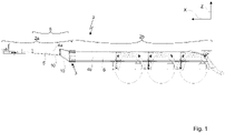
- FIG 1 shows a chassis 2 for a commercial vehicle from the side.
- the chassis 2 therefore preferably extends in the longitudinal direction X and the height direction Z.
- the carrier profiles of the first section 4a are preferably arranged in the front area 2a. These preferably have the transition region 8 which has a conical taper 10 .
- the support profiles 4a are preferably formed in such a way that they are higher in the height direction Z in at least one area than in another area.
- the support profiles are higher in the front area 2a at the point where the coupling point with the semi-trailer tractor 19 is. It is conceivable that the carrier profiles 4a at this coupling point 19 also have the lowest overall height in the vertical direction Z in order to obtain as much space as possible for cargo space above this area.
- the carrier profiles 4a in the first area 2a are preferably made from the first material 5 . All other components that are installed in the front area 2a are preferably also made of the first material 5 .
- the carrier profiles of the first section 4a in the front area 2a are connected at the connection point 3 to the carrier profiles of the second section 4b in the rear area 2b. It can be seen that the top edge of the support profiles in the second section 4b is arranged lower in the height direction Z than the top edge of the support profiles in the first section 4a. It can also be seen that the structural size of the support profiles in the second section 4b is formed larger than the support profiles in the first section 4a, at least in the height direction Z.
- the support profiles in the second section 4b are preferably made from the second material 6. It is conceivable that all other components that are attached to these carriers 4b consist of the second material 6.
- FIG. 2 shows a chassis 2 from the top view.
- the chassis 2 preferably extends in the longitudinal direction X and the width direction Y.
- connection point 3 at which the carrier profiles of the first section 4a are connected to the carrier profiles of the second section 4b, can also be seen here.
- the carrier profiles of the first section 4a not only have a conical shape in the height direction Z (not visible here), but that they preferably also converge in the width direction along the longitudinal direction X.
- the greatest distance between the carrier profiles 4a in the transverse direction Y is preferably at the connection point 3.
- the carrier profiles 4a preferably run conically towards one another from the connection point 3 in the longitudinal direction X to the coupling point with the tractor 19, so that they are the shortest at the coupling point 19 Have distance in the width direction Y from each other.
- At least one cross member is preferably arranged in the front area of the chassis 2a between the carrier profiles 4a.
- the crossbeam 9 is preferably located in the area in the longitudinal direction X just before the connection point 3.
- the support profiles 4a are preferably also connected to one another in the area of the coupling point 19.
- the carrier profiles 4a of the front area 2a are connected to the carrier profiles 4b of the second area 2b.
- the carrier profiles 4b preferably run parallel to one another in the second region 2b.
- the carrier profiles 4b are preferably connected to one another by at least two crossbeams 9.
- the crossmembers are located primarily in the area where the wheels are attached to the rear portion 2b of the chassis 2.
- the crossbeams between the support profiles in the first section 4a are preferably made of the first material 5 and the crossbeams 9 between the support profiles in the second section 4b are made of the second material 6.
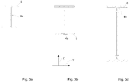
- FIG 2 four cutting lines A to D are drawn in the longitudinal direction X. These cutting lines refer to the Figures 3a to 3d , where the Figures 3a to 3d Represent cross sections of the carrier profiles and indicate the interfaces A to D at which point of the carrier profiles 4a and 4b the cross sections shown are located.
- Figures 3a to 3d represent cross sections of the carrier profiles 4a and 4b at different points along the longitudinal direction X.
- Figure 3a represents the smallest cross section of the carrier profile 4a, which is present in the front area 2a, in which the coupling point 19 is located.
- Figure 3b represents the cross section of the carrier profiles 4a in the transition area 8, the cross section increasing further in the longitudinal direction X towards the connection point 3.
- the carrier profiles in Figure 3a and 3b are therefore preferably made of the first material 5.
- the Figure 3d 12 shows the cross section of the carrier profiles 4b in the rear area 2b of the chassis 2, this cross section preferably remaining the same along the longitudinal direction X in the rear area 2b.
- the cross section shown preferably shows the carrier profiles, which consist of the second material 6 .
- Figures 3a, 3b and 3d therefore represent cross sections of either the carrier profiles from the front area 2a or from the rear area 2b.
- FIG. 3 shows a cross-section of the connection point 3, where at the connection point 3 the support profiles of the first and second sections 4a and 4b can be seen.
- connection point 3 is preferably constructed in such a way that the carrier profiles of the second section 4b have no recess, whereas the carrier profiles of the first section 4a are at least partially shaped in such a way that they can be pushed into one another with the carrier profiles of the second section 4b.
- the upper chord 11 and the lower chord 15 of the carrier profile of the first section 4a are preferably divided at the point at which the web plate 14 of the carrier profile of the second section 4b is arranged.
- the top chord 11 of the carrier profile of the first section 4a is preferably arranged below the top chord 12 of the carrier profile of the second section 4b in the vertical direction Z.
- the bottom chord 15 is from the carrier profile of the first section 4a in the vertical direction Z above the bottom flange 16 of the carrier profile of the second section 4b.
- the web plate of the carrier profile of the first section 13 is preferably arranged laterally in the width direction Y to the web plate of the carrier profile of the second section 14 .
- the top chords, bottom chords and web plates of the carrier profiles of the first and second sections 4a and 4b are preferably connected to one another with the connecting elements 7 .
- the connecting elements 7, which connect the upper and lower flanges to one another, are preferably passed through them along the height direction Z, while the connecting elements 7, which connect the web plates to one another, are preferably passed through them along the width direction Y.
- an additional reinforcement plate 17 is arranged next to the web plates of the carrier profiles of the first and second sections 13 and 14, which is also connected to the connecting elements 7 with the web plates 13 and 14 and thereby increases the stability of the connection point 3.
- figure 4 shows a chassis 2 from the side view, according to which the chassis extends in the longitudinal direction X and in the vertical direction Z.
- the chassis 2 in figure 4 Supporting elements 18 which, when parking the chassis 2 without a commercial vehicle 1, ensure that the chassis 2 does not tilt with the coupling point 19 in the direction of the roadway.
- the supports 18 can be attached either in the front area 2a, rear area 2b and/or at the connection point 3.
- the supports 18 preferably have a device so that they can be fastened to the connection point 3 with the connection elements 7 .
Landscapes
- Engineering & Computer Science (AREA)
- Chemical & Material Sciences (AREA)
- Combustion & Propulsion (AREA)
- Transportation (AREA)
- Mechanical Engineering (AREA)
- Architecture (AREA)
- Structural Engineering (AREA)
- Body Structure For Vehicles (AREA)
Priority Applications (1)
| Application Number | Priority Date | Filing Date | Title |
|---|---|---|---|
| EP21176283.6A EP4095019A1 (fr) | 2021-05-27 | 2021-05-27 | Châssis léger pour un véhicule utilitaire |
Applications Claiming Priority (1)
| Application Number | Priority Date | Filing Date | Title |
|---|---|---|---|
| EP21176283.6A EP4095019A1 (fr) | 2021-05-27 | 2021-05-27 | Châssis léger pour un véhicule utilitaire |
Publications (1)
| Publication Number | Publication Date |
|---|---|
| EP4095019A1 true EP4095019A1 (fr) | 2022-11-30 |
Family
ID=76159363
Family Applications (1)
| Application Number | Title | Priority Date | Filing Date |
|---|---|---|---|
| EP21176283.6A Withdrawn EP4095019A1 (fr) | 2021-05-27 | 2021-05-27 | Châssis léger pour un véhicule utilitaire |
Country Status (1)
| Country | Link |
|---|---|
| EP (1) | EP4095019A1 (fr) |
Citations (6)
| Publication number | Priority date | Publication date | Assignee | Title |
|---|---|---|---|---|
| JPH07291156A (ja) * | 1994-04-26 | 1995-11-07 | Tokyu Car Corp | コンテナトレーラのフレーム |
| DE102006027722B3 (de) * | 2006-06-16 | 2007-11-08 | Schmitz Cargobull Ag | Hauptlangträger-Segment |
| EP1997717A2 (fr) * | 2007-05-29 | 2008-12-03 | Schmitz Cargobull AG | Longeron avec section décalée et section de support d'essieu pour le châssis d'un semi-remorque |
| DE202011052016U1 (de) * | 2011-11-18 | 2013-03-20 | Kögel Trailer GmbH & Co. KG | Chassis |
| KR101978236B1 (ko) * | 2017-12-28 | 2019-09-03 | 주식회사 성우하이텍 | 프론트 사이드 멤버 |
| DE102018213487A1 (de) * | 2018-08-10 | 2020-02-13 | Bayerische Motoren Werke Aktiengesellschaft | Hybridbauteil sowie Verfahren zum Herstellen eines Hybridbauteils |
-
2021
- 2021-05-27 EP EP21176283.6A patent/EP4095019A1/fr not_active Withdrawn
Patent Citations (6)
| Publication number | Priority date | Publication date | Assignee | Title |
|---|---|---|---|---|
| JPH07291156A (ja) * | 1994-04-26 | 1995-11-07 | Tokyu Car Corp | コンテナトレーラのフレーム |
| DE102006027722B3 (de) * | 2006-06-16 | 2007-11-08 | Schmitz Cargobull Ag | Hauptlangträger-Segment |
| EP1997717A2 (fr) * | 2007-05-29 | 2008-12-03 | Schmitz Cargobull AG | Longeron avec section décalée et section de support d'essieu pour le châssis d'un semi-remorque |
| DE202011052016U1 (de) * | 2011-11-18 | 2013-03-20 | Kögel Trailer GmbH & Co. KG | Chassis |
| KR101978236B1 (ko) * | 2017-12-28 | 2019-09-03 | 주식회사 성우하이텍 | 프론트 사이드 멤버 |
| DE102018213487A1 (de) * | 2018-08-10 | 2020-02-13 | Bayerische Motoren Werke Aktiengesellschaft | Hybridbauteil sowie Verfahren zum Herstellen eines Hybridbauteils |
Similar Documents
| Publication | Publication Date | Title |
|---|---|---|
| DD297372A5 (de) | Kippfahrzeug | |
| WO2011107246A1 (fr) | Châssis de roulement pour véhicules utilitaires | |
| EP1927506B1 (fr) | Châssis de véhicule doté de traverses pour sécuriser le chargement et traverses | |
| DE102006027722B3 (de) | Hauptlangträger-Segment | |
| DE112016003933T5 (de) | Rahmen-Ladefläche-Vorrichtung | |
| EP1650060B1 (fr) | Dispositif d'attelage pour une ossature de carrosserie autoportante et ossature de carrosserie autoportante | |
| DE102004013348A1 (de) | Tankanordnung für Lastkraftwagen | |
| EP4095019A1 (fr) | Châssis léger pour un véhicule utilitaire | |
| EP2298597A1 (fr) | Véhicule, notamment remorque de véhicule | |
| WO2017178450A1 (fr) | Remorque de transport de véhicule autoportée | |
| EP1985494B1 (fr) | Faux-châssis de véhicule | |
| DE10140921B4 (de) | Fahrgestell für ein Nutzfahrzeug, Bausatz und Verfahren zur Spurverbreiterung und Radstandsverlängerung des Fahrgestells | |
| EP3348455B1 (fr) | Structure de support pour un véhicule utilitaire non entraîné | |
| DE102017103836B4 (de) | Aufliegerrahmen und Auflieger | |
| DE69720388T2 (de) | Sattelauflager von geringem Gewicht | |
| DE19522341C2 (de) | Fahrzeugrahmen für ein Transportfahrzeug | |
| DE102010016552B4 (de) | Längsträger zur Ladungssicherung | |
| DE4338299A1 (de) | Eisenbahngüterwagen zur Transportierung von Anhängern | |
| EP0566528A1 (fr) | Plate-forme pour véhicule utilitaire | |
| DE102021129186A1 (de) | Deichselrahmen für eine deichselanordnung eines fahrzeuganhängers sowie fahrzeuganhänger mit einem solchen deichselrahmen | |
| DE102021129218A1 (de) | Deichselanordnung für einen Fahrzeuganhänger sowie Fahrzeuganhänger mit einer solchen Deichselanordnung | |
| DE19843400A1 (de) | Bodengruppe für einen Fahrzeuganhänger, vorzugsweiseeinen Wohnanhänger | |
| DE102022112867A1 (de) | Fahrzeuganhänger | |
| DE102022112894A1 (de) | Fahrzeuganhänger | |
| DE102021129201A1 (de) | Deichselanordnung für ein Fahrgestell eines Fahrzeuganhängers sowie Anhänger für ein Zugfahrzeug mit einem Fahrgestell mit einer solchen Deichselanordnung |
Legal Events
| Date | Code | Title | Description |
|---|---|---|---|
| PUAI | Public reference made under article 153(3) epc to a published international application that has entered the european phase |
Free format text: ORIGINAL CODE: 0009012 |
|
| STAA | Information on the status of an ep patent application or granted ep patent |
Free format text: STATUS: THE APPLICATION HAS BEEN PUBLISHED |
|
| AK | Designated contracting states |
Kind code of ref document: A1 Designated state(s): AL AT BE BG CH CY CZ DE DK EE ES FI FR GB GR HR HU IE IS IT LI LT LU LV MC MK MT NL NO PL PT RO RS SE SI SK SM TR |
|
| STAA | Information on the status of an ep patent application or granted ep patent |
Free format text: STATUS: REQUEST FOR EXAMINATION WAS MADE |
|
| 17P | Request for examination filed |
Effective date: 20230324 |
|
| RBV | Designated contracting states (corrected) |
Designated state(s): AL AT BE BG CH CY CZ DE DK EE ES FI FR GB GR HR HU IE IS IT LI LT LU LV MC MK MT NL NO PL PT RO RS SE SI SK SM TR |
|
| STAA | Information on the status of an ep patent application or granted ep patent |
Free format text: STATUS: THE APPLICATION IS DEEMED TO BE WITHDRAWN |
|
| 18D | Application deemed to be withdrawn |
Effective date: 20231201 |