EP4095019A1 - Lightweight chassis for a commercial vehicle - Google Patents
Lightweight chassis for a commercial vehicle Download PDFInfo
- Publication number
- EP4095019A1 EP4095019A1 EP21176283.6A EP21176283A EP4095019A1 EP 4095019 A1 EP4095019 A1 EP 4095019A1 EP 21176283 A EP21176283 A EP 21176283A EP 4095019 A1 EP4095019 A1 EP 4095019A1
- Authority
- EP
- European Patent Office
- Prior art keywords
- section
- chassis
- profiles
- carrier
- area
- Prior art date
- Legal status (The legal status is an assumption and is not a legal conclusion. Google has not performed a legal analysis and makes no representation as to the accuracy of the status listed.)
- Withdrawn
Links
- 239000000463 material Substances 0.000 claims abstract description 55
- 230000007704 transition Effects 0.000 claims description 8
- 229910000851 Alloy steel Inorganic materials 0.000 claims description 4
- 229910000838 Al alloy Inorganic materials 0.000 claims description 3
- 230000008878 coupling Effects 0.000 description 11
- 238000010168 coupling process Methods 0.000 description 11
- 238000005859 coupling reaction Methods 0.000 description 11
- 239000000969 carrier Substances 0.000 description 5
- 229910045601 alloy Inorganic materials 0.000 description 4
- 239000000956 alloy Substances 0.000 description 4
- 230000002787 reinforcement Effects 0.000 description 3
- 238000010276 construction Methods 0.000 description 2
- 230000007797 corrosion Effects 0.000 description 2
- 238000005260 corrosion Methods 0.000 description 2
- 238000009434 installation Methods 0.000 description 2
- 239000011810 insulating material Substances 0.000 description 2
- 229910052751 metal Inorganic materials 0.000 description 2
- 239000002184 metal Substances 0.000 description 2
- FYYHWMGAXLPEAU-UHFFFAOYSA-N Magnesium Chemical compound [Mg] FYYHWMGAXLPEAU-UHFFFAOYSA-N 0.000 description 1
- 229910000831 Steel Inorganic materials 0.000 description 1
- 229910052782 aluminium Inorganic materials 0.000 description 1
- 239000004411 aluminium Substances 0.000 description 1
- XAGFODPZIPBFFR-UHFFFAOYSA-N aluminium Chemical compound [Al] XAGFODPZIPBFFR-UHFFFAOYSA-N 0.000 description 1
- 230000015572 biosynthetic process Effects 0.000 description 1
- 239000000919 ceramic Substances 0.000 description 1
- 239000011248 coating agent Substances 0.000 description 1
- 238000000576 coating method Methods 0.000 description 1
- 230000001419 dependent effect Effects 0.000 description 1
- 238000006056 electrooxidation reaction Methods 0.000 description 1
- 230000005484 gravity Effects 0.000 description 1
- 238000009413 insulation Methods 0.000 description 1
- 239000004922 lacquer Substances 0.000 description 1
- 239000007788 liquid Substances 0.000 description 1
- 229910052749 magnesium Inorganic materials 0.000 description 1
- 239000011777 magnesium Substances 0.000 description 1
- 229910052710 silicon Inorganic materials 0.000 description 1
- 239000010703 silicon Substances 0.000 description 1
- 239000010959 steel Substances 0.000 description 1
Images


Classifications
-
- B—PERFORMING OPERATIONS; TRANSPORTING
- B62—LAND VEHICLES FOR TRAVELLING OTHERWISE THAN ON RAILS
- B62D—MOTOR VEHICLES; TRAILERS
- B62D21/00—Understructures, i.e. chassis frame on which a vehicle body may be mounted
- B62D21/18—Understructures, i.e. chassis frame on which a vehicle body may be mounted characterised by the vehicle type and not provided for in groups B62D21/02 - B62D21/17
- B62D21/20—Understructures, i.e. chassis frame on which a vehicle body may be mounted characterised by the vehicle type and not provided for in groups B62D21/02 - B62D21/17 trailer type, i.e. a frame specifically constructed for use in a non-powered vehicle
-
- B—PERFORMING OPERATIONS; TRANSPORTING
- B62—LAND VEHICLES FOR TRAVELLING OTHERWISE THAN ON RAILS
- B62D—MOTOR VEHICLES; TRAILERS
- B62D27/00—Connections between superstructure or understructure sub-units
- B62D27/02—Connections between superstructure or understructure sub-units rigid
-
- B—PERFORMING OPERATIONS; TRANSPORTING
- B62—LAND VEHICLES FOR TRAVELLING OTHERWISE THAN ON RAILS
- B62D—MOTOR VEHICLES; TRAILERS
- B62D29/00—Superstructures, understructures, or sub-units thereof, characterised by the material thereof
- B62D29/008—Superstructures, understructures, or sub-units thereof, characterised by the material thereof predominantly of light alloys, e.g. extruded
-
- B—PERFORMING OPERATIONS; TRANSPORTING
- B62—LAND VEHICLES FOR TRAVELLING OTHERWISE THAN ON RAILS
- B62D—MOTOR VEHICLES; TRAILERS
- B62D53/00—Tractor-trailer combinations; Road trains
- B62D53/04—Tractor-trailer combinations; Road trains comprising a vehicle carrying an essential part of the other vehicle's load by having supporting means for the front or rear part of the other vehicle
- B62D53/06—Semi-trailers
- B62D53/061—Semi-trailers of flat bed or low loader type or fitted with swan necks
Landscapes
- Engineering & Computer Science (AREA)
- Chemical & Material Sciences (AREA)
- Combustion & Propulsion (AREA)
- Transportation (AREA)
- Mechanical Engineering (AREA)
- Architecture (AREA)
- Structural Engineering (AREA)
- Body Structure For Vehicles (AREA)
Abstract
Chassis für ein Nutzfahrzeug, insbesondere für seinen Sattelauflieger, wobei das Chassis mindestens zwei zumindest teilweise parallel zur Längsrichtung des Chassis verlaufende, Trägerprofile aufweist, welche in einer Breitenrichtung des Chassis voneinander beabstandet angeordnet sind, wobei das Chassis in der Längsrichtung einen ersten vorderen Bereich und einen zweiten hinteren Bereich aufweist.Erfindungsgemäß besteht jedes Trägerprofil in dem vorderen Bereich in einem ersten Abschnitt aus einem ersten Material mit einer ersten Dichte und in dem zweiten Bereich in einem zweiten Abschnitt aus einem zweiten Material mit einer zweiten, geringeren Dichte.Chassis for a commercial vehicle, in particular for its semi-trailer, the chassis having at least two support profiles which run at least partially parallel to the longitudinal direction of the chassis and are arranged at a distance from one another in a width direction of the chassis, the chassis having a first front region and a second rear area.According to the invention, each carrier profile consists in the front area in a first section of a first material with a first density and in the second area in a second section of a second material with a second, lower density.
Description
Die Erfindung betrifft ein Chassis für ein Nutzfahrzeug, insbesondere für seinen Sattelauflieger, wobei das Chassis mindestens zwei zumindest teilweise parallel zur Längsrichtung des Chassis verlaufende, Trägerprofile aufweist, welche in einer Breitenrichtung des Chassis voneinander beabstandet angeordnet sind, wobei das Chassis in der Längsrichtung einen ersten vorderen Bereich und einen zweiten hinteren Bereich aufweist.The invention relates to a chassis for a commercial vehicle, in particular for its semi-trailer, the chassis having at least two support profiles which run at least partially parallel to the longitudinal direction of the chassis and are arranged at a distance from one another in the width direction of the chassis, the chassis having a first front region and a second rear region.
Chassis dieser Art werden vor allem als Sattelauflieger verwendet, welche in Verbund mit einer Sattelzugmaschine als Sattelzug bekannt sind. Aus dem Stand der Technik sind dabei diverse Modelle bekannt, welche für den Transport verschiedener Güter angepasst sind. Vor allem sind Sattelauflieger bekannt, welche Aufnahmen für ISO-Container, speziell angepasste Behälter und Ladeflächen für Stückgut, Schüttgut und Flüssigkeitstransporte aufweisen. Während auf privaten Geländen beliebige Fahrzeuge eingesetzt werden können, so gelten für Sattelzüge, welche im öffentlichen Straßenverkehr teilnehmen, in vielen Ländern Einschränkungen durch Normen und Vorschriften die eingehalten werden müssen. Entsprechende Normen und Vorschriften beschränken zumeist vor allem die maximale Größe und das maximale Gewicht von Sattelzügen, weshalb es von besonderem Interesse ist einen Sattelzug und damit die Zugmaschine und den Sattelauflieger so kompakt und leicht wie möglich zu gestalten.Chassis of this type are mainly used as semi-trailers, which are known as semi-trailers in connection with a semi-trailer tractor. Various models are known from the prior art, which are adapted for the transport of different goods. Above all, semi-trailers are known which have receptacles for ISO containers, specially adapted containers and loading areas for general cargo, bulk goods and liquid transport. While any vehicle can be used on private property, in many countries there are restrictions due to standards and regulations that must be observed for articulated lorries that take part in public road traffic. Appropriate standards and regulations mostly restrict above all the maximum size and the maximum weight of articulated lorries, which is why it is of particular interest to design an articulated lorry and thus the tractor unit and the semi-trailer as compact and light as possible.
Die Beschränkungen für Sattelzüge betreffen vor allem die maximalen Ausmaße des Sattelzuges in der Höhe, Breite und Länge, sowie das maximal zulässige Gesamtgewicht. Da nicht nur die Größe und das Gewicht beschränkt sind, sondern auch etwaige Vorschriften bezüglich der Stabilität von Sattelaufliegern und Zugmaschinen eingehalten werden müssen, können Hersteller nicht pauschal auf Leichtbau setzten und die Stabilität vernachlässigen. Da vor allem beim Transport von Schüttgut jedoch besonders die Begrenzung des maximalen Gesamtgewichts des Sattelzugs eine Rolle spielt, wäre es vorteilhaft das Eigengewicht des Sattelzugs zu verringern um mehr Schüttgut in einer Ladung transportieren zu können.The restrictions for articulated lorries primarily concern the maximum dimensions of the articulated lorry in terms of height, width and length, as well as the maximum permissible total weight. Since not only the size and weight are limited, but also any regulations regarding When it comes to the stability of semi-trailers and tractor units, manufacturers cannot simply rely on lightweight construction and neglect stability. However, since the limitation of the maximum total weight of the articulated lorry plays a role, especially when transporting bulk goods, it would be advantageous to reduce the dead weight of the articulated lorry in order to be able to transport more bulk goods in one load.
Es ist daher die Aufgabe der vorliegenden Erfindung ein Leichtbau-Chassis bereitzustellen, welches die Anforderungen der Stabilität für die Verwendung auf öffentlichen Straßen erfüllt und im Vergleich zu herkömmlichen Chassis keine Einschränkungen im Frachtraum aufweist.It is therefore the object of the present invention to provide a lightweight chassis that meets the stability requirements for use on public roads and, in comparison to conventional chassis, does not have any limitations in terms of cargo space.
Diese Aufgabe wird gelöst durch ein Chassis für ein Nutzfahrzeug gemäß dem Anspruch 1. Die abhängigen Ansprüche beziehen sich auf vorteilhafte Ausführungsformen.This object is solved by a chassis for a commercial vehicle according to
Erfindungsgemäß besteht jedes Trägerprofil in dem vorderen Bereich in einem ersten Abschnitt aus einem ersten Material mit einer ersten Dichte und in dem zweiten Bereich in einem zweiten Abschnitt aus einem zweiten Material mit einer zweiten, geringeren Dichte.According to the invention, each carrier profile consists in the front area in a first section of a first material with a first density and in the second area in a second section of a second material with a second, lower density.
Da der vordere Bereich des Chassis bei Fahrt zumindest teilweise auf der Zugmaschine aufliegt und der Bereich, welcher in der Höhenrichtung über dieser Koppelstelle von Zugfahrzeug und Sattelauflieger liegt, vorzugsweise als Stauraum für Transportgut verwendet wird, sind die Trägerprofile im ersten Abschnitt vorzugsweise so kompakt wie möglich ausgelegt. Vorzugsweise sind die Trägerprofile im vorderen Bereich vor allem in ihrer Größe in der Höhenrichtung so klein wie möglich ausgelegt um möglichst viel Stauraum über der Koppelstelle zu erlangen.Since the front area of the chassis rests at least partially on the towing vehicle when driving and the area which is in the height direction above this coupling point of towing vehicle and semi-trailer is preferably used as storage space for goods to be transported, the carrier profiles in the first section are preferably as compact as possible designed. The carrier profiles in the front area are preferably designed to be as small as possible, especially in terms of their size in the height direction, in order to obtain as much storage space as possible above the coupling point.
Im hinteren Bereich des Fahrzeugs spielt die Größe der Trägerprofile vorzugsweise keine Rolle, da dort der Bauraum unterhalb des Chassis nicht durch das Zugfahrzeug oder eine Koppelstelle begrenzt ist. Es ist denkbar, dass deshalb die Trägerprofile im hinteren Bereich des Chassis zumindest teilweise ein Leichtmetall aufweisen. Da der Bauraum im hinteren Bereich vorzugsweise nicht eingeschränkt ist, können die Träger mit dem Leichtmetall größer ausgeformt sein, als die Träger im vorderen Bereich. Vor allem können die Träger größer in der Höhenrichtung ausgeformt sein.In the rear area of the vehicle, the size of the carrier profiles is preferably irrelevant, since the installation space below the chassis is not limited there by the towing vehicle or a coupling point. It is conceivable that the carrier profiles in the rear area of the chassis therefore have at least part of a light metal. Since the installation space in the rear area is preferably not restricted, the carrier with the light metal can be formed larger than the carrier in the front area. Above all, the beams can be formed larger in the height direction.
Vorzugsweise ist das Material im vorderen Bereich stabiler als das Material im hinteren Bereich, wodurch die Trägerprofile im vorderen Bereich kleiner ausgelegt werden können, um Platz, vor allem in der Höhenrichtung, einzusparen.The material in the front area is preferably more stable than the material in the rear area, as a result of which the support profiles in the front area can be designed to be smaller in order to save space, especially in the vertical direction.
Die Trägerprofile im vorderen Bereich und die Trägerprofile im hinteren Bereich sind vorzugsweise jeweils zwei physikalisch voneinander getrennte Träger. Vorzugsweise besteht das Chassis demnach aus vier einzelnen Trägern, welche miteinander verbunden werden.The carrier profiles in the front area and the carrier profiles in the rear area are preferably two carriers that are physically separate from one another. The chassis therefore preferably consists of four individual carriers which are connected to one another.
Gemäß zumindest einer weiteren Ausführungsform ist das erste Material vorzugsweise eine Stahllegierung, wobei das zweite Material vorzugsweise eine Aluminiumlegierung ist.According to at least one further embodiment, the first material is preferably a steel alloy, with the second material preferably being an aluminum alloy.
Es ist denkbar, dass die Stahllegierung eine solche ist, wie sie für den Bau von herkömmlichen Chassis für Nutzfahrzeuge verwendet wird. Es ist auch denkbar, dass die Stahllegierung eine hochfeste Legierung ist um die Stabilität bei kleinen Profilquerschnitten der Träger zu erhöhen.It is conceivable that the steel alloy is one used in the construction of conventional chassis for commercial vehicles. It is also conceivable that the steel alloy is a high-strength alloy in order to increase the stability in the case of small profile cross-sections of the carrier.
Vorzugsweise ist die Aluminiumlegierung eine Legierung mit Magnesium und/oder Silicium. Bevorzugt werden dabei die Legierungen AlMgSi 0,7 oder AlMgSi 1 für den hinteren Abschnitt der Trägerprofile verwendet.The aluminum alloy is preferably an alloy with magnesium and/or silicon. The alloys AlMgSi 0.7 or AlMgSi 1 are preferably used for the rear section of the support profiles.
Gemäß zumindest einer weiteren Ausführungsform weist das Chassis weiterhin mindestens einen Querträger auf, welcher mit seiner Längsrichtung zumindest teilweise in der Breitenrichtung zwischen den Trägerprofilen angeordnet ist und diese miteinander verbindet, wobei die Querträger vorzugsweise aus dem ersten und/oder zweiten Material bestehen.According to at least one further embodiment, the chassis also has at least one crossbeam, which is arranged with its longitudinal direction at least partially in the width direction between the support profiles and connects them to one another, the crossbeams preferably consisting of the first and/or second material.
Gemäß zumindest einer weiteren Ausführungsform bestehen die Querträger zwischen den Trägerprofilen im ersten Abschnitt aus dem ersten Material, wobei die Querträger zwischen den Trägerprofilen im zweiten Abschnitt aus dem zweiten Material bestehen.According to at least one further embodiment, the crossbeams between the support profiles in the first section consist of the first material, with the crossbeams between the support profiles in the second section being made of the second material.
Es ist denkbar, dass die Querträger neben dem ersten und zweiten Material auch aus anderen Materialien bestehen können. Weiterhin ist es denkbar, dass alle Querträger das gleiche Material aufweisen.It is conceivable that the cross members can also consist of other materials in addition to the first and second material. Furthermore, it is conceivable that all cross members have the same material.
Vorzugsweise bestehen Querträger jeweils aus dem gleichen Material, wie die Trägerprofile, die sie miteinander verbinden. Vorzugsweise bestehen Querträger im vorderen Abschnitt demnach aus dem ersten Material, wohingegen Querträger im hinteren Abschnitt vorzugsweise aus dem zweiten Material bestehen.Cross beams are preferably made of the same material as the beam profiles that connect them to one another. Preferably there are cross members in the front section accordingly made of the first material, whereas cross members in the rear section are preferably made of the second material.
Bevorzugt sind die Trägerprofile im vorderen Abschnitt mit einem Querträger verbunden. Vorzugsweise sind die Trägerprofile im hinteren Abschnitt mit mindestens zwei Querträgern verbunden.The carrier profiles are preferably connected to a cross member in the front section. The carrier profiles are preferably connected to at least two cross members in the rear section.
Vorzugsweise sind, insbesondere wenn die Querträger aus dem gleichen Material bestehen wie die Trägerprofile die sie verbinden, die Querträger mit den Trägerprofilen verschweißt.The crossbeams are preferably welded to the beam profiles, particularly if the crossbeams are made of the same material as the beam profiles that connect them.
Es ist jedoch denkbar, dass die Trägerprofile mit den Querträgern verschraubt, vernietet oder ähnlich miteinander verbunden sind.However, it is conceivable that the carrier profiles are screwed, riveted or similarly connected to the cross members.
Vorzugsweise sind die Querträger orthogonal zu den Trägerprofilen angeordnet. Eine Anordnung über Kreuz ist jedoch auch denkbar.The crossbeams are preferably arranged orthogonally to the beam profiles. However, a cross arrangement is also conceivable.
Gemäß zumindest einer weiteren Ausführungsform sind die Trägerprofile aus dem ersten Abschnitt mit den Trägerprofilen aus dem zweiten Abschnitt an einer Verbindungsstelle über mindestens ein Verbindungselement formfest miteinander verbunden.According to at least one further embodiment, the carrier profiles from the first section are connected to the carrier profiles from the second section in a form-fixed manner at a connection point via at least one connection element.
Es ist denkbar, dass es somit einen vorderen und einen hinteren Abschnitt des Chassis gibt, wobei diese Abschnitte vorzugsweise unabhängig voneinander gebaut werden und anschließend über die Verbindungsstelle miteinander verbunden werden.It is conceivable that there is thus a front and a rear section of the chassis, these sections preferably being built independently of one another and then connected to one another via the joint.
Insbesondere ist es denkbar, dass dadurch beliebige vordere Abschnitte mit beliebigen hinteren Abschnitten verbindbar sind und demnach die einzelnen Abschnitte austauschbar sind. Es ist denkbar, dass dies besonders bei Unfällen oder Beschädigungen eines Abschnitts vorteilhaft ist, da nicht das ganze Chassis ersetzt werden muss.In particular, it is conceivable that as a result any front sections can be connected to any rear sections and the individual sections can therefore be exchanged. It is conceivable that this is particularly advantageous in the event of an accident or damage to one section, since the entire chassis does not have to be replaced.
Bevorzugt haben die unterschiedlichen Materialien an der Verbindungsstelle keinen elektrischen Kontakt miteinander, um die Bildung eines galvanischen Elementes zu vermeiden und dadurch Korrosion an der Verbindungsstelle vorzubeugen.The different materials at the connection point preferably have no electrical contact with one another in order to avoid the formation of a galvanic element and thereby prevent corrosion at the connection point.
Bevorzugt werden ein vorderer Abschnitt und ein hinterer Abschnitt an der Verbindungsstelle über Verbindungselemente miteinander verbunden. Es ist denkbar, dass diese Verbindungselemente Schrauben, Nieten, Bolzen und/oder ähnliche Mittel zur Befestigung sein können.A front section and a rear section are preferably connected to one another at the connection point via connection elements. It is conceivable that these connecting elements can be screws, rivets, bolts and/or similar fastening means.
Vorzugsweise bestehen die Befestigungselemente aus Stahl, um eine hohe Stabilität zu gewährleisten. Es ist denkbar, dass die Befestigungselemente auch aus Aluminium, Keramik, einer Legierung und/oder aus anderen Materialien bestehen.Preferably, the fasteners are made of steel to ensure high stability. It is conceivable that the fastening elements also consist of aluminium, ceramics, an alloy and/or other materials.
Sofern die Verbindungselemente an einem Träger befestigt werden, welcher aus einem anderen Material besteht, weisen die Verbindungselemente vorzugsweise keinen elektrischen Kontakt zu dem Träger auf. Vorzugsweise sind alle Bauteile, zumindest aber alle unterschiedlichen Materialien, an der Verbindungsstelle elektrisch voneinander isoliert.If the connecting elements are attached to a carrier made of a different material, the connecting elements preferably have no electrical contact with the carrier. All components, but at least all different materials, are preferably electrically insulated from one another at the connection point.
Vorzugsweise ist das gesamte Chassis so aufgebaut, dass sämtliche unterschiedlichen Materialien voneinander isoliert sind.Preferably, the entire chassis is constructed in such a way that all the different materials are isolated from one another.
Gemäß zumindest einer weiteren Ausführungsform sind die Trägerprofile an der Verbindungsstelle endseitig und zumindest teilweise überlappend miteinander verschraubt.According to at least one further embodiment, the carrier profiles are screwed to one another at the connection point at the end and at least partially overlapping.
Vorzugsweise sind die Trägerprofile des vorderen und hinteren Abschnitts so geformt, dass sie zumindest teilweise ineinander schiebbar sind. Vorzugsweise wird neben der einfachen Schraubverbindung der Träger zumindest an den Stegblechen ein zusätzliches Verstärkungsblech verschraubt um eine Zweischneidigkeit der Schrauben an der Verbindungsstelle zu gewährleisten und damit die Stabilität der Verbindungsstelle zu erhöhen.The carrier profiles of the front and rear sections are preferably shaped in such a way that they can be pushed into one another at least partially. In addition to the simple screw connection of the carrier, an additional reinforcement plate is preferably screwed at least to the web plates in order to ensure that the screws are double-edged at the connection point and thus increase the stability of the connection point.
Gemäß zumindest einer weiteren Ausführungsform sind das erste Material und das zweite Material an der Verbindungsstelle voneinander elektrisch isoliert sind. Vorzugsweise wird dadurch elektrochemische Korrosion an den Bauteilen vorgebeugt.In accordance with at least one further embodiment, the first material and the second material are electrically insulated from one another at the connection point. This preferably prevents electrochemical corrosion on the components.
Vorzugsweise wird für eine entsprechende Isolierung der Materialien zumindest ein isolierendes Material verwendet. Es ist denkbar, dass ein entsprechendes isolierendes Material, eine Beschichtung, Lack, eine zwischengelegte Matte und/oder ähnliches sein können.At least one insulating material is preferably used for appropriate insulation of the materials. It is conceivable that a corresponding insulating material can be a coating, lacquer, an interposed mat and/or the like.
Vorzugsweise sind zumindest Teile der Oberflächen vom Chassis mit einem zusätzlichen Korrosionsschutz versehen.At least parts of the surfaces of the chassis are preferably provided with an additional protection against corrosion.
Gemäß zumindest einer weiteren Ausführungsform ist der Profilquerschnitt der Trägerprofile im ersten Abschnitt kleiner, als der Profilquerschnitt der Trägerprofile im zweiten Abschnitt.According to at least one further embodiment, the profile cross section of the carrier profiles in the first section is smaller than the profile cross section of the carrier profiles in the second section.
Es ist denkbar, dass das die Trägerprofile im vorderen Abschnitt kleiner sind als die Trägerprofile im hintern Abschnitt, da die maximale Bauhöhe in der Höhenrichtung im vorderen Abschnitt begrenzt ist.It is conceivable that the carrier profiles in the front section are smaller than the carrier profiles in the rear section, since the maximum structural height in the vertical direction is limited in the front section.
Vorzugsweise ist die Baugröße der Trägerprofile im hinteren Abschnitt nicht begrenzt, weshalb die Profile dort größer sind, zumindest in der Höhenrichtung, und vorzugsweise auch aus einem leichteren Material bestehen, um das Gewicht des Chassis zu minimieren.Preferably, the structural size of the support profiles in the rear section is not limited, which is why the profiles are larger there, at least in the height direction, and preferably also made of a lighter material in order to minimize the weight of the chassis.
Es ist denkbar, dass durch die unterschiedlichen Materialeigenschaften und Baugrößen der Träger im vorderen und hinteren Abschnitt, die Träger der beiden Abschnitte dennoch ähnliche Stabilitäten aufweisen.It is conceivable that due to the different material properties and sizes of the carriers in the front and rear sections, the carriers of the two sections nevertheless have similar stability.
Gemäß zumindest einer weiteren Ausführungsform weisen die Trägerprofile im ersten Abschnitt an dem Ende, mit dem sie mit den Trägerprofilen im zweiten Abschnitt verbunden sind, einen Übergangsbereich des Profilquerschnitts auf, sodass sie an der Verbindungsstelle den gleichen Profilquerschnitt aufweisen wie die Trägerprofile im zweiten Abschnitt.According to at least one further embodiment, the carrier profiles in the first section have a transition area of the profile cross section at the end with which they are connected to the carrier profiles in the second section, so that they have the same profile cross section at the connection point as the carrier profiles in the second section.
Vorzugsweise weisen die Trägerprofile mit dem dichteren Material die konische Ausformung auf, damit in dem Abschnitt mit dem leichteren Material (und damit gleichzeitig instabileren Material) keine Schwachstelle entsteht.The carrier profiles with the denser material preferably have the conical shape so that no weak point occurs in the section with the lighter material (and thus at the same time more unstable material).
Gemäß zumindest einer weiteren Ausführungsform weisen die Trägerprofile im ersten Abschnitt im Übergangsbereich zumindest teilweise eine konische Verjüngung auf.According to at least one further embodiment, the support profiles in the first section in the transition area have at least a partial conical taper.
Vorzugsweise weisen die Trägerprofile im ersten Abschnitt zusätzlich eine Versetzung der Trägerhöhe in der Höhenrichtung auf, sodass die Trägerprofile im ersten Abschnitt weiter in der Höhenrichtung des Chassis hervorragen, als die Trägerprofile im zweiten Abschnitt. Vorzugsweise wird dadurch der Masseschwerpunkt des Sattelaufliegers in Richtung der Fahrbahn verlagert.Preferably, the carrier profiles in the first section additionally have an offset of the carrier height in the height direction, so that the carrier profiles in the first section protrude further in the height direction of the chassis than the carrier profiles in the second section. The center of gravity of the semi-trailer is thereby preferably shifted in the direction of the roadway.
Es ist denkbar, dass ein entsprechender Versatz der Trägerhöhe in dem Übergangsbereich mit der konischen Verjüngung angeordnet ist.
Gemäß zumindest einer weiteren Ausführungsform weisen, entgegen einer vorwärts Fahrtrichtung betrachtet, die Trägerprofile im ersten Abschnitt vor der Verbindungsstelle das erste Material auf, wobei hinter der Verbindungsstelle die Trägerprofile des zweiten Abschnitts mit dem zweiten Material angeordnet sind.It is conceivable that a corresponding offset of the carrier height is arranged in the transition area with the conical taper.
According to at least one further embodiment, viewed against a forward direction of travel, the carrier profiles in the first section have the first material in front of the connection point, with the carrier profiles of the second section having the second material being arranged behind the connection point.
Es ist denkbar, dass an dem Chassis weiterhin mindestens ein Standfuß angebracht ist, welcher beim Abstellen des Sattelaufliegers ohne Zugmaschine ein Kippen des vorderen Abschnitts des Chassis in Richtung Fahrbahn vermeidet.It is conceivable that at least one stand is also attached to the chassis, which prevents the front section of the chassis from tipping in the direction of the roadway when the semi-trailer is parked without a tractor unit.
Vorzugsweise sind an zumindest zwei der Trägerprofile Stützen angebracht.Supports are preferably attached to at least two of the carrier profiles.
Vorzugsweise sind die Stützen an den Trägerprofilen des vorderen und/oder hinteren Abschnitts angebracht. Es ist denkbar, dass die Stützen auch an der Verbindungsstelle angebracht sind und vorzugsweise mit den Verbindungselementen befestigt sind.Preferably, the supports are attached to the carrier profiles of the front and/or rear section. It is conceivable that the supports are also attached to the connection point and are preferably fastened with the connection elements.
Vorzugsweise bestehen auch die Stützen zumindest teilweise aus einem der Materialien.Preferably, the supports also consist at least partially of one of the materials.
Weitere Ziele, Vorteile, Merkmale und Anwendungsmöglichkeiten der vorliegenden Erfindung ergeben sich aus der nachfolgenden Beschreibung von Ausführungsbeispielen anhand der Zeichnungen. Dabei bilden alle beschriebenen und/oder bildlich dargestellten Merkmale für sich oder in beliebiger sinnvoller Kombination den Gegenstand der vorliegenden Erfindung, auch unabhängig von ihrer Zusammenfassung in den Ansprüchen oder deren Rückbeziehung.Further goals, advantages, features and possible applications of the present invention result from the following description of exemplary embodiments with reference to the drawings. All the features described and/or illustrated form the subject matter of the present invention, either alone or in any meaningful combination, even independently of their summary in the claims or their back-reference.
Es zeigen:
- Fig. 1
- ein Chassis aus der Seitenansicht
- Fig. 2
- ein Chassis aus der Draufsicht
- Fig. 3a-d
- eine Schnittansicht von Trägerprofilen
- Fig. 4
- ein Chassis mit Stützen aus der Seitenansicht
- 1
- a chassis from the side
- 2
- a chassis from the top view
- Fig. 3a-d
- a sectional view of carrier profiles
- 4
- a chassis with supports from the side view
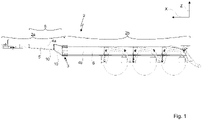
Die Trägerprofile 4a im ersten Bereich 2a sind vorzugsweise aus dem ersten Material 5 gefertigt. Vorzugsweise sind auch alle weiteren Bauteile, welche in dem vorderen Bereich 2a verbaut sind aus dem ersten Material 5 gefertigt.The carrier profiles 4a in the
Die Trägerprofile des ersten Abschnitts 4a im vorderen Bereich 2a sind an der Verbindungsstelle 3 mit den Trägerprofilen des zweiten Abschnitts 4b im hinteren Bereich 2b verbunden. Es ist zu sehen, dass die Oberkante der Trägerprofile im zweiten Abschnitt 4b in der Höhenrichtung Z niedriger angeordnet ist, als die Oberkante der Trägerprofile im ersten Abschnitt 4a. Weiterhin ist zu sehen, dass die Trägerprofile im zweiten Abschnitt 4b in ihrer Baugröße zumindest in der Höhenrichtung Z größer ausgeformt sind, als die Trägerprofile im ersten Abschnitt 4a.The carrier profiles of the
Die Trägerprofile im zweiten Abschnitt 4b sind vorzugsweise aus dem zweiten Material 6 gefertigt. Es ist denkbar, dass auch alle weiteren Bauteile, welche an diesen Trägern 4b befestigt werden, aus dem zweiten Material 6 bestehen.The support profiles in the
In dem hinteren Bereich des Chassis 2a sind weiterhin die Reifen des Chassis, sowie ein Unterfahrschutz zu erkennen.In the rear area of the
Aus der Draufsicht sind wiederum der vordere Bereich 2a und der hintere Bereich 2b des Chassis zu erkennen. Die Verbindungsstelle 3, an welcher die Trägerprofile des ersten Abschnitts 4a mit den Trägerprofilen des zweiten Abschnitts 4b verbunden sind, ist dabei ebenfalls zu erkennen.From the top view, the
In dem vorderen Bereich 2a ist zu erkennen, dass die Trägerprofile des ersten Abschnitts 4a nicht nur in der Höhenrichtung Z eine konische Ausformung aufweisen (hier nicht erkennbar), sondern diese vorzugsweise auch in der Breitenrichtung entlang der Längsrichtung X zusammenlaufen. Dabei ist die größte Distanz zwischen den Trägerprofilen 4a in der Querrichtung Y vorzugsweise an der Verbindungsstelle 3. Vorzugsweise verlaufen die Trägerprofile 4a von der Verbindungsstelle 3 in Längsrichtung X zur Koppelstelle mit der Zugmaschine 19, konisch aufeinander zu, sodass sie an der Koppelstelle 19 den geringsten Abstand in der Breitenrichtung Y zueinander haben.In the
Vorzugsweise ist zumindest ein Querträger im vorderen Bereich des Chassis 2a zischen den Trägerprofilen 4a angeordnet. Vorzugsweise liegt der Querträger 9 im Bereich in Längsrichtung X kurz vor der Verbindungsstelle 3. Die Trägerprofile 4a sind vorzugsweise ebenfalls im Bereich der Koppelstelle 19 miteinander verbunden.At least one cross member is preferably arranged in the front area of the
An der Verbindungsstelle 3 sind die Trägerprofile 4a des vorderen Bereichs 2a mit den Trägerprofilen 4b des zweiten Bereichs 2b verbunden. Vorzugsweise verlaufen die Trägerprofile 4b im zweiten Bereich 2b parallel zueinander.At the
Die Trägerprofile 4b sind vorzugsweise durch mindestens zwei Querträger 9 miteinander verbunden. Vorzugsweise befinden sich die Querträger vor allem in dem Bereich, in welchem die Räder an dem hinteren Bereich 2b des Chassis 2 befestigt sind.The carrier profiles 4b are preferably connected to one another by at least two
Bevorzugt bestehen die Querträger zwischen den Trägerprofilen im ersten Abschnitt 4a aus dem ersten Material 5 und die Querträger 9 zwischen den Trägerprofilen im zweiten Abschnitt 4b aus dem zweiten Material 6.The crossbeams between the support profiles in the
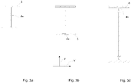
In
Die
Die Trägerprofile in
Die
Die
Die Verbindungsstelle 3 ist vorzugsweise so aufgebaut, dass die Trägerprofile des zweiten Abschnitts 4b keine Aussparung aufweisen, wohingegen die Trägerprofile des ersten Abschnitts 4a zumindest teilweise so geformt sind, dass sie mit den Trägerprofilen des zweiten Abschnitts 4b ineinander schiebbar sind.The
Vorzugsweise sind der Obergurt 11 und der Untergurt 15 des Trägerprofils des ersten Abschnitts 4a an der Stelle unterteilt, an welcher das Stegblech 14 vom Trägerprofil des zweiten Abschnitts 4b angeordnet ist. Vorzugsweise ist der Obergurt 11 vom Trägerprofil des ersten Abschnitts 4a in der Höhenrichtung Z unterhalb des Obergurtes 12 vom Trägerprofil des zweiten Abschnitts 4b angeordnet. Vorzugsweise ist der Untergurt 15 vom Trägerprofil des ersten Abschnitts 4a in der Höhenrichtung Z oberhalb des Untergurtes 16 vom Trägerprofil des zweiten Abschnitts 4b angeordnet.The
Vorzugsweise ist das Stegblech vom Trägerprofil des ersten Abschnitts 13 in der Breitenrichtung Y seitlich zum Stegblech vom Trägerprofil des zweiten Abschnitts 14 angeordnet.The web plate of the carrier profile of the
Die Obergurte, Untergurte und Stegbleche der Trägerprofile des ersten und zweiten Abschnitts 4a und 4b sind vorzugsweise mit den Verbindungselementen 7 miteinander verbunden. Dabei sind die Verbindungselemente 7, welche die Ober- und Untergurte miteinander verbinden, vorzugsweise entlang der Höhenrichtung Z durch diese geführt, während die Verbindungselemente 7, welche die Stegbleche miteinander verbinden, vorzugsweise entlang der Breitenrichtung Y durch diese hindurchgeführt sind.The top chords, bottom chords and web plates of the carrier profiles of the first and
Vorzugsweise ist, neben den Stegblechen der Trägerprofile des ersten und zweiten Abschnitts 13 und 14, ein zusätzliches Verstärkungsblech 17 angeordnet, welches ebenfalls mit den Verbindungselementen 7 mit den Stegblechen 13 und 14 verbunden wird und dadurch die Stabilität der Verbindungsstelle 3 erhöht.Preferably, an
Es ist denkbar, dass die Stützen 18 entweder im vorderen Bereich 2a, hinteren Bereich 2b und/oder an der Verbindungsstelle 3 angebracht werden können. Vorzugsweise weisen die Stützen 18 eine Vorrichtung auf, sodass sie mit den Verbindungselementen 7 an der Verbindungsstelle 3 befestigbar sind.It is conceivable that the
- 11
- Nutzfahrzeugcommercial vehicle
- 22
- Chassischassis
- 2a2a
- erster, vorderer Bereich des Chassisfirst, front area of the chassis
- 2b2 B
- zweiter, hinterer Bereich des Chassissecond, rear area of the chassis
- 33
- Verbindungsstelleconnection point
- 44
- Trägerprofilecarrier profiles
- 4a4a
- Trägerprofil des ersten, vorderen AbschnittsBeam profile of the first front section
- 4b4b
- Trägerprofil des zweiten, hinteren AbschnittsBeam profile of the second, rear section
- 55
- erstes Materialfirst material
- 66
- zweites Materialsecond material
- 77
- Verbindungselementfastener
- 88th
- Übergangsbereich ProfilquerschnittTransition area profile cross section
- 99
- Querträgercross member
- 1010
- konische Ausformungconical shape
- 1111
- Obergurt vom Trägerprofil des ersten AbschnittsTop chord of the beam profile of the first section
- 1212
- Obergurt vom Trägerprofil des zweiten AbschnittsTop chord from the beam profile of the second section
- 1313
- Stegblech vom Trägerprofil des ersten AbschnittsWeb plate from the beam profile of the first section
- 1414
- Stegblech vom Trägerprofil des zweiten AbschnittsWeb plate from the carrier profile of the second section
- 1515
- Untergurt vom Trägerprofil des ersten AbschnittsLower chord from the beam profile of the first section
- 1616
- Untergurt vom Trägerprofil des zweiten AbschnittsLower chord of the beam profile of the second section
- 1717
- Verstärkungsblech für Zweischneidigkeit der SchraubverbindungReinforcement plate for double-edged screw connection
- 1818
- Stützelement für ChassisSupport element for chassis
- 1919
- Koppelstelle zwischen Sattelauflieger und ZugmaschineCoupling point between semi-trailer and tractor
- XX
- Längsrichtung des NutzfahrzeugsLongitudinal direction of the commercial vehicle
- YY
- Breitenrichtunglatitude direction
- ZZ
- Höhenrichtungheight direction
Claims (11)
dadurch gekennzeichnet, dass
jedes Trägerprofil (4) in dem vorderen Bereich (2a) in einem ersten Abschnitt (4a) aus einem ersten Material (5) mit einer ersten Dichte und in dem zweiten Bereich (2b) in einem zweiten Abschnitt (4b) aus einem zweiten Material (6) mit einer zweiten, geringeren Dichte besteht.Chassis (2) for a commercial vehicle (1), in particular for its semi-trailer, the chassis (2) having at least two carrier profiles (4) running at least partially parallel to the longitudinal direction (X) of the chassis (2) and which are in a width direction ( Y) of the chassis (2) are arranged spaced apart from one another, the chassis (2) having a first front area (2a) and a second rear area (2b) in the longitudinal direction (X),
characterized in that
each carrier profile (4) in the front area (2a) in a first section (4a) made of a first material (5) with a first density and in the second area (2b) in a second section (4b) made of a second material ( 6) with a second, lower density.
dadurch gekennzeichnet, dass
das erste Material (5) vorzugsweise eine Stahllegierung ist, wobei das zweite Material (6) vorzugsweise eine Aluminiumlegierung ist.Chassis (2) according to claim 1,
characterized in that
the first material (5) is preferably a steel alloy, the second material (6) preferably being an aluminum alloy.
dadurch gekennzeichnet, dass
das Chassis (2) weiterhin mindestens einen Querträger (9) aufweist, welcher zumindest teilweise in der Breitenrichtung (Y) zwischen den Trägerprofilen (4) angeordnet ist und diese miteinander verbindet, wobei die Querträger (9) aus dem ersten und/oder zweiten Material (5, 6) bestehen.Chassis (2) according to at least one of the preceding claims,
characterized in that
the chassis (2) also has at least one crossbeam (9) which is arranged at least partially in the width direction (Y) between the support profiles (4) and connects them to one another, the crossbeams (9) being made of the first and/or second material (5, 6) exist.
dadurch gekennzeichnet, dass
die Querträger (9) zwischen den Trägerprofilen im ersten Abschnitt (4a) aus dem ersten Material (5) bestehen, wobei die Querträger zwischen den Trägerprofilen im zweiten Abschnitt (4b) aus dem zweiten Material (6) bestehen.Chassis (2) according to claim 3,
characterized in that
the crossbeams (9) between the support profiles in the first section (4a) consist of the first material (5), the crossbeams between the support profiles in the second section (4b) being made of the second material (6).
dadurch gekennzeichnet, dass
die Trägerprofile aus dem ersten Abschnitt (4a) mit den Trägerprofilen aus dem zweiten Abschnitt (4b) an einer Verbindungsstelle (3) über mindestens ein Verbindungselement (7) formfest miteinander verbunden sind.Chassis (2) according to at least one of the preceding claims,
characterized in that
the support profiles from the first section (4a) are rigidly connected to the support profiles from the second section (4b) at a connection point (3) via at least one connection element (7).
dadurch gekennzeichnet, dass
die Trägerprofile (4a, 4b) an der Verbindungsstelle (3) endseitig und zumindest teilweise überlappend miteinander verschraubt sind.Chassis (2) according to claim 5,
characterized in that
the carrier profiles (4a, 4b) are screwed together at the connection point (3) at the ends and at least partially overlapping.
dadurch gekennzeichnet, dass
das erste Material (5) und das zweite Material (6) an der Verbindungsstelle (3) voneinander elektrisch isoliert sind.Chassis (2) according to at least one of the preceding claims,
characterized in that
the first material (5) and the second material (6) are electrically insulated from one another at the connection point (3).
dadurch gekennzeichnet, dass
der Profilquerschnitt der Trägerprofile im ersten Abschnitt (4a) kleiner ist, als der Profilquerschnitt der Trägerprofile im zweiten Abschnitt (4b).Chassis (2) according to at least one of the preceding claims,
characterized in that
the profile cross section of the carrier profiles in the first section (4a) is smaller than the profile cross section of the carrier profiles in the second section (4b).
dadurch gekennzeichnet, dass
die Trägerprofile im ersten Abschnitt (4a) an dem Ende, mit dem sie mit den Trägerprofilen im zweiten Abschnitt (4b) verbunden sind, einen Übergangsbereich (8) des Profilquerschnitts aufweisen, sodass sie an der Verbindungsstelle (3) den gleichen Profilquerschnitt aufweisen wie die Trägerprofile im zweiten Abschnitt (4b).Chassis (2) according to claim 8,
characterized in that
the carrier profiles in the first section (4a) have a transition area (8) of the profile cross section at the end with which they are connected to the carrier profiles in the second section (4b), so that they have the same profile cross section at the connection point (3) as the Beam profiles in the second section (4b).
dadurch gekennzeichnet, dass
die Trägerprofile im ersten Abschnitt (4a) im Übergangsbereich (8) zumindest teilweise eine konische Verjüngung aufweisen.Chassis (2) according to claim 9,
characterized in that
the carrier profiles in the first section (4a) in the transition area (8) have at least partially a conical taper.
dadurch gekennzeichnet, dass
entgegen einer vorwärts Fahrtrichtung betrachtet die Trägerprofile im ersten Abschnitt (4a) vor der Verbindungsstelle (3) das erste Material (5) aufweisen und nach der Verbindungsstelle (3) die Trägerprofile des zweiten Abschnitts (4b) mit dem zweiten Material (6) angeordnet sind.Chassis (2) according to the previous claim,
characterized in that
viewed against a forward direction of travel, the support profiles in the first section (4a) have the first material (5) in front of the connection point (3) and the support profiles of the second section (4b) with the second material (6) are arranged after the connection point (3). .
Priority Applications (1)
| Application Number | Priority Date | Filing Date | Title |
|---|---|---|---|
| EP21176283.6A EP4095019A1 (en) | 2021-05-27 | 2021-05-27 | Lightweight chassis for a commercial vehicle |
Applications Claiming Priority (1)
| Application Number | Priority Date | Filing Date | Title |
|---|---|---|---|
| EP21176283.6A EP4095019A1 (en) | 2021-05-27 | 2021-05-27 | Lightweight chassis for a commercial vehicle |
Publications (1)
| Publication Number | Publication Date |
|---|---|
| EP4095019A1 true EP4095019A1 (en) | 2022-11-30 |
Family
ID=76159363
Family Applications (1)
| Application Number | Title | Priority Date | Filing Date |
|---|---|---|---|
| EP21176283.6A Withdrawn EP4095019A1 (en) | 2021-05-27 | 2021-05-27 | Lightweight chassis for a commercial vehicle |
Country Status (1)
| Country | Link |
|---|---|
| EP (1) | EP4095019A1 (en) |
Citations (6)
| Publication number | Priority date | Publication date | Assignee | Title |
|---|---|---|---|---|
| JPH07291156A (en) * | 1994-04-26 | 1995-11-07 | Tokyu Car Corp | Frame of container trailer |
| DE102006027722B3 (en) * | 2006-06-16 | 2007-11-08 | Schmitz Cargobull Ag | Main side-member segment for heavy vehicle trailer bogie, is joined to additional main side member-segment in front |
| EP1997717A2 (en) * | 2007-05-29 | 2008-12-03 | Schmitz Cargobull AG | Longitudinal beam with offset section and axle support section for the chassis of a semi-trailer |
| DE202011052016U1 (en) * | 2011-11-18 | 2013-03-20 | Kögel Trailer GmbH & Co. KG | chassis |
| KR101978236B1 (en) * | 2017-12-28 | 2019-09-03 | 주식회사 성우하이텍 | Front side member |
| DE102018213487A1 (en) * | 2018-08-10 | 2020-02-13 | Bayerische Motoren Werke Aktiengesellschaft | Hybrid component and method for producing a hybrid component |
-
2021
- 2021-05-27 EP EP21176283.6A patent/EP4095019A1/en not_active Withdrawn
Patent Citations (6)
| Publication number | Priority date | Publication date | Assignee | Title |
|---|---|---|---|---|
| JPH07291156A (en) * | 1994-04-26 | 1995-11-07 | Tokyu Car Corp | Frame of container trailer |
| DE102006027722B3 (en) * | 2006-06-16 | 2007-11-08 | Schmitz Cargobull Ag | Main side-member segment for heavy vehicle trailer bogie, is joined to additional main side member-segment in front |
| EP1997717A2 (en) * | 2007-05-29 | 2008-12-03 | Schmitz Cargobull AG | Longitudinal beam with offset section and axle support section for the chassis of a semi-trailer |
| DE202011052016U1 (en) * | 2011-11-18 | 2013-03-20 | Kögel Trailer GmbH & Co. KG | chassis |
| KR101978236B1 (en) * | 2017-12-28 | 2019-09-03 | 주식회사 성우하이텍 | Front side member |
| DE102018213487A1 (en) * | 2018-08-10 | 2020-02-13 | Bayerische Motoren Werke Aktiengesellschaft | Hybrid component and method for producing a hybrid component |
Similar Documents
| Publication | Publication Date | Title |
|---|---|---|
| DD297372A5 (en) | dump truck | |
| WO2011107246A1 (en) | Chassis for commercial vehicles | |
| EP1927506B1 (en) | Vehicle frame with cross-members for securing a load and cross-members therefor | |
| DE102006027722B3 (en) | Main side-member segment for heavy vehicle trailer bogie, is joined to additional main side member-segment in front | |
| DE112016003933T5 (en) | Frame loading device | |
| EP1650060B1 (en) | Towing hook assembly for a self-supporting body skeleton and self-supporting body skeleton | |
| DE102004013348A1 (en) | Fuel tank for truck especially semi trailer truck is mounted centrally between the chassis frames behind the rear axle | |
| EP4095019A1 (en) | Lightweight chassis for a commercial vehicle | |
| EP2298597A1 (en) | Vehicle, in particular vehicle trailer | |
| WO2017178450A1 (en) | Self-supporting vehicle transport trailer | |
| EP1985494B1 (en) | Vehicle subframe | |
| DE10140921B4 (en) | Chassis for a commercial vehicle, kit and method for widening the track and extending the wheelbase of the chassis | |
| EP3348455B1 (en) | Support structure for a non-driven commercial vehicle | |
| DE102017103836B4 (en) | Trailer frame and trailer | |
| DE69720388T2 (en) | Low weight saddle support | |
| DE19522341C2 (en) | Vehicle frame for a transport vehicle | |
| EP0566528A1 (en) | Platform for utility vehicle | |
| DE102021129186A1 (en) | DRAWBAR FRAME FOR A CAR TRAILER DRAWBAR ASSEMBLY, AND CAR TRAILERS WITH SUCH DRAWBAR FRAME | |
| DE19843400A1 (en) | Floor group for vehicle trailer such as caravan, with longitudinal and transverse beams in form of long metal strips of overlapping construction heights | |
| DE102022112867A1 (en) | VEHICLE TRAILER | |
| DE102022112894A1 (en) | VEHICLE TRAILER | |
| EP2332751B1 (en) | Lorry pivot bar with separated bar | |
| DE102021129201A1 (en) | Drawbar arrangement for a chassis of a vehicle trailer and trailer for a towing vehicle with a chassis with such a drawbar arrangement | |
| DE102022119612A1 (en) | VEHICLE TRAILER | |
| DE202016102067U1 (en) | Aerodynamically optimized box body of a commercial vehicle |
Legal Events
| Date | Code | Title | Description |
|---|---|---|---|
| PUAI | Public reference made under article 153(3) epc to a published international application that has entered the european phase |
Free format text: ORIGINAL CODE: 0009012 |
|
| STAA | Information on the status of an ep patent application or granted ep patent |
Free format text: STATUS: THE APPLICATION HAS BEEN PUBLISHED |
|
| AK | Designated contracting states |
Kind code of ref document: A1 Designated state(s): AL AT BE BG CH CY CZ DE DK EE ES FI FR GB GR HR HU IE IS IT LI LT LU LV MC MK MT NL NO PL PT RO RS SE SI SK SM TR |
|
| STAA | Information on the status of an ep patent application or granted ep patent |
Free format text: STATUS: REQUEST FOR EXAMINATION WAS MADE |
|
| 17P | Request for examination filed |
Effective date: 20230324 |
|
| RBV | Designated contracting states (corrected) |
Designated state(s): AL AT BE BG CH CY CZ DE DK EE ES FI FR GB GR HR HU IE IS IT LI LT LU LV MC MK MT NL NO PL PT RO RS SE SI SK SM TR |
|
| STAA | Information on the status of an ep patent application or granted ep patent |
Free format text: STATUS: THE APPLICATION IS DEEMED TO BE WITHDRAWN |
|
| 18D | Application deemed to be withdrawn |
Effective date: 20231201 |