EP4094653B1 - Scharnierstruktur für toilettendeckelplatte - Google Patents
Scharnierstruktur für toilettendeckelplatte Download PDFInfo
- Publication number
- EP4094653B1 EP4094653B1 EP22164495.8A EP22164495A EP4094653B1 EP 4094653 B1 EP4094653 B1 EP 4094653B1 EP 22164495 A EP22164495 A EP 22164495A EP 4094653 B1 EP4094653 B1 EP 4094653B1
- Authority
- EP
- European Patent Office
- Prior art keywords
- annular
- cover plate
- hole
- seat hinge
- hook
- Prior art date
- Legal status (The legal status is an assumption and is not a legal conclusion. Google has not performed a legal analysis and makes no representation as to the accuracy of the status listed.)
- Active
Links
Images




Classifications
-
- A—HUMAN NECESSITIES
- A47—FURNITURE; DOMESTIC ARTICLES OR APPLIANCES; COFFEE MILLS; SPICE MILLS; SUCTION CLEANERS IN GENERAL
- A47K—SANITARY EQUIPMENT; ACCESSORIES THEREFOR, e.g. TOILET ACCESSORIES
- A47K13/00—Seats or covers for all kinds of closets
- A47K13/12—Hinges
-
- A—HUMAN NECESSITIES
- A47—FURNITURE; DOMESTIC ARTICLES OR APPLIANCES; COFFEE MILLS; SPICE MILLS; SUCTION CLEANERS IN GENERAL
- A47K—SANITARY EQUIPMENT; ACCESSORIES THEREFOR, e.g. TOILET ACCESSORIES
- A47K13/00—Seats or covers for all kinds of closets
- A47K13/24—Parts or details not covered in, or of interest apart from, groups A47K13/02 - A47K13/22
Definitions
- the present disclosure relates to the technical field of toilet, in particular to a hinged structure for toilet cover plate.
- Document CN 203 762 997 U discloses a hinged structure for a toilet cover plate, comprising a fixed seat, a cover plate rotatably arranged on the fixed seat, a mounting hole arranged on the cover plate, and a seat hinge assembly for hinging the fixed seat with the cover plate being installed in the mounting hole, the cover plate being provided with an arc-shaped hole communicated with the mounting hole at a radial direction.
- the hinge shaft assembly used for the hinge between the cover plate and the toilet on the market includes a seat hinge and an oil core which is inserted and matched with a seat hinge.
- the oil core and the seat hinge are separated.
- the Chinese patent discloses Publication No.: CN 201767898 U
- the hinged structure of the toilet cover plate includes a cover plate connected with the toilet through a hinge.
- the hinge includes a hinge body (equivalent to a seat hinge) and a mounting seat respectively connected with the cover plate and the toilet.
- the top surface of the mounting seat is provided with a connection column, which is inserted and connected with the hinge body.
- the cover plate includes a bottom ring and a face cover.
- the left and right sides of the rear edge of the bottom ring are connected with hinges through springs, and the rear end of the hinge is provided with a damper (equivalent to oil core) connection groove, which is connected with the face cover through the damper.
- This kind of split structure mainly has the following defects:
- the present disclosure provides a hinged structure for a toilet cover plate.
- a hinged structure for a toilet cover plate including a fixed seat fixedly arranged on the toilet and a cover plate rotatably arranged on the fixed seat, a mounting hole is arranged on the cover plate, and a seat hinge assembly for hinging the fixed seat with the cover plate is installed in the mounting hole;
- the seat hinge assembly includes an oil core sleeve fixedly arranged in the mounting hole, and the seat hinge assembly further includes a hinge shaft, wherein the hinge shaft includes an oil core part rotatably arranged in the oil core sleeve and a seat hinge part inserted and matched with the connection column on the fixed seat, and the oil core part is integrally formed with the seat hinge part;
- the cover plate is provided with an arc-shaped hole communicated with the mounting hole at a radial direction; when the seat hinge assembly is installed in the mounting hole, the seat hinge assembly is clamped in the arc-shaped hole through an annular elastic buckle, so that the seat hinge assembly is axially
- a sealing cavity for containing damping oil is formed between the oil core part and the oil core sleeve; the inner wall of the oil core sleeve is provided with a spacer block protruding radially inward, the spacer block separates the sealing cavity into a first cavity and a second cavity, and a shaft hole matched with the oil core is arranged through a middle of the spacer block, and the oil core part passes through the shaft hole and is fixedly connected with the limit column by ultrasonic welding.
- the annular elastic buckle includes an annular part and a raised part arranged on an end face of the annular part and protruding outward towards the annular part at a radial direction; an outer circumference of the seat hinge part is provided with an annular groove in which the annular part is sleeved, the outer circumference of the seat hinge part is further provided with an avoidance slot communicated with the annular groove, and the avoidance slot is configured to accommodate the raised part entirely; when the annular part of the annular elastic buckle is sleeved on an outer circumference of the annular groove on the seat hinge part, a top of the raised part is higher than the outer circumference of the seat hinge part, so that the raised part of the annular elastic buckle is clamped in the arc-shaped hole through the mounting hole from outside to inside along an axis direction of the mounting hole during assembly.
- an insertion column is arranged on an inner side of the annular part, and an insertion hole located at a bottom of the annular groove and configured for an insertion of the insertion column is arranged on the seat hinge part; when the annular part of the annular elastic buckle is sleeved in the annular groove, the annular part is inserted into the insertion hole through the insertion column.
- the inner side of the annular part is symmetrically provided with clamping blocks, and the seat hinge part is provided with a clamping notch located at the bottom of the annular groove and configured for clamping the clamping blocks respectively; when the annular part of the annular elastic buckle is sleeved in the annular groove, the annular part is correspondingly clamped into the clamping notch through the clamping block.
- the number of the raised parts corresponds to the number of the avoidance slots and there are two raised parts, and the two raised parts are arranged along the circumferential direction of the annular part, so that when the cover plate is in the open or closed state, the arc-shaped hole on the cover plate is switched to engage with at least one of the two raised parts.
- the outer circumference of the seat hinge part is provided with an accommodation hole between the two avoidance slots and for the insertion of the connection column, and the connection column is inserted in the accommodation hole and connected through a buckle mechanism.
- the buckle mechanism includes a fastener, an insertion block is arranged on the fastener, and an end of the seat hinge part is provided with a first accommodation slot communicated with the accommodation hole and configured for an insertion of the insertion block; the insertion block is provided with a clamping hole through the insertion block, and the clamping hole is provided with a fastening position and a tripping position; when the connection column is inserted into the tripping position of the clamping hole through the accommodation hole, the connection column is in a tripping state, when the connection column is inserted into the fastening position of the clamping hole through the accommodation hole, the connection column is in the fastening state; and a return spring driving a return movement of the fastener is arranged between the seat hinge part and the insertion block, so as to realize a switching of the connection column between different states.
- the fastener is symmetrically provided with insertion strips, the sides of the insertion strips facing to each other are respectively provided with a first hook, and the sides of the insertion strip opposite to each other are respectively provided with a second hook, the end of the seat hinge part is provided with a second accommodation slot for the corresponding insertion of the insertion strip, and the second accommodation slot is provided with a third hook and a fourth hook corresponding to the first hook and the second hook; when the connection column is in the tripping position, the first hook and the third hook are engaged, and when the connection column is in the fastening position, the second hook and the fourth hook are engaged.
- the annular part is provided with an opening, so that the annular part is a non-enclosed ring.
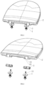
- a hinged structure for a toilet cover plate includes a fixed seat 1 fixedly arranged on the toilet and a cover plate 2 rotatably arranged on the fixed seat 1, the cover plate 2 is provided with a mounting hole 21, and a seat hinge assembly 3 for hinged the fixed seat 1 with the cover plate 2 is installed in the mounting hole 21, the seat hinge assembly 3 includes an oil core sleeve 31 fixedly arranged in the mounting hole 21.
- the seat hinge assembly 3 also includes a hinge shaft 32, the hinge shaft 32 includes an oil core part 321 rotatably arranged in the oil core sleeve 31 and a seat hinge part 322 inserted and matched with the connection column 11 on the fixed seat 1, and the oil core part 321 is integrally formed with the seat hinge part 322, the cover plate 2 is provided with an arc-shaped hole 22 communicated with the radial direction of the mounting hole 21.
- the seat hinge assembly 3 When the seat hinge assembly 3 is installed in the mounting hole 21, the seat hinge assembly 3 is clamped in the arc-shaped hole 22 through an annular elastic buckle 4, so that the seat hinge assembly 3 is fixed axially; the seat hinge part 322 and the oil core part 321 provided by the present disclosure are integrally formed, which can effectively reduce the coaxiality error of the seat hinge assembly, so as to reduce the mechanical fatigue of the buffer parts and prolong the service life.
- the annular elastic buckle 4 the disassembly and assembly of the seat hinge assembly 3 can be quickly completed, so as to realize the rotational installation between the cover plate 2 and the fixed seat 1.
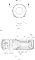
- a sealing cavity 310 for containing damping oil is formed between the oil core part 321 and the oil core sleeve 31.
- a spacer block 311 projecting radially inward is arranged on the inner wall of the oil core sleeve 31, which separates the sealing cavity 310 into a first cavity 312 and a second cavity 313, the middle part of the spacer block 311 is provided with a shaft hole which can adapt to the oil core part 321, and the oil core part 321 is fixedly connected with the limit column 5 by ultrasonic welding after passing through the shaft hole.
- the oil core part 321 passes through the shaft hole and is fixed with the limit column 5 by ultrasonic welding, which has high speed, high efficiency and low cost; at the same time, it eliminates the use of a large number of fixtures, adhesives or mechanical fasteners.
- the annular elastic buckle 4 includes an annular part 41 and a raised part 42 arranged on the end face of the annular part 41 and projecting outward towards the diameter of the annular part 41.
- the annular part 41 has an opening so that the annular part 41 is in an open ring, and the outer circumference of the seat hinge part 322 is provided with an annular groove 3221 for the annular part 41 to be sleeved in, and the outer circumference of the seat hinge part 322 is also provided with an avoidance slot 3222 communicated with the annular groove 3221 and the avoidance slot 3222 is configured to accommodate the raised part 42 entirely.
- the top of the raised part 42 is higher than the peripheral surface of the seat hinge part 322, so that the raised part 42 of the annular elastic buckle 4 is clamped in the arc-shaped hole 22 through the mounting hole 21 from outside to inside along the axis direction of the mounting hole 21 during assembly.
- the outer surface of the raised part 42 is a gentle inclined surface, which is convenient for the raised part 42 to be clamped into the arc-shaped hole 22 from outside to inside. During disassembly, the user needs to press the raised part 42 down to make it accommodate entirely in the avoidance slot 3222.
- the raised part 42 is clamped away from the arc-shaped hole 22, so as to facilitate the removal of the whole seat hinge assembly 3 from the mounting hole.
- the user can complete the fixation of the seat hinge assembly without using snap nails, decorative rings, snap ring and other parts.
- the annular elastic buckle makes the installation and disassembly of the damper more convenient.
- the inner side of the annular part 41 is provided with an insertion column 411
- the seat hinge part 322 is provided with an insertion hole 3223 located at the bottom of the annular groove 3221.
- the insertion hole 3223 is configured for the insertion of the insertion column 411.
- the inner side of the annular part 41 is also relatively symmetrically provided with a clamping block 412, and the seat hinge part 322 is provided with a clamping notch 3224 located at the bottom of the annular groove 3221 and clamped by the clamping block 412 respectively.
- the annular part 41 of the annular elastic buckle 4 is sleeved in the annular groove 3221, the annular part 41 is correspondingly clamped into the clamping notch 3224 through the clamping block 412, which can further increase the circumferential fixing stability of the annular elastic buckle 4 relative to the hinge shaft 32.
- the number of the raised parts 42 corresponds to the number of the avoidance slots 3222 and there are two raised parts 42.
- the two raised parts 42 are arranged along the circumferential direction of the annular part 41, so that when the cover plate 2 is in the open state or closed state, the arc-shaped hole 22 of the cover plate 2 can be switched to engage with at least one of the two raised parts 42.
- the number of the raised parts 42 is set to two, so that at least one raised part 42 can be clamped with the arc-shaped hole 22 when the cover plate 2 is overturned at a certain angle, so as to ensure the effectiveness of mechanical operation between various parts.
- the peripheral surface of the seat hinge part 322 is provided with an accommodation hole 3225 located between the two avoidance slots 3222, and the accommodation hole 3225 is configured for the insertion of the connection column 11.
- the connection column 11 is inserted into the accommodation hole 3225 and connected through the buckle mechanism 6.
- the buckle mechanism 6 includes a fastener 61, and the fastener 61 is provided with an insertion block 611.
- the end of the seat hinge part 322 is provided with a first accommodation slot 3226 communicated with the accommodation hole 3225, and the first accommodation slot 3226 is configured for the insertion of the insertion block 611.
- the insertion block 611 is provided with a clamping hole 6111 through the insertion block 611.
- the clamping hole 6111 has a fastening position and a tripping position.
- the clamping hole 6111 is formed by two circles with different diameters, and the position of the circle with small diameter is a fastening position, while the position of the circle with large diameter is the tripping position.
- connection column 11 is provided with an annular clamping groove 111, in the fastening state, the fastening position of the clamping hole 6111 is clamped into the annular clamping groove 111.
- a return spring 7 driving the return movement of the fastener 61 is arranged between the seat hinge part 322 and the insertion block 611 to realize the switching of the connection column 11 between different states.
- the fastener 61 is symmetrically provided with insertion strips 612, the sides of the insertion strip 612 facing to each other are respectively provided with a first hook 6121, the sides of the insertion strip 612 opposite to each other are respectively provided with a second hook 6122.
- the end of the seat hinge part 322 is provided with a second accommodation slot 3227 for the corresponding insertion of the insertion strip 612, and the second accommodation slot 3227 is provided with a third hook 3228 and a fourth hook 3229 corresponding to the first hook 6121 and the second hook 6122 respectively.
- connection column 11 When the connection column 11 is in the tripping position, the first hook 6121 and the third hook 3228 are engaged, and when the connection column is in the fastening position, the second hook 6122 and the fourth hook 3229 are engaged, the fastener 61 has different hooks for fastening in the tripping state and fastening state respectively, so as to realize the multi-level fastening of the fastener 61, so as to facilitate the disassembly and assembly of the connection column 11.
- the sides of the insertion strip 612 facing to each other are also provided with a tripping clamp boss 6123, and the connection column 11 is provided with an annular flange 112 located below the annular clamping groove 111, when the connection column 11 is in the tripping position, the first hook 6121 and the third hook 3228 are engaged.
- the annular flange 112 of the connection column 11 will push up the tripping clamp boss 6123 and push it towards both sides, so as to drive the insertion strip 612 to push towards both sides.
- the first hook 6121 will disengage from the engagement with the third hook 3228, at the same time, the fastener 61 moves under the action of the return spring 7, and the fastener 61 can drive the second hook 6122 to engage with the fourth hook 3229 during the return movement, so as to facilitate the next insertion and fastening of the connection column 11.
Landscapes
- Health & Medical Sciences (AREA)
- Public Health (AREA)
- Toilet Supplies (AREA)
- Closures For Containers (AREA)
- Pivots And Pivotal Connections (AREA)
Claims (9)
- Gelenkstruktur für eine Toilettenabdeckplatte, umfassend einen fest angeordneten Sitz (1), der fest an der Toilette angeordnet ist, und eine Abdeckplatte (2), die drehbar an dem fest angeordneten Sitz (1) angeordnet ist, wobei ein Montageloch (21) an der Abdeckplatte (2) angeordnet ist und eine Sitzgelenkbaugruppe (3) zum gelenkigen Verbinden des fest angeordneten Sitzes (1) und der Abdeckplatte (2) in dem Montageloch (21) installiert ist; wobei die Sitzgelenkbaugruppe (3) eine Ölkernhülse (31) umfasst, die fest in dem Montageloch (21) angeordnet ist, und die Sitzgelenkbaugruppe (3) ferner eine Gelenkwelle (32) umfasst, wobei die Gelenkwelle (32) einen Ölkernteil (321), der drehbar in der Ölkernhülse (31) angeordnet ist, und einen Sitzgelenkteil (322) umfasst, der eingeführt und mit der Verbindungssäule (11) an dem fest angeordneten Sitz (1) übereinstimmt, wobei der Ölkernteil (321) einstückig mit dem Sitzgelenkteil (322) gebildet ist; wobei die Abdeckplatte (2) mit einem bogenförmigen Loch (22) versehen ist, das in einer radialen Richtung mit dem Montageloch (21) in Verbindung steht; wobei die Sitzgelenkbaugruppe (3) durch eine ringförmige elastische Halterung (4) in dem bogenförmigen Loch (22) eingeklemmt ist, wenn die Sitzgelenkbaugruppe (3) in dem Montageloch (21) installiert ist, sodass die Sitzgelenkbaugruppe (3) axial fixiert ist; wobei ein Dichtungshohlraum (310) zum Aufnehmen von Dämpföl zwischen dem Ölkernteil (321) und der Ölkernhülse (31) gebildet ist; wobei die Innenwand der Ölkernhülse (31) mit einem Abstandhalterblock (311) versehen ist, der radial nach innen vorspringt, wobei der Abstandhalterblock (311) den Dichtungshohlraum (310) in einen ersten Hohlraum (312) und einen zweiten Hohlraum (313) unterteilt, und ein Wellenloch, das mit dem Ölkern (321) übereinstimmt, durch eine Mitte des Abstandhalterblocks (311) hindurch angeordnet ist, wobei der Ölkernteil (321) durch das Wellenloch verläuft und mittels Ultraschallschweißen fest mit der Begrenzungssäule (5) verbunden ist.
- Gelenkstruktur für eine Toilettenabdeckplatte nach Anspruch 1, dadurch gekennzeichnet, dass die ringförmige elastische Halterung (4) einen ringförmigen Teil (41) und einen erhöhten Teil (42) umfasst, der an einer Endfläche des ringförmigen Teils (41) angeordnet ist und in einer radialen Richtung nach außen zu dem ringförmigen Teil (41) hin vorspringt; wobei ein Außenumfang des Sitzgelenkteils (322) mit einer ringförmigen Nut (3221) versehen ist, in die der ringförmige Teil (41) eingesetzt ist, der Außenumfang des Sitzgelenkteils (322) ferner mit einem Ausweichschlitz (3222) versehen ist, der mit der ringförmigen Nut (3221) in Verbindung steht, und der Ausweichschlitz zum vollständigen Aufnehmen des erhöhten Teils (42) konfiguriert ist; wobei, wenn der ringförmige Teil (41) der ringförmigen elastischen Halterung (4) auf einen Außenumfang der ringförmigen Nut (3221) an der Gelenkwelle (322) gesetzt ist, eine Oberseite des erhöhten Teils (42) höher als eine Außenumfangsfläche des Sitzgelenkteils (322) ist, sodass der erhöhte Teil (42) der ringförmigen elastischen Halterung (4) während der Montage durch das Montageloch (21) in axialer Richtung des Montagelochs (21) von außen nach innen in dem bogenförmigen Loch (22) eingeklemmt wird.
- Gelenkstruktur für eine Toilettenabdeckplatte nach Anspruch 2, dadurch gekennzeichnet, dass eine Einführsäule (411) auf einer Innenseite des ringförmigen Teils (41) angeordnet ist und ein Einführloch (3223), das sich an einem Boden der ringförmigen Nut (3221) befindet und zum Einführen der Einführsäule (411) konfiguriert ist, an dem Sitzgelenkteil (322) angeordnet ist; wobei, wenn der ringförmige Teil (41) der ringförmigen elastischen Halterung (4) in die ringförmigen Nut (3221) eingesetzt wird, der ringförmige Teil (41) durch die Einführsäule (411) in das Einführloch (3223) eingeführt wird.
- Gelenkstruktur für eine Toilettenabdeckplatte nach Anspruch 3, dadurch gekennzeichnet, dass die Innenseite des ringförmigen Teils (41) symmetrisch mit Klemmblöcken (412) versehen ist und der Sitzgelenkteil (322) mit einer Klemmaussparung (3224) versehen ist, die sich am Boden der ringförmigen Nut (3221) befindet und zum Einklemmen jeweils eines Klemmblocks (412) konfiguriert ist; wobei, wenn der ringförmige Teil (41) der ringförmigen elastischen Halterung (4) in die ringförmigen Nut (3221) eingesetzt wird, der ringförmige Teil (41) durch den Klemmblock (412) in der Klemmaussparung (3224) eingeklemmt wird.
- Gelenkstruktur für eine Toilettenabdeckplatte nach Anspruch 3, dadurch gekennzeichnet, dass die Anzahl der erhöhten Teile (42) der Anzahl der Ausweichschlitze (3222) entspricht und zwei erhöhte Teile vorliegen, wobei die beiden erhöhten Teile (42) entlang der Umfangsrichtung des ringförmigen Teils (41) angeordnet sind, sodass, wenn sich die Abdeckplatte (2) in einem offenen oder geschlossenen Zustand befindet, das bogenförmige Loch (22) an der Abdeckplatte (2) zum Eingriff mit wenigstens einem der beiden erhöhten Teile (42) wechselt.
- Gelenkstruktur für eine Toilettenabdeckplatte nach Anspruch 5, dadurch gekennzeichnet, dass der Außenumfang des Sitzgelenkteils (322) mit einem Aufnahmeloch (3225) zwischen den beiden Ausweichschlitzen (3222) versehen ist, um die Verbindungssäule (11) aufzunehmen, und die Verbindungssäule (11) in das Aufnahmeloch (3225) eingeführt und durch einen Halterungsmechanismus (6) verbunden ist.
- Gelenkstruktur für eine Toilettenabdeckplatte nach Anspruch 6, dadurch gekennzeichnet, dass der Rastmechanismus (6) ein Befestigungselement (61) umfasst, ein Einführblock (611) an dem Befestigungselement (61) angeordnet ist und ein Ende des Sitzgelenkteils (322) mit einem ersten Aufnahmeschlitz (3226) versehen ist, der mit dem Aufnahmeloch (3225) in Verbindung steht, der zum Einführen des Einführblocks (611) konfiguriert ist; wobei der Einführblock (611) mit einem Klemmloch (6111) durch den Einführblock (611) versehen ist und das Klemmloch mit einer Befestigungsstellung und einer Auslösestellung versehen ist; wobei sich die Verbindungssäule (11) in der Auslösestellung befindet, wenn die Verbindungssäule (11) durch das Aufnahmeloch (3225) in die Auslösestellung des Klemmlochs (6111) eingeführt ist, und sich die Verbindungssäule (11) in der Befestigungsstellung befindet, wenn die Verbindungssäule (11) durch das Aufnahmeloch (3225) in die Befestigungsstellung des Klemmlochs (6111) eingeführt ist; wobei eine Rückstellfeder (7), die eine Rückstellbewegung des Befestigungselements (61) bewirkt, zwischen dem Sitzgelenkteil (322) und dem Einführblock (611) angeordnet ist, um einen Wechsel der Verbindungssäule (11) zwischen unterschiedlichen Zuständen zu bewirken.
- Gelenkstruktur für eine Toilettenabdeckplatte nach Anspruch 7, dadurch gekennzeichnet, dass das Befestigungselement (61) symmetrisch mit Einführstreifen (612) versehen ist, wobei die einander zugewandten Seiten der Einführstreifen (612) jeweils mit einem ersten Haken (6121) versehen sind und die voneinander abgewandten Seiten der Einführstreifen (612) jeweils mit einem zweiten Haken (6122) versehen sind, wobei das Ende des Sitzgelenkteils (322) mit einem zweiten Aufnahmeschlitz (3227) zum Einführen eines entsprechenden Einführstreifens (612) versehen ist und der zweite Aufnahmeschlitz (3227) mit einem dritten Haken (3228) und einem vierten Haken (3229) versehen ist, die dem ersten Haken (6121) und dem zweiten Haken (6122) entsprechen; wobei der erste Haken (6121) und der dritte Haken (3228) in Eingriff stehen, wenn sich die Verbindungssäule (11) in der Auslösestellung befindet, und der zweite Haken (6122) und der vierte Haken (3229) in Eingriff stehen, wenn sich die Verbindungssäule (11) in der Befestigungsstellung befindet.
- Gelenkstruktur für eine Toilettenabdeckplatte nach einem der Ansprüche 2 bis 8, dadurch gekennzeichnet, dass der ringförmige Teil (41) mit einer Öffnung versehen ist, sodass der ringförmige Teil (41) ein nicht geschlossener Ring ist.
Applications Claiming Priority (1)
| Application Number | Priority Date | Filing Date | Title |
|---|---|---|---|
| CN202121150059.0U CN215127933U (zh) | 2021-05-26 | 2021-05-26 | 一种用于座便器盖板的铰接结构 |
Publications (3)
| Publication Number | Publication Date |
|---|---|
| EP4094653A1 EP4094653A1 (de) | 2022-11-30 |
| EP4094653C0 EP4094653C0 (de) | 2023-07-12 |
| EP4094653B1 true EP4094653B1 (de) | 2023-07-12 |
Family
ID=79372248
Family Applications (1)
| Application Number | Title | Priority Date | Filing Date |
|---|---|---|---|
| EP22164495.8A Active EP4094653B1 (de) | 2021-05-26 | 2022-03-25 | Scharnierstruktur für toilettendeckelplatte |
Country Status (3)
| Country | Link |
|---|---|
| EP (1) | EP4094653B1 (de) |
| CN (1) | CN215127933U (de) |
| ES (1) | ES2952323T3 (de) |
Families Citing this family (1)
| Publication number | Priority date | Publication date | Assignee | Title |
|---|---|---|---|---|
| CN118633854A (zh) | 2024-05-11 | 2024-09-13 | 厦门博维尔卫浴有限公司 | 一种马桶转轴连接结构 |
Family Cites Families (2)
| Publication number | Priority date | Publication date | Assignee | Title |
|---|---|---|---|---|
| CN201767898U (zh) | 2010-04-28 | 2011-03-23 | 周裕佳 | 坐便器盖板铰链结构 |
| CN203762997U (zh) * | 2014-03-21 | 2014-08-13 | 厦门豪帝卫浴工业有限公司 | 一种马桶盖板无按钮直立拆装机构 |
-
2021
- 2021-05-26 CN CN202121150059.0U patent/CN215127933U/zh active Active
-
2022
- 2022-03-25 ES ES22164495T patent/ES2952323T3/es active Active
- 2022-03-25 EP EP22164495.8A patent/EP4094653B1/de active Active
Also Published As
| Publication number | Publication date |
|---|---|
| ES2952323T3 (es) | 2023-10-30 |
| CN215127933U (zh) | 2021-12-14 |
| EP4094653C0 (de) | 2023-07-12 |
| EP4094653A1 (de) | 2022-11-30 |
Similar Documents
| Publication | Publication Date | Title |
|---|---|---|
| CN206560311U (zh) | 电压力锅和电压力锅的上盖组件 | |
| AU2011296477B8 (en) | Tensioner with expanding spring for radial frictional damping | |
| EP4094653A1 (de) | Scharnierstruktur für toilettendeckelplatte | |
| CN106523791B (zh) | 车用管线安装管夹 | |
| CN113107301B (zh) | 离合自动开门装置及冰箱 | |
| US5142740A (en) | Toilet covering hinge assembly | |
| US11879477B2 (en) | Fan lamp | |
| CN110924778A (zh) | 一种冰箱 | |
| US11064850B2 (en) | Toilet seat assembly installation structure convenient for disassembly and assembly | |
| GB2333979A (en) | Drilling chuck | |
| EP4094654B1 (de) | Scharnierstruktur für toilettendeckelplatte | |
| EP4094655B1 (de) | Selbstsichernde struktur für einen toilettensitzstossdämpfer | |
| US4197596A (en) | Cover for toilet bowls | |
| CN109707264B (zh) | 离合自动开门装置及冰箱 | |
| CN215632222U (zh) | 一种隐藏基座式执手结构 | |
| CN107432667A (zh) | 电压力锅和电压力锅的上盖组件 | |
| CN217218877U (zh) | 一种马桶座盖的快拆装置 | |
| CN109708399B (zh) | 离合自动开门装置及冰箱 | |
| EP4094652A1 (de) | Selbstverriegelnde struktur für toilettenstossdämpfer | |
| CN214664795U (zh) | 一种空调器 | |
| JPH1047404A (ja) | 緩衝装置 | |
| CN110595141B (zh) | 离合自动开门装置及冰箱 | |
| CN217374630U (zh) | 童车车轮的快拆结构 | |
| KR940701513A (ko) | 마찰클러치 구동판 | |
| CN219316649U (zh) | 一种执手结构及无基座执手 |
Legal Events
| Date | Code | Title | Description |
|---|---|---|---|
| PUAI | Public reference made under article 153(3) epc to a published international application that has entered the european phase |
Free format text: ORIGINAL CODE: 0009012 |
|
| STAA | Information on the status of an ep patent application or granted ep patent |
Free format text: STATUS: REQUEST FOR EXAMINATION WAS MADE |
|
| 17P | Request for examination filed |
Effective date: 20220325 |
|
| AK | Designated contracting states |
Kind code of ref document: A1 Designated state(s): AL AT BE BG CH CY CZ DE DK EE ES FI FR GB GR HR HU IE IS IT LI LT LU LV MC MK MT NL NO PL PT RO RS SE SI SK SM TR |
|
| RIN1 | Information on inventor provided before grant (corrected) |
Inventor name: MA, JIAFU Inventor name: LIANG, WEINAN Inventor name: ZHANG, HAI Inventor name: HUANG, HAOJIA Inventor name: ZHOU, WENHUI |
|
| GRAP | Despatch of communication of intention to grant a patent |
Free format text: ORIGINAL CODE: EPIDOSNIGR1 |
|
| STAA | Information on the status of an ep patent application or granted ep patent |
Free format text: STATUS: GRANT OF PATENT IS INTENDED |
|
| RIC1 | Information provided on ipc code assigned before grant |
Ipc: A47K 13/24 20060101ALN20230119BHEP Ipc: A47K 13/12 20060101AFI20230119BHEP |
|
| INTG | Intention to grant announced |
Effective date: 20230210 |
|
| GRAS | Grant fee paid |
Free format text: ORIGINAL CODE: EPIDOSNIGR3 |
|
| GRAA | (expected) grant |
Free format text: ORIGINAL CODE: 0009210 |
|
| STAA | Information on the status of an ep patent application or granted ep patent |
Free format text: STATUS: THE PATENT HAS BEEN GRANTED |
|
| AK | Designated contracting states |
Kind code of ref document: B1 Designated state(s): AL AT BE BG CH CY CZ DE DK EE ES FI FR GB GR HR HU IE IS IT LI LT LU LV MC MK MT NL NO PL PT RO RS SE SI SK SM TR |
|
| REG | Reference to a national code |
Ref country code: CH Ref legal event code: EP |
|
| REG | Reference to a national code |
Ref country code: IE Ref legal event code: FG4D |
|
| REG | Reference to a national code |
Ref country code: DE Ref legal event code: R096 Ref document number: 602022000192 Country of ref document: DE |
|
| U01 | Request for unitary effect filed |
Effective date: 20230717 |
|
| U07 | Unitary effect registered |
Designated state(s): AT BE BG DE DK EE FI FR IT LT LU LV MT NL PT SE SI Effective date: 20230725 |
|
| REG | Reference to a national code |
Ref country code: ES Ref legal event code: FG2A Ref document number: 2952323 Country of ref document: ES Kind code of ref document: T3 Effective date: 20231030 |
|
| REG | Reference to a national code |
Ref country code: LT Ref legal event code: MG9D |
|
| PG25 | Lapsed in a contracting state [announced via postgrant information from national office to epo] |
Ref country code: GR Free format text: LAPSE BECAUSE OF FAILURE TO SUBMIT A TRANSLATION OF THE DESCRIPTION OR TO PAY THE FEE WITHIN THE PRESCRIBED TIME-LIMIT Effective date: 20231013 |
|
| PG25 | Lapsed in a contracting state [announced via postgrant information from national office to epo] |
Ref country code: IS Free format text: LAPSE BECAUSE OF FAILURE TO SUBMIT A TRANSLATION OF THE DESCRIPTION OR TO PAY THE FEE WITHIN THE PRESCRIBED TIME-LIMIT Effective date: 20231112 |
|
| PG25 | Lapsed in a contracting state [announced via postgrant information from national office to epo] |
Ref country code: RS Free format text: LAPSE BECAUSE OF FAILURE TO SUBMIT A TRANSLATION OF THE DESCRIPTION OR TO PAY THE FEE WITHIN THE PRESCRIBED TIME-LIMIT Effective date: 20230712 Ref country code: NO Free format text: LAPSE BECAUSE OF FAILURE TO SUBMIT A TRANSLATION OF THE DESCRIPTION OR TO PAY THE FEE WITHIN THE PRESCRIBED TIME-LIMIT Effective date: 20231012 Ref country code: IS Free format text: LAPSE BECAUSE OF FAILURE TO SUBMIT A TRANSLATION OF THE DESCRIPTION OR TO PAY THE FEE WITHIN THE PRESCRIBED TIME-LIMIT Effective date: 20231112 Ref country code: HR Free format text: LAPSE BECAUSE OF FAILURE TO SUBMIT A TRANSLATION OF THE DESCRIPTION OR TO PAY THE FEE WITHIN THE PRESCRIBED TIME-LIMIT Effective date: 20230712 Ref country code: GR Free format text: LAPSE BECAUSE OF FAILURE TO SUBMIT A TRANSLATION OF THE DESCRIPTION OR TO PAY THE FEE WITHIN THE PRESCRIBED TIME-LIMIT Effective date: 20231013 |
|
| PG25 | Lapsed in a contracting state [announced via postgrant information from national office to epo] |
Ref country code: PL Free format text: LAPSE BECAUSE OF FAILURE TO SUBMIT A TRANSLATION OF THE DESCRIPTION OR TO PAY THE FEE WITHIN THE PRESCRIBED TIME-LIMIT Effective date: 20230712 |
|
| REG | Reference to a national code |
Ref country code: DE Ref legal event code: R097 Ref document number: 602022000192 Country of ref document: DE |
|
| U20 | Renewal fee for the european patent with unitary effect paid |
Year of fee payment: 3 Effective date: 20240318 |
|
| PG25 | Lapsed in a contracting state [announced via postgrant information from national office to epo] |
Ref country code: SM Free format text: LAPSE BECAUSE OF FAILURE TO SUBMIT A TRANSLATION OF THE DESCRIPTION OR TO PAY THE FEE WITHIN THE PRESCRIBED TIME-LIMIT Effective date: 20230712 Ref country code: RO Free format text: LAPSE BECAUSE OF FAILURE TO SUBMIT A TRANSLATION OF THE DESCRIPTION OR TO PAY THE FEE WITHIN THE PRESCRIBED TIME-LIMIT Effective date: 20230712 Ref country code: CZ Free format text: LAPSE BECAUSE OF FAILURE TO SUBMIT A TRANSLATION OF THE DESCRIPTION OR TO PAY THE FEE WITHIN THE PRESCRIBED TIME-LIMIT Effective date: 20230712 Ref country code: SK Free format text: LAPSE BECAUSE OF FAILURE TO SUBMIT A TRANSLATION OF THE DESCRIPTION OR TO PAY THE FEE WITHIN THE PRESCRIBED TIME-LIMIT Effective date: 20230712 |
|
| PLBE | No opposition filed within time limit |
Free format text: ORIGINAL CODE: 0009261 |
|
| STAA | Information on the status of an ep patent application or granted ep patent |
Free format text: STATUS: NO OPPOSITION FILED WITHIN TIME LIMIT |
|
| 26N | No opposition filed |
Effective date: 20240415 |
|
| PG25 | Lapsed in a contracting state [announced via postgrant information from national office to epo] |
Ref country code: MC Free format text: LAPSE BECAUSE OF FAILURE TO SUBMIT A TRANSLATION OF THE DESCRIPTION OR TO PAY THE FEE WITHIN THE PRESCRIBED TIME-LIMIT Effective date: 20230712 |
|
| PG25 | Lapsed in a contracting state [announced via postgrant information from national office to epo] |
Ref country code: MC Free format text: LAPSE BECAUSE OF FAILURE TO SUBMIT A TRANSLATION OF THE DESCRIPTION OR TO PAY THE FEE WITHIN THE PRESCRIBED TIME-LIMIT Effective date: 20230712 |
|
| PG25 | Lapsed in a contracting state [announced via postgrant information from national office to epo] |
Ref country code: IE Free format text: LAPSE BECAUSE OF NON-PAYMENT OF DUE FEES Effective date: 20240325 |
|
| PG25 | Lapsed in a contracting state [announced via postgrant information from national office to epo] |
Ref country code: IE Free format text: LAPSE BECAUSE OF NON-PAYMENT OF DUE FEES Effective date: 20240325 |
|
| U20 | Renewal fee for the european patent with unitary effect paid |
Year of fee payment: 4 Effective date: 20250226 |
|
| PGFP | Annual fee paid to national office [announced via postgrant information from national office to epo] |
Ref country code: ES Payment date: 20250404 Year of fee payment: 4 |
|
| PG25 | Lapsed in a contracting state [announced via postgrant information from national office to epo] |
Ref country code: CY Free format text: LAPSE BECAUSE OF FAILURE TO SUBMIT A TRANSLATION OF THE DESCRIPTION OR TO PAY THE FEE WITHIN THE PRESCRIBED TIME-LIMIT; INVALID AB INITIO Effective date: 20220325 |
|
| REG | Reference to a national code |
Ref country code: CH Ref legal event code: H13 Free format text: ST27 STATUS EVENT CODE: U-0-0-H10-H13 (AS PROVIDED BY THE NATIONAL OFFICE) Effective date: 20251024 |
|
| PG25 | Lapsed in a contracting state [announced via postgrant information from national office to epo] |
Ref country code: TR Free format text: LAPSE BECAUSE OF FAILURE TO SUBMIT A TRANSLATION OF THE DESCRIPTION OR TO PAY THE FEE WITHIN THE PRESCRIBED TIME-LIMIT Effective date: 20230712 |
|
| PG25 | Lapsed in a contracting state [announced via postgrant information from national office to epo] |
Ref country code: CH Free format text: LAPSE BECAUSE OF NON-PAYMENT OF DUE FEES Effective date: 20250331 |
|
| U20 | Renewal fee for the european patent with unitary effect paid |
Year of fee payment: 5 Effective date: 20260214 |
|
| PGFP | Annual fee paid to national office [announced via postgrant information from national office to epo] |
Ref country code: GB Payment date: 20260226 Year of fee payment: 5 |