EP4094626B1 - Tablar mit steckbaren aufbauten - Google Patents
Tablar mit steckbaren aufbauten Download PDFInfo
- Publication number
- EP4094626B1 EP4094626B1 EP22163976.8A EP22163976A EP4094626B1 EP 4094626 B1 EP4094626 B1 EP 4094626B1 EP 22163976 A EP22163976 A EP 22163976A EP 4094626 B1 EP4094626 B1 EP 4094626B1
- Authority
- EP
- European Patent Office
- Prior art keywords
- leg
- leg section
- profile
- base
- shelf according
- Prior art date
- Legal status (The legal status is an assumption and is not a legal conclusion. Google has not performed a legal analysis and makes no representation as to the accuracy of the status listed.)
- Active
Links
Images


Classifications
-
- B—PERFORMING OPERATIONS; TRANSPORTING
- B65—CONVEYING; PACKING; STORING; HANDLING THIN OR FILAMENTARY MATERIAL
- B65D—CONTAINERS FOR STORAGE OR TRANSPORT OF ARTICLES OR MATERIALS, e.g. BAGS, BARRELS, BOTTLES, BOXES, CANS, CARTONS, CRATES, DRUMS, JARS, TANKS, HOPPERS, FORWARDING CONTAINERS; ACCESSORIES, CLOSURES, OR FITTINGS THEREFOR; PACKAGING ELEMENTS; PACKAGES
- B65D19/00—Pallets or like platforms, with or without side walls, for supporting loads to be lifted or lowered
- B65D19/38—Details or accessories
-
- A—HUMAN NECESSITIES
- A47—FURNITURE; DOMESTIC ARTICLES OR APPLIANCES; COFFEE MILLS; SPICE MILLS; SUCTION CLEANERS IN GENERAL
- A47B—TABLES; DESKS; OFFICE FURNITURE; CABINETS; DRAWERS; GENERAL DETAILS OF FURNITURE
- A47B96/00—Details of cabinets, racks or shelf units not covered by a single one of groups A47B43/00 - A47B95/00; General details of furniture
- A47B96/02—Shelves
- A47B96/025—Shelves with moving elements, e.g. movable extensions or link elements
-
- A—HUMAN NECESSITIES
- A47—FURNITURE; DOMESTIC ARTICLES OR APPLIANCES; COFFEE MILLS; SPICE MILLS; SUCTION CLEANERS IN GENERAL
- A47B—TABLES; DESKS; OFFICE FURNITURE; CABINETS; DRAWERS; GENERAL DETAILS OF FURNITURE
- A47B88/00—Drawers for tables, cabinets or like furniture; Guides for drawers
- A47B88/90—Constructional details of drawers
- A47B88/969—Drawers having means for organising or sorting the content
-
- B—PERFORMING OPERATIONS; TRANSPORTING
- B65—CONVEYING; PACKING; STORING; HANDLING THIN OR FILAMENTARY MATERIAL
- B65D—CONTAINERS FOR STORAGE OR TRANSPORT OF ARTICLES OR MATERIALS, e.g. BAGS, BARRELS, BOTTLES, BOXES, CANS, CARTONS, CRATES, DRUMS, JARS, TANKS, HOPPERS, FORWARDING CONTAINERS; ACCESSORIES, CLOSURES, OR FITTINGS THEREFOR; PACKAGING ELEMENTS; PACKAGES
- B65D19/00—Pallets or like platforms, with or without side walls, for supporting loads to be lifted or lowered
- B65D19/38—Details or accessories
- B65D19/40—Elements for spacing platforms from supporting surface
-
- A—HUMAN NECESSITIES
- A47—FURNITURE; DOMESTIC ARTICLES OR APPLIANCES; COFFEE MILLS; SPICE MILLS; SUCTION CLEANERS IN GENERAL
- A47B—TABLES; DESKS; OFFICE FURNITURE; CABINETS; DRAWERS; GENERAL DETAILS OF FURNITURE
- A47B2210/00—General construction of drawers, guides and guide devices
- A47B2210/01—Drawer chassis or frame
-
- B—PERFORMING OPERATIONS; TRANSPORTING
- B65—CONVEYING; PACKING; STORING; HANDLING THIN OR FILAMENTARY MATERIAL
- B65D—CONTAINERS FOR STORAGE OR TRANSPORT OF ARTICLES OR MATERIALS, e.g. BAGS, BARRELS, BOTTLES, BOXES, CANS, CARTONS, CRATES, DRUMS, JARS, TANKS, HOPPERS, FORWARDING CONTAINERS; ACCESSORIES, CLOSURES, OR FITTINGS THEREFOR; PACKAGING ELEMENTS; PACKAGES
- B65D2519/00—Pallets or like platforms, with or without side walls, for supporting loads to be lifted or lowered
- B65D2519/00004—Details relating to pallets
- B65D2519/00258—Overall construction
- B65D2519/00263—Overall construction of the pallet
- B65D2519/00273—Overall construction of the pallet made of more than one piece
Definitions
- the invention relates to a shelf, in particular a drawer shelf, according to the preamble of claim 1.
- a shelf can in particular be the base of a furniture element, for example a drawer.
- Such a tray is, for example, DE 11 02 545 B or through DE 20 2019 107232 U1 became known.
- DE 11 02 545 B discloses a profiled frame consisting of four frame parts connected at the corners, each formed integrally from a solid profile piece.
- the frame parts have an upwardly open profile groove for accommodating glass panels.
- a supporting frame which is composed of four frame parts, each of which is designed as a hollow chamber profile piece and has an upwardly open profile groove for receiving a boundary wall.
- the present invention is based on the object of further simplifying a tray of the type mentioned above and producing it as cost-effectively as possible. Furthermore, the base plate and the structural elements should be replaceable during the tray's service life.
- the double-layered lower or upper leg section significantly increases the stability and torsional rigidity of the profile frame.
- the two sheet metal layers of the lower or upper leg section can be attached to one another, in particular glued or welded.
- the bottom leg can preferably be bent by approximately 90° from the inner sheet metal layer of the lower or upper leg section.
- the structural elements can be made of metal, wood, plastic or glass, for example.
- the profile frame has a continuously circumferential bottom leg and/or a continuously circumferential outer leg.
- the base leg is bent in a Z-shape and comprises a higher outer leg section adjoining the outer leg and a lower inner leg section, with the base plate resting on the higher outer leg section or the lower inner leg section.
- a pull-out guide can advantageously be accommodated in the corner area between the lower inner leg section and the lower leg section.
- the base plate rests on the base leg either directly or via at least one spacer.
- the height of the selected spacers can be adjusted to create a desired positive or negative height difference between the top of the base plate and the top edge of the outer leg.
- corner posts are inserted into the joint in the corner areas of the profile frame and fastened to the base leg, in particular clamped or screwed.
- a wall element can be inserted between two corner posts and fixed to it, for example, by means of a fastening element, in a force-fitting or form-fitting manner.
- the wall elements can be, for example, side, rear or front walls of a drawer. These walls can extend completely around the base plate as a complete frame. It is also possible for the walls to be provided only on some end faces of the base plate or to extend only partially along one or more end faces.
- the wall elements can also be inserted into the joint.
- a floor profile strip is inserted and clamped into the joint, the upper side of which covers the joint, particularly flush with the upper side of the floor slab. Wall elements can then rest on the floor profile strip or be inserted into a joint of the floor profile strip.
- a floor profile strip is preferably made of plastic.
- Various color designs for the floor profile strips are conceivable.
- a pull-out guide is arranged on each of two opposite sides of the profile frame in the corner area between the base leg and the lower leg section, particularly in the corner area between the deeper inner leg section and the lower leg section, and is attached to the profile frame.
- the two pull-out guides are concealed by the lower leg section and are therefore not visible from the outside.
- the tray 1 shown comprises a rectangular base plate 2 and a rectangular profile frame 3 surrounding the base plate 2.
- the profile frame 3 has an inner, all-round (horizontal) base leg 4, on which the base plate 2 rests and is fastened, and a circumferential (vertical) outer leg 5 adjoining the base leg 4 on the outside, which is aligned at right angles to the base leg 4.
- the base plate 2 can, for example, be screwed or glued to the base leg 4.
- the outer leg 5 has an upper leg section 6 extending above the base leg 4 and a lower leg section 7 extending below the base leg 4.
- the upper leg section 6 can, as in Fig. 1b shown, end at the same height as the top of the base plate 2, but alternatively also end below or above the top of the base plate 2.
- the base plate 2 and the outer leg 5 are horizontally spaced from one another in order to form an upwardly open, circumferential joint 8 for the insertion and fastening of structural elements, e.g. corner posts 9 .
- the profile frame 3 can be formed by a single profile part which is connected to form a frame, or by several profile parts, each with the same or different profile cross-sections, which are connected to form a frame.
- Fig. 2 shows a possible profile cross-section of the profile frame 3 in the form of a folded metal sheet.
- the metal sheet is bent by 180° at the lower edge 10a of the lower leg section 7 in order to form the lower leg section 7 in two layers with an inner and an outer sheet layer 7 1 , 7 2 .
- the metal sheet Starting from its one longitudinal edge, which forms the upper edge of the upper leg section 6, the metal sheet extends vertically downwards to form the vertical upper leg section 6 and the vertical inner sheet layer 7 2 , and is bent at the lower edge 10a of the lower leg section 7 bent inwards by 180° to form the vertical inner sheet metal layer 7 1.
- the two sheet metal layers 7 1 , 7 2 lie parallel to one another and can be glued or spot-welded to one another on the inside.
- the horizontal base leg 4 is bent outwards by 90° and then folded in a Z shape to form a higher horizontal, outer leg section 4 1 adjacent to the outer leg 5 and a deeper horizontal, inner leg section 4 2.
- the inner edge of the inner leg section 4 2 which defines the frame opening of the profile frame 3, is thus formed by the other longitudinal edge of the metal profile.
- the entire profile frame 3 can be formed from a single sheet metal blank by bending and then connected to form a closed frame.
- the metal sheet can also be bent by 180° at the upper edge 10b of the upper leg section 6 in order to form the upper leg section 6 in two layers with an inner and an outer sheet layer.
- the base plate 2 lies on the base leg 4 either directly on the higher or the lower leg section 4 1 , 4 2 or, as in Fig. 1b shown, by means of spacers 11.
- the height of the selected spacers 11 can be used to set a desired positive or negative height difference between the top of the base plate 2 and the upper edge of the outer leg 5. In Fig. 1b the spacers 11 rest on the inner leg section 4 2 .
- the assembly of the corner post 9 on the profile frame 3 is shown, here only as an example on a profile frame with the Fig. 2 shown profile cross-section.
- the corner post 9 is an upright rectangular angle with two angle legs 12 , which are each extended in the foot area on their opposite sides by a downwardly open hook 13.
- the base leg 4 On both sides of the frame corner, the base leg 4, in the illustrated embodiment the outer leg section 4 1 , has a floor opening 14.
- the corner post 4 is placed diagonally to the base leg 4 and inserted with its two hooks 13 into the two floor openings 14.
- Corner post 9 is tilted vertically until the corner 15 of the corner post 9 rests against the frame corner 16 of the profile frame 3 and the hooks 13 are clamped to the base leg 4. Finally, the corner post 9 can be secured in this vertical position using a securing element, e.g., a screw 17 .
- a securing element e.g., a screw 17 .
- a floor profile strip 18 is inserted into the joint 8, the upper side of which profile covers the joint 8.
- the floor profile strip 18 has a profile leg 19 which runs, for example, obliquely to the upper side of the profile and which is clamped in the joint 8 on the floor panel 2.
- a (drawer) pull-out guide 20 is arranged on each of two opposite frame sides of the profile frame 3 in the corner area between the base leg 4 and the lower leg section 7, in the illustrated embodiment between the deeper inner leg section 4 2 and the lower leg section 7, and is fastened to the profile frame 3.
- the pull-out guides 20 are concealed by the lower leg section 7 and are therefore not visible from the outside.
- the wall elements 21 can rest on the floor profile strip 18.
- the bottom leg 4 and the outer leg 5 can also be designed to be circumferential only in sections.
Landscapes
- Engineering & Computer Science (AREA)
- Mechanical Engineering (AREA)
- Assembled Shelves (AREA)
- Pallets (AREA)
- Furniture Connections (AREA)
Description
- Die Erfindung betrifft ein Tablar, insbesondere Schubladentablar, gemäß dem Oberbegriff von Anspruch 1. Bei einem Tablar kann es sich insbesondere um den Boden eines Möbelelements, beispielsweise einer Schublade handeln.
- Ein solches Tablar ist beispielsweise durch die
DE 11 02 545 B oder durchDE 20 2019 107232 U1 bekannt geworden. -
DE 11 02 545 B offenbart einen Fassungsprofilrahmen aus vier an den Ecken miteinander verbundenen Rahmenteilen, die jeweils einstückig aus einem massiven Profilstück gebildet sind. Die Rahmenteile haben eine nach oben offene Profilnut zur Aufnahme von Glasplatten. -
DE 20 2019 107232 U1 offenbart ein rahmenförmiges Profil in Form eines Blechs, das mehrmals um 90° abgewinkelt ist, um eine nach oben offene, U-förmige Profilnut zur Aufnahme von Aufbauelementen auszubilden. - Aus
EP 0 078 466 A2 ist ein Tragrahmen bekannt, der aus vier Rahmenteilen zusammengesetzt ist, welche jeweils als Hohlkammerprofilstück ausgebildet sind und eine nach oben offene Profilnut zur Aufnahme einer Begrenzungswand aufweisen. - Der vorliegenden Erfindung liegt die Aufgabe zugrunde, ein Tablar der eingangs genannten Art weiter zu vereinfachen und möglichst kostengünstig herzustellen. Ebenfalls sollen während der Nutzungszeit des Tablars die Bodenplatte und die Aufbauelemente austauschbar sein.
- Diese Aufgabe wird erfindungsgemäß durch ein Tablar mit den Merkmalen von Anspruch 1 gelöst. Durch den doppellagigen unteren oder oberen Schenkelabschnitt sind die Stabilität und Verwindungssteifigkeit des Profilrahmens deutlich erhöht. Die beiden Blechlagen des unteren oder oberen Schenkelabschnitts können aneinander befestigt sein, insbesondere miteinander verklebt oder verschweißt sein. Der Bodenschenkel kann bevorzugt um ca. 90° von der inneren Blechlage des unteren bzw. oberen Schenkelabschnitts umgebogen sein.
- Die Aufbauelemente können beispielsweise aus Metall, Holzwerkstoff, Kunststoff oder Glas sein.
- Besonders bevorzugt weist der Profilrahmen einen ringsum durchgehend umlaufenden Bodenschenkel und/oder einen ringsum durchgehend umlaufenden Außenschenkel auf.
- Besonders bevorzugt ist der Bodenschenkel Z-förmig abgekantet und umfasst einen sich an den Außenschenkel anschließenden, höheren äußeren Schenkelabschnitt und einen tieferen inneren Schenkelabschnitt, wobei die Bodenplatte auf dem höheren äußeren Schenkelabschnitt oder dem tieferen inneren Schenkelabschnitt aufliegt. Im Eckbereich zwischen dem tieferen inneren Schenkelabschnitt und dem unteren Schenkelabschnitt kann vorteilhaft eine Ausziehführung untergebracht werden.
- Die Bodenplatte liegt entweder unmittelbar oder mittels mindestens eines Abstandshalters auf dem Bodenschenkel auf. Über die Höhe der gewählten Abstandshalter kann eine gewünschte, positive oder negative Höhendifferenz zwischen der Oberseite der Bodenplatte und der Oberkante des Außenschenkels beliebig eingestellt werden.
- Vorzugsweise sind in den Eckbereichen des Profilrahmens Eckpfosten in die Fuge eingesetzt und am Bodenschenkel befestigt, insbesondere festgeklemmt oder festgeschraubt. Zwischen zwei Eckpfosten kann ein Wandelement eingesetzt und daran z.B. mittels eines Befestigungselements kraft- oder formschlüssig fixiert sein. Als Wandelemente können beispielsweise Seiten-, Rück- oder Frontwände einer Schublade vorgesehen sein. Diese Wände können sich dabei als kompletter Rahmen vollständig um die Bodenplatte herum erstrecken. Es ist auch möglich, dass die Wände nur an manchen Stirnseiten der Bodenplatte vorgesehen sind oder sich nur teilweise entlang einer oder mehrerer Stirnseiten erstrecken. Die Wandelelemente können zusätzlich auch in die Fuge eingesetzt sein.
- Bevorzugt ist in die Fuge eine Bodenprofilleiste eingesetzt und darin festgeklemmt, deren Profiloberseite die Fuge abdeckt, insbesondere flächenbündig mit der Oberseite der Bodenplatte. Wandelemente können dann auf der Bodenprofilleiste aufliegen oder in eine Fuge der Bodenprofilleiste eingesetzt sein. Vorteilhaft ist eine solche Bodenprofilleiste aus Kunststoff. Hierbei sind verschiedene Farbgestaltungen für die Bodenprofilleisten denkbar.
- Vorzugsweise ist an zwei einander gegenüberliegenden Rahmenseiten des Profilrahmens jeweils eine Ausziehführung im Eckbereich zwischen dem Bodenschenkel und dem unteren Schenkelabschnitt, insbesondere im Eckbereich zwischen dem tieferen inneren Schenkelabschnitt und dem unteren Schenkelabschnitt, angeordnet und am Profilrahmen befestigt. In horizontaler Einbaulage des Tablars sind die beiden Ausziehführungen vom unteren Schenkelabschnitt verdeckt und daher von außen nicht sichtbar.
- Weitere Vorteile der Erfindung ergeben sich aus der Beschreibung, den Ansprüchen und der Zeichnung. Ebenso können die vorstehenden genannten und die noch weiter aufgeführten Merkmale je für sich oder zu mehreren in beliebigen Kombinationen Verwendung finden. Die gezeigten und beschriebenen Ausführungsformen sind nicht als abschließende Aufzählung zu verstehen, sondern haben vielmehr beispielhaften Charakter für die Schilderung der Erfindung.
- Es zeigen:
- Fign. 1a, 1b
- ein erfindungsgemäßes Tablar in einer perspektivischen Ansicht (
Fig. 1a ) mit Eckpfosten und in einem Längsschnitt (Fig. 1b ) ohne Eckpfosten; - Fig. 2
- den Profilquerschnitt eines in
Fign. 1a, 1b gezeigten Profilrahmens; - Fign. 3a, 3b
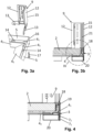
- die Montage eines Eckpfostens an einem Profilrahmen mit dem in
Fig. 2 gezeigten Profilquerschnitt; - Fig. 4
- eine vergrößerte Ansicht der
Fig. 3b gemäß dem Ausschnitt IV derFig. 3b ; und - Fig. 5
- das in
Fig. 1a gezeigte Tablar mit Seitenwänden und Sicherungselementen in einer Explosionsdarstellung. - Das in
Fign. 1a, 1b gezeigte Tablar 1 umfasst eine rechteckige Bodenplatte 2 und einen die Bodenplatte 2 umgebenden, rechteckigen Profilrahmen 3. Der Profilrahmen 3 weist einen innen ringsum umlaufenden (horizontalen) Bodenschenkel 4, auf welchem die Bodenplatte 2 aufliegt und befestigt ist, und einen sich außen an den Bodenschenkel 4 anschließenden, umlaufenden (vertikalen) Außenschenkel 5 auf, welcher rechtwinklig zum Bodenschenkel 4 ausgerichtet ist. Die Bodenplatte 2 kann beispielsweise an dem Bodenschenkel 4 angeschraubt oder angeklebt sein. - Der Außenschenkel 5 weist einen sich oberhalb des Bodenschenkels 4 erstreckenden oberen Schenkelabschnitt 6 und einen sich unterhalb des Bodenschenkels 4 erstreckenden unteren Schenkelabschnitt 7 auf. Der obere Schenkelabschnitt 6 kann, wie in
Fig. 1b gezeigt, auf gleicher Höhe mit der Oberseite der Bodenplatte 2 enden, aber alternativ auch unterhalb oder oberhalb der Oberseite der Bodenplatte 2 enden. Die Bodenplatte 2 und der Außenschenkel 5 sind voneinander horizontal beabstandet, um eine nach oben offene, umlaufende Fuge 8 zum Einsetzen und Befestigen von Aufbauelementen, z.B. von Eckpfosten 9, auszubilden. - Der Profilrahmen 3 kann durch ein einziges Profilteil, das zu einem Rahmen verbunden ist, oder durch mehrere Profilteile mit jeweils gleichen oder unterschiedlichen Profilquerschnitten, die zu einem Rahmen verbunden sind, gebildet sein.
-
Fig. 2 zeigt einen möglichen Profilquerschnitt des Profilrahmens 3 in Form eines abgekanteten Metallblechs. Das Metallblech ist an der Unterkante 10a des unteren Schenkelabschnitts 7 um 180° umgebogen, um den unteren Schenkelabschnitt 7 doppellagig mit einer inneren und einer äußeren Blechlage 71, 72 auszubilden. Ausgehend von seiner einen Längskante, welche die Oberkante des oberen Schenkelabschnitts 6 bildet, erstreckt sich das Metallblech vertikal nach unten, um den vertikalen oberen Schenkelabschnitt 6 und die vertikale innere Blechlage 72 auszubilden, und ist an der Unterkante 10a des unteren Schenkelabschnitts 7 um 180° nach innen umgebogen, um die vertikale innere Blechlage 71 auszubilden. Die beiden Blechlagen 71, 72 liegen parallel aufeinander und können miteinander innenseitig verklebt oder punktverschweißt sein. Von der inneren Blechlage 71 ist der horizontale Bodenschenkel 4 um 90° nach außen umgebogen und dann Z-förmig abgekantet, um einen an den Außenschenkel 5 angrenzenden, höheren horizontalen, äußeren Schenkelabschnitt 41 und einen tieferen horizontalen, inneren Schenkelabschnitt 42 auszubilden. Die Innenkante des inneren Schenkelabschnitts 42, welche die Rahmenöffnung des Profilrahmens 3 definiert, ist somit durch die andere Längskante des Metallprofils gebildet. Der gesamte Profilrahmen 3 kann aus einem einzigen Blechzuschnitt durch Umbiegen gebildet und dann zu einem geschlossenen Rahmen verbunden sein. - Alternativ kann das Metallblech aber auch an der Oberkante 10b des oberen Schenkelabschnitts 6 um 180° umgebogen sein, um den oberen Schenkelabschnitt 6 doppellagig mit einer inneren und einer äußeren Blechlage auszubilden.
- Die Bodenplatte 2 liegt auf dem Bodenschenkel 4 entweder unmittelbar auf dem höheren oder dem tieferen Schenkelabschnitt 41, 42 oder, wie in
Fig. 1b gezeigt, mittels Abstandshalter 11 auf. Über die Höhe der gewählten Abstandshalter 11 kann eine gewünschte, positive oder negative Höhendifferenz zwischen der Oberseite der Bodenplatte 2 und der Oberkante des Außenschenkels 5 eingestellt werden. InFig. 1b liegen die Abstandshalter 11 auf dem inneren Schenkelabschnitt 42 auf. - In den
Fign. 3a, 3b ist die Montage des Eckpfostens 9 an dem Profilrahmen 3 gezeigt, hier lediglich beispielhaft an einem Profilrahmen mit dem inFig. 2 gezeigten Profilquerschnitt. Der Eckpfosten 9 ist ein hochstehender Rechteckwinkel mit zwei Winkelschenkeln 12, die im Fußbereich an ihren einander abgewandten Seiten jeweils durch einen nach unten offenen Haken 13 verlängert sind. Zu beiden Seiten der Rahmenecke weist der Bodenschenkel 4, im gezeigten Ausführungsbeispiel der äußere Schenkelabschnitt 41, jeweils eine Bodenöffnung 14 auf. Der Eckpfosten 4 wird schräg zum Bodenschenkel 4 angesetzt und dabei mit seinen beiden Haken 13 in die beiden Bodenöffnungen 14 eingesetzt. Anschließend wird der Eckpfosten 9 durch Verkippen vertikal aufgerichtet, bis die Ecke 15 des Eckpfostens 9 an der Rahmenecke 16 des Profilrahmens 3 anliegt und die Haken 13 am Bodenschenkel 4 festgeklemmt sind. Abschließend kann der Eckpfosten 9 in dieser vertikalen Position mittels eines Sicherungselements, z.B. einer Schraube 17, gesichert werden. - Wie in dem vergrößerten Ausschnitt der
Fig. 4 gezeigt, ist in die Fuge 8 eine Bodenprofilleiste 18 eingesetzt, deren Profiloberseite die Fuge 8 abdeckt. Die Bodenprofilleiste 18 weist einen z.B. schräg zur Profiloberseite verlaufenden Profilschenkel 19 auf, der in der Fuge 8 an der Bodenplatte 2 klemmend gehalten ist. - Wie in den
Fign. 3b und 4 lediglich schematisch angedeutet, ist an zwei einander gegenüberliegenden Rahmenseiten des Profilrahmens 3 jeweils eine (Schubladen)Ausziehführung 20 im Eckbereich zwischen dem Bodenschenkel 4 und dem unteren Schenkelabschnitt 7, im gezeigten Ausführungsbeispiel zwischen dem tieferen inneren Schenkelabschnitt 42 und dem unteren Schenkelabschnitt 7, angeordnet und am Profilrahmen 3 befestigt. In horizontaler Einbaulage des Tablars 1 sind die Ausziehführungen 20 vom unteren Schenkelabschnitt 7 verdeckt und daher von außen nicht sichtbar. - In
Fig. 5 sind zwischen zwei Eckpfosten 9 jeweils Wandelemente 21, z.B. in Form von Vorder-, Rück- und Seitenwänden, eingesetzt und daran z.B. mittels Befestigungselementen 22 kraft- oder formschlüssig fixiert. Die Wandelemente 21 können auf der Bodenprofilleiste 18 aufliegen. - Statt wie in den
Fign. 1 und5 ringsum durchgehend umlaufend, können der Bodenschenkel 4 und der Außenschenkel 5 auch nur abschnittsweise umlaufend ausgebildet sein.
Claims (12)
- Tablar (1), insbesondere Schubladentablar, mit einer rechteckigen Bodenplatte (2) und mit einem die Bodenplatte (2) umgebenden, rechteckigen Profilrahmen (3), der einen innen zumindest abschnittsweise umlaufenden Bodenschenkel (4) aufweist, auf welchem die Bodenplatte (2) aufliegt und befestigbar ist, sowie mit einem sich außen an den Bodenschenkel (4) anschließenden, zumindest abschnittsweise umlaufenden Außenschenkel (5), welcher einen sich oberhalb des Bodenschenkels (4) erstreckenden, oberen Schenkelabschnitt (6) und einen sich unterhalb des Bodenschenkels (4) erstreckenden, unteren Schenkelabschnitt (7) aufweist und vorzugsweise rechtwinklig zum Bodenschenkel (4) ausgerichtet ist, wobei zwischen dem oberen Schenkelabschnitt (6) und der Bodenplatte (2) eine nach oben offene, umlaufende Fuge (8) zum Befestigen, insbesondere Einstecken oder Führen, von Aufbauelementen (9, 18) vorhanden ist, wobei der Profilrahmen (3) durch ein einziges Profilteil, das zu einem Rahmen verbunden ist, oder durch mehrere Profilteile mit jeweils gleichen oder unterschiedlichen Profilquerschnitten, die zu einem Rahmen verbunden sind, gebildet ist, dadurch gekennzeichnet,
dass das Profilteil oder die mehreren Profilteile jeweils durch ein abgekantetes Metallblech gebildet sind, das an der Unterkante (10a) des unteren Schenkelabschnitts (7) um ca. 180° umgebogen ist, um den unteren Schenkelabschnitt (7) doppellagig mit einer inneren und einer äußeren Blechlage (71, 72) auszubilden, oder das an der Oberkante (10b) des oberen Schenkelabschnitts (6) um ca. 180° umgebogen ist, um den oberen Schenkelabschnitt (6) doppellagig mit einer inneren und einer äußeren Blechlage auszubilden. - Tablar nach Anspruch 1, dadurch gekennzeichnet, dass die beiden Blechlagen (71, 72) des unteren bzw. oberen Schenkelabschnitts (7; 6) aneinander befestigt sind, insbesondere miteinander verklebt oder verschweißt sind.
- Tablar nach Anspruch 1 oder 2, dadurch gekennzeichnet, dass der Bodenschenkel (4), vorzugsweise um ca. 90°, von der inneren Blechlage (71) des unteren bzw. oberen Schenkelabschnitts (7; 6) umgebogen ist.
- Tablar nach einem der vorhergehenden Ansprüche, dadurch gekennzeichnet, dass der Bodenschenkel (4) Z-förmig abgekantet ist und einen sich an den Außenschenkel (5) anschließenden, höheren äußeren Schenkelabschnitt (41) und einen tieferen inneren Schenkelabschnitt (42) aufweist und dass die Bodenplatte (2) auf dem höheren äußeren Schenkelabschnitt (41) oder dem tieferen inneren Schenkelabschnitt (42) aufliegt.
- Tablar nach einem der vorhergehenden Ansprüche, dadurch gekennzeichnet, dass die Bodenplatte (2) unmittelbar oder mittels mindestens eines Abstandshalters (11) auf dem Bodenschenkel (4) aufliegt.
- Tablar nach einem der vorhergehenden Ansprüche, dadurch gekennzeichnet, dass in den Eckbereichen des Profilrahmens (3) Eckpfosten (9) in die Fuge (8) eingesetzt und am Bodenschenkel (4) befestigt, insbesondere festgeklemmt oder festgeschraubt, sind.
- Tablar nach Anspruch 6, dadurch gekennzeichnet, dass ein Wandelement (21) zwischen zwei Eckpfosten (9) eingesetzt und daran mittels eines Befestigungselements (22) kraft- oder formschlüssig fixiert ist.
- Tablar nach einem der vorhergehenden Ansprüche, dadurch gekennzeichnet, dass in die Fuge (8) eine Bodenprofilleiste (18) eingesetzt und darin festgeklemmt ist, deren Profiloberseite die Fuge (8) abdeckt.
- Tablar nach einem der vorhergehenden Ansprüche, dadurch gekennzeichnet, dass der Profilrahmen (3) einen ringsum durchgehend umlaufenden Bodenschenkel (4) aufweist.
- Tablar nach einem der vorhergehenden Ansprüche, dadurch gekennzeichnet, dass der Profilrahmen (3) einen ringsum durchgehend umlaufenden Außenschenkel (5) aufweist.
- Tablar nach einem der vorhergehenden Ansprüche, dadurch gekennzeichnet, dass an zwei einander gegenüberliegenden Rahmenseiten des Profilrahmens (3) jeweils eine Ausziehführung (20) im Eckbereich zwischen dem Bodenschenkel (4) und dem unteren Schenkelabschnitt (7), insbesondere im Eckbereich zwischen dem tieferen inneren Schenkelabschnitt (42) und dem unteren Schenkelabschnitt (7), angeordnet und am Profilrahmen (3) befestigt ist.
- Tablar nach einem der vorhergehenden Ansprüche, dadurch gekennzeichnet, dass die innere und die äußere Blechlage (71, 72) des unteren Schenkelabschnitts (7) oder die innere und die äußere Blechlage des oberen Schenkelabschnitts (6) parallel aufeinanderliegen,
Applications Claiming Priority (1)
| Application Number | Priority Date | Filing Date | Title |
|---|---|---|---|
| DE202021102831.9U DE202021102831U1 (de) | 2021-05-25 | 2021-05-25 | Tablar mit steckbaren Aufbauten |
Publications (2)
| Publication Number | Publication Date |
|---|---|
| EP4094626A1 EP4094626A1 (de) | 2022-11-30 |
| EP4094626B1 true EP4094626B1 (de) | 2025-04-30 |
Family
ID=76543066
Family Applications (1)
| Application Number | Title | Priority Date | Filing Date |
|---|---|---|---|
| EP22163976.8A Active EP4094626B1 (de) | 2021-05-25 | 2022-03-24 | Tablar mit steckbaren aufbauten |
Country Status (4)
| Country | Link |
|---|---|
| EP (1) | EP4094626B1 (de) |
| CN (1) | CN115384899B (de) |
| DE (1) | DE202021102831U1 (de) |
| PL (1) | PL4094626T3 (de) |
Family Cites Families (7)
| Publication number | Priority date | Publication date | Assignee | Title |
|---|---|---|---|---|
| DE1102545B (de) * | 1957-12-27 | 1961-03-16 | Aweso Werke A Weber U Sohn | Stellvorrichtung fuer Aussenglasscheiben und Glastrennwaende von Ladentischen und Ausstelltablaren |
| CH590033A5 (en) * | 1975-02-21 | 1977-07-29 | Fehlbaum & Co | Partitioned sales display cases - has hollow sections with grooves to support glass walls |
| ZA827453B (en) * | 1981-10-30 | 1983-08-31 | Fehlbaum & Co | Shelf with a supporting frame and with removable limiting wall elements |
| DE202009003826U1 (de) * | 2009-03-20 | 2010-08-12 | Paul Hettich Gmbh & Co. Kg | Auszugsführung |
| CN103148335A (zh) * | 2011-12-07 | 2013-06-12 | 中国国际海运集装箱(集团)股份有限公司 | 中空型材以及使用该中空型材的托盘箱 |
| DE102016015780A1 (de) * | 2016-12-08 | 2018-06-14 | HAROMAC Werkzeugfabrik GmbH & Co. KG | Auszug für eine Werkbank |
| DE202019106557U1 (de) * | 2019-11-26 | 2020-01-07 | Anton Schneider Gmbh & Co Kg | Tablar mit steckbaren Aufbauten |
-
2021
- 2021-05-25 DE DE202021102831.9U patent/DE202021102831U1/de active Active
-
2022
- 2022-03-24 EP EP22163976.8A patent/EP4094626B1/de active Active
- 2022-03-24 PL PL22163976.8T patent/PL4094626T3/pl unknown
- 2022-05-25 CN CN202210577333.5A patent/CN115384899B/zh active Active
Also Published As
| Publication number | Publication date |
|---|---|
| PL4094626T3 (pl) | 2025-09-01 |
| CN115384899B (zh) | 2025-06-24 |
| CN115384899A (zh) | 2022-11-25 |
| DE202021102831U1 (de) | 2021-06-08 |
| EP4094626A1 (de) | 2022-11-30 |
Similar Documents
| Publication | Publication Date | Title |
|---|---|---|
| WO2012028489A1 (de) | Möbelauszugsteil | |
| DE20304079U1 (de) | Schublade | |
| EP3827708B1 (de) | Tablar mit steckbaren aufbauten | |
| EP3545793A1 (de) | Aus vertikal und horizontal verlaufenden profilteilen gebildetes möbel sowie möbel mit zumindest zwei seitenwänden | |
| DE8702096U1 (de) | Konstruktiver Aufbau für Haushalts-Backöfen | |
| WO2022033935A1 (de) | Begrünbares wandelement | |
| DE3441500C2 (de) | Regalboden aus Schichtwerkstoff, insbesondere Metallblech | |
| DE4342366A1 (de) | Container | |
| EP4094626A1 (de) | Tablar mit steckbaren aufbauten | |
| DE19837184C2 (de) | Gestell für einen 19"-Verteilerschrank | |
| AT401854B (de) | Schublade | |
| EP4173476B1 (de) | Hochbeet mit seitenwänden und querstreben | |
| DE202023105195U1 (de) | Hochbeetgestell und Kit-of-Parts für ein Hochbeetgestell | |
| DE102005008645A1 (de) | Eckverbinder zum Verbinden zweier Profilleisten | |
| EP1037346A1 (de) | Rahmengestell für einen Schrank | |
| DE202019101889U1 (de) | Untergestell für ein Gargerät | |
| DE9211558U1 (de) | Pflanzenkübel | |
| DE8716243U1 (de) | Bausatz für ein Bett | |
| DE8433163U1 (de) | Schwimmbadabdeckung | |
| DE29622444U1 (de) | Zaun | |
| DE3925215A1 (de) | Rolladen-verschluss fuer moebel oder dgl. | |
| DE9415504U1 (de) | Regalsystem | |
| DE29916580U1 (de) | Bausatz für Metallbox | |
| AT511450A4 (de) | Gewächshaus mit Hochbeet | |
| DE202005015681U1 (de) | Transportcontainer |
Legal Events
| Date | Code | Title | Description |
|---|---|---|---|
| PUAI | Public reference made under article 153(3) epc to a published international application that has entered the european phase |
Free format text: ORIGINAL CODE: 0009012 |
|
| STAA | Information on the status of an ep patent application or granted ep patent |
Free format text: STATUS: THE APPLICATION HAS BEEN PUBLISHED |
|
| STAA | Information on the status of an ep patent application or granted ep patent |
Free format text: STATUS: REQUEST FOR EXAMINATION WAS MADE |
|
| AK | Designated contracting states |
Kind code of ref document: A1 Designated state(s): AL AT BE BG CH CY CZ DE DK EE ES FI FR GB GR HR HU IE IS IT LI LT LU LV MC MK MT NL NO PL PT RO RS SE SI SK SM TR |
|
| 17P | Request for examination filed |
Effective date: 20221104 |
|
| RBV | Designated contracting states (corrected) |
Designated state(s): AL AT BE BG CH CY CZ DE DK EE ES FI FR GB GR HR HU IE IS IT LI LT LU LV MC MK MT NL NO PL PT RO RS SE SI SK SM TR |
|
| P01 | Opt-out of the competence of the unified patent court (upc) registered |
Effective date: 20230630 |
|
| STAA | Information on the status of an ep patent application or granted ep patent |
Free format text: STATUS: EXAMINATION IS IN PROGRESS |
|
| 17Q | First examination report despatched |
Effective date: 20231121 |
|
| GRAP | Despatch of communication of intention to grant a patent |
Free format text: ORIGINAL CODE: EPIDOSNIGR1 |
|
| STAA | Information on the status of an ep patent application or granted ep patent |
Free format text: STATUS: GRANT OF PATENT IS INTENDED |
|
| INTG | Intention to grant announced |
Effective date: 20241111 |
|
| GRAS | Grant fee paid |
Free format text: ORIGINAL CODE: EPIDOSNIGR3 |
|
| GRAA | (expected) grant |
Free format text: ORIGINAL CODE: 0009210 |
|
| STAA | Information on the status of an ep patent application or granted ep patent |
Free format text: STATUS: THE PATENT HAS BEEN GRANTED |
|
| AK | Designated contracting states |
Kind code of ref document: B1 Designated state(s): AL AT BE BG CH CY CZ DE DK EE ES FI FR GB GR HR HU IE IS IT LI LT LU LV MC MK MT NL NO PL PT RO RS SE SI SK SM TR |
|
| REG | Reference to a national code |
Ref country code: CH Ref legal event code: EP Ref country code: GB Ref legal event code: FG4D Free format text: NOT ENGLISH |
|
| REG | Reference to a national code |
Ref country code: IE Ref legal event code: FG4D Free format text: LANGUAGE OF EP DOCUMENT: GERMAN |
|
| REG | Reference to a national code |
Ref country code: DE Ref legal event code: R096 Ref document number: 502022003724 Country of ref document: DE |
|
| REG | Reference to a national code |
Ref country code: NL Ref legal event code: MP Effective date: 20250430 |
|
| PG25 | Lapsed in a contracting state [announced via postgrant information from national office to epo] |
Ref country code: FI Free format text: LAPSE BECAUSE OF FAILURE TO SUBMIT A TRANSLATION OF THE DESCRIPTION OR TO PAY THE FEE WITHIN THE PRESCRIBED TIME-LIMIT Effective date: 20250430 Ref country code: PT Free format text: LAPSE BECAUSE OF FAILURE TO SUBMIT A TRANSLATION OF THE DESCRIPTION OR TO PAY THE FEE WITHIN THE PRESCRIBED TIME-LIMIT Effective date: 20250901 Ref country code: ES Free format text: LAPSE BECAUSE OF FAILURE TO SUBMIT A TRANSLATION OF THE DESCRIPTION OR TO PAY THE FEE WITHIN THE PRESCRIBED TIME-LIMIT Effective date: 20250430 |
|
| REG | Reference to a national code |
Ref country code: LT Ref legal event code: MG9D |
|
| PG25 | Lapsed in a contracting state [announced via postgrant information from national office to epo] |
Ref country code: GR Free format text: LAPSE BECAUSE OF FAILURE TO SUBMIT A TRANSLATION OF THE DESCRIPTION OR TO PAY THE FEE WITHIN THE PRESCRIBED TIME-LIMIT Effective date: 20250731 Ref country code: NO Free format text: LAPSE BECAUSE OF FAILURE TO SUBMIT A TRANSLATION OF THE DESCRIPTION OR TO PAY THE FEE WITHIN THE PRESCRIBED TIME-LIMIT Effective date: 20250730 |
|
| PG25 | Lapsed in a contracting state [announced via postgrant information from national office to epo] |
Ref country code: NL Free format text: LAPSE BECAUSE OF FAILURE TO SUBMIT A TRANSLATION OF THE DESCRIPTION OR TO PAY THE FEE WITHIN THE PRESCRIBED TIME-LIMIT Effective date: 20250430 |
|
| PG25 | Lapsed in a contracting state [announced via postgrant information from national office to epo] |
Ref country code: BG Free format text: LAPSE BECAUSE OF FAILURE TO SUBMIT A TRANSLATION OF THE DESCRIPTION OR TO PAY THE FEE WITHIN THE PRESCRIBED TIME-LIMIT Effective date: 20250430 |
|
| PG25 | Lapsed in a contracting state [announced via postgrant information from national office to epo] |
Ref country code: HR Free format text: LAPSE BECAUSE OF FAILURE TO SUBMIT A TRANSLATION OF THE DESCRIPTION OR TO PAY THE FEE WITHIN THE PRESCRIBED TIME-LIMIT Effective date: 20250430 |
|
| PG25 | Lapsed in a contracting state [announced via postgrant information from national office to epo] |
Ref country code: RS Free format text: LAPSE BECAUSE OF FAILURE TO SUBMIT A TRANSLATION OF THE DESCRIPTION OR TO PAY THE FEE WITHIN THE PRESCRIBED TIME-LIMIT Effective date: 20250731 |
|
| PG25 | Lapsed in a contracting state [announced via postgrant information from national office to epo] |
Ref country code: IS Free format text: LAPSE BECAUSE OF FAILURE TO SUBMIT A TRANSLATION OF THE DESCRIPTION OR TO PAY THE FEE WITHIN THE PRESCRIBED TIME-LIMIT Effective date: 20250830 |
|
| PG25 | Lapsed in a contracting state [announced via postgrant information from national office to epo] |
Ref country code: LV Free format text: LAPSE BECAUSE OF FAILURE TO SUBMIT A TRANSLATION OF THE DESCRIPTION OR TO PAY THE FEE WITHIN THE PRESCRIBED TIME-LIMIT Effective date: 20250430 |
|
| PG25 | Lapsed in a contracting state [announced via postgrant information from national office to epo] |
Ref country code: SM Free format text: LAPSE BECAUSE OF FAILURE TO SUBMIT A TRANSLATION OF THE DESCRIPTION OR TO PAY THE FEE WITHIN THE PRESCRIBED TIME-LIMIT Effective date: 20250430 Ref country code: DK Free format text: LAPSE BECAUSE OF FAILURE TO SUBMIT A TRANSLATION OF THE DESCRIPTION OR TO PAY THE FEE WITHIN THE PRESCRIBED TIME-LIMIT Effective date: 20250430 |
|
| PG25 | Lapsed in a contracting state [announced via postgrant information from national office to epo] |
Ref country code: CZ Free format text: LAPSE BECAUSE OF FAILURE TO SUBMIT A TRANSLATION OF THE DESCRIPTION OR TO PAY THE FEE WITHIN THE PRESCRIBED TIME-LIMIT Effective date: 20250430 |
|
| PG25 | Lapsed in a contracting state [announced via postgrant information from national office to epo] |
Ref country code: EE Free format text: LAPSE BECAUSE OF FAILURE TO SUBMIT A TRANSLATION OF THE DESCRIPTION OR TO PAY THE FEE WITHIN THE PRESCRIBED TIME-LIMIT Effective date: 20250430 |
|
| PG25 | Lapsed in a contracting state [announced via postgrant information from national office to epo] |
Ref country code: SK Free format text: LAPSE BECAUSE OF FAILURE TO SUBMIT A TRANSLATION OF THE DESCRIPTION OR TO PAY THE FEE WITHIN THE PRESCRIBED TIME-LIMIT Effective date: 20250430 |
|
| REG | Reference to a national code |
Ref country code: DE Ref legal event code: R097 Ref document number: 502022003724 Country of ref document: DE |
|
| PLBE | No opposition filed within time limit |
Free format text: ORIGINAL CODE: 0009261 |
|
| STAA | Information on the status of an ep patent application or granted ep patent |
Free format text: STATUS: NO OPPOSITION FILED WITHIN TIME LIMIT |
|
| REG | Reference to a national code |
Ref country code: CH Ref legal event code: L10 Free format text: ST27 STATUS EVENT CODE: U-0-0-L10-L00 (AS PROVIDED BY THE NATIONAL OFFICE) Effective date: 20260311 |
|
| 26N | No opposition filed |
Effective date: 20260202 |
|
| PGFP | Annual fee paid to national office [announced via postgrant information from national office to epo] |
Ref country code: DE Payment date: 20260327 Year of fee payment: 5 |
|
| PGFP | Annual fee paid to national office [announced via postgrant information from national office to epo] |
Ref country code: AT Payment date: 20260301 Year of fee payment: 5 |
|
| PGFP | Annual fee paid to national office [announced via postgrant information from national office to epo] |
Ref country code: PL Payment date: 20260224 Year of fee payment: 5 |