EP4093640B1 - Verfahren zur ermittlung eines installationsverbotsbereiches eines sensors - Google Patents
Verfahren zur ermittlung eines installationsverbotsbereiches eines sensors Download PDFInfo
- Publication number
- EP4093640B1 EP4093640B1 EP21700729.3A EP21700729A EP4093640B1 EP 4093640 B1 EP4093640 B1 EP 4093640B1 EP 21700729 A EP21700729 A EP 21700729A EP 4093640 B1 EP4093640 B1 EP 4093640B1
- Authority
- EP
- European Patent Office
- Prior art keywords
- seat
- sensor
- windscreen
- driver
- distance
- Prior art date
- Legal status (The legal status is an assumption and is not a legal conclusion. Google has not performed a legal analysis and makes no representation as to the accuracy of the status listed.)
- Active
Links
Images

Classifications
-
- B—PERFORMING OPERATIONS; TRANSPORTING
- B60—VEHICLES IN GENERAL
- B60R—VEHICLES, VEHICLE FITTINGS, OR VEHICLE PARTS, NOT OTHERWISE PROVIDED FOR
- B60R11/00—Arrangements for holding or mounting articles, not otherwise provided for
- B60R11/04—Mounting of cameras operative during drive; Arrangement of controls thereof relative to the vehicle
-
- B—PERFORMING OPERATIONS; TRANSPORTING
- B60—VEHICLES IN GENERAL
- B60R—VEHICLES, VEHICLE FITTINGS, OR VEHICLE PARTS, NOT OTHERWISE PROVIDED FOR
- B60R11/00—Arrangements for holding or mounting articles, not otherwise provided for
- B60R2011/0001—Arrangements for holding or mounting articles, not otherwise provided for characterised by position
- B60R2011/0003—Arrangements for holding or mounting articles, not otherwise provided for characterised by position inside the vehicle
- B60R2011/0026—Windows, e.g. windscreen
-
- B—PERFORMING OPERATIONS; TRANSPORTING
- B60—VEHICLES IN GENERAL
- B60R—VEHICLES, VEHICLE FITTINGS, OR VEHICLE PARTS, NOT OTHERWISE PROVIDED FOR
- B60R2300/00—Details of viewing arrangements using cameras and displays, specially adapted for use in a vehicle
- B60R2300/40—Details of viewing arrangements using cameras and displays, specially adapted for use in a vehicle characterised by the details of the power supply or the coupling to vehicle components
- B60R2300/402—Image calibration
Definitions
- the present invention relates to a method for determining a prohibited installation area of a sensor, in particular a photo or video camera, of a windshield of a commercial vehicle in order to prevent the sensor from obstructing the driver's view.
- a sensor in particular a photo or video camera
- the document ENGINEER-BUREAU OF THE CITY OF ZURICH ET AL: "City of Zurich", March 24, 2011 (2011-03-24), pages 1 - 4, XP055777635 , [accessed on the Internet on February 2021, 2018] discloses a method according to the state of the art.
- sensors In order to improve the driving safety of commercial vehicles, retrofitted sensors, in particular photo or video cameras, have been used for some time, which are attached to a windshield of the commercial vehicle in order to provide the driver with additional information about the area in front of the vehicle.
- sensors or photo or video cameras are night vision devices, thermal imaging cameras, infrared sensors or the like, which make it possible to detect people, animals or objects at an early stage, even in poor visibility, for example caused by fog, rain or darkness.
- the object of the present invention is to provide a method for determining a prohibited installation area of a sensor, in particular a photo or video camera, of a windshield of a commercial vehicle in order to prevent the sensor from obstructing the driver's view, which requires little time, space and is required to determine Work equipment is also possible within workshops with limited space available.
- This object is achieved by a method for determining a prohibited installation area of a sensor, in particular a photo or video camera, of a windshield of a commercial vehicle in order to prevent a vehicle driver from being obstructed by the sensor with the method steps specified in claim 1.
- the method according to the invention makes it possible to determine the area on the windshield of the commercial vehicle in which the sensor may not be placed for reasons of visibility in a simple manner and in particular without requiring a large measuring area.
- a large number of value pairs of the coordinates calculated using the calculation algorithm are stored in advance in a table so that they can be read, at least the values Hs, Ws, H L and V L being readable in the table and where In step III the corner point is read from the table.
- the installation prohibition area is marked on the windshield after the corner point has been determined.
- top, bottom, left, right, front, rear, etc. refer exclusively to the exemplary representation and position of the commercial vehicle, the sensor, the vehicle driver's seat and the like selected in the respective figures. These terms are not to be understood as restrictive, i.e. these relationships can change due to different working positions or the mirror-symmetrical design or the like.
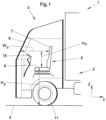
- the Fig. 1 In a Cartesian coordinate system, the Fig. 1 ) and the Y-axis runs perpendicular to the Y-axis and to the Z-axis against the direction of travel of the commercial vehicle 1 when traveling straight ahead.
- the reference number 1 denotes a commercial vehicle as a whole.
- the commercial vehicle here has, for example, a tractor 3 and a trailer 2 coupled to it.
- a vehicle driver's seat 5 with a seat surface 6 is installed in a conventional design, which is attached centrally behind a steering wheel 15 when viewed in the x direction.
- a predetermined area of a windshield 8 must be free of devices that obstruct vision, such as the above-mentioned sensor.
- a process step I as in Figure 1 is shown schematically, the distance Hs between a seat surface 6 of the vehicle driver's seat 5 and the surface of a floor 4 on which the wheels 11 of the commercial vehicle 1 stand up, measured.
- a process step II as also in Figure 1 is shown schematically, the distance Ws between a backrest 6 of the vehicle driver's seat 5 and the inner surface of the windshield 8 is measured at a predetermined height H P above the seat surface 6 of the vehicle driver's seat 5 parallel to the surface of the floor 4.
- the two process steps I and II can be carried out in the specified order or vice versa.
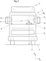
- a method step III the coordinates H L , V L of a corner point P are then determined, as exemplified in Figure 2 is shown, the rectangular installation prohibition area 9 on the windshield 8 based on the distance values measured in I and II by a calculation algorithm.
- the coordinate H L corresponds to the distance of the corner point P from an imaginary center line Ms of the vehicle driver's seat 5 in the direction of a passenger-side edge 13 of the windshield 8.
- the coordinate V L corresponds to the distance of the corner point P from the surface of the ground 4.
- the installation prohibition area 9 on the windshield 8 extends from the corner point P vertically in the direction z upwards to the upper edge 14 and horizontally in the direction x to the driver-side edge 12 of the windshield 8.
- the installation prohibition area 9 on the windshield 8 extends from the corner point P horizontally against the direction x to the driver's side edge 12 of the windshield 8.
- a predetermined eye point at a predetermined height H P above the seat surface 6 of the vehicle driver's seat 5 parallel to the surface of the floor 4 is taken into account in accordance with the StVZO (Road Traffic Licensing Regulations) valid in Germany .
- This height is H P according to the current StVZO 700mm.
- a large number of value pairs of the coordinates H L , V L calculated with the calculation algorithm are stored in advance in a table so that they can be read, at least the values Hs, Ws, H L and V L being readable in the table and in step III the corner point P is read from the table.
- Such a table can be available as a printout or stored in a data processing device and can be accessed via a screen of the data processing device.
- a preferably mobile data processing device for example a notebook, on which a program containing the calculation algorithm is installed.
- the installation prohibition area 9 is marked on the windshield 8 in an optional method step IV, so that the installation of the sensor, in particular in the form of a photo or video camera, can be carried out at a later point in time without further measurement in an area 10 of the windshield 8 that can be used for the installation .
Landscapes
- Engineering & Computer Science (AREA)
- Mechanical Engineering (AREA)
- Length Measuring Devices By Optical Means (AREA)
- Fittings On The Vehicle Exterior For Carrying Loads, And Devices For Holding Or Mounting Articles (AREA)
- Measurement Of Optical Distance (AREA)
Description
- Die vorliegende Erfindung betrifft ein Verfahren zur Ermittlung eines Installationsverbotsbereiches eines Sensors, insbesondere einer Foto- oder Videokamera, einer Windschutzscheibe eines Nutzfahrzeugs zur Verhinderung einer Sichtbehinderung eines Fahrzeugführers durch den Sensor. Das Dokument INGENIEUR-BUREAU DER STADT ZÜRICH ET AL: "Stadt Zürich", 24 März 2011 (2011-03-24), Seiten 1 - 4, XP055777635, [abgerufen im Internet am 2021.02.18] offenbart ein Verfahren nach dem Stand der Technik.
- Zur Verbesserung der Fahrsicherheit von Nutzfahrzeugen werden seit einiger Zeit nachträglich eingebaute Sensoren, insbesondere auch Foto- oder Videokameras, genutzt, die an einer Windschutzscheibe des Nutzfahrzeugs angebracht werden, um so dem Fahrzeugführer zusätzliche Informationen über den Bereich vor dem Fahrzeug zur Verfüfung zu stellen. Beispiele solcher Sensoren oder Foto- oder Videokameras sind Nachtsichtgeräte, Wärmebildkameras, Infrarotsensoren oder dergleichen, mit denen ermöglicht ist, auch bei schlechter Sicht, beispielsweise verursacht durch Nebel, Regen oder Dunkelheit, Personen, Tiere oder Gegenstände frühzeitig erkennen zu können.
- Um eine Sichtbehinderung eines Fahrzeugführers durch einen solchen Sensor zu verhindern, ist es bekannt, mittels auf einer Fahrbahn gezeichneter Sichtfelder / Kreise das Sichtfeld eines Fahrzeugführers in der Fahrerkabine des Nutzfahrzeugs zu überprüfen. Dazu muss gemäß der deutschen Straßenverkehrs-Zulassungs-Ordnung unter anderem ein Halbkreis (sogenannter Sichthalbkreis) um einen geloteten Punkt unterhalb des Augenpunktes des Fahrzeugführers mit einem Radius von 12m auf der Fahrbahn aufgezeichnet werden.
- Bei Installationen solcher Sensoren, insbesondere Foto- oder Videokameras, in der Fahrerkabine des Nutzfahrzeugs ist in zahlreichen Werkstätten der dazu notwendige Platz nicht gegeben. Auch ist der insbesondere zeitliche Aufwand für die Erstellung solcher Fahrbahnmarkierungen sehr groß.
- Aufgabe der vorliegenden Erfindung ist es, ein Verfahren zur Ermittlung eines Installationsverbotsbereiches eines Sensors, insbesondere einer Foto- oder Videokamera, einer Windschutzscheibe eines Nutzfahrzeugs zur Verhinderung einer Sichtbehinderung eines Fahrzeugführers durch den Sensor bereit zu stellen, das mit wenig Zeitaufwand, Platzbedarf und zur Ermittlung benötigter Arbeitsmitteln auch innerhalb von Werkstätten mit geringem zur Verfügung stehendem Raum möglich ist.
- Diese Aufgabe wird durch ein Verfahren zur Ermittlung eines Installationsverbotsbereiches eines Sensors, insbesondere einer Foto- oder Videokamera, einer Windschutzscheibe eines Nutzfahrzeugs zur Verhinderung einer Sichtbehinderung eines Fahrzeugführers durch den Sensor mit den in Anspruch 1 angegebenen Verfahrensschritte gelöst.
- Das erfindungsgemäße Verfahren zeichnet sich durch die folgenden Verfahrensschritte aus:
- I Messen des Abstandes zwischen einer Sitzfläche eines Fahrzeugführerersitzes (und der Oberfläche eines Bodens, auf dem die Räder des Nutzfahrzeugs aufstehen;
- II Messen eines Abstandes zwischen einer Rückenlehne eines Fahrzeugführerersitzes und der Innenfläche der Windschutzscheibe in einer vorbestimmten Höhe oberhalb der Sitzfläche des Fahrzeugführerersitzes parallel zur Oberfläche des Bodens;
- III Ermittlung von Koordinaten HL, VL eines Eckpunktes eines rechteckigen Installationsverbotsbereiches auf der Windschutzscheibe auf Basis der in I und II gemessenen Abstandswerte durch einen Rechenalgorithmus, wobei
- HL dem Abstand des Eckpunktes von einer gedachten Mittellinie des Fahrzeugführerersitzes in Richtung eines beifahrerseitigen Randes der Windschutzscheibe und
- VL dem Abstand des Eckpunktes von der Oberfläche des Bodens entspricht,
- Mit dem erfindungsgemäßen Verfahren ist es in einfacher und insbesondere ohne Benötigung einer großen Meßfläche ermöglicht, den Bereich auf der Windschutzscheibe des Nutzfahrzeugs zu ermitteln, in dem der Sensor aus Sichtgründen nicht platziert werden darf.
- Bei der Ermittlung eines nutzbaren Anbringungsbereiches für den Sensor ist es lediglich notwendig, mithilfe einfacher Abstandsmeßinstrumente den Abstand der Sitzfläche des Fahrersitzes vom Boden, auf dem die Räder des Nutzfahrzeugs aufstehen sowie den Abstand der Rückenlehne des Fahrersitzes zur Windschutzscheibe in einer vorbestimmten Höhe relativ zur Sitzfläche des Fahrersitzes auszumessen. Daraus lässt sich mithilfe des Rechenalgorithmus in einerfacher Weise ein Eckpunkt eines rechteckigen Installationsverbotsbereiches auf der Windschutzscheibe ermitteln, auf der Windschutzscheibe markieren und so in einfacher Weise ein Installationsort auf der Widschutzscheibe auswählen, der außerhalb des Verbotsbereiches liegt.
- Vorteilhafte Ausführungsvarianten der Erfindung sind Gegenstand der Unteransprüche.
- Gemäß einer vorteilhaften Ausführungsvariante der Erfindung wird vor der Bestimmung des nutzbaren Anbringungsbereiches eine Vielzahl von mit dem Rechenalgorithmus berechneten Wertepaaren der Koordinaten vorab in einer Tabelle ablesbar abgespeichert, wobei in der Tabelle zumindest die Werte Hs, Ws, HL und VL ablesbar sind und wobei in Schritt III der Eckpunkt aus der Tabelle abgelesen wird.
- Mit einer solchen Tabelle lässt sich in einfacher Weise aus den gemessenen Daten der Eckpunkt des rechteckigen Installationsverbotsbereiches auf der Windschutzscheibe ablesen.
- Gemäß einer vorteilhaften Weiterbildung wird nach Bestimmung des Eckpunktes der Installationsverbotsbereich auf der Windschutzscheibe markiert.
- Dadurch ist ermöglicht, die Installation des Sensors, insbesondere in Gestalt einer Videokamera zu einem späteren Zeitpunkt oder von einer anderen Person durchführen zu lassen als der Person, die die Bestimmung des Installationsverbotsbereiches vorgenommen hat.
- Nachfolgend werden Ausführungsbeispiele der Erfindung anhand der beiliegenden Zeichnungen näher erläutert. Es zeigen:
- Figur 1
- eine schematische Seitenansicht eines Nutzfahrzeugs mit Zugmaschine und teilweise dargestelltem Anhänger,
- Figur 2
- eine schematische Frontansicht auf das Nutzfahrzeug, und
- Figur 3
- eine schematische Frontansicht auf die Windschutzscheibe des Nutzfahrzeugs mit markiertem Installationsverbotsbereich.
- In der nachfolgenden Figurenbeschreibung beziehen sich Begriffe wie oben, unten, links, rechts, vorne, hinten usw. ausschließlich auf die in den jeweiligen Figuren gewählte beispielhafte Darstellung und Position des Nutzfahrzeugs, des Sensors, des Fahrzeugführerersitzes und dergleichen. Diese Begriffe sind nicht einschränkend zu verstehen, d.h., durch verschiedene Arbeitsstellungen oder die spiegelsymmetrische Auslegung oder dergleichen können sich diese Bezüge ändern.
- In einem kartesischen Koordinatensystem liegt die X-Achse parallel zu einer gedachten Verbindungslinie zwische Fahrzeugführertür und Beifahrertür, die Z-Achse verläuft senkrecht zur Oberfläche des Bodens, auf dem das Nutzfahrzeug 1 mit seinen Rädern 11 aufsteht (siehe
Fig. 1 ) und die Y-Achse verläuft senkrecht zur Y-Achse und zur Z-Achse entgegen der Fahrtrichtung des Nutzfahrzeugs 1 bei Vorwärts-Geradeausfahrt. - In
Fig. 1 ist mit dem Bezugszeichen 1 insgesamt ein Nutzfahrzeug bezeichnet. Das Nutzfahrzeug weist hier beispielhaft eine Zugmaschine 3 und einen an diese angekoppelten Anhänger 2 auf. In einer Fahrerkabine des Nutzfahrzeugs 1 ist in üblicher Bauweise ein Fahrzeugführerersitz 5 mit einer Sitzfläche 6 eingebaut, der in x-Richtung betrachtet mittig hinter einem Lenkrad 15 befestigt ist. - Um eine Sichtbehinderung eines auf dem Fahrzeugführerersitz 5 sitzenden Fahrzeugführers durch einen (nicht dargestellten) Sensor, insbesondere in Gestalt einer einer Foto- oder Videokamera zu verhindern, muß ein vorbestimmter Bereich einer Windschutzscheibe 8 frei von sichtbehindernden Geräten wie dem oben genannten Sensor sein.
- Zur Bestimmung dieses Installationsverbotsbereiches 9 der Windschutzscheibe 8, wie beispielhaft in
Figur 3 dargestellt ist, werden erfindungsgemäß die folgenden Verfahrensschritte vorgenommen:
In einem Verfahrensschritt I wird, wie inFigur 1 schematisch dargestellt ist, der Abstand Hs zwischen einer Sitzfläche 6 des Fahrzeugführerersitzes 5 und der Oberfläche eines Bodens 4, auf dem die Räder 11 des Nutzfahrzeugs 1 aufstehen, gemessen. - In einem Verfahrensschritt II wird, wie ebenfalls in
Figur 1 schematisch dargestellt ist, der Abstand Ws zwischen einer Rückenlehne 6 des Fahrzeugführerersitzes 5 und der Innenfläche der Windschutzscheibe 8 in einer vorbestimmten Höhe HP oberhalb der Sitzfläche 6 des Fahrzeugführer-ersitzes 5 parallel zur Oberfläche des Bodens 4 gemessen. - Die beiden Verfahrensschritte I und II können dabei in der angegbene Reihenfolge oder auch umgekehrt durchgeführt werden.
- In einem Verfahrensschritt III erfolgt dann die Ermittlung von Koordinaten HL, VL eines Eckpunktes P, wie beispielhaft in
Figur 2 dargestellt ist, des rechteckigen Installationsverbotsbereiches 9 auf der Windschutzscheibe 8 auf Basis der in I und II gemessenen Abstandswerte durch einen Rechenalgorithmus. - Die Koordinate HL entspricht dabei dem Abstand des Eckpunktes P von einer gedachten Mittellinie Ms des Fahrzeugführerersitzes 5 in Richtung eines beifahrerseitigen Randes 13 der Windschutzscheibe 8.
- Die Koordinate VL entspricht dem Abstand des Eckpunktes P von der Oberfläche des Bodens 4.
- Der Installationsverbotsbereich 9 auf der Windschutzscheibe 8 erstreckt sich von dem Eckpunkt P vertikal in Richtung z nach oben bis zum oberen Rand 14 und horizontal in Richtung x bis zum fahrerseitigen Rand 12 der Windschutzscheibe 8.
- Befindet sich der Fahrzeugführerersitz 5 (in Fahrtrichtung betrachtet) nicht links in der Fahrerkabine des Nutzfahrzeugs 1, sondern rechts, erstreckt sich der Installationsverbotsbereich 9 auf der Windschutzscheibe 8 entsprechend vom Eckpunkt P aus horizontal entgegen der Richtung x bis zum fahrerseitigen Rand 12 der Windschutzscheibe 8.
- Bei der Ermittlung der Koordinaten HL, VL durch den Rechenalgorithmus wird entsprechend der in Deutschland gültigen StVZO (Straßenverkehrs-Zulassungs-Ordnung) ein vorbestimmter Augenpunkt in einer vorbestimmten Höhe HP oberhalb der Sitzfläche 6 des Fahrzeugführerersitzes 5 parallel zur Oberfläche des Bodens 4 berücksichtigt. Diese Höhe HP beträgt gemäß der aktuellen StVZO 700mm.
- Zur Ablesung der Koordinaten HL, VL sind unterschiedliche Möglichkeiten gegeben. So ist gemäß einer bevorzugten Ausführungsvariante eine Vielzahl von mit dem Rechenalgorithmus berechneten Wertepaaren der Koordinaten HL, VL vorab in einer Tabelle ablesbar abgespeichert, wobei in der Tabelle zumindest die Werte Hs, Ws, HL und VL ablesbar sind und wobei in Schritt III der Eckpunkt P aus der Tabelle abgelesen wird.
- Eine solche Tabelle kann als Ausdruck vorliegen oder in einem Datenverarbeitungsgerät abgespeichert und über einen Bildschirm des Datenverarbeitungsgerätes aufrufbar sein.
- Denkbar ist auch, die gemessenen Abstandswerte in ein vorzugsweise mobiles Datenverarbeitungsgerät, beispielsweise ein Notebook, einzugeben, auf dem ein den Rechenalgorithmus enthaltenes Programm installiert ist.
- Der Installationsverbotsbereiches 9 wird in einem optionalen Verfahrensschritt IV auf der Windschutzscheibe 8 markiert, so dass die Installation des Sensors, insbesondere in Gestalt einer Foto- oder Videokamera zu einem späteren Zeitpunkt ohne erneute Vermessung in einem für die Installation nutzbaren Bereich 10 der Windschutzscheibe 8 erfolgen kann.
-
- 1
- Nutzfahrzeug
- 2
- Anhänger
- 3
- Zugmaschine
- 4
- Boden
- 5
- Fahrzeugführerersitz
- 6
- Sitzfläche
- 7
- Rückenlehne
- 8
- Winschutzscheibe
- 9
- Installationsverbotsbereich
- 10
- Nutzbarer Bereich
- 11
- Rad
- 12
- Fahrerseitiger Rand
- 13
- Beifahrerseitiger Rand
- 14
- Oberer Rand
- 15
- Lenkrad
- X
- Richtung
- Y
- Richtung
- Z
- Richtung
Claims (3)
- Verfahren zur Ermittlung eines Installationsverbotsbereiches (9) eines Sensors, insbesondere einer Foto- oder Videokamera, einer Windschutzscheibe (8) eines Nutzfahrzeugs (1) zur Verhinderung einer Sichtbehinderung eines Fahrzeugführers durch den Sensor,
gekennzeichnet durch die folgenden Schritte:I Messen des Abstandes (Hs) zwischen einer Sitzfläche (6) eines Fahrzeugführerersitzes (5) und der Oberfläche eines Bodens (4), auf dem die Räder (11) des Nutzfahrzeugs (1) aufstehen;II Messen eines Abstandes (WS) zwischen einer Rückenlehne (7) eines Fahrzeugführerersitzes (5) und der Innenfläche der Windschutzscheibe (8) in einer vorbestimmten Höhe (HP) oberhalb der Sitzfläche (6) des Fahrzeugführerersitzes (5) parallel zur Oberfläche des Bodens (4);III Ermittlung von Koordinaten (HL, VL) eines Eckpunktes (P) eines rechteckigen Installationsverbotsbereiches (9) auf der Windschutzscheibe (8) auf Basis der in I und II gemessenen Abstandswerte durch einen Rechenalgorithmus, wobeiHL dem Abstand des Eckpunktes (P) von einer gedachten Mittellinie (Ms) des Fahrzeugführerersitzes (5) in Richtung eines beifahrerseitigen Randes (13) der Windschutzscheibe (8) undVL dem Abstand des Eckpunktes (P) von der Oberfläche des Bodens (4) entspricht,wobei der Installationsverbotsbereiches (9) auf der Windschutzscheibe (8) sich von dem Eckpunkt (P) vertikal bis zum oberen Rand (14) und horizontal bis zum fahrerseitigen Rand (12) der Windschutzscheibe (8) erstreckt. - Verfahren nach Anspruch 1, dadurch gekennzeichnet, dass eine Vielzahl von mit dem Rechenalgorithmus berechneten Wertepaaren der Koordinaten (HL, VL) vorab in einer Tabelle ablesbar abgespeichert werden, wobei in der Tabelle zumindest die Werte Hs, Ws, HL und VL ablesbar sind und wobei in Schritt III der Eckpunkt (P) aus der Tabelle abgelesen wird.
- Verfahren nach Anspruch 1 oder 2, gekennzeichnet durch den weiteren Schritt:
IV Markieren des Installationsverbotsbereiches (9) auf der Windschutzscheibe (8).
Applications Claiming Priority (2)
| Application Number | Priority Date | Filing Date | Title |
|---|---|---|---|
| DE102020101209.8A DE102020101209A1 (de) | 2020-01-20 | 2020-01-20 | Verfahren zur Ermittlung eines Installationsverbotsbereiches eines Sensors |
| PCT/EP2021/050718 WO2021148306A1 (de) | 2020-01-20 | 2021-01-14 | Verfahren zur ermittlung eines installationsverbotsbereiches eines sensors |
Publications (2)
| Publication Number | Publication Date |
|---|---|
| EP4093640A1 EP4093640A1 (de) | 2022-11-30 |
| EP4093640B1 true EP4093640B1 (de) | 2023-12-06 |
Family
ID=74187291
Family Applications (1)
| Application Number | Title | Priority Date | Filing Date |
|---|---|---|---|
| EP21700729.3A Active EP4093640B1 (de) | 2020-01-20 | 2021-01-14 | Verfahren zur ermittlung eines installationsverbotsbereiches eines sensors |
Country Status (4)
| Country | Link |
|---|---|
| EP (1) | EP4093640B1 (de) |
| DE (1) | DE102020101209A1 (de) |
| PL (1) | PL4093640T3 (de) |
| WO (1) | WO2021148306A1 (de) |
Family Cites Families (1)
| Publication number | Priority date | Publication date | Assignee | Title |
|---|---|---|---|---|
| DE102013001365A1 (de) | 2013-01-28 | 2014-07-31 | Daimler Ag | Verfahren zur sichtoptimierten Bauteil- und Bauraumgestaltung am Beispiel von Kraftfahrzeugen |
-
2020
- 2020-01-20 DE DE102020101209.8A patent/DE102020101209A1/de not_active Ceased
-
2021
- 2021-01-14 EP EP21700729.3A patent/EP4093640B1/de active Active
- 2021-01-14 WO PCT/EP2021/050718 patent/WO2021148306A1/de not_active Ceased
- 2021-01-14 PL PL21700729.3T patent/PL4093640T3/pl unknown
Also Published As
| Publication number | Publication date |
|---|---|
| DE102020101209A1 (de) | 2021-07-22 |
| WO2021148306A1 (de) | 2021-07-29 |
| EP4093640A1 (de) | 2022-11-30 |
| PL4093640T3 (pl) | 2024-04-08 |
Similar Documents
| Publication | Publication Date | Title |
|---|---|---|
| DE102017201717B4 (de) | Verfahren zur Verwendung eines Rückblicksystem für ein Trägerfahrzeug sowie Rückblicksystem zur Ausführung des Verfahrens | |
| DE102017201852B4 (de) | Parkassistenzsystem für ein Fahrzeug und ein Verfahren zu dessen Nutzung | |
| DE102010045162A1 (de) | Schlaglochassistent mit Umfeldwahrnehmung | |
| DE102011056671A1 (de) | Bestimmung eines Höhenprofils einer Fahrzeugumgebung mittels einer 3D-Kamera | |
| DE102018201027A1 (de) | Kamera-Monitor-System sowie Verfahren und Vorrichtung zum Betreiben eines Kamera-Monitor-Systems für ein Kraftfahrzeug | |
| DE102010001684A1 (de) | Verfahren zum Betreiben eines Head-Up-Display-Systems, Head-Up-Display-System | |
| DE102019115051A1 (de) | Gefahrenabschwächung für den zugang zu personenkraftwagen | |
| EP3597480B1 (de) | Nutzfahrzeug, vorzugsweise lastkraftwagen, mit aufbau und gewichtsmesssensoren | |
| DE102013206345A1 (de) | Anzeigevorrichtung und Verfahren zum Anzeigen von Daten und Fahrerassistenzsystem für ein Fahrzeug | |
| DE102016208372A1 (de) | Verfahren, Vorrichtung und ein mobiles Anwendergerät zum Erzeugen einer Fahrerinformation im Zusammenhang mit einem von einem Fahrzeug zu zumindest einem Zeitpunkt überdeckten Geländebereich | |
| DE102004048185B4 (de) | Verfahren zum Betrieb eines elektronischen Einsichtnahmesystems und Fahrzeug mit einem elektronischen Einsichtnahmesystem | |
| DE102019127730B4 (de) | System zur Bildstabilisierung einer Anzeige in einem Fahrzeug, Fahrzeug, Kommunikationssystem, Verfahren und computerlesbares Speichermedium | |
| DE102018212779A1 (de) | Verfahren und System zum Bestimmen und Anzeigen einer Watsituation | |
| DE102013206346A1 (de) | Sensorvorrichtung und Verfahren zum Bestimmen eines Lenkwinkels eines Fahrzeugs und Fahrerassistenzsystem für ein Fahrzeug | |
| EP2922293B1 (de) | Verfahren zur Überwachung des Fahrzeuginnenraums und des Fahrzeugaußenraums | |
| WO2012003945A1 (de) | Vorrichtung und verfahren zum erfassen und anzeigen des rückwärtigen und/oder seitlichen umfeldes eines kraftfahrzeugs | |
| DE102015008553A1 (de) | Vorrichtung und Verfahren zur adaptiven Ausrichtung des Kamerasichtfelds einer Fahrzeugkamera | |
| EP4093640B1 (de) | Verfahren zur ermittlung eines installationsverbotsbereiches eines sensors | |
| DE102020102511A1 (de) | Verfahren, Vorrichtung, Computerprogramm und computerlesbares Speichermedium zum Betreiben eines Fahrzeuges | |
| DE102016214316A1 (de) | Verfahren und Vorrichtung zum Erkennen eines durch ein Fahrzeugteil zumindest teilverdeckten Objekts in einer Fahrzeugumgebung eines Kraftfahrzeugs | |
| EP3659836B1 (de) | Verfahren zur anpassung der höhe eines aufliegers | |
| DE102018107569A1 (de) | Verfahren zur Verringerung des Gefahrenpotentials infolge von eingeschränkter Sicht im Straßenverkehr, mit den Verfahrensschritten | |
| DE102019008898A1 (de) | Verfahren zum Erfassen einer Umgebung eines Fahrzeugs, Vorrichtung zum Durchführen eines solchen Verfahrens, sowie Fahrzeug mit einer solchen Vorrichtung | |
| DE102019000847A1 (de) | Verfahren und Vorrichtung zur Unterstützung eines Fahrers eines Fahrzeuggespannes | |
| DE102018001844A1 (de) | Fahrerassistenzsystem |
Legal Events
| Date | Code | Title | Description |
|---|---|---|---|
| STAA | Information on the status of an ep patent application or granted ep patent |
Free format text: STATUS: UNKNOWN |
|
| STAA | Information on the status of an ep patent application or granted ep patent |
Free format text: STATUS: THE INTERNATIONAL PUBLICATION HAS BEEN MADE |
|
| PUAI | Public reference made under article 153(3) epc to a published international application that has entered the european phase |
Free format text: ORIGINAL CODE: 0009012 |
|
| STAA | Information on the status of an ep patent application or granted ep patent |
Free format text: STATUS: REQUEST FOR EXAMINATION WAS MADE |
|
| 17P | Request for examination filed |
Effective date: 20220822 |
|
| AK | Designated contracting states |
Kind code of ref document: A1 Designated state(s): AL AT BE BG CH CY CZ DE DK EE ES FI FR GB GR HR HU IE IS IT LI LT LU LV MC MK MT NL NO PL PT RO RS SE SI SK SM TR |
|
| DAV | Request for validation of the european patent (deleted) | ||
| DAX | Request for extension of the european patent (deleted) | ||
| GRAP | Despatch of communication of intention to grant a patent |
Free format text: ORIGINAL CODE: EPIDOSNIGR1 |
|
| STAA | Information on the status of an ep patent application or granted ep patent |
Free format text: STATUS: GRANT OF PATENT IS INTENDED |
|
| INTG | Intention to grant announced |
Effective date: 20230704 |
|
| GRAS | Grant fee paid |
Free format text: ORIGINAL CODE: EPIDOSNIGR3 |
|
| GRAA | (expected) grant |
Free format text: ORIGINAL CODE: 0009210 |
|
| STAA | Information on the status of an ep patent application or granted ep patent |
Free format text: STATUS: THE PATENT HAS BEEN GRANTED |
|
| AK | Designated contracting states |
Kind code of ref document: B1 Designated state(s): AL AT BE BG CH CY CZ DE DK EE ES FI FR GB GR HR HU IE IS IT LI LT LU LV MC MK MT NL NO PL PT RO RS SE SI SK SM TR |
|
| REG | Reference to a national code |
Ref country code: GB Ref legal event code: FG4D Free format text: NOT ENGLISH |
|
| REG | Reference to a national code |
Ref country code: CH Ref legal event code: EP |
|
| REG | Reference to a national code |
Ref country code: DE Ref legal event code: R096 Ref document number: 502021002124 Country of ref document: DE |
|
| RAP4 | Party data changed (patent owner data changed or rights of a patent transferred) |
Owner name: KNORR-BREMSE SYSTEME FUER NUTZFAHRZEUGE GMBH |
|
| REG | Reference to a national code |
Ref country code: IE Ref legal event code: FG4D Free format text: LANGUAGE OF EP DOCUMENT: GERMAN |
|
| REG | Reference to a national code |
Ref country code: NL Ref legal event code: FP |
|
| P01 | Opt-out of the competence of the unified patent court (upc) registered |
Effective date: 20231220 |
|
| REG | Reference to a national code |
Ref country code: SE Ref legal event code: TRGR |
|
| REG | Reference to a national code |
Ref country code: LT Ref legal event code: MG9D |
|
| PG25 | Lapsed in a contracting state [announced via postgrant information from national office to epo] |
Ref country code: GR Free format text: LAPSE BECAUSE OF FAILURE TO SUBMIT A TRANSLATION OF THE DESCRIPTION OR TO PAY THE FEE WITHIN THE PRESCRIBED TIME-LIMIT Effective date: 20240307 |
|
| PG25 | Lapsed in a contracting state [announced via postgrant information from national office to epo] |
Ref country code: LT Free format text: LAPSE BECAUSE OF FAILURE TO SUBMIT A TRANSLATION OF THE DESCRIPTION OR TO PAY THE FEE WITHIN THE PRESCRIBED TIME-LIMIT Effective date: 20231206 |
|
| PG25 | Lapsed in a contracting state [announced via postgrant information from national office to epo] |
Ref country code: ES Free format text: LAPSE BECAUSE OF FAILURE TO SUBMIT A TRANSLATION OF THE DESCRIPTION OR TO PAY THE FEE WITHIN THE PRESCRIBED TIME-LIMIT Effective date: 20231206 |
|
| PG25 | Lapsed in a contracting state [announced via postgrant information from national office to epo] |
Ref country code: LT Free format text: LAPSE BECAUSE OF FAILURE TO SUBMIT A TRANSLATION OF THE DESCRIPTION OR TO PAY THE FEE WITHIN THE PRESCRIBED TIME-LIMIT Effective date: 20231206 Ref country code: GR Free format text: LAPSE BECAUSE OF FAILURE TO SUBMIT A TRANSLATION OF THE DESCRIPTION OR TO PAY THE FEE WITHIN THE PRESCRIBED TIME-LIMIT Effective date: 20240307 Ref country code: ES Free format text: LAPSE BECAUSE OF FAILURE TO SUBMIT A TRANSLATION OF THE DESCRIPTION OR TO PAY THE FEE WITHIN THE PRESCRIBED TIME-LIMIT Effective date: 20231206 Ref country code: BG Free format text: LAPSE BECAUSE OF FAILURE TO SUBMIT A TRANSLATION OF THE DESCRIPTION OR TO PAY THE FEE WITHIN THE PRESCRIBED TIME-LIMIT Effective date: 20240306 |
|
| PG25 | Lapsed in a contracting state [announced via postgrant information from national office to epo] |
Ref country code: RS Free format text: LAPSE BECAUSE OF FAILURE TO SUBMIT A TRANSLATION OF THE DESCRIPTION OR TO PAY THE FEE WITHIN THE PRESCRIBED TIME-LIMIT Effective date: 20231206 Ref country code: NO Free format text: LAPSE BECAUSE OF FAILURE TO SUBMIT A TRANSLATION OF THE DESCRIPTION OR TO PAY THE FEE WITHIN THE PRESCRIBED TIME-LIMIT Effective date: 20240306 Ref country code: LV Free format text: LAPSE BECAUSE OF FAILURE TO SUBMIT A TRANSLATION OF THE DESCRIPTION OR TO PAY THE FEE WITHIN THE PRESCRIBED TIME-LIMIT Effective date: 20231206 Ref country code: HR Free format text: LAPSE BECAUSE OF FAILURE TO SUBMIT A TRANSLATION OF THE DESCRIPTION OR TO PAY THE FEE WITHIN THE PRESCRIBED TIME-LIMIT Effective date: 20231206 |
|
| PG25 | Lapsed in a contracting state [announced via postgrant information from national office to epo] |
Ref country code: IS Free format text: LAPSE BECAUSE OF FAILURE TO SUBMIT A TRANSLATION OF THE DESCRIPTION OR TO PAY THE FEE WITHIN THE PRESCRIBED TIME-LIMIT Effective date: 20240406 |
|
| PG25 | Lapsed in a contracting state [announced via postgrant information from national office to epo] |
Ref country code: CZ Free format text: LAPSE BECAUSE OF FAILURE TO SUBMIT A TRANSLATION OF THE DESCRIPTION OR TO PAY THE FEE WITHIN THE PRESCRIBED TIME-LIMIT Effective date: 20231206 |
|
| PG25 | Lapsed in a contracting state [announced via postgrant information from national office to epo] |
Ref country code: SK Free format text: LAPSE BECAUSE OF FAILURE TO SUBMIT A TRANSLATION OF THE DESCRIPTION OR TO PAY THE FEE WITHIN THE PRESCRIBED TIME-LIMIT Effective date: 20231206 |
|
| PG25 | Lapsed in a contracting state [announced via postgrant information from national office to epo] |
Ref country code: SM Free format text: LAPSE BECAUSE OF FAILURE TO SUBMIT A TRANSLATION OF THE DESCRIPTION OR TO PAY THE FEE WITHIN THE PRESCRIBED TIME-LIMIT Effective date: 20231206 Ref country code: SK Free format text: LAPSE BECAUSE OF FAILURE TO SUBMIT A TRANSLATION OF THE DESCRIPTION OR TO PAY THE FEE WITHIN THE PRESCRIBED TIME-LIMIT Effective date: 20231206 Ref country code: RO Free format text: LAPSE BECAUSE OF FAILURE TO SUBMIT A TRANSLATION OF THE DESCRIPTION OR TO PAY THE FEE WITHIN THE PRESCRIBED TIME-LIMIT Effective date: 20231206 Ref country code: IS Free format text: LAPSE BECAUSE OF FAILURE TO SUBMIT A TRANSLATION OF THE DESCRIPTION OR TO PAY THE FEE WITHIN THE PRESCRIBED TIME-LIMIT Effective date: 20240406 Ref country code: EE Free format text: LAPSE BECAUSE OF FAILURE TO SUBMIT A TRANSLATION OF THE DESCRIPTION OR TO PAY THE FEE WITHIN THE PRESCRIBED TIME-LIMIT Effective date: 20231206 Ref country code: CZ Free format text: LAPSE BECAUSE OF FAILURE TO SUBMIT A TRANSLATION OF THE DESCRIPTION OR TO PAY THE FEE WITHIN THE PRESCRIBED TIME-LIMIT Effective date: 20231206 |
|
| PG25 | Lapsed in a contracting state [announced via postgrant information from national office to epo] |
Ref country code: PT Free format text: LAPSE BECAUSE OF FAILURE TO SUBMIT A TRANSLATION OF THE DESCRIPTION OR TO PAY THE FEE WITHIN THE PRESCRIBED TIME-LIMIT Effective date: 20240408 |
|
| PG25 | Lapsed in a contracting state [announced via postgrant information from national office to epo] |
Ref country code: PT Free format text: LAPSE BECAUSE OF FAILURE TO SUBMIT A TRANSLATION OF THE DESCRIPTION OR TO PAY THE FEE WITHIN THE PRESCRIBED TIME-LIMIT Effective date: 20240408 |
|
| REG | Reference to a national code |
Ref country code: CH Ref legal event code: PL |
|
| REG | Reference to a national code |
Ref country code: DE Ref legal event code: R097 Ref document number: 502021002124 Country of ref document: DE |
|
| PG25 | Lapsed in a contracting state [announced via postgrant information from national office to epo] |
Ref country code: LU Free format text: LAPSE BECAUSE OF NON-PAYMENT OF DUE FEES Effective date: 20240114 |
|
| PG25 | Lapsed in a contracting state [announced via postgrant information from national office to epo] |
Ref country code: LU Free format text: LAPSE BECAUSE OF NON-PAYMENT OF DUE FEES Effective date: 20240114 Ref country code: MC Free format text: LAPSE BECAUSE OF FAILURE TO SUBMIT A TRANSLATION OF THE DESCRIPTION OR TO PAY THE FEE WITHIN THE PRESCRIBED TIME-LIMIT Effective date: 20231206 |
|
| PG25 | Lapsed in a contracting state [announced via postgrant information from national office to epo] |
Ref country code: DK Free format text: LAPSE BECAUSE OF FAILURE TO SUBMIT A TRANSLATION OF THE DESCRIPTION OR TO PAY THE FEE WITHIN THE PRESCRIBED TIME-LIMIT Effective date: 20231206 |
|
| PLBE | No opposition filed within time limit |
Free format text: ORIGINAL CODE: 0009261 |
|
| STAA | Information on the status of an ep patent application or granted ep patent |
Free format text: STATUS: NO OPPOSITION FILED WITHIN TIME LIMIT |
|
| PG25 | Lapsed in a contracting state [announced via postgrant information from national office to epo] |
Ref country code: BE Free format text: LAPSE BECAUSE OF NON-PAYMENT OF DUE FEES Effective date: 20240131 |
|
| PG25 | Lapsed in a contracting state [announced via postgrant information from national office to epo] |
Ref country code: CH Free format text: LAPSE BECAUSE OF NON-PAYMENT OF DUE FEES Effective date: 20240131 |
|
| PG25 | Lapsed in a contracting state [announced via postgrant information from national office to epo] |
Ref country code: SI Free format text: LAPSE BECAUSE OF FAILURE TO SUBMIT A TRANSLATION OF THE DESCRIPTION OR TO PAY THE FEE WITHIN THE PRESCRIBED TIME-LIMIT Effective date: 20231206 |
|
| PG25 | Lapsed in a contracting state [announced via postgrant information from national office to epo] |
Ref country code: SI Free format text: LAPSE BECAUSE OF FAILURE TO SUBMIT A TRANSLATION OF THE DESCRIPTION OR TO PAY THE FEE WITHIN THE PRESCRIBED TIME-LIMIT Effective date: 20231206 Ref country code: DK Free format text: LAPSE BECAUSE OF FAILURE TO SUBMIT A TRANSLATION OF THE DESCRIPTION OR TO PAY THE FEE WITHIN THE PRESCRIBED TIME-LIMIT Effective date: 20231206 Ref country code: CH Free format text: LAPSE BECAUSE OF NON-PAYMENT OF DUE FEES Effective date: 20240131 Ref country code: BE Free format text: LAPSE BECAUSE OF NON-PAYMENT OF DUE FEES Effective date: 20240131 |
|
| REG | Reference to a national code |
Ref country code: BE Ref legal event code: MM Effective date: 20240131 |
|
| 26N | No opposition filed |
Effective date: 20240909 |
|
| PG25 | Lapsed in a contracting state [announced via postgrant information from national office to epo] |
Ref country code: IE Free format text: LAPSE BECAUSE OF NON-PAYMENT OF DUE FEES Effective date: 20240114 |
|
| PG25 | Lapsed in a contracting state [announced via postgrant information from national office to epo] |
Ref country code: IE Free format text: LAPSE BECAUSE OF NON-PAYMENT OF DUE FEES Effective date: 20240114 |
|
| PGFP | Annual fee paid to national office [announced via postgrant information from national office to epo] |
Ref country code: NL Payment date: 20250127 Year of fee payment: 5 |
|
| PGFP | Annual fee paid to national office [announced via postgrant information from national office to epo] |
Ref country code: DE Payment date: 20250129 Year of fee payment: 5 |
|
| PGFP | Annual fee paid to national office [announced via postgrant information from national office to epo] |
Ref country code: SE Payment date: 20250127 Year of fee payment: 5 |
|
| PGFP | Annual fee paid to national office [announced via postgrant information from national office to epo] |
Ref country code: AT Payment date: 20250417 Year of fee payment: 5 |
|
| PGFP | Annual fee paid to national office [announced via postgrant information from national office to epo] |
Ref country code: FR Payment date: 20250127 Year of fee payment: 5 Ref country code: PL Payment date: 20250109 Year of fee payment: 5 |
|
| PGFP | Annual fee paid to national office [announced via postgrant information from national office to epo] |
Ref country code: GB Payment date: 20250121 Year of fee payment: 5 Ref country code: IT Payment date: 20250122 Year of fee payment: 5 |
|
| PG25 | Lapsed in a contracting state [announced via postgrant information from national office to epo] |
Ref country code: CY Free format text: LAPSE BECAUSE OF FAILURE TO SUBMIT A TRANSLATION OF THE DESCRIPTION OR TO PAY THE FEE WITHIN THE PRESCRIBED TIME-LIMIT; INVALID AB INITIO Effective date: 20210114 |
|
| PG25 | Lapsed in a contracting state [announced via postgrant information from national office to epo] |
Ref country code: HU Free format text: LAPSE BECAUSE OF FAILURE TO SUBMIT A TRANSLATION OF THE DESCRIPTION OR TO PAY THE FEE WITHIN THE PRESCRIBED TIME-LIMIT; INVALID AB INITIO Effective date: 20210114 |
|
| PG25 | Lapsed in a contracting state [announced via postgrant information from national office to epo] |
Ref country code: FI Free format text: LAPSE BECAUSE OF FAILURE TO SUBMIT A TRANSLATION OF THE DESCRIPTION OR TO PAY THE FEE WITHIN THE PRESCRIBED TIME-LIMIT Effective date: 20231207 |
|
| PG25 | Lapsed in a contracting state [announced via postgrant information from national office to epo] |
Ref country code: TR Free format text: LAPSE BECAUSE OF FAILURE TO SUBMIT A TRANSLATION OF THE DESCRIPTION OR TO PAY THE FEE WITHIN THE PRESCRIBED TIME-LIMIT Effective date: 20231206 |