EP4092837B1 - Gargeräte-lampenfassung mit ungenieteter kontaktanbindung - Google Patents
Gargeräte-lampenfassung mit ungenieteter kontaktanbindung Download PDFInfo
- Publication number
- EP4092837B1 EP4092837B1 EP22158398.2A EP22158398A EP4092837B1 EP 4092837 B1 EP4092837 B1 EP 4092837B1 EP 22158398 A EP22158398 A EP 22158398A EP 4092837 B1 EP4092837 B1 EP 4092837B1
- Authority
- EP
- European Patent Office
- Prior art keywords
- contact
- holder
- cooking device
- socket
- supply
- Prior art date
- Legal status (The legal status is an assumption and is not a legal conclusion. Google has not performed a legal analysis and makes no representation as to the accuracy of the status listed.)
- Active
Links
- 238000010411 cooking Methods 0.000 title claims description 41
- 238000003780 insertion Methods 0.000 claims description 39
- 230000037431 insertion Effects 0.000 claims description 39
- 239000004020 conductor Substances 0.000 claims description 3
- 239000004575 stone Substances 0.000 description 30
- 239000011521 glass Substances 0.000 description 10
- 239000012212 insulator Substances 0.000 description 5
- 230000004308 accommodation Effects 0.000 description 2
- 238000010276 construction Methods 0.000 description 2
- 239000000463 material Substances 0.000 description 2
- 238000009423 ventilation Methods 0.000 description 2
- 239000002184 metal Substances 0.000 description 1
- 238000000034 method Methods 0.000 description 1
- 238000011084 recovery Methods 0.000 description 1
- 238000005096 rolling process Methods 0.000 description 1
Images


Classifications
-
- H—ELECTRICITY
- H01—ELECTRIC ELEMENTS
- H01R—ELECTRICALLY-CONDUCTIVE CONNECTIONS; STRUCTURAL ASSOCIATIONS OF A PLURALITY OF MUTUALLY-INSULATED ELECTRICAL CONNECTING ELEMENTS; COUPLING DEVICES; CURRENT COLLECTORS
- H01R33/00—Coupling devices specially adapted for supporting apparatus and having one part acting as a holder providing support and electrical connection via a counterpart which is structurally associated with the apparatus, e.g. lamp holders; Separate parts thereof
- H01R33/05—Two-pole devices
- H01R33/06—Two-pole devices with two current-carrying pins, blades or analogous contacts, having their axes parallel to each other
- H01R33/09—Two-pole devices with two current-carrying pins, blades or analogous contacts, having their axes parallel to each other for baseless lamp bulb
-
- H—ELECTRICITY
- H01—ELECTRIC ELEMENTS
- H01R—ELECTRICALLY-CONDUCTIVE CONNECTIONS; STRUCTURAL ASSOCIATIONS OF A PLURALITY OF MUTUALLY-INSULATED ELECTRICAL CONNECTING ELEMENTS; COUPLING DEVICES; CURRENT COLLECTORS
- H01R13/00—Details of coupling devices of the kinds covered by groups H01R12/70 or H01R24/00 - H01R33/00
- H01R13/02—Contact members
- H01R13/04—Pins or blades for co-operation with sockets
- H01R13/08—Resiliently-mounted rigid pins or blades
-
- H—ELECTRICITY
- H01—ELECTRIC ELEMENTS
- H01R—ELECTRICALLY-CONDUCTIVE CONNECTIONS; STRUCTURAL ASSOCIATIONS OF A PLURALITY OF MUTUALLY-INSULATED ELECTRICAL CONNECTING ELEMENTS; COUPLING DEVICES; CURRENT COLLECTORS
- H01R33/00—Coupling devices specially adapted for supporting apparatus and having one part acting as a holder providing support and electrical connection via a counterpart which is structurally associated with the apparatus, e.g. lamp holders; Separate parts thereof
- H01R33/97—Holders with separate means to prevent loosening of the coupling or unauthorised removal of apparatus held
-
- H—ELECTRICITY
- H01—ELECTRIC ELEMENTS
- H01R—ELECTRICALLY-CONDUCTIVE CONNECTIONS; STRUCTURAL ASSOCIATIONS OF A PLURALITY OF MUTUALLY-INSULATED ELECTRICAL CONNECTING ELEMENTS; COUPLING DEVICES; CURRENT COLLECTORS
- H01R13/00—Details of coupling devices of the kinds covered by groups H01R12/70 or H01R24/00 - H01R33/00
- H01R13/02—Contact members
- H01R13/10—Sockets for co-operation with pins or blades
- H01R13/11—Resilient sockets
- H01R13/112—Resilient sockets forked sockets having two legs
-
- H—ELECTRICITY
- H01—ELECTRIC ELEMENTS
- H01R—ELECTRICALLY-CONDUCTIVE CONNECTIONS; STRUCTURAL ASSOCIATIONS OF A PLURALITY OF MUTUALLY-INSULATED ELECTRICAL CONNECTING ELEMENTS; COUPLING DEVICES; CURRENT COLLECTORS
- H01R13/00—Details of coupling devices of the kinds covered by groups H01R12/70 or H01R24/00 - H01R33/00
- H01R13/40—Securing contact members in or to a base or case; Insulating of contact members
- H01R13/42—Securing in a demountable manner
- H01R13/428—Securing in a demountable manner by resilient locking means on the contact members; by locking means on resilient contact members
- H01R13/432—Securing in a demountable manner by resilient locking means on the contact members; by locking means on resilient contact members by stamped-out resilient tongue snapping behind shoulder in base or case
-
- H—ELECTRICITY
- H01—ELECTRIC ELEMENTS
- H01R—ELECTRICALLY-CONDUCTIVE CONNECTIONS; STRUCTURAL ASSOCIATIONS OF A PLURALITY OF MUTUALLY-INSULATED ELECTRICAL CONNECTING ELEMENTS; COUPLING DEVICES; CURRENT COLLECTORS
- H01R33/00—Coupling devices specially adapted for supporting apparatus and having one part acting as a holder providing support and electrical connection via a counterpart which is structurally associated with the apparatus, e.g. lamp holders; Separate parts thereof
- H01R33/02—Single-pole devices, e.g. holder for supporting one end of a tubular incandescent or neon lamp
-
- H—ELECTRICITY
- H01—ELECTRIC ELEMENTS
- H01R—ELECTRICALLY-CONDUCTIVE CONNECTIONS; STRUCTURAL ASSOCIATIONS OF A PLURALITY OF MUTUALLY-INSULATED ELECTRICAL CONNECTING ELEMENTS; COUPLING DEVICES; CURRENT COLLECTORS
- H01R33/00—Coupling devices specially adapted for supporting apparatus and having one part acting as a holder providing support and electrical connection via a counterpart which is structurally associated with the apparatus, e.g. lamp holders; Separate parts thereof
- H01R33/05—Two-pole devices
- H01R33/06—Two-pole devices with two current-carrying pins, blades or analogous contacts, having their axes parallel to each other
-
- H—ELECTRICITY
- H01—ELECTRIC ELEMENTS
- H01R—ELECTRICALLY-CONDUCTIVE CONNECTIONS; STRUCTURAL ASSOCIATIONS OF A PLURALITY OF MUTUALLY-INSULATED ELECTRICAL CONNECTING ELEMENTS; COUPLING DEVICES; CURRENT COLLECTORS
- H01R33/00—Coupling devices specially adapted for supporting apparatus and having one part acting as a holder providing support and electrical connection via a counterpart which is structurally associated with the apparatus, e.g. lamp holders; Separate parts thereof
- H01R33/94—Holders formed as intermediate parts for linking a counter-part to a coupling part
-
- H—ELECTRICITY
- H01—ELECTRIC ELEMENTS
- H01R—ELECTRICALLY-CONDUCTIVE CONNECTIONS; STRUCTURAL ASSOCIATIONS OF A PLURALITY OF MUTUALLY-INSULATED ELECTRICAL CONNECTING ELEMENTS; COUPLING DEVICES; CURRENT COLLECTORS
- H01R13/00—Details of coupling devices of the kinds covered by groups H01R12/70 or H01R24/00 - H01R33/00
- H01R13/40—Securing contact members in or to a base or case; Insulating of contact members
- H01R13/42—Securing in a demountable manner
- H01R13/428—Securing in a demountable manner by resilient locking means on the contact members; by locking means on resilient contact members
-
- H—ELECTRICITY
- H01—ELECTRIC ELEMENTS
- H01R—ELECTRICALLY-CONDUCTIVE CONNECTIONS; STRUCTURAL ASSOCIATIONS OF A PLURALITY OF MUTUALLY-INSULATED ELECTRICAL CONNECTING ELEMENTS; COUPLING DEVICES; CURRENT COLLECTORS
- H01R4/00—Electrically-conductive connections between two or more conductive members in direct contact, i.e. touching one another; Means for effecting or maintaining such contact; Electrically-conductive connections having two or more spaced connecting locations for conductors and using contact members penetrating insulation
- H01R4/28—Clamped connections, spring connections
- H01R4/48—Clamped connections, spring connections utilising a spring, clip, or other resilient member
- H01R4/4809—Clamped connections, spring connections utilising a spring, clip, or other resilient member using a leaf spring to bias the conductor toward the busbar
Definitions
- Such lamp sockets are widespread in the prior art. They accommodate lamps of different standards, in particular with plug-in bases such as the G9 standard or screw bases with the E14 or E39 standard, for example to illuminate the interior of cooking appliances.
- the socket is fixed, for example, by means of a metal retaining ring in a light recess in a wall of the cooking appliance and covered with a light glass.
- the lamp glass is located in the cooking chamber, whereas the socket is arranged outside of the cooking chamber.
- a cooking appliance light is, for example, in the application's own DE 10 2006 002 667 A1 described and has a socket according to the preamble of claim 1 as a component.
- the socket At its end facing away from the lamp glass or the lamp, the socket is provided with two supply contacts, which are used for connection to an external power supply and are provided with corresponding connection conductors for this purpose.
- the supply contacts are connected to socket contacts, which are seated in a socket recess in the socket stone and form an electrical connection with socket contacts on the lamp.
- EP 0 320 875 A2 discloses a cooking appliance lamp socket.
- the object of the invention is to simplify the construction of a generic cooking appliance lamp holder.
- the invention is solved by a cooking appliance lamp holder with the features of claim 1, in particular with its characterizing features, according to which the supply contact and the socket contact are two separate components and the socket contact is held by the supply contact fixed to the socket stone.
- the invention has recognized that the attachment of the supply contacts to the setting stone used in the prior art can be optimized.
- the supply contacts have been positioned on the setting stone, whereupon the fastening has to be carried out using a separate fastening means, for example a rivet or a screw.
- Manual work is often required for correct positioning as well as for the actual fastening process.
- the supply contact carries the fastening means itself, in particular if the fastening means is a one-piece and/or cohesive component of the supply contact, an alignment of the fastening means with the supply contact is no longer necessary, so that this work step, which requires extreme precision and is therefore expensive, can be omitted.
- the supply contact to carry a materially bonded rivet and for this to be pressed into a rivet recess after the supply contact has been positioned on the setting stone using a corresponding tool. This can cause the rivet to become detached from the supply contact.
- the supply contact and the socket contact are two separate components and the socket contact is held by the supply contact fixed on the socket insulator.
- the invention further provides that the supply contact is arranged in the contact cavity and is accessible via an insertion opening in the contact cavity. This not only increases the safety of the socket by making it difficult or impossible for people to touch the supply contacts, in particular if the supply contacts are seated completely within the contact cavity. In addition, this type of socket construction facilitates the fixing of the socket contact by the supply contact.
- the fastening contour is formed by the walls of the contact cavity and is engaged behind by the fastening means of the supply contact.
- the fastening means is designed as at least one fastening arm that is plastically deformable or has elastic recovery and is connected to the supply contact.
- elastically restoring fastening arms are provided, which act as latching means.
- the fastening arms are plastically deformed by means of a tool in such a way that they engage behind a corresponding fastening contour.
- the fastening contour is designed as a wall projection, which the fastening arm engages behind.
- the contact cavity has a first receiving space for the socket contact and a second receiving space for the supply contact, and that the first receiving space and the second receiving space share a common receiving section with one another, in particular when the socket contact and the supply contact are seated in the common receiving section and the socket contact is held in a supporting manner on the supply contact.
- the fixing of the socket contact by the supply contact is particularly preferred if the socket contact and the supply contact are inserted along a common insertion direction through the insertion opening into the contact cavity and the socket contact is arranged in front of the supply contact in the insertion direction.
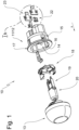
- a cooking appliance light is provided with the reference number 10 and in figure 1 shown in exploded view.
- the cooking appliance light 10 shown comprises a cooking appliance lamp socket 11 formed by a socket stone 12 which forms a receiving recess 14 on its top side facing a lamp glass 13 .
- the receiving recess 14 is delimited by a wall 15 and has an insertion opening 16 which is surrounded by a mounting flange 17 .
- a retaining ring 18 that can be inserted into the receiving recess 14 serves to fix the cooking device lamp socket 11 in a light recess of a cooking device wall.
- the retaining ring 18 also fixes the lamp glass 13 to the socket stone 12 and provides a retaining spring by means of which the lamp base 19 of a G9 lamp is locked in a socket recess of the socket stone 12 .
- the socket stone 12 On its underside facing away from the lamp glass 13, the socket stone 12 forms two sockets 21, each of which holds a socket contact 22 and a supply contact 23 in a manner to be described later.
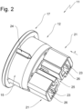
- FIG 2 shows the cooking appliance lamp socket 11 in a perspective view of its underside.
- the wall 15 carries a centering rib 24, by means of which the cooking appliance lamp socket 11 can be arranged in the correct position in the cooking appliance.
- the sockets 21 of the setting stone 12 are separated from one another by a ventilation gap 25 and each have a contact cavity 26.
- Each contact cavity 26 is accessible via an insertion opening 27, via each of which a socket contact 22 and a supply contact 23 can be introduced into the respective contact cavity 26 in the direction of insertion X.
- the insertion openings 27 are on the underside of the setting stone 12.
- the direction of insertion X is directed toward the lamp glass 12.
- figure 3 12 now shows the cooking appliance lamp socket 11 viewed from below, ie in the direction of insertion X.
- the insertion openings 27 of the contact cavities 26 can be seen very well in this representation.
- this representation allows an insight into the contact cavities 26 and the supply contact 23 located in each contact cavity and the socket contact 22 also located there.
- FIG. 1b shows the the figure 1 Removed arrangement of seated in the socket 21 socket contacts 22 and supply contacts 23 in an enlarged view.
- Each socket contact 22 has a flat plug 30 on its end facing the insertion opening 27. This is followed in the insertion direction X, ie in the direction of the lamp glass 13, by a clamping section 31 from which clamping lugs 32 are released.
- a contact section 34 is then arranged in front of the clamping section 31 and carries two fastening means 33 in the form of fastening arms 35 which are opposite one another and hold the clamping section 31 between them.
- the fastening arm 35 stretches from the contact section 34 counter to the insertion direction X in the direction of the underside of the socket stone 12 or in the direction of the flat plug 30.
- the direction of the lamp glass 13 or in the direction of insertion X forward lying end face 36 of the supply contact 23 serves as a support structure for fixing the socket contact 22.
- the supply contact 23 is a stamped and bent part with an essentially plate-like shape.
- the clamping lugs 32 are exhibited at an angle to the rolling sides.
- the mounting arms are in Figure 1B exhibited at an angle to the punched edges.
- the socket contact 22 also a stamped and bent part, has an approximately U-shaped or C-shaped cross-sectional contour.
- a first contact leg 40 is connected to a second contact leg 42 via a support leg 41, with the free ends of the first contact leg 40 and the second contact leg 42 moving counter to the insertion direction X in the direction of the insertion opening 27 of the socket 21, i.e. in the direction of the underside of the socket stone 12 are directed.
- the first contact limb 40 has a pressure spring 43 which is notched out of the material of the contact limb and is exhibited in a resiliently restoring manner in the direction of the second contact limb 42, ie in the interior of the U-shaped socket contact 22.
- the second contact leg 42 of the socket contact 22 is resiliently elastic away from the first contact leg 40, ie in the same direction as the pressure spring 43 is issued.
- figure 7 shows the setting stone 12 in a vertical sectional view along section line VV in figure 3 , In which case the representation of the seated socket contacts 22 and the seated supply contacts 23 has also been dispensed with here.
- each connecting piece 21 forms a contact cavity 26 which is accessible via an insertion opening 27 .
- a first accommodation space 50 and a second accommodation space 51 are formed within each contact cavity 26 .
- the first receiving space 50 runs through the contact cavity 26 as a diametrically extending slot 52 through the contact cavity 26, which is opposite to the insertion direction X, ie in the direction of the insertion opening 27, open.
- the second receiving space is arranged between the slot ends and shares a common receiving section 53 with the first receiving space.
- the location of the receiving spaces 50, 51 in the socket 21 of the socket stone 12 is also once again from figure 8 out, which is a sectional view according to VIII-VIII in figure 7 is.
- the socket contacts 22 and supply contacts 23 are not shown.
- the slot-like first receiving space 50 passes through the second receiving space 51.
- the common receiving space 53 is formed, in which the end face 36 meets the support leg 41 when the socket and supply contacts 22, 23 are inserted.
- the arrangement of socket contact and supply contact 23 in the receiving spaces 50, 51 then corresponds to that in figure 3 shown contact arrangement.
- FIG 5 shows the sectional view accordingly figure 7 with socket and supply contacts 22, 23 seated in the respective contact cavity 26 of each socket 21.
- the socket contact 22 must first be inserted into the second receiving space 51 in the insertion direction X in the socket block 12.
- the free end of the first contact leg 40 engages behind a protruding retaining lug 28, which is formed by the wall of the contact cavity 26, whereas the free end of the second contact leg 42 is located on an in figure 5 not visible wall section supports.
- the socket contact 22 experiences such a Prefixing that prevents the same from accidentally slipping out of the setting stone 12 during assembly.
- the supply contact 23 is pushed into the first receiving space 50, the slot 52.
- the insertion movement of the supply contact 23 in the insertion direction X ends when the end face 36 comes to rest on the inside of the support leg 51 of the socket contact 22, which sits in the common receiving section 53 of the first receiving space 50 and the second receiving space 51.
- the pressure spring 43 rests against the contact section 34 of the supply contact 23 and ensures the required electrical contact between socket contact 22 and supply contact 23.
- the second contact leg 42 of socket contact 22 sits in socket receptacle 29 of socket insulator 12, so that the socket contacts of a lamp in this embodiment of a G9 lamp 20 can contact them electrically.
- figure 4 shows the setting stone 12 together with the contacts used according to the section line IV-IV in FIG figure 3 .
- the supply contact 23 is pushed into the contact cavity 26 of the socket 21 in the insertion direction X and rests with its end face 36 on the support leg 41 of the socket contact 22 and holds it in the second receiving space 51 .
- the fastening arms 35 of the supply contact 23 because of their lateral spread directed towards the contact cavity wall, engage behind a fastening contour formed by the contact cavity wall, which is formed here as a wall projection 54 .
- a socket base 55 formed by socket insulator 12 serves as a movement limit stop in plug-in direction X, which delimits contact cavities 26 in plug-in direction X (see also figure 5 ).
- fastening arms 35 are spring-loaded fastening means that are spread outwards, i.e. in the direction of the contact cavity wall, these are initially displaced inwards when the supply contact 23 is pushed into the respective connection piece 21 until they have slid past the wall projection 54 .
- the spring-return elasticity of the material then leads to a spreading movement in the initial position, whereby the wall projection 54 is gripped behind, so that a pull-out movement of the supply contact 23 counter to the insertion direction X from the setting block 12 is reliably prevented.
- the fastening means are designed as plastically deformable fastening arms, they point in a straight line, ie not spread, before the completed assembly of the supply contact 23, against the insertion direction X or in the direction of the flat plug 30.
- a forming tool is inserted between the respective fastening arm 35 and the clamping section 31 located between the fastening arms 35, which spreads the fastening arms 35 outwards in the sense of plastic deformation until they securely grip behind the wall projection 54 and a retraction movement of the supply contact 23 counter to the insertion direction X is certain impede.
Description
- Die Erfindung betrifft eine Gargeräte-Lampenfassung,
- mit einem Fassungsstein,
- mit wenigstens einem Versorgungskontakt, der der Anbindung eines Anschlussleiters zur Spannungsversorgung einer Lampe dient,
- mit wenigstens einem Fassungskontakt, der mit dem Versorgungskontakt elektrisch verbunden ist und der Anbindung eines Sockelkontaktes der Lampe dient,
- mit einer vom Fassungsstein ausgebildeten Kontakthöhle, in welcher der Fassungskontakt angeordnet ist,
- mit einem Befestigungsmittel, mittels dessen der Versorgungskontakt am Fassungsstein befestigt ist
- wobei das Befestigungsmittel einstückiger und/oder stoffschlüssiger Bestandteil des Versorgungskontaktes ist, und
- wobei der Fassungsstein (12) eine Befestigungskontur aufweist, in welche das Befestigungsmittel des Versorgungskontaktes eingreift.
- Solche Lampenfassungen sind im Stand der Technik weit verbreitet. Sie nehmen Lampen verschiedener Normen, insbesondere mit Stecksockeln wie G9 Standard oder Schraubsockel mit E14 oder E39 Standard auf, um beispielsweise die Innenräume von Gargeräten auszuleuchten. Die Fassung wird beispielweise mittels eines metallenen Halterings in einer Leuchtenausnehmung einer Wand des Gargerätes festgelegt und mit einem Leuchtenglas abgedeckt. In der Regel befindet sich das Leuchtenglas im Garraum, wohingegen die Fassung außerhalb des Garraums angeordnet ist. Eine solche Gargeräteleuchte ist beispielsweise in der Anmeldereigenen
DE 10 2006 002 667 A1 beschrieben und weist als Bestandteil eine Fassung gemäß dem Oberbegriff des Anspruchs 1 auf. - An ihrem dem Leuchtenglas bzw. der Lampe abgewandten Ende ist die Fassung mit zwei Versorgungskontakten versehen, die dem Anschluss an eine externe Energieversorgung dienen und hierzu mit entsprechenden Anschlussleitern versehen werden.
- Die Versorgungskontakte wiederum stehen mit Fassungskontakten in Verbindung, die in einer Sockelausnehmung des Fassungssteins einsitzen und mit Sockelkontakten der Lampe eine elektrische Verbindung eingehen.
- Gattungsgemäße Lampenfassungen werden in der Regel als Massenware hergestellt, wobei unter Kostengesichtspunkten ein möglichst hoher Automatisierungsgrad und somit eine den Automatisierungsanforderungen gerecht werdende Fassungskonstruktion für den wirtschaftlichen Erfolg solcher Fassungen entscheidend ist.
- In
WO 2011/028053 A2 undUS 4,804,343 A sind Leuchten gezeigt, bei welchen der Fassungskontakt und der Versorgungskontakt einstückig ausgebildet sind und im Fassungsstein verrasten. -
EP 0 320 875 A2 offenbart eine Gargeräte-Lampenfassung. - Aufgabe der Erfindung ist es, eine gattungsgemäße Gargeräte-Lampenfassung in ihrer Konstruktion zu vereinfachen.
- Gelöst wird die Erfindung von einer Gargeräte-Lampenfassung mit den Merkmalen des Anspruchs 1, insbesondere mit dessen kennzeichnenden Merkmalen, wonach der Versorgungskontakt und der Fassungskontakt zwei voneinander getrennte Bauteile sind und der Fassungskontakt von dem am Fassungsstein festgelegten Versorgungskontakt gehalten ist.
- Die Erfindung hat erkannt, dass die im Stand der Technik verwendete Befestigung der Versorgungskontakte am Fassungsstein optimierbar ist.
- Bislang werden die Versorgungskontakte am Fassungsstein positioniert, woraufhin mit einem separaten Befestigungsmittel, beispielsweise einem Niet oder einer Schraube die Befestigung vorgenommen werden muss. Häufig ist für die lagegerechte Positionierung wie auch für den eigentlichen Befestigungsvorgang Handarbeit erforderlich. Trägt - wie erfindungsgemäß vorgeschlagen - der Versorgungskontakt das Befestigungsmittel selbst, insbesondere wenn das Befestigungsmittel einstückiger und oder stoffschlüssiger Bestandteil des Versorgungskontaktes ist, ist eine Ausrichtung des Befestigungsmittels zum Versorgungskontakt nicht weiter erforderlich, so dass dieser äußerste Präzision erfordernde und somit aufwendige Arbeitsschritt entfallen kann. Beispielsweise ist es denkbar, dass der Versorgungskontakt einen stoffschlüssig angebundenen Niet trägt und dieser nach dem Positionieren des Versorgungskontaktes am Fassungsstein durch ein entsprechendes Werkzeug in eine Nietausnehmung eingepresst wird. Hierbei kann sich der Niet vom Versorgungskontakt lösen.
- Der Versorgungskontakt und der Fassungskontakt sind zwei voneinander getrennte Bauteile und der Fassungskontakt von dem am Fassungsstein festgelegten Versorgungskontakt gehalten ist.
- Es ist im druckschriftlich nicht belegbaren Stand der Technik zwar durchaus üblich, den Versorgungskontakt und den Fassungskontakt mit dem selben Befestigungsmittel am Fassungsstein festzulegen, also beispielsweise beide Kontakt mit entsprechenden Nietöffnungen fluchtend zu positionieren und dann den Niet oder alternativ die Schraube zur Befestigung in den Fassungsstein einzusetzen. Dies erhöht jedoch den Aufwand insoweit, da zwei Kontakte lagegerecht zu positionieren sind. Die erfindungsgemäße Lösung hat den wesentlichen Vorteil, dass der Versorgungskontakt den Fassungskontakt lagegerecht hält und lediglich der Versorgungskontakt mit den erfindungsgemäß angebundenen Befestigungsmitteln am Fassungsstein festgelegt wird, dieses Befestigungsmittel den Fassungskontakt jedoch lediglich mittelbar am Fassungsstein anordnet.
- Die Erfindung sieht weiterhin vor, dass der Versorgungskontakt in der Kontakthöhle angeordnet ist und über eine Einstecköffnung der Kontakthöhle zugänglich ist. Hierdurch wird nicht nur die Sicherheit der Fassung erhöht, indem die Berührung der Versorgungskontakte durch Personen erschwer bzw. ausgeschlossen ist, insbesondere wenn die Versorgungskontakte vollständig innerhalb der Kontakthöhle einsitzen. Diese Art der Fassungskonstruktion erleichtert darüber hinaus die Festlegung des Fassungskontaktes durch den Versorgungskontakt.
- Konkret ist deshalb vorgesehen, dass die Befestigungskontur von den Wänden der Kontakthöhle ausgebildet ist und von dem Befestigungsmittel des Versorgungskontaktes hintergriffen ist.
- Hierbei bewährt es sich, wenn das Befestigungsmittel als wenigstens ein am Versorgungskontakt angebundener plastisch verformbarer oder rückstellelastischer Befestigungsarm ausgebildet ist. Für die automatisierte Montage ist es also von erheblichem Vorteil, wenn rückstellelastische Befestigungsarme vorgesehen sind, die als Rastmittel fungieren. Alternativ ist es denkbar, dass nach Einsetzen der Versorgungskontakte in den Fassungsstein, insbesondere in die Kontakthöhle des Fassungssteins, mittels eines Werkzeugs die Befestigungsarme plastisch derart verformt werden, so dass sie eine korrespondieren Befestigungskontur hintergreifen.
- Infolgedessen ist vorgesehen, dass die Befestigungskontur als Wandvorsprung ausgebildet ist, welche vom Befestigungsarm hintergriffen ist.
- Um eine sichere und konstruktiv vorteilhafte Festlegung des Fassungskontaktes durch den Versorgungskontakt zu gewährleisten ist vorgesehen, dass die Kontakthöhle einen ersten Aufnahmeraum für den Fassungskontakt und einen zweiten Aufnahmeraum für den Versorgungskontakt aufweist und dass der erste Aufnahmeraum und der zweite Aufnahmeraum einen gemeinsamen Aufnahmeabschnitt miteinander teilen, insbesondere wenn der Fassungskontakt und der Versorgungskontakt im gemeinsamen Aufnahmeabschnitt einsitzen und der Fassungskontakt sich am Versorgungskontakt abstützend gehalten ist.
- Besonders bevorzugt ist die Festlegung des Fassungskontaktes durch den Versorgungskontakt, wenn der Fassungskontakt und der Versorgungskontakt entlang einer gemeinsamen Einsteckrichtung durch die Einstecköffnung in die Kontakthöhle eingesetzt sind und der Fassungskontakt dem Versorgungskontakt in Einsteckrichtung vorgeordnet ist.
- Weitere Vorteile der Erfindung sowie ein besseres Verständnis derselben folgt aus der nachfolgenden Beschreibung eines Ausführungsbeispiels. Es zeigen:
-
Fig. 1 eine Gargeräteleuchte mit einer Gargeräte-Lampenfassung nach vorliegender Erfindung, -
Fig. 1b Darstellung der Anordnung von Fassungs- und Versorgungskontakten gemäßFigur 1 , -
Fig. 2 eine perspektivische Ansicht der Gargeräte-Lampenfassung ausFigur 1 , -
Fig. 3 eine Ansicht auf die Gargeräte-Lampenfassung von unten, also in Einsteckrichtung des Fassungskontaktes, -
Fig. 4 eine Schnittdarstellung der Gargeräte-Lampenfassung gemäß Schnittlinie IV-IV inFigur 3 , -
Fig. 5 eine Schnittdarstellung der Gargeräte-Lampenfassung gemäß Schnittlinie V-V inFigur 3 , -
Fig. 6 die Darstellung gemäßFigur 5 in perspektivischer Ansicht und -
Fig. 7 Schnittdarstellung des Fassungssteins entsprechendFigur 5 ohne Darstellung der Fassungs- und Versorgungskontakte. - In den Figuren ist eine Gargeräteleuchte insgesamt mit der Bezugsziffer 10 versehen und in
Figur 1 in Explosionsansicht dargestellt. - Die in
Figur 1 dargestellte Gargeräteleuchte 10 umfasst eine Gargeräte-Lampenfassung 11 gebildet durch einen Fassungsstein 12, der an seiner einem Leuchtenglas 13 zugewandten Oberseite eine Aufnahmeausnehmung 14 ausbildet. Die Aufnahmeausnehmung 14 wird von einer Wand 15 umgrenzt und verfügt über eine Einsetzöffnung 16, die von einem Montageflansch 17 umgeben ist. - Ein in die Aufnahmeausnehmung 14 einsetzbarer Haltering 18 dient der Festlegung der Gargeräte-Lampenfassung 11 in einer Leuchtenausnehmung einer Gargerätewandung. Der Haltering 18 legt darüber hinaus das Leuchtenglas 13 am Fassungsstein 12 fest und stellt eine Haltefeder bereit, mittels derer der Lampensockel 19 einer G9-Lampe in einer Fassungsausnehmung des Fassungssteins 12 verrastet wird.
- An seiner dem Leuchtenglas 13 abgewandten Unterseite bildet der Fassungsstein 12 zwei Stutzen 21 aus, die je einen Fassungskontakt 22 und einen Versorgungskontakt 23 in später noch zu beschreibender Weise halten.
-
Figur 2 zeigt die Gargeräte-Lampenfassung 11 in perspektivischer Ansicht auf ihre Unterseite. Zunächst erkennt man, dass die Wand 15 eine Zentrierrippe 24 trägt, mittels derer die Gargeräte-Lampenfassung 11 lagekorrekt im Gargerät anordenbar ist. - Die Stutzen 21 des Fassungssteins 12 sind durch einen Belüftungsspalt 25 voneinander getrennt und verfügen über jeweils eine Kontakthöhle 26. Jede Kontakthöhle 26 ist über eine Einstecköffnung 27 zugänglich, über welche jeweils ein Fassungskontakt 22 und ein Versorgungskontakt 23 in Einsteckrichtung X in die jeweilige Kontakthöhle 26 einbringbar sind.
- Im Ausführungsbeispiel befinden sich die Einstecköffnungen 27 auf der Unterseite des Fassungssteins 12. Die Einsteckrichtung X ist zum Leuchtenglas 12 hin gerichtet. Dies ist zwar eine bevorzugte und äußerst vorteilhafte Ausführungsform, eine abweichende Ausrichtung der Einstecköffnungen 27 des jeweiligen Stutzens 21 ist jedoch denkbar, womit sich dann auch die Einsteckrichtung X in ihrer Ausrichtung ändert.
-
Figur 3 zeigt nunmehr die Gargeräte-Lampenfassung 11 in Ansicht von unten, also in Einsteckrichtung X. Man kann dieser Darstellung unter anderem sehr gut die Einstecköffnungen 27 der Kontakthöhlen 26 entnehmen. Außerdem erlaubt diese Darstellung eine Einsicht in die Kontakthöhlen 26 und den in jeder Kontakthöhle einsitzenden Versorgungskontakt 23 und den dort ebenfalls einsitzenden Fassungskontakt 22. -
Figur 1b zeigt die derFigur 1 entnommene Anordnung der in den Stutzen 21 einsitzenden Fassungskontakte 22 und Versorgungskontakte 23 in vergrößerter Darstellung. Jeder Fassungskontakt 22 verfügt auf seinem zur Einstecköffnung 27 gelegenen Ende zunächst über einen Flachstecker 30. An diesen schließt sich in Einsteckrichtung X, also in Richtung Leuchtenglas 13 ein Einspannabschnitt 31 an, aus welchem Klemmnasen 32 ausgeklinkt sind. Sodann ist im Einspannabschnitt 31 ein Kontaktabschnitt 34 vorgeordnet, welche zwei einander gegenüberliegende und den Einspannabschnitt 31 zwischen sich aufnehmende Befestigungsmittel 33 in Form von Befestigungsarmen 35 trägt. Dabei streckt sich hier der Befestigungsarm 35 vom Kontaktabschnitt 34 entgegen der Einsteckrichtung X in Richtung Unterseite des Fassungssteins 12 bzw. in Richtung Flachstecker 30. Die in Richtung Leuchtenglas 13 gerichtete bzw. in Einsteckrichtung X vorn liegende Stirnfläche 36 des Versorgungskontaktes 23 dient als Stützstruktur zur Festlegung des Fassungskontaktes 22. - Der Versorgungskontakt 23 ist in seiner konkreten Ausgestaltung ein Stanzbiegeteil mit einer im wesentlichen plattenartigen Formgebung. Die Klemmnasen 32 sind winkelig zu den Walzseiten ausgestellt. Die Befestigungsarme sind in
Figur 1B winkelig zu den Stanzkanten ausgestellt. - Der Fassungskontakt 22, ebenfalls ein Stanzbiegeteil, weist eine in etwa U-förmige oder C-förmige Querschnittskontur auf. Ein erster Kontaktschenkel 40 ist über einen Stützschenkel 41 mit einem zweiten Kontaktschenkel 42 verbunden, wobei sich die freien Enden des ersten Kontaktschenkels 40 und des zweiten Kontaktschenkels 42 entgegen der Einsteckrichtung X in Richtung der Einstecköffnung 27 der Stutzen 21, also in Richtung Unterseite des Fassungssteins 12 gerichtet sind.
- Der erste Kontaktschenkel 40 verfügt über eine Andruckfeder 43, die aus dem Kontaktschenkelmaterial ausgeklinkt und federrückstellelastisch in Richtung des zweiten Kontaktschenkels 42, also in den Innenraum des U-förmigen Fassungskontaktes 22 ausgestellt ist.
- Der zweite Kontaktschenkel 42 des Fassungskontaktes 22 ist federrückstellelastisch vom ersten Kontaktschenkel 40 weg, also richtungsgleich mit der Andruckfeder 43 ausgestellt.
-
Figur 7 zeigt den Fassungsstein 12 in einer vertikalen Schnittansicht gemäß Schnittlinie V-V inFigur 3 , wobei hier zunächst auch die Darstellung der einsitzenden Fassungskontakte 22 sowie der einsitzenden Versorgungskontakte 23 verzichtet worden ist. - Jeder Stutzen 21 bildet, wie bereits dargestellt, eine Kontakthöhle 26 aus, die über eine Einstecköffnung 27 zugänglich ist. Innerhalb jeder Kontakthöhle 26 ist ein erster Aufnahmeraum 50 und ein zweiter Aufnahmeraum 51 ausgebildet. Der erste Aufnahmeraum 50 durchzieht die Kontakthöhle 26 als diametral durch die Kontakthöhle 26 verlaufender Schlitz 52, der entgegen der Einsteckrichtung X, also in Richtung Einstecköffnung 27, offen ist. Der zweite Aufnahmeraum ist zwischen den Schlitzenden angeordnet und teilt sich mit dem ersten Aufnahmeraum einen gemeinsamen Aufnahmeabschnitt 53.
- Die Lage der Aufnahmeräumen 50, 51 in den Stutzen 21 des Fassungssteins 12 geht auch noch einmal aus
Figur 8 hervor, welches eine Schnittdarstellung gemäß VIII-VIII inFigur 7 ist. Auf die Darstellung der Fassungskontakte 22 und Versorgungskontakte 23 wurde verzichtet. Der schlitzartige erste Aufnahmeraum 50 durchsetzt den zweiten Aufnahmeraum 51. Dort wo beide Aufnahmeräume 50, 51 einander überlappen, entsteht der gemeinsame Aufnahmeraum 53, in welchem bei eingesetzten Fassungs- und Versorgungskontakten 22, 23 die Stirnfläche 36 auf den Stützschenkel 41 trifft. Die Anordnung von Fassungskontakt und Versorgungskontakt 23 in den Aufnahmeräumen 50, 51 entspricht dann der inFigur 3 dargestellten Kontaktanordnung. -
Figur 5 zeigt die Schnittdarstellung entsprechendFigur 7 mit in der jeweiligen Kontakthöhle 26 eines jeden Stutzens 21 einsitzenden Fassungs- und Versorgungskontakten 22, 23. Dieser Darstellung ist nun zunächst zu entnehmen, dass zuerst der Fassungskontakt 22 in den zweiten Aufnahmeraum 51 in Einsteckrichtung X in den Fassungsstein 12 einzubringen ist. Dabei hintergreift das freie Ende des ersten Kontaktschenkels 40 eine vorspringende Haltenase 28, die von der Wand der Kontakthöhle 26 ausgebildet ist, wohingegen sich das freie Ende des zweiten Kontaktschenkels 42 an einem inFigur 5 nicht sichtbaren Wandabschnitt abstützt. Der Fassungskontakt 22 erfährt so eine Vorfixierung, die ein unbeabsichtigtes Herausrutschen desselben aus dem Fassungsstein 12 während der Montage verhindert. - Im Anschluss daran wird der Versorgungskontakt 23 in den ersten Aufnahmeraum 50, den Schlitz 52 eingeschoben. Die Einschubbewegung des Versorgungskontaktes 23 in Einschubrichtung X endet, wenn die Stirnfläche 36 auf der Innenseite des Stützschenkels 51 des Fassungskontaktes 22 zur Anlage kommt, welcher im gemeinsamen Aufnahmeabschnitt 53 von erstem Aufnahmeraum 50 und zweitem Aufnahmeraum 51 einsitzt. Die Andruckfeder 43 liegt am Kontaktabschnitt 34 des Versorgungskontaktes 23 an und sorgt für die erforderliche elektrische Kontaktierung zwischen Fassungskontakt 22 und Versorgungskontakt 23. Der zweite Kontaktschenkel 42 des Fassungskontaktes 22 sitzt in der Sockelaufnahme 29 des Fassungssteins 12 ein, so dass die Sockelkontakte einer Lampe, in diesem Ausführungsbeispiel einer G9-Lampe 20 diese elektrisch kontaktieren können.
- Der oben beschriebene Sachverhalt ist sodann nochmals in
Figur 6 dargestellt, welche den entsprechendFigur 5 geschnittenen Fassungsstein 12 in perspektivischer Schnittansicht zeigt. - Die vorangegangene Beschreibung zusammen mit den Figuren, insbesondere den
Figuren 5 bis 7 lässt bereits deutlich erahnen, dass eine Festlegung des Versorgungskontaktes 23 im Fassungsstein 12 zu einer Befestigung des Fassungskontaktes 22 durch den Versorgungskontakt 23 im Fassungsstein 12 führt. Der Fassungskontakt 22 ist so lediglich mittelbar durch die erfindungsgemäßen Befestigungsmittel 33 des Versorgungskontaktes 23 festgelegt. - Die Befestigung des Versorgungskontaktes 23 am Fassungsstein 12 wird nunmehr anhand von
Figur 4 erläutert. -
Figur 4 zeigt den Fassungsstein 12 nebst eingesetzten Kontakten entsprechend der Schnittlinie IV-IV inFigur 3 . - Der Versorgungskontakt 23 ist in Einsteckrichtung X in die Kontakthöhle 26 des Stutzens 21 eingeschoben und liegt mit seiner Stirnfläche 36 am Stützschenkel 41 des Fassungskontaktes 22 an und hält diesen in dem zweiten Aufnahmeraum 51 fest. Die Befestigungsarme 35 des Versorgungskontaktes 23 hintergreifen aufgrund ihrer seitlichen, zur Kontakthöhlenwand gerichteten Spreizung eine von der Kontakthöhlenwand ausgebildete Befestigungskontur, die hier als Wandvorsprung 54 ausgebildet ist.
- Als Bewegungsendanschlag in Einsteckrichtung X dient ein vom Fassungsstein 12 ausgebildeter Fassungsboden 55, der die Kontakthöhlen 26 in Einsteckrichtung X begrenzt (siehe auch
Figur 5 ). - Handelt es sich bei den Befestigungsarmen 35 um federrückstellelastisch nach außen, also in Richtung Kontakthöhlenwandung gespreizte Befestigungsmittel, werden diese beim Einschieben des Versorgungskontaktes 23 in den jeweiligen Stutzen 21 zunächst nach innen verdrängt, bis sie am Wandvorsprung 54 vorbei geglitten sind. Die Federrückstellelastizität des Materials führt dann zu einer Spreizbewegung in Ausgangslage, wodurch der Wandvorsprung 54 hintergriffen wird, so dass eine Auszugsbewegung des Versorgungskontaktes 23 entgegen der Einsteckrichtung X aus dem Fassungsstein 12 hinaus sicher verhindert ist.
- Sind die Befestigungsmittel hingegen als plastisch verformbare Befestigungsarme ausgeführt, so weisen diese vor der abgeschlossenen Montage des Versorgungskontaktes 23 geradlinig, d.h. ungespreizt, entgegen der Einsteckrichtung X bzw. in Richtung Flachstecker 30. Nach dem Einsetzen des Versorgungskontaktes 23 in die Kontakthöhle 26 wird dann ein Umformwerkzeug zwischen den jeweiligen Befestigungsarm 35 und den zwischen den Befestigungsarmen 35 gelegenen Einspannabschnitt 31 eingeschoben, welches im Sinne einer plastischen Verformung die Befestigungsarme 35 nach außen spreizt, bis diese den Wandvorsprung 54 sicher hintergreifen und eine Rückzugsbewegung des Versorgungskontaktes 23 entgegen der Einsteckrichtung X sicher verhindern.
-
- 10
- Gargeräteleuchte
- 11
- Gargeräte-Lampenfassung
- 12
- Fassungsstein
- 13
- Leuchtenglas
- 14
- Aufnahmeausnehmung
- 15
- Wand
- 16
- Einsetzöffnung
- 17
- Montageflansch
- 18
- Haltering
- 19
- Lampensockel
- 20
- G9-Lampe
- 21
- Stutzen
- 22
- Fassungskontakt
- 23
- Versorgungskontakt
- 24
- Zentrierrippe
- 25
- Belüftungsspalt
- 26
- Kontakthöhlen
- 27
- Einstecköffnung
- 28
- Haltenase
- 29
- Sockelaufnahme
- 30
- Flachstecker
- 31
- Einspannabschnitt
- 32
- Klemmnase
- 33
- Befestigungsmittel
- 34
- Kontaktabschnitt
- 35
- Befestigungsarm
- 36
- Stirnfläche
- 40
- erster Kontaktschenkel
- 41
- Stützschenkel
- 42
- zweiter Kontaktschenkel
- 43
- Andruckfeder
- 50
- erster Aufnahmeraum
- 51
- zweiter Aufnahmeraum
- 52
- Schlitz
- 53
- gemeinsamer Aufnahmeabschnitt
- 54
- Wandvorsprung
Claims (12)
- Gargeräte-Lampenfassung (11),- mit einem Fassungsstein (12),- mit wenigstens einem Versorgungskontakt (23), der der Anbindung eines Anschlussleiters zur Spannungsversorgung einer Lampe dient,- mit wenigstens einem Fassungskontakt (22), der mit dem Versorgungskontakt (23) elektrisch verbunden ist und der Anbindung eines Sockelkontaktes der Lampe dient,- mit einer vom Fassungsstein (12) ausgebildeten Kontakthöhle (26), in welcher der Fassungskontakt (22) angeordnet ist,- mit einem Befestigungsmittel (33), mittels dessen der Versorgungskontakt (23) am Fassungsstein (12) befestigt ist,- wobei das Befestigungsmittel (33) einstückiger und/oder stoffschlüssiger Bestandteil des Versorgungskontaktes (23) ist, und- wobei der Fassungsstein (12) eine Befestigungskontur aufweist, in welche das Befestigungsmittel (33) des Versorgungskontaktes (23) eingreift,dadurch gekennzeichnet, dass- der Versorgungskontakt (23) und der Fassungskontakt (22) zwei voneinander getrennte Bauteile sind,- der Fassungskontakt (22) von dem am Fassungsstein (12) festgelegten Versorgungskontakt (23) gehalten ist.
- Gargeräte-Lampenfassung nach Anspruch 1, dadurch gekennzeichnet, dass der Fassungsstein (12) an seiner zu einem Leuchtenglas (13) zugewandten Oberseite eine Aufnahmeausnehmung (14) aufweist.
- Gargeräte-Lampenfassung nach Anspruch 2, dadurch gekennzeichnet, dass in der Aufnahmeausnehmung (14) ein Haltering (18) einsitzt, der die Gargeräte-Lampenfassung (11) in einer Leuchtenausnehmung eines Gargerätes hält.
- Gargeräte-Lampenfassung (11) nach einem der Ansprüche 1 bis 3, dadurch gekennzeichnet, dass der Versorgungskontakt (23) in der Kontakthöhle (26) angeordnet ist und über eine Einstecköffnung (27) der Kontakthöhle (26) zugänglich ist.
- Gargeräte-Lampenfassung (11) nach Anspruch 2 und 4, dadurch gekennzeichnet, dass die Befestigungskontur von den Wänden der Kontakthöhle (26) ausgebildet ist und von dem Befestigungsmittel (33) des Versorgungskontaktes (23) hintergriffen ist.
- Gargeräte-Lampenfassung (11) nach einem der vorhergehenden Ansprüche, dadurch gekennzeichnet, dass das Befestigungsmittel (33) als wenigstens ein am Versorgungskontakt (23) angebundener plastisch verformbarer oder rückstellelastischer Befestigungsarm (35) ausgebildet ist.
- Gargeräte-Lampenfassung (11) nach Anspruch 2, 4, 5 und 6, dadurch gekennzeichnet, dass die Befestigungskontur als Wandvorsprung ausgebildet ist, welche vom Befestigungsarm (35) hintergriffen ist.
- Gargeräte-Lampenfassung (11) nach Anspruch 1 und 4, dadurch gekennzeichnet, dass die Kontakthöhle (26) einen ersten Aufnahmeraum (50) für den Fassungskontakt (22) und einen zweiten Aufnahmeraum (51) für den Versorgungskontakt (23) aufweist und dass der erste Aufnahmeraum (50) und der zweite Aufnahmeraum (51) einen gemeinsamen Aufnahmeabschnitt (53) miteinander teilen.
- Gargeräte-Lampenfassung (11) nach Anspruch 3 und 8, dadurch gekennzeichnet, dass der Fassungskontakt (22) und der Versorgungskontakt (23) im gemeinsamen Aufnahmeabschnitt (53) einsitzen und der Fassungskontakt (22) sich am Versorgungskontakt (23) abstützend gehalten ist.
- Gargeräte-Lampenfassung (11) nach Anspruch 9, dadurch gekennzeichnet, dass der Fassungskontakt (22) und der Versorgungskontakt (23) entlang einer gemeinsamen Einsteckrichtung (X) durch die Einstecköffnung (27) in die Kontakthöhle (26) eingesetzt sind und der Fassungskontakt (22) dem Versorgungskontakt (23) in Einsteckrichtung (X) vorgeordnet ist.
- Gargeräte-Lampenfassung nach Anspruch 4, dadurch gekennzeichnet, dass sich die Einstecköffnung (27) auf der Unterseite des Fassungssteins (12) befindet.
- Gargeräte-Lampenfassung nach Anspruch 10 und 11, dadurch gekennzeichnet, dass die Einsteckrichtung in Richtung eines Leuchtenglases (13) gerichtet ist.
Applications Claiming Priority (1)
| Application Number | Priority Date | Filing Date | Title |
|---|---|---|---|
| DE102021112796.3A DE102021112796B3 (de) | 2021-05-18 | 2021-05-18 | Lampenfassung mit ungenieteter Kontaktanbindung |
Publications (2)
| Publication Number | Publication Date |
|---|---|
| EP4092837A1 EP4092837A1 (de) | 2022-11-23 |
| EP4092837B1 true EP4092837B1 (de) | 2023-08-16 |
Family
ID=80449142
Family Applications (1)
| Application Number | Title | Priority Date | Filing Date |
|---|---|---|---|
| EP22158398.2A Active EP4092837B1 (de) | 2021-05-18 | 2022-02-24 | Gargeräte-lampenfassung mit ungenieteter kontaktanbindung |
Country Status (5)
| Country | Link |
|---|---|
| US (1) | US11843207B2 (de) |
| EP (1) | EP4092837B1 (de) |
| CN (1) | CN115377765A (de) |
| DE (1) | DE102021112796B3 (de) |
| PL (1) | PL4092837T3 (de) |
Citations (1)
| Publication number | Priority date | Publication date | Assignee | Title |
|---|---|---|---|---|
| EP0320875A2 (de) * | 1987-12-15 | 1989-06-21 | Bosch-Siemens HausgerÀ¤te GmbH | Elektrische Beleuchtungseinrichtung für Hausgeräte, wie Backöfen |
Family Cites Families (7)
| Publication number | Priority date | Publication date | Assignee | Title |
|---|---|---|---|---|
| US3810072A (en) | 1972-11-22 | 1974-05-07 | Microdot Inc | Socket |
| US4804343A (en) * | 1988-04-11 | 1989-02-14 | General Motors Corporation | Lamp socket assembly |
| DE19860588C2 (de) * | 1998-12-29 | 2001-03-01 | Schnippering Hugo Gmbh Co Kg | Lampenfassung aus Isolierstoff für H 7-Lampen |
| DE29922089U1 (de) | 1999-12-16 | 2000-03-30 | Bjb Gmbh & Co Kg | Elektrischer Anschlußkontakt und Lampenfassung mit einem solchen Kontakt |
| DE102006002667B4 (de) | 2006-01-19 | 2007-11-29 | Bjb Gmbh & Co.Kg | Elektrische Leuchte, insbesondere zum Einbau in Küchengeräte |
| KR101614543B1 (ko) * | 2009-09-07 | 2016-04-22 | 타이코에이엠피 주식회사 | 웨지벌브용 소켓 |
| FR2977391B1 (fr) * | 2011-06-30 | 2016-08-05 | Tbi | Douille hybride pour ampoule mono-filament ou bi-filament |
-
2021
- 2021-05-18 DE DE102021112796.3A patent/DE102021112796B3/de active Active
-
2022
- 2022-02-24 PL PL22158398.2T patent/PL4092837T3/pl unknown
- 2022-02-24 EP EP22158398.2A patent/EP4092837B1/de active Active
- 2022-03-20 US US17/699,127 patent/US11843207B2/en active Active
- 2022-04-18 CN CN202210401195.5A patent/CN115377765A/zh active Pending
Patent Citations (1)
| Publication number | Priority date | Publication date | Assignee | Title |
|---|---|---|---|---|
| EP0320875A2 (de) * | 1987-12-15 | 1989-06-21 | Bosch-Siemens HausgerÀ¤te GmbH | Elektrische Beleuchtungseinrichtung für Hausgeräte, wie Backöfen |
Also Published As
| Publication number | Publication date |
|---|---|
| US20220376449A1 (en) | 2022-11-24 |
| PL4092837T3 (pl) | 2024-02-19 |
| US11843207B2 (en) | 2023-12-12 |
| CN115377765A (zh) | 2022-11-22 |
| EP4092837A1 (de) | 2022-11-23 |
| DE102021112796B3 (de) | 2022-06-23 |
Similar Documents
| Publication | Publication Date | Title |
|---|---|---|
| DE10126957B4 (de) | Steckverbindung mit Mitteln zur Verhinderung eines unvollständig verbundenen Zustands | |
| EP1662620A2 (de) | Elektrische Steckverbindung | |
| DE2409075A1 (de) | Elektrischer verbinder | |
| EP1275173A1 (de) | Stecker mit einer hülse | |
| DE4022876A1 (de) | Anschlussbefestigungsvorrichtung | |
| DE2811774A1 (de) | Elektrischer buchsenkontakt | |
| DE102012109059B4 (de) | Halterung eines Leuchtmittels in der Öffnung eines Reflektors | |
| DE10163057B4 (de) | Fassung für Hochvoltlampen | |
| EP4092837B1 (de) | Gargeräte-lampenfassung mit ungenieteter kontaktanbindung | |
| DE4205974C1 (en) | Electrical plug connector with built-in latching for pins - provides section formed on housing that locates against pin flange and is held by latch stage | |
| WO2020212122A1 (de) | Federkraftklemme und verfahren zum herstellen einer federklemme | |
| EP3633802A1 (de) | Gerätesteckdose, gerätestecker und gerätesteckersystem | |
| DE19860588C2 (de) | Lampenfassung aus Isolierstoff für H 7-Lampen | |
| EP1443609B1 (de) | Einrichtung zur Befestigung eines Steckverbinderkontakteinsatzes in einem Steckverbindergehäuse | |
| DE202021102681U1 (de) | Lampenfassung mit ungenieteter Kontaktanbindung | |
| EP1528639A1 (de) | Steckverbindergehäuse mit Kurzschlussbrücke | |
| EP1302720A2 (de) | Lampenfassung sowie Baugruppe bestehend aus Lampenfassung und Reflektor | |
| EP3015359A1 (de) | Vorrichtung zur Fixierung und elektrischen Kontaktierung eines Verkleidungselements eines Luftfahrzeugs an einer Tragstruktur | |
| EP1401062B1 (de) | Hausgeräte-Steckkontaktsystem | |
| BE1026101B1 (de) | Kontaktelement mit einem Kontaktkörper und einem daran angeordneten Federelement | |
| EP0664583A1 (de) | Fassung für Kleinglühlampe | |
| EP1734620B1 (de) | Mittelkontakt für eine Glühlampenfassung | |
| EP1610056B1 (de) | Verbindungsvorrichtung zum lösbaren Verbinden einer Lampe | |
| WO2019086066A1 (de) | Steckverbinder | |
| DE102006022206B3 (de) | Elektrischer Steckanschluß |
Legal Events
| Date | Code | Title | Description |
|---|---|---|---|
| PUAI | Public reference made under article 153(3) epc to a published international application that has entered the european phase |
Free format text: ORIGINAL CODE: 0009012 |
|
| STAA | Information on the status of an ep patent application or granted ep patent |
Free format text: STATUS: THE APPLICATION HAS BEEN PUBLISHED |
|
| STAA | Information on the status of an ep patent application or granted ep patent |
Free format text: STATUS: REQUEST FOR EXAMINATION WAS MADE |
|
| AK | Designated contracting states |
Kind code of ref document: A1 Designated state(s): AL AT BE BG CH CY CZ DE DK EE ES FI FR GB GR HR HU IE IS IT LI LT LU LV MC MK MT NL NO PL PT RO RS SE SI SK SM TR |
|
| 17P | Request for examination filed |
Effective date: 20221114 |
|
| RBV | Designated contracting states (corrected) |
Designated state(s): AL AT BE BG CH CY CZ DE DK EE ES FI FR GB GR HR HU IE IS IT LI LT LU LV MC MK MT NL NO PL PT RO RS SE SI SK SM TR |
|
| STAA | Information on the status of an ep patent application or granted ep patent |
Free format text: STATUS: EXAMINATION IS IN PROGRESS |
|
| 17Q | First examination report despatched |
Effective date: 20230126 |
|
| GRAP | Despatch of communication of intention to grant a patent |
Free format text: ORIGINAL CODE: EPIDOSNIGR1 |
|
| STAA | Information on the status of an ep patent application or granted ep patent |
Free format text: STATUS: GRANT OF PATENT IS INTENDED |
|
| RIC1 | Information provided on ipc code assigned before grant |
Ipc: H01R 13/428 20060101ALN20230406BHEP Ipc: H01R 4/48 20060101ALN20230406BHEP Ipc: H01R 33/06 20060101ALI20230406BHEP Ipc: H01R 13/432 20060101ALI20230406BHEP Ipc: H01R 13/08 20060101AFI20230406BHEP |
|
| INTG | Intention to grant announced |
Effective date: 20230510 |
|
| GRAS | Grant fee paid |
Free format text: ORIGINAL CODE: EPIDOSNIGR3 |
|
| GRAA | (expected) grant |
Free format text: ORIGINAL CODE: 0009210 |
|
| STAA | Information on the status of an ep patent application or granted ep patent |
Free format text: STATUS: THE PATENT HAS BEEN GRANTED |
|
| AK | Designated contracting states |
Kind code of ref document: B1 Designated state(s): AL AT BE BG CH CY CZ DE DK EE ES FI FR GB GR HR HU IE IS IT LI LT LU LV MC MK MT NL NO PL PT RO RS SE SI SK SM TR |
|
| REG | Reference to a national code |
Ref country code: CH Ref legal event code: EP |
|
| REG | Reference to a national code |
Ref country code: DE Ref legal event code: R096 Ref document number: 502022000089 Country of ref document: DE |
|
| REG | Reference to a national code |
Ref country code: IE Ref legal event code: FG4D Free format text: LANGUAGE OF EP DOCUMENT: GERMAN |
|
| REG | Reference to a national code |
Ref country code: LT Ref legal event code: MG9D |
|
| REG | Reference to a national code |
Ref country code: NL Ref legal event code: MP Effective date: 20230816 |
|
| P01 | Opt-out of the competence of the unified patent court (upc) registered |
Effective date: 20231211 |
|
| PG25 | Lapsed in a contracting state [announced via postgrant information from national office to epo] |
Ref country code: GR Free format text: LAPSE BECAUSE OF FAILURE TO SUBMIT A TRANSLATION OF THE DESCRIPTION OR TO PAY THE FEE WITHIN THE PRESCRIBED TIME-LIMIT Effective date: 20231117 |
|
| PG25 | Lapsed in a contracting state [announced via postgrant information from national office to epo] |
Ref country code: IS Free format text: LAPSE BECAUSE OF FAILURE TO SUBMIT A TRANSLATION OF THE DESCRIPTION OR TO PAY THE FEE WITHIN THE PRESCRIBED TIME-LIMIT Effective date: 20231216 |
|
| PG25 | Lapsed in a contracting state [announced via postgrant information from national office to epo] |
Ref country code: SE Free format text: LAPSE BECAUSE OF FAILURE TO SUBMIT A TRANSLATION OF THE DESCRIPTION OR TO PAY THE FEE WITHIN THE PRESCRIBED TIME-LIMIT Effective date: 20230816 Ref country code: RS Free format text: LAPSE BECAUSE OF FAILURE TO SUBMIT A TRANSLATION OF THE DESCRIPTION OR TO PAY THE FEE WITHIN THE PRESCRIBED TIME-LIMIT Effective date: 20230816 Ref country code: PT Free format text: LAPSE BECAUSE OF FAILURE TO SUBMIT A TRANSLATION OF THE DESCRIPTION OR TO PAY THE FEE WITHIN THE PRESCRIBED TIME-LIMIT Effective date: 20231218 Ref country code: NO Free format text: LAPSE BECAUSE OF FAILURE TO SUBMIT A TRANSLATION OF THE DESCRIPTION OR TO PAY THE FEE WITHIN THE PRESCRIBED TIME-LIMIT Effective date: 20231116 Ref country code: NL Free format text: LAPSE BECAUSE OF FAILURE TO SUBMIT A TRANSLATION OF THE DESCRIPTION OR TO PAY THE FEE WITHIN THE PRESCRIBED TIME-LIMIT Effective date: 20230816 Ref country code: LV Free format text: LAPSE BECAUSE OF FAILURE TO SUBMIT A TRANSLATION OF THE DESCRIPTION OR TO PAY THE FEE WITHIN THE PRESCRIBED TIME-LIMIT Effective date: 20230816 Ref country code: LT Free format text: LAPSE BECAUSE OF FAILURE TO SUBMIT A TRANSLATION OF THE DESCRIPTION OR TO PAY THE FEE WITHIN THE PRESCRIBED TIME-LIMIT Effective date: 20230816 Ref country code: IS Free format text: LAPSE BECAUSE OF FAILURE TO SUBMIT A TRANSLATION OF THE DESCRIPTION OR TO PAY THE FEE WITHIN THE PRESCRIBED TIME-LIMIT Effective date: 20231216 Ref country code: HR Free format text: LAPSE BECAUSE OF FAILURE TO SUBMIT A TRANSLATION OF THE DESCRIPTION OR TO PAY THE FEE WITHIN THE PRESCRIBED TIME-LIMIT Effective date: 20230816 Ref country code: GR Free format text: LAPSE BECAUSE OF FAILURE TO SUBMIT A TRANSLATION OF THE DESCRIPTION OR TO PAY THE FEE WITHIN THE PRESCRIBED TIME-LIMIT Effective date: 20231117 Ref country code: FI Free format text: LAPSE BECAUSE OF FAILURE TO SUBMIT A TRANSLATION OF THE DESCRIPTION OR TO PAY THE FEE WITHIN THE PRESCRIBED TIME-LIMIT Effective date: 20230816 |
|
| PG25 | Lapsed in a contracting state [announced via postgrant information from national office to epo] |
Ref country code: ES Free format text: LAPSE BECAUSE OF FAILURE TO SUBMIT A TRANSLATION OF THE DESCRIPTION OR TO PAY THE FEE WITHIN THE PRESCRIBED TIME-LIMIT Effective date: 20230816 |
|
| PG25 | Lapsed in a contracting state [announced via postgrant information from national office to epo] |
Ref country code: SM Free format text: LAPSE BECAUSE OF FAILURE TO SUBMIT A TRANSLATION OF THE DESCRIPTION OR TO PAY THE FEE WITHIN THE PRESCRIBED TIME-LIMIT Effective date: 20230816 Ref country code: RO Free format text: LAPSE BECAUSE OF FAILURE TO SUBMIT A TRANSLATION OF THE DESCRIPTION OR TO PAY THE FEE WITHIN THE PRESCRIBED TIME-LIMIT Effective date: 20230816 Ref country code: ES Free format text: LAPSE BECAUSE OF FAILURE TO SUBMIT A TRANSLATION OF THE DESCRIPTION OR TO PAY THE FEE WITHIN THE PRESCRIBED TIME-LIMIT Effective date: 20230816 Ref country code: EE Free format text: LAPSE BECAUSE OF FAILURE TO SUBMIT A TRANSLATION OF THE DESCRIPTION OR TO PAY THE FEE WITHIN THE PRESCRIBED TIME-LIMIT Effective date: 20230816 Ref country code: DK Free format text: LAPSE BECAUSE OF FAILURE TO SUBMIT A TRANSLATION OF THE DESCRIPTION OR TO PAY THE FEE WITHIN THE PRESCRIBED TIME-LIMIT Effective date: 20230816 Ref country code: CZ Free format text: LAPSE BECAUSE OF FAILURE TO SUBMIT A TRANSLATION OF THE DESCRIPTION OR TO PAY THE FEE WITHIN THE PRESCRIBED TIME-LIMIT Effective date: 20230816 Ref country code: SK Free format text: LAPSE BECAUSE OF FAILURE TO SUBMIT A TRANSLATION OF THE DESCRIPTION OR TO PAY THE FEE WITHIN THE PRESCRIBED TIME-LIMIT Effective date: 20230816 |
|
| PGFP | Annual fee paid to national office [announced via postgrant information from national office to epo] |
Ref country code: DE Payment date: 20240130 Year of fee payment: 3 |