EP4092371B1 - Wärmerohr mit verbesserter leistung unter verschiedenen wärmelastverteilungen - Google Patents
Wärmerohr mit verbesserter leistung unter verschiedenen wärmelastverteilungen Download PDFInfo
- Publication number
- EP4092371B1 EP4092371B1 EP22174302.4A EP22174302A EP4092371B1 EP 4092371 B1 EP4092371 B1 EP 4092371B1 EP 22174302 A EP22174302 A EP 22174302A EP 4092371 B1 EP4092371 B1 EP 4092371B1
- Authority
- EP
- European Patent Office
- Prior art keywords
- heat pipe
- longitudinal
- circumferential
- channel
- pipe according
- Prior art date
- Legal status (The legal status is an assumption and is not a legal conclusion. Google has not performed a legal analysis and makes no representation as to the accuracy of the status listed.)
- Active
Links
Images



Classifications
-
- F—MECHANICAL ENGINEERING; LIGHTING; HEATING; WEAPONS; BLASTING
- F28—HEAT EXCHANGE IN GENERAL
- F28D—HEAT-EXCHANGE APPARATUS, NOT PROVIDED FOR IN ANOTHER SUBCLASS, IN WHICH THE HEAT-EXCHANGE MEDIA DO NOT COME INTO DIRECT CONTACT
- F28D15/00—Heat-exchange apparatus with the intermediate heat-transfer medium in closed tubes passing into or through the conduit walls ; Heat-exchange apparatus employing intermediate heat-transfer medium or bodies
- F28D15/02—Heat-exchange apparatus with the intermediate heat-transfer medium in closed tubes passing into or through the conduit walls ; Heat-exchange apparatus employing intermediate heat-transfer medium or bodies in which the medium condenses and evaporates, e.g. heat pipes
- F28D15/0233—Heat-exchange apparatus with the intermediate heat-transfer medium in closed tubes passing into or through the conduit walls ; Heat-exchange apparatus employing intermediate heat-transfer medium or bodies in which the medium condenses and evaporates, e.g. heat pipes the conduits having a particular shape, e.g. non-circular cross-section, annular
-
- F—MECHANICAL ENGINEERING; LIGHTING; HEATING; WEAPONS; BLASTING
- F28—HEAT EXCHANGE IN GENERAL
- F28D—HEAT-EXCHANGE APPARATUS, NOT PROVIDED FOR IN ANOTHER SUBCLASS, IN WHICH THE HEAT-EXCHANGE MEDIA DO NOT COME INTO DIRECT CONTACT
- F28D15/00—Heat-exchange apparatus with the intermediate heat-transfer medium in closed tubes passing into or through the conduit walls ; Heat-exchange apparatus employing intermediate heat-transfer medium or bodies
- F28D15/02—Heat-exchange apparatus with the intermediate heat-transfer medium in closed tubes passing into or through the conduit walls ; Heat-exchange apparatus employing intermediate heat-transfer medium or bodies in which the medium condenses and evaporates, e.g. heat pipes
- F28D15/0275—Arrangements for coupling heat-pipes together or with other structures, e.g. with base blocks; Heat pipe cores
-
- F—MECHANICAL ENGINEERING; LIGHTING; HEATING; WEAPONS; BLASTING
- F28—HEAT EXCHANGE IN GENERAL
- F28D—HEAT-EXCHANGE APPARATUS, NOT PROVIDED FOR IN ANOTHER SUBCLASS, IN WHICH THE HEAT-EXCHANGE MEDIA DO NOT COME INTO DIRECT CONTACT
- F28D15/00—Heat-exchange apparatus with the intermediate heat-transfer medium in closed tubes passing into or through the conduit walls ; Heat-exchange apparatus employing intermediate heat-transfer medium or bodies
- F28D15/02—Heat-exchange apparatus with the intermediate heat-transfer medium in closed tubes passing into or through the conduit walls ; Heat-exchange apparatus employing intermediate heat-transfer medium or bodies in which the medium condenses and evaporates, e.g. heat pipes
- F28D15/0283—Means for filling or sealing heat pipes
-
- F—MECHANICAL ENGINEERING; LIGHTING; HEATING; WEAPONS; BLASTING
- F28—HEAT EXCHANGE IN GENERAL
- F28D—HEAT-EXCHANGE APPARATUS, NOT PROVIDED FOR IN ANOTHER SUBCLASS, IN WHICH THE HEAT-EXCHANGE MEDIA DO NOT COME INTO DIRECT CONTACT
- F28D15/00—Heat-exchange apparatus with the intermediate heat-transfer medium in closed tubes passing into or through the conduit walls ; Heat-exchange apparatus employing intermediate heat-transfer medium or bodies
- F28D15/02—Heat-exchange apparatus with the intermediate heat-transfer medium in closed tubes passing into or through the conduit walls ; Heat-exchange apparatus employing intermediate heat-transfer medium or bodies in which the medium condenses and evaporates, e.g. heat pipes
- F28D15/04—Heat-exchange apparatus with the intermediate heat-transfer medium in closed tubes passing into or through the conduit walls ; Heat-exchange apparatus employing intermediate heat-transfer medium or bodies in which the medium condenses and evaporates, e.g. heat pipes with tubes having a capillary structure
- F28D15/046—Heat-exchange apparatus with the intermediate heat-transfer medium in closed tubes passing into or through the conduit walls ; Heat-exchange apparatus employing intermediate heat-transfer medium or bodies in which the medium condenses and evaporates, e.g. heat pipes with tubes having a capillary structure characterised by the material or the construction of the capillary structure
-
- F—MECHANICAL ENGINEERING; LIGHTING; HEATING; WEAPONS; BLASTING
- F28—HEAT EXCHANGE IN GENERAL
- F28F—DETAILS OF HEAT-EXCHANGE AND HEAT-TRANSFER APPARATUS, OF GENERAL APPLICATION
- F28F2220/00—Closure means, e.g. end caps on header boxes or plugs on conduits
Definitions
- the invention relates to heat pipes, heat transfer devices, in particular for cooling a heating element.
- a heat pipe generally comprises a central axial channel in which vaporous working fluid moves, and longitudinal grooves extending axially and around the central axial channel, intended to advance the liquid working fluid in a direction opposite that of the vapor.
- the circumferential transfer channel allows the grooves adjacent to the most stressed groove(s) to contribute to the liquid fluid supply function. Liquid passes through the circumferential transfer channel from a less stressed groove to a more stressed groove. This helps to push back the thermal load limits that could lead to partial or total drying of one or more of the most stressed grooves.
- the most thermally stressed parts are those where the vaporization flow/rate is greatest.
- the longitudinal path (PX) can be straight or non-straight. If the path is not straight, the axial direction is therefore local and not an absolute direction.
- circumferential transfer channel (6) generally appears as an annular passage. In practice, it often appears as an annular groove.
- longitudinal channels are made as longitudinal grooves, generally obtained by extrusion and made in one piece with the main profiled body.
- the circumferential transfer channel can fluidly connect all the longitudinal channels, in which the annular passage actually makes a complete turn. But it is not excluded that in particular configurations with thermal loads known in advance, the circumferential transfer channel fluidly connects the longitudinal channels over half the circumference (only half a turn) or over one or more arbitrary angular ranges.
- section of the longitudinal channels can have various possible shapes, the bottom not necessarily being flat, the walls not necessarily being straight.
- section of the longitudinal channels has a general concavity.
- section of the longitudinal channels can generally be in the shape of an arc of a circle or an arc of an oval.
- the section of the longitudinal channels can be trapezoidal.
- one and/or the other of the following arrangements may optionally be further used, taken alone or in combination.
- the circumferential transfer channel runs all the way around and connects all the longitudinal channels with fluid. This provides consistent and predictable behavior regardless of the load distribution around the heat pipe. Regardless of the most thermally loaded part of the circumference, the most thermally stressed groove(s) receive additional fluid from the other grooves via the circumferential transfer channel.
- circumferential transfer channels can be provided, arranged one after the other in the longitudinal direction. By means of this, it is possible to multiply the liquid redistribution effect and increase capillary pressure over an entire area.
- the cover ring discussed below can be dispensed with.
- the circumferential transfer channel can be delimited radially inwards by a cover ring, the cover ring then being interposed between the circumferential transfer channel and the axial channel.
- the presence of the cover ring makes it possible to promote the formation of liquid meniscus on its wall and the walls of adjacent low walls.
- the presence of the cover ring makes it possible to increase the capillary pressure at this axial position of the heat pipe.
- the design of the ring is optimized to limit local pressure losses in the longitudinal flow, on the liquid or on the vapor.
- the circumferential channel can be arranged at an intermediate position, the walls (2) being interrupted over a predefined length (L6) at this location.
- a circumferential channel in an intermediate position it can be produced as an annular passage by means of a material removal operation with a revolution tool such as a centrifugal cutter, or by electro-erosion or other general machining technique.
- the material of the walls (2) is preferably removed over a height (H6) of between 50% and 100% of the height (H2) of the walls.
- a wall base remains with a residual height (H7) of between 0% and 50% of the normal height (H2) of the walls.
- H7 residual height of between 0% and 50% of the normal height (H2) of the walls.
- the walls may comprise a first bearing area (B1) for receiving a first longitudinal end of the cover ring (4) and a second bearing area (B2) for receiving a second longitudinal end of the cover ring.
- B1 for receiving a first longitudinal end of the cover ring (4)
- B2 for receiving a second longitudinal end of the cover ring.
- the cover ring (4) may comprise a central excess thickness (45) forming a radially external shoulder received between the walls at the location of the first and second bearing zones (B1, B2).
- the cover ring (4) may have a constant thickness and the first and second bearing areas are then formed as flats (14) set back from the top of the walls.
- the ring is then a simple cylinder obtained by sawing a tube, a very cheap component.
- the cover ring (4) can be made of a deformable material, either in the elastic or plastic range, so that the cover ring can be introduced from one end of the profiled body to the first and second bearing areas, so that in the target position the cover ring closes the circumferential transfer channel radially inwards.
- the elastic force is released or a plastic force (deformation) is applied outwards to achieve the final positioning.
- the first position (P1) is chosen in the vicinity of an evaporation portion (71) of the heat pipe coupled to a hot source (81). This optimizes the effect of equalizing the pressures of the liquid phase in the longitudinal channels as close as possible to the zone where drying under high thermal load is to be avoided.
- the first position (P1) is an intermediate position on the longitudinal path. Said intermediate position being any on the longitudinal path, there is thus complete freedom to position the circumferential transfer channel (or circumferential channels) as close as possible to the need.
- the first position (P1) is an end position on the longitudinal path. In this configuration, it is easier to remove material from the walls to form the annular groove forming the transfer channel.
- the circumferential channel is formed in an end cap (5) attached to one end of the profiled body.
- the end cap no reworking is performed on the extruded profiled body.
- the complexity of the shapes and the attachment is carried by the end cap.
- one or more other circumferential channels are provided along the path, at distinct axial positions different from the first position.
- the multiple positions can be advantageously determined depending on the application or be distributed regularly in the longitudinal direction, over the whole or part of the heat pipe.
- the heat pipe may comprise a combination of circumferential channels, some arranged in an intermediate longitudinal position and some arranged in an end position. In other words, there is no incompatibility in having several circumferential channels of different types coexist.
- the heat pipe can include a combination of different types of circumferential channels.
- annular channels 360°
- partially annular channels ⁇ 360°
- the circumferential channels can be adapted to optimize the thermo-hydraulic performance.
- a plurality of circumferential channels may be provided along the path, at regularly spaced axial positions (P2, P3, P4), with a predetermined pitch, for example every 300 mm. This makes it possible to equalize the pressures of the liquid phase in all the grooves at regular intervals along the heat pipe.
- one or more intersections can be provided along the heat pipe route, with two circumferential channels arranged on either side of each intersection. This minimizes the a priori harmful effect of the intersection from the point of view of hydraulic continuity between the channels.
- the heat pipe can be presented as a three-dimensional object. It then extends through space in all three Cartesian dimensions, not just in a plane. This advantageously provides complete freedom of design and configuration to perfectly suit all possible applications.
- the proposed solutions there is no porous layer, porous mass, or porous coating in the proposed heat pipes, neither punctually nor generally along the length of the heat pipe.
- the proposed heat pipes are devoid of capillary porous material intended to ensure capillary pumping.
- a heat pipe 1 which takes calories from a hot source 81 and rejects them towards a cold source 82.
- the hot source 81 is in contact with the heat pipe at an evaporation portion 71.
- the cold source 82 is in contact with the heat pipe at a condensation portion 72.
- the heat pipe 1 is presented as an elongated device closed at a first end 11 by a closing element 50, and at a second end 12 by a second closing element 50.
- FIG. 3 another example is illustrated where the heat pipe receives the calories on one side of the heat pipe axis (from below in the illustrated example) and rejects the calories on the other side of the heat pipe axis (from above in the illustrated example).
- This is a configuration known in the art as a "Heat Spreader”.
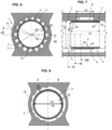
- the heat pipe 1 generally comprises a central axial channel 15 in which working fluid in the form of vapor moves, and longitudinal grooves extending axially and around the central axial channel. As illustrated in Figures 4 and 5 , the longitudinal grooves, also called longitudinal channels 3 are intended to advance the working fluid in liquid form in a direction opposite to that of the vapor.
- Heat pipe 1 is configured for use in low or zero gravity.
- this type of heat pipe is used in spacecraft and devices.
- this type of heat pipe is used in communications satellites, surveillance satellites, satellites with all types of other functions.
- Heat pipe 1 can be used in total weightlessness or in a low gravity situation, for example on the surface of a celestial body such as the Moon or Mars.
- Heat pipe 1 can be used with zero or very low external pressure.
- the heat pipe 1 comprises a profiled body 10 obtained by extrusion. Additional operations can be carried out as will be seen later. However, the extrusion operation is the main manufacturing operation. Using a press, an aluminum alloy is pushed through a die having the desired shapes to obtain the profiled body at the die outlet.
- the profiled body forms a hollow body which delimits an interior space hermetically isolated from the external environment, and which will be used to contain working fluid.
- the profiled body has a section which, after extrusion, extends identically along the longitudinal axis marked X.
- the profiled body can then be bent, so that the finished heat pipe is not necessarily straight.
- the profiled body 10 extends along a longitudinal path PX.
- the longitudinal path PX can be straight or curved.
- the length of the PX route can be between 0.5 meters and 10 meters.
- the profiled body 10 comprises a peripheral tubular wall 75, from which two diametrically opposed feet 16, 17 extend radially outwards. These feet each end in a support plane adapted to exchange calories with the cold or hot source 82, 81.
- the body could have four interface planes, and in a particular case the outer boundary of the body could be substantially square or totally cylindrical.
- the thermal coupling elements could be separate and added, as shown in figure 16
- the profile is generally of revolution around the X axis, with inside a repetition of the pattern [groove + wall] in the circumferential direction .
- the profiled body comprises a plurality of longitudinal channels 3.
- the longitudinal channels are made as longitudinal grooves.
- Each of said longitudinal channels has a section delimited by a bottom 76 formed by a peripheral tubular wall 75 of the profiled body, and laterally by two longitudinal walls 2 which extend radially inwards from the peripheral tubular wall.
- the longitudinal channels surround the central axial channel 15 conveying steam.
- the longitudinal channels 3 are generally open towards the axial channel,
- the longitudinal channels 3 are arranged annularly around the axis. However, non-circular arrangements are also possible.
- the peripheral tubular wall 75 has a primitive external diameter D0.
- D0 can be between 3 millimeters and 50 millimeters.
- the diameter D1 represents the internal dimension of the peripheral tubular wall 75, in other words the diameter taken at the level of the bottom of the grooves.
- the diameter D2 represents the internal dimension of the axial channel, in other words the diameter of the circumscribed circle passing through the top 77 of the walls.
- the interior space is perfectly hermetically isolated from the external environment, because the profile is a single piece and made of extruded material, it surrounds the interior space with continuous material, without any orifice.
- the working fluid may be ammonia, propylene, methanol or any other medium exhibiting a liquid-vapor equilibrium under saturation conditions at operating pressures defined by temperature.
- a predetermined quantity of working fluid is introduced through one of the end elements equipped with a sealable filling orifice.
- the pressure in the interior space of the heat pipe may range from 0.1 bar to several tens of bars.
- the predetermined amount of working fluid is set to preferably have limited excess liquid on the cold/condenser side, i.e. the grooves are completely filled and, if necessary, fill the end of the axial channel, cold side.
- the section of the longitudinal channels 3 can have any suitable shape, the bottom 76 not necessarily being flat, the walls not necessarily being straight.
- the section of the longitudinal channels has a general concavity.
- the section of the longitudinal channels can generally be in the shape of an arc of a circle or an arc of an oval, or even a drop shape open towards the axial channel 15.
- the section is in the shape of a trapezoidal section.
- At least one circumferential transfer channel 6 is provided, arranged transversely to the local axial direction.
- the circumferential transfer channel 6 is located at a first position P1 along the longitudinal path PX.
- the circumferential transfer channel 6 places all the longitudinal channels in fluid communication with each other. More generally, the circumferential transfer channel 6 places all or part of the plurality of longitudinal channels in communication with each other.
- the circumferential transfer channel 6 generally appears as an annular passage. In practice, it often appears as an annular groove, which forms a complete ring (360°) without excluding a smaller angular opening.
- the longitudinal walls 2 are interrupted at the location of the circumferential channel 6.
- the material of the walls has been removed to a depth H6.
- the circumferential transfer channel 6 has an axial length L6 .
- the axial length L6 of the circumferential channel can be, as in the example illustrated, greater than the height H2 of the grooves.
- the axial length L6 of the circumferential channel may be less than the height H2 of the grooves.
- H6 can be between 50% and 100% of the height H2.
- H6 can be between 70% and 100% of the height H2.
- a wall base remains at a residual height H7 of between 0% and 50% of the height H2 of the walls. Maintaining a wall base allows longitudinal contact lines to be maintained to channel the liquid by capillarity, notwithstanding the presence of the circumferential transfer channel.
- circumferential transfer channels can be provided, arranged one after the other in the longitudinal direction X. It could be envisaged to produce such a fairly tight succession of transverse channels of small longitudinal dimension (L6 small).
- the circumferential transfer channel 6 is delimited radially inwards by a cover ring 4.
- the cover ring 4 is interposed between the circumferential transfer channel and the axial channel.
- the cover ring 4 closes the circumferential transfer channel 6 radially towards the X axis.
- the cover ring 4 generally appears as a tubular body 40, otherwise called a sleeve.
- the cover ring 4 has an axial length L5 .
- the axial length L5 of the cover ring is in practice chosen to be slightly larger than the axial length L6 of the circumferential channel.
- the radial thickness E5 of the cover ring, at the level of the circumferential transfer channel, is between 0.1 millimeter and 1 millimeter.
- the external diameter of the ring at the circumferential channel is noted D5.
- the cover ring 4 can be made of a deformable material, either in the elastic or plastic domain, so that it can be installed in position to cover and radially close the circumferential channel 6.
- the ring is constrained radially inwards and then inserted by threading inside the axial channel and once it has reached the correct axial position (target position), the elastic constraint is released, which leads to expansion and final positioning.
- an initial diameter of the ring is chosen slightly smaller than D2, then the ring is inserted by threading inside the axial channel and once it has reached the correct axial position (target position), a radial expansion is caused by introducing a deformable tool. Then the cover ring is pressed against the walls or the bearing surfaces/flats provided for this purpose.
- a first bearing area B1 is provided to receive a first longitudinal end 41 of the cover ring 4 and a second bearing area B2 is provided to receive a second longitudinal end 42 of the cover ring.
- the cover ring 4 may comprise a central excess thickness 45 forming a radially external shoulder 47.
- the central excess thickness 45 is received between the walls on stop fronts 44 at the location of the first and second bearing zones.
- the cover ring has a constant thickness E4 and the first and second bearing areas B1, B2 are formed as flats 14 set back from the top of the walls.
- the diameter D4 is larger than D2, i.e. the ring is radially set back from the tops 77 of the walls.
- the flats 14 are obtained by removing material.
- the cover ring forms an additional contact line which increases the capillary pressure at the circumferential channel 6.
- the capillary pressure at the circumferential channel 6 is higher than the capillary pressure along the longitudinal channels 3.
- the ring allows the total recovery of the hydraulic section at the circumferential channel to ensure the continuity of the liquid flow.
- closure elements 50 which simply close the profiled body.
- the present invention provides for the clever use of the closure elements.
- the circumferential channel is formed in an end cap 5 fixed to one end of the profiled body.
- the cap comprises an inner sleeve 51 and a closing disc 52.
- the closing disc 52 is thick enough to withstand the internal pressure.
- the inner sleeve 51 does not support any substantial force, and it is sufficient that the axial length L65 of the sleeve is greater than the axial length L6 of the circumferential channel, to come flush with the tops 77 of the walls 2.
- the circumferential channel 6 is obtained by removing material from the walls on their end portion. This machining is relatively standard; it is sufficient to introduce a milling cutter with the prescribed diameter axially into the end portion of the body 10.
- the cap comprises an inner sleeve 51.
- the inner sleeve 51 may be separate from the closing disc 52 or else made according to a single-piece logic. When it is separate, the inner sleeve 51 is received in a circular housing 57 at the bottom of the closing disc, and is presented as an easy-to-obtain part: simple tubular sleeve.
- a watertight closing seal 53 is provided which connects the outer ferrule 54 of the cap 5 to the profiled body 10.
- the longitudinal walls 2 are interrupted at the location of the circumferential channel.
- the outer limit of the circumferential channel is formed by a thickness 56 of the plug projecting radially inwards.
- the first position P1 for the circumferential transfer channel is chosen in the vicinity of an evaporation portion 71 of the heat pipe coupled to a hot source.
- the circumferential transfer channel is filled with liquid and the pressure differences of the different grooves are equalized at this location.
- Menisci M are formed in the longitudinal channels, they are all the more hollowed out as the pressure difference is important along the length of the groove, in particular in the longitudinal direction, between the cold sources corresponding to the lowest pressures and the hot sources corresponding to the highest pressures.
- the meniscus is almost flat.
- the meniscus is more hollow.
- the meniscus is even more hollowed out.
- a meniscus forms in the circumferential transfer channel, allowing fluid to move in a circumferential direction and transit from one longitudinal channel to another.
- the ring As well as the bottom of the longitudinal canal initiate a meniscus.
- the Figure 14B illustrates the steady state where the entire volume of the circumferential transfer channel is filled with liquid.
- the meniscus forms in the circumferential channel only in transient conditions, and in steady state, it is the menisci of the longitudinal channels, deeper downstream than upstream, which generate the flow in the circumferential groove.
- the recirculation groove is designed to have higher capillary pumping than the longitudinal groove to prime with liquid properly.
- channel C1 is the most thermally stressed, it receives the calories by a short conductive path, it is at this point that the vaporization flow rate is the most important.
- the neighboring channels C2, CG also participate in the vaporization, but slightly less.
- the slightly more distant channels C2, CG and following participate a little less in the vaporization, depending on the intensity of the heat flow, until they no longer participate at all in the vaporization for the most distant grooves, when all the incoming flow has been vaporized.
- the presence of a circumferential transfer channel near the heat source allows liquid that has not arrived via C1 along its length to be transferred to channel C1.
- the neighboring channels supply liquid to the first channel C1.
- channels CG, C1, C2 will be supplied by all other channels, i.e. C3, C4, C5, C6, C7, C8, C9, CA, CB, CC, CD, CE, CF.
- the circumferential transfer channel has a function of pooling and sharing the liquid supply. It supplies liquid to the longitudinal channel 3 with the greatest demand, from the other channels.
- the closing ring promotes the supply of liquid to the circumferential transfer channel.
- the ring also promotes the passage in a straight line in a particular longitudinal channel.
- the closing ring is slightly set back from the top of the walls, it has a favorable effect on the straight passage of the liquid in a longitudinal channel.
- one or more other circumferential channels are provided on the path, at distinct axial positions (P2, P3, P4) different from the first position.
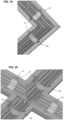
- the PX route may include one or more curves 18, and where appropriate may even include one or more right angles 19.
- FIG 19 represents a longitudinal half-section of the heat pipe in the vicinity of a right-angle connection with two circumferential transfer channels.
- two profiled bodies cut at 45° have been joined to form a right angle at this point; there is an imbalance in meniscus formation between the well-irrigated outer grooves and the rather dry inner grooves.
- the presence of one or two circumferential transfer channels in the vicinity of the angle makes it possible to equalize the pressures between the different longitudinal channels.
- FIG 20 represents a half longitudinal section of the heat pipe in the vicinity of a cross connection with 4 circumferential transfer channels.
- This configuration is an extrapolation of the previous case illustrated the figure 19 , with four profiles joined at a cross intersection.
- the presence of the four circumferential channels near the intersection makes it possible to equalize the pressures between the different longitudinal channels.
- external fixing sleeves are provided to ensure mechanical cohesion and sealing, generally obtained by welding.
- L6 being between 0.1 D0 and 0.5 D0.
- H2 between 0.05 D1 and 0.2 D1 can be chosen.
Landscapes
- Engineering & Computer Science (AREA)
- Life Sciences & Earth Sciences (AREA)
- Sustainable Development (AREA)
- Physics & Mathematics (AREA)
- Thermal Sciences (AREA)
- Mechanical Engineering (AREA)
- General Engineering & Computer Science (AREA)
- Heat-Exchange Devices With Radiators And Conduit Assemblies (AREA)
- Rigid Pipes And Flexible Pipes (AREA)
Claims (14)
- Wärmerohr (1), das dazu ausgebildet ist, bei geringer oder keiner Schwerkraft genutzt zu werden, umfassend einen im Allgemeinen durch Extrusion erhaltenen Profilkörper (10), wobei sich der Profilkörper entlang eines Längsverlaufs (PX) erstreckt, wobei der Profilkörper einen Hohlkörper bildet, der an wenigstens zwei Enden durch Verschlusselemente verschlossen ist wodurch ein Innenraum gebildet wird, der hermetisch von der äußeren Umgebung isoliert und mit einem vorgegebenen Volumen eines zweiphasigen Arbeitsfluids gefüllt ist,wobei der Profilkörper eine Vielzahl von Längskanälen (3) umfasst, die jeweils einen Querschnitt aufweisen, der durch einen Boden (76) begrenzt ist, der durch eine umlaufende Rohrwand (75) des Profilkörpers gebildet wird, und seitlich durch zwei Längswände (2), die sich von der umlaufenden Rohrwand radial nach innen erstrecken, wobei die Längskanäle einen Axialkanal (15) umgeben, wobei die Längskanäle zum Axialkanal hin offen sind,dadurch gekennzeichnet, dass an wenigstens einer ersten Position (P1) entlang des Längsverlaufs (PX) ein Umfangsübertragungskanal (6) vorgesehen ist, der quer zur lokalen axialen Richtung (X) angeordnet ist und die Mehrzahl der Längskanäle ganz oder teilweise miteinander in Fluidverbindung bringt,und dass die Längswände an der Stelle des Umfangskanals teilweise oder vollständig unterbrochen sind.
- Wärmerohr nach Anspruch 1, wobei der Umfangsübertragungskanal radial nach innen durch einen Abdeckring (4) begrenzt ist, wobei der Abdeckring zwischen dem Umfangsübertragungskanal und dem Axialkanal (15) angeordnet ist.
- Wärmerohr nach Anspruch 2, wobei der Umfangskanal an einer Zwischenposition angeordnet ist, wobei die Wände (2) auf einer vorbestimmten Länge (L6) an dieser Stelle unterbrochen sind, wobei vorzugsweise das Material der Wände (2) auf einer Höhe (H6) entfernt wurde, die zwischen 50 % und 100 % der Höhe (H2) der Wände beträgt.
- Wärmerohr nach Anspruch 3, wobei die Wände einen ersten Auflagebereich (B1) zur Aufnahme eines ersten Längsendes (41) des Abdeckrings (4) und einen zweiten Auflagebereich (B2) zur Aufnahme eines zweiten Längsendes (42) des Abdeckrings umfassen.
- Wärmerohr nach Anspruch 4, wobei der Abdeckring (4) eine zentrale Verdickung (45) aufweist, die eine radial äußere Schulter bildet, die zwischen den Wänden an der Stelle der ersten und zweiten Auflagefläche (B1, B2) aufgenommen ist.
- Wärmerohr nach Anspruch 4, wobei der Abdeckring (4) eine konstante Dicke aufweist und der erste und zweite Auflagebereich als vom Scheitelpunkt der Wände zurückgesetzte Abflachungen (14) ausgebildet sind.
- Wärmerohr nach einem der Ansprüche 1 bis 6, wobei die erste Position (P1) in der Nähe eines Verdampfungsabschnitts (71) des Wärmerohrs gewählt ist, das mit einer Wärmequelle (81) gekoppelt ist.
- Wärmerohr nach einem der Ansprüche 1 bis 7, wobei die erste Position (P1) eine Zwischenposition auf dem Längsweg (PX) ist.
- Wärmerohr nach einem der Ansprüche 1 bis 7, wobei die erste Position (P1) eine Endposition auf dem Längsweg ist.
- Wärmerohr nach einem der Ansprüche 1 bis 7, wobei der Umfangskanal in einem an einem Ende des Profilkörpers befestigten Endstopfen (5) ausgebildet ist.
- Wärmerohr nach einem der Ansprüche 1 bis 10, wobei ein oder mehrere weitere Umfangskanäle auf dem Verlauf an axialen Positionen (P2, P3, P4) vorgesehen sind, die von der ersten Position getrennt und verschieden sind.
- Wärmerohr nach einem der Ansprüche 1 bis 10, wobei eine Vielzahl von Umfangskanälen auf dem Weg an axialen Positionen (P2, P3, P4) in regelmäßigen Abständen mit einem vorbestimmten Abstand vorgesehen ist, beispielsweise alle 300 mm.
- Wärmerohr nach einem der Ansprüche 1 bis 12, das einen oder mehrere Schnittpunkte mit zwei Umfangskanälen aufweist, die auf beiden Seiten jedes Schnittpunkts angeordnet sind.
- Wärmerohr nach einem der Ansprüche 1 bis 13, das als dreidimensionales Objekt ausgebildet ist.
Applications Claiming Priority (1)
| Application Number | Priority Date | Filing Date | Title |
|---|---|---|---|
| FR2105276A FR3123114B1 (fr) | 2021-05-20 | 2021-05-20 | Caloduc à performance améliorée sous diverses répartitions de charges thermiques |
Publications (2)
| Publication Number | Publication Date |
|---|---|
| EP4092371A1 EP4092371A1 (de) | 2022-11-23 |
| EP4092371B1 true EP4092371B1 (de) | 2025-04-02 |
Family
ID=77411788
Family Applications (1)
| Application Number | Title | Priority Date | Filing Date |
|---|---|---|---|
| EP22174302.4A Active EP4092371B1 (de) | 2021-05-20 | 2022-05-19 | Wärmerohr mit verbesserter leistung unter verschiedenen wärmelastverteilungen |
Country Status (5)
| Country | Link |
|---|---|
| US (1) | US12173967B2 (de) |
| EP (1) | EP4092371B1 (de) |
| JP (1) | JP7844254B2 (de) |
| ES (1) | ES3023509T3 (de) |
| FR (1) | FR3123114B1 (de) |
Families Citing this family (3)
| Publication number | Priority date | Publication date | Assignee | Title |
|---|---|---|---|---|
| FR3069627B1 (fr) * | 2017-07-26 | 2020-06-26 | Valeo Systemes Thermiques | Echangeur de chaleur et systeme thermique pour vehicule automobile |
| US12305929B2 (en) * | 2023-02-06 | 2025-05-20 | Westinghouse Electric Company Llc | Advanced manufacturing heat pipe segment with integral printed wick |
| FR3167995A1 (fr) | 2024-10-29 | 2026-05-01 | Euro Heat Pipes | Caloduc flexible |
Citations (1)
| Publication number | Priority date | Publication date | Assignee | Title |
|---|---|---|---|---|
| US6216343B1 (en) * | 1999-09-02 | 2001-04-17 | The United States Of America As Represented By The Secretary Of The Air Force | Method of making micro channel heat pipe having corrugated fin elements |
Family Cites Families (39)
| Publication number | Priority date | Publication date | Assignee | Title |
|---|---|---|---|---|
| JPH04340089A (ja) * | 1991-05-15 | 1992-11-26 | Furukawa Electric Co Ltd:The | ヒートパイプ |
| JPH0587475A (ja) * | 1991-09-27 | 1993-04-06 | Furukawa Electric Co Ltd:The | ヒートパイプ式冷却器 |
| JP2732755B2 (ja) * | 1992-06-24 | 1998-03-30 | 宇宙開発事業団 | 二重管ヒートパイプ |
| JPH08219667A (ja) * | 1995-02-13 | 1996-08-30 | Hitachi Ltd | ヒートパイプ |
| JP3591339B2 (ja) * | 1998-11-16 | 2004-11-17 | 三菱電機株式会社 | ループ型ヒートパイプ |
| JP2001221584A (ja) * | 2000-02-10 | 2001-08-17 | Mitsubishi Electric Corp | ループ型ヒートパイプ |
| US7775261B2 (en) * | 2002-02-26 | 2010-08-17 | Mikros Manufacturing, Inc. | Capillary condenser/evaporator |
| TWI271502B (en) * | 2005-01-28 | 2007-01-21 | Foxconn Tech Co Ltd | Wick structure for heat pipe and method for making thereof |
| US7086454B1 (en) * | 2005-03-28 | 2006-08-08 | Jaffe Limited | Wick structure of heat pipe |
| US7293601B2 (en) * | 2005-06-15 | 2007-11-13 | Top Way Thermal Management Co., Ltd. | Thermoduct |
| TWM278870U (en) * | 2005-06-21 | 2005-10-21 | Tai Sol Electronics Co Ltd | Heating pipe |
| DE202005021911U1 (de) * | 2005-08-24 | 2011-05-12 | Ohb System Ag | Wärmerohr |
| CN100498184C (zh) * | 2005-11-17 | 2009-06-10 | 富准精密工业(深圳)有限公司 | 热管 |
| CN100561105C (zh) * | 2006-02-17 | 2009-11-18 | 富准精密工业(深圳)有限公司 | 热管 |
| CN101055158A (zh) * | 2006-04-14 | 2007-10-17 | 富准精密工业(深圳)有限公司 | 热管 |
| CN100561108C (zh) * | 2006-04-14 | 2009-11-18 | 富准精密工业(深圳)有限公司 | 热管 |
| CN101093151B (zh) * | 2006-06-21 | 2010-04-14 | 富准精密工业(深圳)有限公司 | 热管 |
| CN101173843A (zh) * | 2006-11-01 | 2008-05-07 | 富准精密工业(深圳)有限公司 | 柔性热管 |
| CN101349519A (zh) * | 2007-07-18 | 2009-01-21 | 富准精密工业(深圳)有限公司 | 热管 |
| CN101349520B (zh) * | 2007-07-20 | 2010-12-29 | 富准精密工业(深圳)有限公司 | 热管的制造方法 |
| CN101398272A (zh) * | 2007-09-28 | 2009-04-01 | 富准精密工业(深圳)有限公司 | 热管 |
| US20090166004A1 (en) * | 2007-12-29 | 2009-07-02 | Fu Zhun Precision Industry (Shen Zhen) Co., Ltd. | Heat pipe |
| US8919427B2 (en) * | 2008-04-21 | 2014-12-30 | Chaun-Choung Technology Corp. | Long-acting heat pipe and corresponding manufacturing method |
| US20090308576A1 (en) * | 2008-06-17 | 2009-12-17 | Wang Cheng-Tu | Heat pipe with a dual capillary structure and manufacturing method thereof |
| CN101749977A (zh) * | 2008-12-22 | 2010-06-23 | 富瑞精密组件(昆山)有限公司 | 热导管及其制造方法 |
| JP5075273B2 (ja) * | 2009-02-24 | 2012-11-21 | 株式会社フジクラ | 扁平型ヒートパイプおよびその製造方法 |
| TW201038900A (en) * | 2009-04-21 | 2010-11-01 | Yeh Chiang Technology Corp | Sintered heat pipe |
| JP3166568U (ja) * | 2010-12-27 | 2011-03-10 | 洪 進興 | 径方向排流機能を備えたヒートパイプ |
| US20120175084A1 (en) * | 2011-01-09 | 2012-07-12 | Chin-Hsing Horng | Heat pipe with a radial flow shunt design |
| US20120227934A1 (en) * | 2011-03-11 | 2012-09-13 | Kunshan Jue-Chung Electronics Co. | Heat pipe having a composite wick structure and method for making the same |
| US9618275B1 (en) * | 2012-05-03 | 2017-04-11 | Advanced Cooling Technologies, Inc. | Hybrid heat pipe |
| US9404392B2 (en) * | 2012-12-21 | 2016-08-02 | Elwha Llc | Heat engine system |
| CN205092233U (zh) * | 2013-03-27 | 2016-03-16 | 古河电气工业株式会社 | 冷却装置 |
| US20170122673A1 (en) * | 2015-11-02 | 2017-05-04 | Acmecools Tech. Ltd. | Micro heat pipe and method of manufacturing micro heat pipe |
| JP6560425B1 (ja) * | 2018-11-09 | 2019-08-14 | 古河電気工業株式会社 | ヒートパイプ |
| TWI680274B (zh) * | 2019-01-31 | 2019-12-21 | 雙鴻科技股份有限公司 | 複合式熱管 |
| US11955249B2 (en) * | 2020-10-29 | 2024-04-09 | Westinghouse Electric Company Llc | Heat pipe having a wick between concentric inner and outer housings, for use in heat removal from a nuclear reactor core |
| JP6980081B1 (ja) * | 2020-11-13 | 2021-12-15 | 古河電気工業株式会社 | ヒートパイプ |
| JP7550682B2 (ja) * | 2021-03-05 | 2024-09-13 | 三菱重工業株式会社 | ヒートパイプ |
-
2021
- 2021-05-20 FR FR2105276A patent/FR3123114B1/fr active Active
-
2022
- 2022-05-19 EP EP22174302.4A patent/EP4092371B1/de active Active
- 2022-05-19 JP JP2022082259A patent/JP7844254B2/ja active Active
- 2022-05-19 ES ES22174302T patent/ES3023509T3/es active Active
- 2022-05-19 US US17/749,031 patent/US12173967B2/en active Active
Patent Citations (1)
| Publication number | Priority date | Publication date | Assignee | Title |
|---|---|---|---|---|
| US6216343B1 (en) * | 1999-09-02 | 2001-04-17 | The United States Of America As Represented By The Secretary Of The Air Force | Method of making micro channel heat pipe having corrugated fin elements |
Also Published As
| Publication number | Publication date |
|---|---|
| JP7844254B2 (ja) | 2026-04-13 |
| FR3123114B1 (fr) | 2023-07-14 |
| EP4092371A1 (de) | 2022-11-23 |
| JP2022179437A (ja) | 2022-12-02 |
| FR3123114A1 (fr) | 2022-11-25 |
| ES3023509T3 (en) | 2025-06-02 |
| US12173967B2 (en) | 2024-12-24 |
| US20220373265A1 (en) | 2022-11-24 |
Similar Documents
| Publication | Publication Date | Title |
|---|---|---|
| EP4092371A1 (de) | Wärmerohr mit verbesserter leistung unter verschiedenen wärmelastverteilungen | |
| CA2470449C (fr) | Procede de realisation d'un joint tubulaire etanche avec expansion plastique | |
| EP0867596B1 (de) | Gewindeverbinder für Rohre | |
| OA12828A (fr) | Joint fileté tubulaire renforcé pour étanchéité amélioré après expansion plastique. | |
| WO1994016272A1 (fr) | Element echangeur de chaleur, procede et dispositif pour le fabriquer | |
| FR2704168A1 (fr) | Mandrin de honage expansible modulaire. | |
| FR2996247A1 (fr) | Procede de fracturation hydraulique et materiel correspondant | |
| EP0282406B1 (de) | Vorrichtung, um das Ende eines in einem Rohr rotierenden beweglichen Elementes in Position zu halten, und Anwendung dieser Vorrichtung | |
| WO1987000457A1 (fr) | Outil d'expansion hydraulique pour element tubulaire | |
| FR3077622A1 (fr) | Appareil de chauffage thermodynamique d'une cuve | |
| WO2006114522A1 (fr) | Element thermostatique a reponse rapide, ainsi que cartouche et robinet equipes d’un tel element | |
| FR3121059A1 (fr) | Procédé de fabrication d’un échangeur de chaleur et échangeur de chaleur obtenu par un tel procédé | |
| EP3183498B1 (de) | Verbindungsvorrichtung mit mehreren gekrümmten konzentrischen rohren | |
| FR2759762A1 (fr) | Raccord isolant dielectrique et procede d'assemblage d'un tel raccord | |
| EP3156555B1 (de) | Aufhängung für dämmmaterial mit umkehrbarer verriegelung | |
| EP1509333B1 (de) | Düse zum spritzen eines produkts | |
| EP3917683B1 (de) | Behälter für ein flüssiges produkt | |
| FR2540613A1 (fr) | Dispositif de transmission de chaleur | |
| FR2702271A1 (fr) | Distributeur perfectionné pour échangeur de chaleur, comportant un garnissage anticorrosion. | |
| FR2876171A1 (fr) | Raccord de type noix pour echangeur de chaleur | |
| FR3148421A3 (fr) | Rouleau de transport, dispositif de transport, ensemble à vide | |
| FR2811643A1 (fr) | Corps de valve pour pulverisateur | |
| FR2761137A1 (fr) | Procede de raccordement d'elements tubulaires et installations ainsi realisees | |
| EP4433735A1 (de) | Druckelement für ein flüssigkeitstransportrohr mit einer inneren schutzauskleidung | |
| FR3077621A1 (fr) | Appareil de chauffage thermodynamique d'une cuve a condenseur optimise |
Legal Events
| Date | Code | Title | Description |
|---|---|---|---|
| PUAI | Public reference made under article 153(3) epc to a published international application that has entered the european phase |
Free format text: ORIGINAL CODE: 0009012 |
|
| STAA | Information on the status of an ep patent application or granted ep patent |
Free format text: STATUS: REQUEST FOR EXAMINATION WAS MADE |
|
| 17P | Request for examination filed |
Effective date: 20220519 |
|
| AK | Designated contracting states |
Kind code of ref document: A1 Designated state(s): AL AT BE BG CH CY CZ DE DK EE ES FI FR GB GR HR HU IE IS IT LI LT LU LV MC MK MT NL NO PL PT RO RS SE SI SK SM TR |
|
| STAA | Information on the status of an ep patent application or granted ep patent |
Free format text: STATUS: EXAMINATION IS IN PROGRESS |
|
| 17Q | First examination report despatched |
Effective date: 20231106 |
|
| GRAP | Despatch of communication of intention to grant a patent |
Free format text: ORIGINAL CODE: EPIDOSNIGR1 |
|
| STAA | Information on the status of an ep patent application or granted ep patent |
Free format text: STATUS: GRANT OF PATENT IS INTENDED |
|
| INTG | Intention to grant announced |
Effective date: 20241125 |
|
| GRAS | Grant fee paid |
Free format text: ORIGINAL CODE: EPIDOSNIGR3 |
|
| GRAA | (expected) grant |
Free format text: ORIGINAL CODE: 0009210 |
|
| STAA | Information on the status of an ep patent application or granted ep patent |
Free format text: STATUS: THE PATENT HAS BEEN GRANTED |
|
| AK | Designated contracting states |
Kind code of ref document: B1 Designated state(s): AL AT BE BG CH CY CZ DE DK EE ES FI FR GB GR HR HU IE IS IT LI LT LU LV MC MK MT NL NO PL PT RO RS SE SI SK SM TR |
|
| REG | Reference to a national code |
Ref country code: GB Ref legal event code: FG4D Free format text: NOT ENGLISH |
|
| RIN1 | Information on inventor provided before grant (corrected) |
Inventor name: HARIVEL, QUENTIN Inventor name: VAN OOST, STEPHANE Inventor name: MOHAUPT, MIKAEL |
|
| REG | Reference to a national code |
Ref country code: CH Ref legal event code: EP |
|
| REG | Reference to a national code |
Ref country code: DE Ref legal event code: R096 Ref document number: 602022012464 Country of ref document: DE |
|
| REG | Reference to a national code |
Ref country code: IE Ref legal event code: FG4D Free format text: LANGUAGE OF EP DOCUMENT: FRENCH |
|
| REG | Reference to a national code |
Ref country code: ES Ref legal event code: FG2A Ref document number: 3023509 Country of ref document: ES Kind code of ref document: T3 Effective date: 20250602 |
|
| PGFP | Annual fee paid to national office [announced via postgrant information from national office to epo] |
Ref country code: AT Payment date: 20250721 Year of fee payment: 4 |
|
| REG | Reference to a national code |
Ref country code: NL Ref legal event code: MP Effective date: 20250402 |
|
| PG25 | Lapsed in a contracting state [announced via postgrant information from national office to epo] |
Ref country code: NL Free format text: LAPSE BECAUSE OF FAILURE TO SUBMIT A TRANSLATION OF THE DESCRIPTION OR TO PAY THE FEE WITHIN THE PRESCRIBED TIME-LIMIT Effective date: 20250402 |
|
| REG | Reference to a national code |
Ref country code: AT Ref legal event code: MK05 Ref document number: 1781637 Country of ref document: AT Kind code of ref document: T Effective date: 20250402 |
|
| PG25 | Lapsed in a contracting state [announced via postgrant information from national office to epo] |
Ref country code: PT Free format text: LAPSE BECAUSE OF FAILURE TO SUBMIT A TRANSLATION OF THE DESCRIPTION OR TO PAY THE FEE WITHIN THE PRESCRIBED TIME-LIMIT Effective date: 20250804 Ref country code: FI Free format text: LAPSE BECAUSE OF FAILURE TO SUBMIT A TRANSLATION OF THE DESCRIPTION OR TO PAY THE FEE WITHIN THE PRESCRIBED TIME-LIMIT Effective date: 20250402 |
|
| REG | Reference to a national code |
Ref country code: LT Ref legal event code: MG9D |
|
| PG25 | Lapsed in a contracting state [announced via postgrant information from national office to epo] |
Ref country code: NO Free format text: LAPSE BECAUSE OF FAILURE TO SUBMIT A TRANSLATION OF THE DESCRIPTION OR TO PAY THE FEE WITHIN THE PRESCRIBED TIME-LIMIT Effective date: 20250702 Ref country code: GR Free format text: LAPSE BECAUSE OF FAILURE TO SUBMIT A TRANSLATION OF THE DESCRIPTION OR TO PAY THE FEE WITHIN THE PRESCRIBED TIME-LIMIT Effective date: 20250703 |
|
| PG25 | Lapsed in a contracting state [announced via postgrant information from national office to epo] |
Ref country code: PL Free format text: LAPSE BECAUSE OF FAILURE TO SUBMIT A TRANSLATION OF THE DESCRIPTION OR TO PAY THE FEE WITHIN THE PRESCRIBED TIME-LIMIT Effective date: 20250402 |
|
| PG25 | Lapsed in a contracting state [announced via postgrant information from national office to epo] |
Ref country code: BG Free format text: LAPSE BECAUSE OF FAILURE TO SUBMIT A TRANSLATION OF THE DESCRIPTION OR TO PAY THE FEE WITHIN THE PRESCRIBED TIME-LIMIT Effective date: 20250402 |
|
| PG25 | Lapsed in a contracting state [announced via postgrant information from national office to epo] |
Ref country code: AT Free format text: LAPSE BECAUSE OF FAILURE TO SUBMIT A TRANSLATION OF THE DESCRIPTION OR TO PAY THE FEE WITHIN THE PRESCRIBED TIME-LIMIT Effective date: 20250402 Ref country code: HR Free format text: LAPSE BECAUSE OF FAILURE TO SUBMIT A TRANSLATION OF THE DESCRIPTION OR TO PAY THE FEE WITHIN THE PRESCRIBED TIME-LIMIT Effective date: 20250402 |
|
| PG25 | Lapsed in a contracting state [announced via postgrant information from national office to epo] |
Ref country code: RS Free format text: LAPSE BECAUSE OF FAILURE TO SUBMIT A TRANSLATION OF THE DESCRIPTION OR TO PAY THE FEE WITHIN THE PRESCRIBED TIME-LIMIT Effective date: 20250702 |
|
| PG25 | Lapsed in a contracting state [announced via postgrant information from national office to epo] |
Ref country code: IS Free format text: LAPSE BECAUSE OF FAILURE TO SUBMIT A TRANSLATION OF THE DESCRIPTION OR TO PAY THE FEE WITHIN THE PRESCRIBED TIME-LIMIT Effective date: 20250802 |
|
| PG25 | Lapsed in a contracting state [announced via postgrant information from national office to epo] |
Ref country code: LV Free format text: LAPSE BECAUSE OF FAILURE TO SUBMIT A TRANSLATION OF THE DESCRIPTION OR TO PAY THE FEE WITHIN THE PRESCRIBED TIME-LIMIT Effective date: 20250402 |
|
| REG | Reference to a national code |
Ref country code: CH Ref legal event code: H13 Free format text: ST27 STATUS EVENT CODE: U-0-0-H10-H13 (AS PROVIDED BY THE NATIONAL OFFICE) Effective date: 20251223 |
|
| REG | Reference to a national code |
Ref country code: DE Ref legal event code: R097 Ref document number: 602022012464 Country of ref document: DE |
|
| PG25 | Lapsed in a contracting state [announced via postgrant information from national office to epo] |
Ref country code: DK Free format text: LAPSE BECAUSE OF FAILURE TO SUBMIT A TRANSLATION OF THE DESCRIPTION OR TO PAY THE FEE WITHIN THE PRESCRIBED TIME-LIMIT Effective date: 20250402 Ref country code: SM Free format text: LAPSE BECAUSE OF FAILURE TO SUBMIT A TRANSLATION OF THE DESCRIPTION OR TO PAY THE FEE WITHIN THE PRESCRIBED TIME-LIMIT Effective date: 20250402 |
|
| PG25 | Lapsed in a contracting state [announced via postgrant information from national office to epo] |
Ref country code: LU Free format text: LAPSE BECAUSE OF NON-PAYMENT OF DUE FEES Effective date: 20250519 |
|
| PG25 | Lapsed in a contracting state [announced via postgrant information from national office to epo] |
Ref country code: CH Free format text: LAPSE BECAUSE OF NON-PAYMENT OF DUE FEES Effective date: 20250531 |
|
| PG25 | Lapsed in a contracting state [announced via postgrant information from national office to epo] |
Ref country code: CZ Free format text: LAPSE BECAUSE OF FAILURE TO SUBMIT A TRANSLATION OF THE DESCRIPTION OR TO PAY THE FEE WITHIN THE PRESCRIBED TIME-LIMIT Effective date: 20250402 |
|
| PG25 | Lapsed in a contracting state [announced via postgrant information from national office to epo] |
Ref country code: EE Free format text: LAPSE BECAUSE OF FAILURE TO SUBMIT A TRANSLATION OF THE DESCRIPTION OR TO PAY THE FEE WITHIN THE PRESCRIBED TIME-LIMIT Effective date: 20250402 |
|
| PG25 | Lapsed in a contracting state [announced via postgrant information from national office to epo] |
Ref country code: SK Free format text: LAPSE BECAUSE OF FAILURE TO SUBMIT A TRANSLATION OF THE DESCRIPTION OR TO PAY THE FEE WITHIN THE PRESCRIBED TIME-LIMIT Effective date: 20250402 |
|
| PG25 | Lapsed in a contracting state [announced via postgrant information from national office to epo] |
Ref country code: MC Free format text: LAPSE BECAUSE OF FAILURE TO SUBMIT A TRANSLATION OF THE DESCRIPTION OR TO PAY THE FEE WITHIN THE PRESCRIBED TIME-LIMIT Effective date: 20250402 |
|
| PLBE | No opposition filed within time limit |
Free format text: ORIGINAL CODE: 0009261 |
|
| STAA | Information on the status of an ep patent application or granted ep patent |
Free format text: STATUS: NO OPPOSITION FILED WITHIN TIME LIMIT |
|
| PG25 | Lapsed in a contracting state [announced via postgrant information from national office to epo] |
Ref country code: RO Free format text: LAPSE BECAUSE OF FAILURE TO SUBMIT A TRANSLATION OF THE DESCRIPTION OR TO PAY THE FEE WITHIN THE PRESCRIBED TIME-LIMIT Effective date: 20250402 |
|
| REG | Reference to a national code |
Ref country code: CH Ref legal event code: L10 Free format text: ST27 STATUS EVENT CODE: U-0-0-L10-L00 (AS PROVIDED BY THE NATIONAL OFFICE) Effective date: 20260211 |
|
| 26N | No opposition filed |
Effective date: 20260105 |
|
| PG25 | Lapsed in a contracting state [announced via postgrant information from national office to epo] |
Ref country code: IE Free format text: LAPSE BECAUSE OF NON-PAYMENT OF DUE FEES Effective date: 20250519 |
|
| PG25 | Lapsed in a contracting state [announced via postgrant information from national office to epo] |
Ref country code: LT Free format text: LAPSE BECAUSE OF FAILURE TO SUBMIT A TRANSLATION OF THE DESCRIPTION OR TO PAY THE FEE WITHIN THE PRESCRIBED TIME-LIMIT Effective date: 20250402 |
|
| PGFP | Annual fee paid to national office [announced via postgrant information from national office to epo] |
Ref country code: ES Payment date: 20260608 Year of fee payment: 5 |
|
| PGFP | Annual fee paid to national office [announced via postgrant information from national office to epo] |
Ref country code: GB Payment date: 20260521 Year of fee payment: 5 |
|
| PGFP | Annual fee paid to national office [announced via postgrant information from national office to epo] |
Ref country code: IT Payment date: 20260507 Year of fee payment: 5 |
|
| PGFP | Annual fee paid to national office [announced via postgrant information from national office to epo] |
Ref country code: DE Payment date: 20260513 Year of fee payment: 5 |
|
| PGFP | Annual fee paid to national office [announced via postgrant information from national office to epo] |
Ref country code: BE Payment date: 20260528 Year of fee payment: 5 |
|
| PGFP | Annual fee paid to national office [announced via postgrant information from national office to epo] |
Ref country code: FR Payment date: 20260421 Year of fee payment: 5 |
|
| PG25 | Lapsed in a contracting state [announced via postgrant information from national office to epo] |
Ref country code: CY Free format text: LAPSE BECAUSE OF FAILURE TO SUBMIT A TRANSLATION OF THE DESCRIPTION OR TO PAY THE FEE WITHIN THE PRESCRIBED TIME-LIMIT Effective date: 20250402 Ref country code: SE Free format text: LAPSE BECAUSE OF FAILURE TO SUBMIT A TRANSLATION OF THE DESCRIPTION OR TO PAY THE FEE WITHIN THE PRESCRIBED TIME-LIMIT Effective date: 20250402 |