JP7550682B2 - ヒートパイプ - Google Patents
ヒートパイプ Download PDFInfo
- Publication number
- JP7550682B2 JP7550682B2 JP2021035233A JP2021035233A JP7550682B2 JP 7550682 B2 JP7550682 B2 JP 7550682B2 JP 2021035233 A JP2021035233 A JP 2021035233A JP 2021035233 A JP2021035233 A JP 2021035233A JP 7550682 B2 JP7550682 B2 JP 7550682B2
- Authority
- JP
- Japan
- Prior art keywords
- heat pipe
- outer cylinder
- wick
- axis
- axial direction
- Prior art date
- Legal status (The legal status is an assumption and is not a legal conclusion. Google has not performed a legal analysis and makes no representation as to the accuracy of the status listed.)
- Active
Links
- 239000007788 liquid Substances 0.000 claims description 45
- 230000002209 hydrophobic effect Effects 0.000 claims description 18
- 230000002093 peripheral effect Effects 0.000 claims description 16
- 238000004891 communication Methods 0.000 claims description 11
- 239000000463 material Substances 0.000 claims description 9
- 230000003746 surface roughness Effects 0.000 claims description 6
- 239000012530 fluid Substances 0.000 description 46
- 230000035515 penetration Effects 0.000 description 7
- 238000001816 cooling Methods 0.000 description 4
- 238000004512 die casting Methods 0.000 description 4
- 238000012986 modification Methods 0.000 description 4
- 230000004048 modification Effects 0.000 description 4
- LFQSCWFLJHTTHZ-UHFFFAOYSA-N Ethanol Chemical compound CCO LFQSCWFLJHTTHZ-UHFFFAOYSA-N 0.000 description 3
- BLRPTPMANUNPDV-UHFFFAOYSA-N Silane Chemical compound [SiH4] BLRPTPMANUNPDV-UHFFFAOYSA-N 0.000 description 3
- 230000008878 coupling Effects 0.000 description 3
- 238000010168 coupling process Methods 0.000 description 3
- 238000005859 coupling reaction Methods 0.000 description 3
- 238000009826 distribution Methods 0.000 description 3
- 230000000694 effects Effects 0.000 description 3
- 230000017525 heat dissipation Effects 0.000 description 3
- 229910000077 silane Inorganic materials 0.000 description 3
- XLYOFNOQVPJJNP-UHFFFAOYSA-N water Substances O XLYOFNOQVPJJNP-UHFFFAOYSA-N 0.000 description 3
- 239000000654 additive Substances 0.000 description 2
- 230000000996 additive effect Effects 0.000 description 2
- 230000015572 biosynthetic process Effects 0.000 description 2
- 238000004519 manufacturing process Methods 0.000 description 2
- 238000000034 method Methods 0.000 description 2
- 239000010409 thin film Substances 0.000 description 2
- 238000009835 boiling Methods 0.000 description 1
- 239000002826 coolant Substances 0.000 description 1
- 238000001125 extrusion Methods 0.000 description 1
- 238000003754 machining Methods 0.000 description 1
- 239000007769 metal material Substances 0.000 description 1
- 238000000465 moulding Methods 0.000 description 1
- 230000000149 penetrating effect Effects 0.000 description 1
- 238000009941 weaving Methods 0.000 description 1
Images


Classifications
-
- F—MECHANICAL ENGINEERING; LIGHTING; HEATING; WEAPONS; BLASTING
- F28—HEAT EXCHANGE IN GENERAL
- F28D—HEAT-EXCHANGE APPARATUS, NOT PROVIDED FOR IN ANOTHER SUBCLASS, IN WHICH THE HEAT-EXCHANGE MEDIA DO NOT COME INTO DIRECT CONTACT
- F28D15/00—Heat-exchange apparatus with the intermediate heat-transfer medium in closed tubes passing into or through the conduit walls ; Heat-exchange apparatus employing intermediate heat-transfer medium or bodies
- F28D15/02—Heat-exchange apparatus with the intermediate heat-transfer medium in closed tubes passing into or through the conduit walls ; Heat-exchange apparatus employing intermediate heat-transfer medium or bodies in which the medium condenses and evaporates, e.g. heat pipes
- F28D15/0233—Heat-exchange apparatus with the intermediate heat-transfer medium in closed tubes passing into or through the conduit walls ; Heat-exchange apparatus employing intermediate heat-transfer medium or bodies in which the medium condenses and evaporates, e.g. heat pipes the conduits having a particular shape, e.g. non-circular cross-section, annular
-
- F—MECHANICAL ENGINEERING; LIGHTING; HEATING; WEAPONS; BLASTING
- F28—HEAT EXCHANGE IN GENERAL
- F28D—HEAT-EXCHANGE APPARATUS, NOT PROVIDED FOR IN ANOTHER SUBCLASS, IN WHICH THE HEAT-EXCHANGE MEDIA DO NOT COME INTO DIRECT CONTACT
- F28D15/00—Heat-exchange apparatus with the intermediate heat-transfer medium in closed tubes passing into or through the conduit walls ; Heat-exchange apparatus employing intermediate heat-transfer medium or bodies
- F28D15/02—Heat-exchange apparatus with the intermediate heat-transfer medium in closed tubes passing into or through the conduit walls ; Heat-exchange apparatus employing intermediate heat-transfer medium or bodies in which the medium condenses and evaporates, e.g. heat pipes
- F28D15/04—Heat-exchange apparatus with the intermediate heat-transfer medium in closed tubes passing into or through the conduit walls ; Heat-exchange apparatus employing intermediate heat-transfer medium or bodies in which the medium condenses and evaporates, e.g. heat pipes with tubes having a capillary structure
- F28D15/046—Heat-exchange apparatus with the intermediate heat-transfer medium in closed tubes passing into or through the conduit walls ; Heat-exchange apparatus employing intermediate heat-transfer medium or bodies in which the medium condenses and evaporates, e.g. heat pipes with tubes having a capillary structure characterised by the material or the construction of the capillary structure
-
- H—ELECTRICITY
- H05—ELECTRIC TECHNIQUES NOT OTHERWISE PROVIDED FOR
- H05K—PRINTED CIRCUITS; CASINGS OR CONSTRUCTIONAL DETAILS OF ELECTRIC APPARATUS; MANUFACTURE OF ASSEMBLAGES OF ELECTRICAL COMPONENTS
- H05K7/00—Constructional details common to different types of electric apparatus
- H05K7/20—Modifications to facilitate cooling, ventilating, or heating
- H05K7/2029—Modifications to facilitate cooling, ventilating, or heating using a liquid coolant with phase change in electronic enclosures
- H05K7/20336—Heat pipes, e.g. wicks or capillary pumps
Landscapes
- Engineering & Computer Science (AREA)
- Physics & Mathematics (AREA)
- Thermal Sciences (AREA)
- Life Sciences & Earth Sciences (AREA)
- Sustainable Development (AREA)
- Mechanical Engineering (AREA)
- General Engineering & Computer Science (AREA)
- Microelectronics & Electronic Packaging (AREA)
- Cooling Or The Like Of Semiconductors Or Solid State Devices (AREA)
Description
(ヒートパイプの構成)
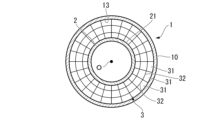
以下、本開示の第一実施形態に係るヒートパイプ100について、図1から図3を参照して説明する。ヒートパイプ100は、一定の方向に熱を輸送するための装置である。図1に示すように、ヒートパイプ100は、外筒1と、内筒2と、ウィック3と、を備えている。
外筒1は、軸線Oに沿って延びる有底筒状をなしている。より具体的には外筒1は、軸線Oを中心とする円筒状の外筒本体10と、この外筒本体10の軸線O方向一方側の端部を閉塞する第一蓋体11と、軸線O方向他方側の端部を閉塞する第二蓋体12と、を有している。
内筒2は、外筒1の内側に設けられ、軸線Oに沿って延びる円筒状をなしている。内筒2は外筒1と同軸上に設けられることが望ましい。軸線O方向における内筒2の寸法は、外筒1の寸法よりも小さく設定されている。詳細には、内筒2の軸線O方向一方側の端部は、外筒1の軸線O方向一方側の端部よりも他方側に位置している。また、内筒2の軸線O方向他方側の端部は、外筒1の軸線O方向他方側の端部よりも一方側に位置している。これにより、内筒2の軸線O方向両端部には、軸線Oに対する径方向に広がる開口部2aが形成されている。なお、開口部2aは内筒2の周方向全域にわたって形成されていてもよいし、周方向の一部の領域のみに形成されていてもよい。
ウィック3は、外筒1と内筒2との間に設けられている。より詳細には、外筒1の内周面13、及び内筒2の外周面21との間にウィック3が充填されている。これら外筒1、内筒2、及びウィック3は、例えばAM造形法(Additive Modeling造形法)を含む3D積層造形によって互いに同一の材料で一体に形成されている。なお、ウィック3のみを押し出し成型によって形成することも可能である。
ヒートパイプ100を動作させるに当たっては、まずヒートパイプ100内に作動流体としての水やアルコールを充填する。その後、軸線O方向一方側の端部に熱源を近接させ、他方側の端部に低温熱源(又は冷却媒体)を近接させる。
続いて、本開示の第二実施形態に係るヒートパイプ100bについて、図4と図5を参照して説明する。なお、上記第一実施形態と同様の構成については同一の符号を付し、詳細な説明を省略する。図4又は図5に示すように、本実施形態に係るヒートパイプ100bは、フィン4をさらに備えている。
次に、本開示の第三実施形態に係るヒートパイプ100cについて、図7を参照して説明する。なお、上記の各実施形態と同様の構成については同一の符号を付し、詳細な説明を省略する。図7に示すように、本実施形態に係るヒートパイプ100cは、親水部5と、疎水部6と、をさらに備えている。
続いて、本開示の第四実施形態に係るヒートパイプ100dについて、図8と図9を参照して説明する。なお、上記の各実施形態と同様の構成については同一の符号を付し、詳細な説明を省略する。図8及び図9に示すように、本実施形態に係るヒートパイプ100dは、外筒1と、ウィック7と、を備えている。外筒1は、第一実施形態で説明したものと同様に、外筒本体10、第一蓋体11、及び第二蓋体12を有している。
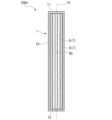
図10に示すように、上述したヒートパイプ100、100b、100c、100d、又はウィック3、7を、ダイキャスト用金型300の冷却に用いることが可能である。このダイキャスト用金型300は、金型本体200と、ウィック30と、蒸気流路40と、冷却部50と、を備えている。金型本体200の内部には溶融した金属材料等(ワーク90)が充填される。金型本体200の外周側には、当該金型本体200を囲むようにして複数のウィック30が間隔をあけて複数配列されている。また、これらウィック30同士の間の空間は蒸気流路40とされている。ウィック30と蒸気流路40は冷却部50に接している。つまり、この例では、ウィック30と蒸気流路40によって上述したヒートパイプ100、100b、100c、100dが形成されている。金型本体200は熱源に相当し、冷却部50は低温熱源に相当する。このような構成を採ることによって、金型本体200をより早くかつ安定的に冷却することが可能となる。
各実施形態に記載のヒートパイプ100は、例えば以下のように把握される。
1 外筒
2 内筒
2a 開口部
3 ウィック
4 フィン
5 親水部
6 疎水部
7 ウィック
8 気液通過部
8a 気体通過流路
9 液通過部
10 外筒本体
10a 薄肉部
11 第一蓋体
12 第二蓋体
13 内周面
21 外周面
30 ウィック
31 微小貫通部
32 連通部
40 蒸気流路
50 冷却部
200 金型本体
300 ダイキャスト用金型
Claims (8)
- 軸線方向に延びる外筒と、
該外筒の内側で前記軸線方向に延びるように設けられた内筒と、
前記外筒と前記内筒との間に設けられており、前記軸線方向に直線状に延びる微小貫通部が複数形成されたウィックと、
を備え、
前記軸線方向における前記外筒の少なくとも一方の端部を含む部分には、他の部分よりも肉厚が小さい薄肉部が形成され、
該薄肉部には、前記軸線に対する径方向に突出するとともに周方向に間隔をあけて配列された複数のフィンが設けられ、
前記フィンは、前記内筒と前記外筒とを径方向に接続しているヒートパイプ。 - 前記ウィックは、三次元格子状をなすことで、互いに隣接する前記微小貫通部同士を連通させる連通部を有する請求項1に記載のヒートパイプ。
- 前記微小貫通部は、前記外筒と前記内筒との間で前記軸線に対する径方向に複数設けられている請求項1又は2に記載のヒートパイプ。
- 前記フィンの表面粗さは、前記外筒の内周面の表面粗さよりも大きく設定されている請求項1から3のいずれか一項に記載のヒートパイプ。
- 前記外筒の内周面、及び前記内筒の外周面における前記軸線方向の一方側の端部を含む領域に設けられ、他の部分よりも相対的に高い親水性を有する親水部と、
前記外筒の内周面、及び前記内筒の外周面における前記軸線方向の他方側の端部を含む領域に設けられ、他の部分よりも相対的に高い疎水性を有する疎水部と、
をさらに有する請求項1から4のいずれか一項に記載のヒートパイプ。 - 軸線方向に延びる外筒と、
前記外筒内で該外筒の内周面に、同一の材料によって前記外筒と一体に形成され、内周側に前記軸線に沿って貫通する気体通過流路を形成するウィックと、
を備え、
前記ウィックは、前記軸線の径方向外側から内側に向かうに従って空隙率が大きくなる気液通過部を有し、
前記ウィックは、前記気液通過部の外周側に設けられ、前記気液通過部よりも低い空隙率を有する液通過部をさらに有するヒートパイプ。 - 前記ウィックは、三次元格子状をなすことで、互いに隣接する前記気液通過部同士、及び互いに隣接する前記液通過部同士を連通させる連通部を有する請求項6に記載のヒートパイプ。
- 前記外筒の内周面における前記軸線方向の一方側の端部を含む領域に設けられ、他の部分よりも相対的に高い親水性を有する親水部と、
前記外筒の内周面における前記軸線方向の他方側の端部を含む領域に設けられ、他の部分よりも相対的に高い疎水性を有する疎水部と、
をさらに有する請求項6又は7に記載のヒートパイプ。
Priority Applications (2)
| Application Number | Priority Date | Filing Date | Title |
|---|---|---|---|
| JP2021035233A JP7550682B2 (ja) | 2021-03-05 | 2021-03-05 | ヒートパイプ |
| US17/583,538 US20220282934A1 (en) | 2021-03-05 | 2022-01-25 | Heat pipe |
Applications Claiming Priority (1)
| Application Number | Priority Date | Filing Date | Title |
|---|---|---|---|
| JP2021035233A JP7550682B2 (ja) | 2021-03-05 | 2021-03-05 | ヒートパイプ |
Publications (2)
| Publication Number | Publication Date |
|---|---|
| JP2022135436A JP2022135436A (ja) | 2022-09-15 |
| JP7550682B2 true JP7550682B2 (ja) | 2024-09-13 |
Family
ID=83116975
Family Applications (1)
| Application Number | Title | Priority Date | Filing Date |
|---|---|---|---|
| JP2021035233A Active JP7550682B2 (ja) | 2021-03-05 | 2021-03-05 | ヒートパイプ |
Country Status (2)
| Country | Link |
|---|---|
| US (1) | US20220282934A1 (ja) |
| JP (1) | JP7550682B2 (ja) |
Families Citing this family (2)
| Publication number | Priority date | Publication date | Assignee | Title |
|---|---|---|---|---|
| FR3123114B1 (fr) * | 2021-05-20 | 2023-07-14 | Euro Heat Pipes | Caloduc à performance améliorée sous diverses répartitions de charges thermiques |
| US12305929B2 (en) * | 2023-02-06 | 2025-05-20 | Westinghouse Electric Company Llc | Advanced manufacturing heat pipe segment with integral printed wick |
Citations (2)
| Publication number | Priority date | Publication date | Assignee | Title |
|---|---|---|---|---|
| JP2003148887A (ja) | 2001-11-15 | 2003-05-21 | Mitsubishi Materials Corp | ヒートパイプ及びその製造方法 |
| JP2018162962A (ja) | 2017-01-05 | 2018-10-18 | ザ・ボーイング・カンパニーThe Boeing Company | 不均一な断面を有するヒートパイプ |
Family Cites Families (4)
| Publication number | Priority date | Publication date | Assignee | Title |
|---|---|---|---|---|
| TWI260385B (en) * | 2005-01-21 | 2006-08-21 | Foxconn Tech Co Ltd | Sintered heat pipe and method for manufacturing the same |
| CN100437006C (zh) * | 2005-08-12 | 2008-11-26 | 富准精密工业(深圳)有限公司 | 热管之制造方法 |
| JP4737285B2 (ja) * | 2008-12-24 | 2011-07-27 | ソニー株式会社 | 熱輸送デバイス及び電子機器 |
| KR20150077689A (ko) * | 2013-12-30 | 2015-07-08 | 포항공과대학교 산학협력단 | 친수성 및 소수성 표면으로 처리한 히트파이프 |
-
2021
- 2021-03-05 JP JP2021035233A patent/JP7550682B2/ja active Active
-
2022
- 2022-01-25 US US17/583,538 patent/US20220282934A1/en not_active Abandoned
Patent Citations (2)
| Publication number | Priority date | Publication date | Assignee | Title |
|---|---|---|---|---|
| JP2003148887A (ja) | 2001-11-15 | 2003-05-21 | Mitsubishi Materials Corp | ヒートパイプ及びその製造方法 |
| JP2018162962A (ja) | 2017-01-05 | 2018-10-18 | ザ・ボーイング・カンパニーThe Boeing Company | 不均一な断面を有するヒートパイプ |
Non-Patent Citations (1)
| Title |
|---|
| B. Richard, D. Pellicone, B. Anderson,Loop Heat Pipe Wick Fabrication via Additive Manufacturing,48th International Conference on Environmental Systems,米国,2018年07月08日,http://hdl.handle.net/2346/74027 |
Also Published As
| Publication number | Publication date |
|---|---|
| US20220282934A1 (en) | 2022-09-08 |
| JP2022135436A (ja) | 2022-09-15 |
Similar Documents
| Publication | Publication Date | Title |
|---|---|---|
| JP7550682B2 (ja) | ヒートパイプ | |
| JP5528419B2 (ja) | 押出で製造される薄膜型ヒートパイプ | |
| TWI426859B (zh) | 散熱模組、均溫元件及均溫元件之製造方法 | |
| JP2013517448A (ja) | 熱交換器、熱交換器を含む生ごみ処理機、及び熱交換器の製造方法 | |
| CN109964093B (zh) | 热管 | |
| JP2019184219A (ja) | 液体弾管路を有する還流ヒートパイプ | |
| CN101738119B (zh) | 热管嵌合槽道吸液芯 | |
| TW201408979A (zh) | 熱管及其製造方法 | |
| KR101097390B1 (ko) | 이중관 구조의 히트파이프 | |
| TWI680274B (zh) | 複合式熱管 | |
| JP3175221U (ja) | ヒートパイプ構造 | |
| US20130306275A1 (en) | Heat dissipation structure for heat dissipation device | |
| JP2023152616A (ja) | ヒートパイプ、熱交換装置、及び、ヒートパイプの製造方法 | |
| JP2019190812A (ja) | 同じ管路が気流流路および液流流路に仕切られた還流ヒートパイプ | |
| CN103185476B (zh) | 散热单元之散热结构 | |
| JP7179170B2 (ja) | 自励振動ヒートパイプ冷却装置および当該冷却装置を搭載した鉄道車両 | |
| JP4810997B2 (ja) | ヒートパイプ及びその製造方法 | |
| CN209588785U (zh) | 复合式热管 | |
| WO2017082127A1 (ja) | 電子機器の冷却装置 | |
| US11662155B2 (en) | Pulse loop heat exchanger and manufacturing method of the same | |
| WO2019163973A1 (ja) | 熱交換器のタンク構造 | |
| JP2013120053A (ja) | ヒートパイプ | |
| JP3173464U (ja) | ヒートパイプの構造 | |
| CN103075905B (zh) | 热管结构 | |
| TWI614477B (zh) | 星形熱管結構 |
Legal Events
| Date | Code | Title | Description |
|---|---|---|---|
| A621 | Written request for application examination |
Free format text: JAPANESE INTERMEDIATE CODE: A621 Effective date: 20230627 |
|
| A977 | Report on retrieval |
Free format text: JAPANESE INTERMEDIATE CODE: A971007 Effective date: 20240207 |
|
| A131 | Notification of reasons for refusal |
Free format text: JAPANESE INTERMEDIATE CODE: A131 Effective date: 20240305 |
|
| A521 | Request for written amendment filed |
Free format text: JAPANESE INTERMEDIATE CODE: A523 Effective date: 20240502 |
|
| TRDD | Decision of grant or rejection written | ||
| A01 | Written decision to grant a patent or to grant a registration (utility model) |
Free format text: JAPANESE INTERMEDIATE CODE: A01 Effective date: 20240806 |
|
| A61 | First payment of annual fees (during grant procedure) |
Free format text: JAPANESE INTERMEDIATE CODE: A61 Effective date: 20240903 |
|
| R150 | Certificate of patent or registration of utility model |
Ref document number: 7550682 Country of ref document: JP Free format text: JAPANESE INTERMEDIATE CODE: R150 |