EP4092195A1 - Mastelement, insbesondere mäklerelement, für eine baumaschine und verfahren zur herstellung des mastelementes - Google Patents
Mastelement, insbesondere mäklerelement, für eine baumaschine und verfahren zur herstellung des mastelementes Download PDFInfo
- Publication number
- EP4092195A1 EP4092195A1 EP21174764.7A EP21174764A EP4092195A1 EP 4092195 A1 EP4092195 A1 EP 4092195A1 EP 21174764 A EP21174764 A EP 21174764A EP 4092195 A1 EP4092195 A1 EP 4092195A1
- Authority
- EP
- European Patent Office
- Prior art keywords
- mast
- profile
- reinforcement
- longitudinal direction
- along
- Prior art date
- Legal status (The legal status is an assumption and is not a legal conclusion. Google has not performed a legal analysis and makes no representation as to the accuracy of the status listed.)
- Granted
Links
Images

Classifications
-
- E—FIXED CONSTRUCTIONS
- E21—EARTH OR ROCK DRILLING; MINING
- E21B—EARTH OR ROCK DRILLING; OBTAINING OIL, GAS, WATER, SOLUBLE OR MELTABLE MATERIALS OR A SLURRY OF MINERALS FROM WELLS
- E21B7/00—Special methods or apparatus for drilling
- E21B7/02—Drilling rigs characterised by means for land transport with their own drive, e.g. skid mounting or wheel mounting
- E21B7/023—Drilling rigs characterised by means for land transport with their own drive, e.g. skid mounting or wheel mounting the mast being foldable or telescopically retractable
-
- E—FIXED CONSTRUCTIONS
- E02—HYDRAULIC ENGINEERING; FOUNDATIONS; SOIL SHIFTING
- E02D—FOUNDATIONS; EXCAVATIONS; EMBANKMENTS; UNDERGROUND OR UNDERWATER STRUCTURES
- E02D7/00—Methods or apparatus for placing sheet pile bulkheads, piles, mouldpipes, or other moulds
- E02D7/02—Placing by driving
- E02D7/06—Power-driven drivers
- E02D7/14—Components for drivers inasmuch as not specially for a specific driver construction
- E02D7/16—Scaffolds or supports for drivers
-
- E—FIXED CONSTRUCTIONS
- E02—HYDRAULIC ENGINEERING; FOUNDATIONS; SOIL SHIFTING
- E02D—FOUNDATIONS; EXCAVATIONS; EMBANKMENTS; UNDERGROUND OR UNDERWATER STRUCTURES
- E02D7/00—Methods or apparatus for placing sheet pile bulkheads, piles, mouldpipes, or other moulds
- E02D7/02—Placing by driving
- E02D7/06—Power-driven drivers
- E02D7/14—Components for drivers inasmuch as not specially for a specific driver construction
- E02D7/16—Scaffolds or supports for drivers
- E02D7/165—Scaffolds or supports for drivers of variable length, e.g. foldable or telescopic
-
- E—FIXED CONSTRUCTIONS
- E21—EARTH OR ROCK DRILLING; MINING
- E21B—EARTH OR ROCK DRILLING; OBTAINING OIL, GAS, WATER, SOLUBLE OR MELTABLE MATERIALS OR A SLURRY OF MINERALS FROM WELLS
- E21B15/00—Supports for the drilling machine, e.g. derricks or masts
- E21B15/003—Supports for the drilling machine, e.g. derricks or masts adapted to be moved on their substructure, e.g. with skidding means; adapted to drill a plurality of wells
Definitions
- the invention relates to a mast element, in particular a leader element, for a construction machine, with an elongate, hollow mast profile, which is approximately rectangular in cross section and has a linear guide for a mast carriage on its outside along a longitudinal direction of the mast, according to the preamble of claim 1.
- the invention further relates to a method for manufacturing a mast element according to claim 12.
- Mast elements of this type are known in particular as masts for earth boring devices, which are used, for example, to create foundation piles. Such mast elements, which are essentially vertically aligned during operation, typically have a length of a few meters up to approx. 30 meters.
- a linear guide for a mast or working carriage is provided along a front side of the mast element, which is frequently also referred to as leader.
- a drilling drive for an earth drilling device can be arranged on this working carriage, for example.
- the mast elements must have a high degree of rigidity with the lowest possible weight, on the one hand to ensure reliable guidance and on the other hand to keep the center of gravity of the entire device low for good tipping stability. It is known to have an approximately rectangular hollow profile for such mast elements use. Such a tubular hollow profile can be made of a steel material as a seamless hollow profile or a U-profile. In order to stiffen such mast profiles, it is known to divide the mast profile into segments of a few meters in length and to weld in a transversely directed stiffening plate, which is also referred to as a mast bulkhead, between the segments. A U-profile can be closed by welding on a cover plate.
- a further stiffening of such a mast element can be achieved by additionally welding elongate guide rails to the outside. These are used to form the mast longitudinal guide for a mast carriage and at the same time they form an additional stiffening element on the outside.
- a mast element with an elongate tubular body is known, which is formed from a fiber composite material.
- the processing of fiber composite materials is time-consuming and expensive.
- a connection to steel materials is difficult and requires special types of connection.
- the invention is based on the object of specifying a mast element and a method for production with which a particularly high degree of rigidity can be achieved with efficient and cost-effective manufacturability.
- the object is achieved by a mast element having the features of claim 1 and a method having the features of claim 12 .
- Preferred embodiments of the invention are given in the dependent claims.
- the mast element according to the invention is characterized in that within the mast profile along the longitudinal direction of the mast at least one diagonal Extends reinforcing element, which is arranged at an oblique angle to the sides of the approximately rectangular mast profile.
- a basic idea of the invention can be seen in providing a reinforcement element within the hollow mast profile, which for reinforcement purposes extends diagonally to the sides of the mast profile, ie at an oblique angle to the inner sides of the approximately rectangular profile.
- the oblique angle deviates from a right angle.
- the reinforcement element runs in the longitudinal direction of the mast at least over one or more partial areas, preferably over the entire length of the mast element.
- the reinforcement element can be connected to the outer mast profile in any suitable manner, for example screwed.
- a preferred embodiment of the invention is that the at least one reinforcement element is welded along an inside of the mast profile. Welding represents a reliable and cost-effective connection between metal materials. The weld seam runs along the longitudinal direction of the mast.
- the at least one reinforcement element is welded along at least two side edges to preferably opposite walls of the mast profile.
- the diagonal reinforcement element which can also be referred to as a stiffening element, can preferably extend diagonally through the mast hollow profile from one corner area to an opposite corner area.
- two or more reinforcement elements can also be provided within the mast profile.
- a plurality of reinforcing elements can also be arranged, for example in a V, X or Y arrangement.
- a particularly efficient reinforcement can be achieved in that the at least one reinforcement element has a plate-shaped metal sheet or a folded sheet metal.
- Such reinforcement elements can be manufactured inexpensively.
- a folded metal sheet which can have an L-shape, a C-shape or a Z-shape in cross section, achieves an additional increase in the torsional rigidity compared to a flat sheet metal plate.
- a particularly high level of reinforcement is achieved in particular in that several reinforcement elements are firmly attached, in particular welded, along the inside of the mast.
- the multiple reinforcement elements can be offset in the longitudinal direction of the axis or arranged and welded directly next to one another within the mast profile.
- the reinforcement elements can also be welded to one another at their butt joints.
- the reinforcement element can be a continuous plate element.
- the at least one reinforcement element has recesses to reduce weight. These recesses can be notches in the shape of a circular disk in the central areas of the plate-shaped reinforcement element. As a result, a noticeable weight reduction of the reinforcement element can be achieved with continued good rigidity.
- the mast profile is formed by connecting at least two elongate mast parts, with connecting joints of the mast parts running in the longitudinal direction of the mast.
- a stiffening element can first be welded to a first mast part with an L-shaped or C-shaped cross section along the longitudinal direction of the mast.
- a second longitudinal mast part can then be welded to the first mast part along the longitudinal direction of the mast in order to close the mast hollow profile, so that the reinforced mast hollow profile can be formed efficiently overall.
- Continuous welds or spot welds can be provided.
- screw connections and/or tongue and groove connections can be provided.
- the at least one reinforcement element is welded to at least one elongate mast part before the hollow mast profile is closed on the peripheral side by welding on the last elongate mast part. This allows particularly simple manufacturability, with the weld seams also being able to be produced by welding robots.
- the mast element according to the invention can be used or attached to a wide variety of devices and systems on its own or in combination with other mast elements.
- the invention includes a construction machine, in particular a civil engineering machine, with a carrier device and a mast attached thereto, the mast having at least one mast element according to the invention.
- a particularly stiff mast is required for construction machines with mobile carrier devices in particular, while at the same time the overall center of gravity of the construction machine must not be shifted too far up through the mast in order to ensure sufficient stability and security of the construction machine against tipping. This can be achieved particularly well with the mast element according to the invention.
- the mast is particularly advantageous for the mast to be designed as a leader, in particular a telescopic leader.
- a leader basically represents a vertical mast with at least one linear guide, in particular for a working carriage.
- a second mast element is linearly displaceably guided along the linear guide of a first mast element.
- a linear guide for the working slide can also be arranged on the second mast element.
- the invention also includes a method for producing a mast element according to the invention, wherein during or after the formation of the hollow mast profile in a mast longitudinal direction within the mast profile the at least one diagonal reinforcement element is attached.
- the mast profile is particularly preferably composed of two or more elongate mast parts, each of which extends over the length of the mast element, in particular welded together.
- the mast elements can be elongated Sheet metal plates or sheet metal profiles.
- the at least one reinforcement element is inserted and preferably welded in the longitudinal direction on the inner sides of the still open mast profile. This can be done easily and efficiently.
- the mast profile can then be attached, in particular welded, on the other side to form the closed, hollow mast profile.
- the figure 1 shows a schematic cross-sectional view through a mast element 10 according to the invention, which is essentially formed by an outer hollow mast profile 12 .
- the mast profile 12 can be assembled and welded from different mast parts or walls, which run in a longitudinal direction of the mast.
- the longitudinal direction of the mast extends perpendicularly to the plane of the drawing.
- the mast profile 12 has a front wall 14, two side walls 16 and a rear wall 18 as mast parts, which are welded together to form the mast profile 12, which is rectangular in cross section.
- two laterally projecting, high guide profiles 22 are inserted and welded, which form a linear guide 20 along the front wall 14 for a mast or working carriage, not shown.
- first reinforcement element 30 and a second reinforcement element 40 are arranged inside the hollow mast profile 12 and welded to the inner sides of the outer mast profile 12.
- the diagonal first reinforcement element 30 is an isosceles metal sheet which is bent at an approximately right angle and which is welded at its free ends to the respective opposite guide profiles 22 .
- the legs of the folded first Reinforcing element 30 are arranged at an angle of about 45 ° to the side walls 16, with an edge area is approximately in the middle of the mast profile 12.
- the diagonal second reinforcement element 40 is fastened to the left side wall 16 in a corner area on the one hand and welded to the first reinforcement element 30 in the edge area approximately in the middle of the mast profile 12 on the other hand.
- a particularly high rigidity of the hollow mast profile 12 and thus of the mast element 10 is achieved by this multiple diagonal stiffening running in the longitudinal direction of the mast.
- the reinforcing elements 30, 40 forming the individual chambers in the mast profile 12 can also be referred to as longitudinal mast bulkheads.
- An X-arrangement can also be provided for higher amplification.
- additional longitudinal profiles can be welded parallel or at right angles to the inner sides on the inside of the individual mast parts for reinforcement, such as a first longitudinal profile 24 on the inside of the front wall 14 and a second longitudinal profile 26 on an inside of the rear wall 18, which u. increase the dent resistance of the front 14 and rear 18 walls.
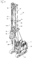
- the carrier device 71 comprises an upper carriage 72 which is rotatably mounted on an undercarriage 73 which has a crawler chassis.
- a substantially vertically directed mast 74 is mounted on the superstructure 72 and comprises a mast element 10 according to the invention.
- a linear guide 20 for a mast slide 75 is formed along the mast 74 with the mast element 10 .
- a rotary drive 76 can be mounted on the mast carriage 75 .
- a Kelly bar arrangement 100 which protrudes downwards through the annular rotary drive 76 can be suspended via a support cable 80 which is guided over a mast head of the mast 74 .
- a drilling tool (not shown), for example a box drill, can be attached to a tool connection 98 at a lower end of the Kelly bar arrangement 100 .
- At least one supply line 82 can be used, for example, to supply hydraulic fluid from the carrier device 71 via a suspension device 96 to the Kelly bar arrangement 100 and thus to an attached drilling tool.
- access holes 77 are indicated along the mast 74, which were absolutely necessary in the prior art for welding on transversely directed bulkhead plates, but can be omitted in a mast element 10 according to the invention.
Landscapes
- Engineering & Computer Science (AREA)
- Mining & Mineral Resources (AREA)
- Life Sciences & Earth Sciences (AREA)
- Geology (AREA)
- General Life Sciences & Earth Sciences (AREA)
- Environmental & Geological Engineering (AREA)
- Fluid Mechanics (AREA)
- Physics & Mathematics (AREA)
- Geochemistry & Mineralogy (AREA)
- Paleontology (AREA)
- Civil Engineering (AREA)
- General Engineering & Computer Science (AREA)
- Structural Engineering (AREA)
- Mechanical Engineering (AREA)
- Earth Drilling (AREA)
- Forklifts And Lifting Vehicles (AREA)
Abstract
Description
- Die Erfindung betrifft ein Mastelement, insbesondere ein Mäklerelement, für eine Baumaschine, mit einem länglichen hohlen Mastprofil, welches im Querschnitt etwa rechteckig ist und an seiner Außenseite entlang einer Mastlängsrichtung eine Linearführung für einen Mastschlitten aufweist, gemäß dem Oberbegriff des Anspruchs 1.
- Die Erfindung betrifft weiter ein Verfahren zum Herstellen eines Mastelementes gemäß dem Anspruch 12.
- Derartige Mastelemente sind insbesondere als Masten bei Erdbohrgeräten bekannt, welche beispielsweise zur Erstellung von Gründungspfählen eingesetzt werden. Derartige Mastelemente, welche im Betrieb im Wesentlichen vertikal ausgerichtet sind, weisen typischerweise eine Länge von einigen Metern bis zu ca. 30 Metern auf. Entlang einer Vorderseite des Mastelementes, welches häufig auch als Mäkler bezeichnet wird, ist eine Linearführung für einen Mast- oder Arbeitsschlitten vorgesehen. An diesem Arbeitsschlitten kann beispielsweise ein Bohrantrieb für ein Erdbohrgerät angeordnet sein.
- Die Mastelemente müssen eine hohe Steifigkeit bei einem möglichst geringen Gewicht aufweisen, um einerseits eine zuverlässige Führung zu gewährleisten und andererseits einen Schwerpunkt des Gesamtgerätes für eine gute Kippstabilität niedrig zu halten. Es ist bekannt, für derartige Mastelemente ein etwa rechteckiges Hohlprofil zu verwenden. Ein solches rohrförmiges Hohlprofil kann als ein nahtloses Hohlprofil oder ein U-Profil aus einem Stahlwerkstoff gefertigt sein. Zur Versteifung derartiger Mastprofile ist es bekannt, das Mastprofil in Segmente von einigen Metern Länge zu unterteilen und zwischen den Segmenten eine quer gerichtete Versteifungsplatte, welche auch als ein Mastschott bezeichnet wird, einzuschweißen. Ein U-Profil kann durch Aufschweißen einer Deckplatte geschlossen werden.
- Für ein Aufbringen nicht nur einer Außenschweißnaht, sondern auch einer Innennaht ist es bei derartigen Schottplatten erforderlich, in das Mastprofil Zugangslöcher, sogenannte Handlöcher, im Bereich des Schottes einzubringen, so dass ein Schweißer hierdurch an der Innenseite des Masthohlprofiles eine Verschweißung zwischen dem Masthohlprofil und der Schottplatte ausführen kann. Dies ist kompliziert und sehr zeit- und arbeitsaufwändig. Ein Verschweißen der Schottplatten kann auch entfallen, was sich jedoch nachteilig auf die Steifigkeit des Mastes auswirkt.
- Eine weitere Versteifung eines solchen Mastelementes kann dadurch erreicht werden, dass zusätzlich an der Außenseite längliche Führungsleisten angeschweißt werden. Diese dienen zum Bilden der Mastlängsführung für einen Mastschlitten und gleichzeitig bilden diese ein zusätzliches Versteifungselement an der Außenseite.
- Aus der
EP 2 520 756 B1 ist ein Mastelement mit einem länglichen Rohrkörper bekannt, welcher aus einem Faserverbundwerkstoff gebildet ist. Das Verarbeiten von Faserverbundwerkstoffen ist zeit- und kostenaufwändig. Eine Verbindung zu Stahlwerkstoffen ist schwierig und bedarf spezieller Verbindungsarten. - Der Erfindung liegt die Aufgabe zugrunde, ein Mastelement und ein Verfahren zur Herstellung anzugeben, mit welchen bei einer effizienten und kostengünstigen Herstellbarkeit eine besonders hohe Steifigkeit erreicht werden kann.
- Die Aufgabe wird nach der Erfindung durch ein Mastelement mit den Merkmalen des Anspruchs 1 und ein Verfahren mit den Merkmalen des Anspruchs 12 gelöst. Bevorzugte Ausführungsformen der Erfindung sind in den abhängigen Ansprüchen angegeben.
- Das erfindungsgemäße Mastelement ist dadurch gekennzeichnet, dass sich innerhalb des Mastprofils entlang der Mastlängsrichtung mindestens ein diagonales Verstärkungselement erstreckt, welches in einem schrägen Winkel zu Seiten des etwa rechteckigen Mastprofils angeordnet ist.
- Eine Grundidee der Erfindung kann darin gesehen werden, innerhalb des hohlen Mastprofils ein Verstärkungselement vorzusehen, welches sich zur Versteifung diagonal zu den Seiten des Mastprofils, also in einem schrägen Winkel zu den Innenseiten des etwa rechteckigen Profils erstreckt. Der schräge Winkel weicht von einem rechten Winkel ab. Das Verstärkungselement verläuft in Mastlängsrichtung zumindest über einen oder mehrere Teilbereiche, vorzugsweise über die gesamte Länge des Mastelementes. Durch eine solche innere diagonale Versteifung kann eine erhebliche Steigerung der Steifigkeit des Mastprofils in Bezug auf Biegung quer zur Längsrichtung und die Torsionssteifigkeit bei einem relativ geringen zusätzlichen Gewicht erreicht werden. Die Eckbereiche des Mastprofils können gerundet oder mit Schrägungsflächen versehen sein. Bei gleicher Seitenlänge kann das Rechteckprofil auch etwa quadratisch sein.
- Grundsätzlich kann das Verstärkungselement in jeder geeigneten Weise mit dem äußeren Mastprofil verbunden, etwa verschraubt werden. Eine bevorzugte Ausführungsform der Erfindung besteht darin, dass das mindestens eine Verstärkungselement entlang einer Innenseite des Mastprofils verschweißt ist. Ein Verschweißen stellt eine zuverlässige und kostengünstige Verbindung zwischen Metallwerkstoffen dar. Die Schweißnaht verläuft dabei entlang der Mastlängsrichtung.
- Besonders vorteilhaft ist es nach einer Weiterbildung der Erfindung, dass das mindestens eine Verstärkungselement entlang von mindestens zwei Seitenkanten an vorzugsweise gegenüberliegenden Wänden des Mastprofils verschweißt ist. Das diagonale Verstärkungselement, welches auch als Versteifungselement bezeichnet werden kann, kann sich vorzugsweise von einem Eckbereich zu einem gegenüberliegenden Eckbereich diagonal durch das Masthohlprofil erstrecken. Grundsätzlich können auch zwei oder mehr Verstärkungselemente innerhalb des Mastprofils vorgesehen sein. Es können auch mehrere Verstärkungselemente angeordnet sein, etwa in einer V-, X- oder Y-Anordnung.
- Eine besonders effiziente Versteifung kann nach einer weiteren Ausführungsvariante der Erfindung dadurch erzielt werden, dass das mindestens eine Verstärkungselement ein plattenförmiges Blech oder ein abgekantetes Blech aufweist. Derartige Verstärkungselemente können kostengünstig hergestellt werden. Durch ein abgekantetes Blech, welches im Querschnitt eine L-Form, eine C-Form oder eine Z-Form aufweisen kann, wird eine zusätzliche Erhöhung der Verwindungssteifigkeit gegenüber eine ebenen Blechplatte erzielt.
- Eine besonders hohe Versteifung wird nach einer Weiterbildung der Erfindung insbesondere dadurch erreicht, dass mehrere Verstärkungselemente entlang der Mastinnenseite fest angebracht, insbesondere verschweißt sind. Die mehreren Verstärkungselemente können sowohl in Achslängsrichtung versetzt als auch unmittelbar nebeneinander innerhalb des Mastprofils angeordnet und verschweißt sein. Dabei können die Verstärkungselemente an ihren Stoßfugen ebenfalls miteinander verschweißt sein.
- Grundsätzlich kann das Verstärkungselement ein durchgehendes Plattenelement sein. Eine besonders bevorzugte Ausführungsform der Erfindung besteht darin, dass das mindestens eine Verstärkungselement zur Gewichtsreduzierung Ausnehmungen aufweist. Diese Ausnehmungen können etwa kreisscheibenförmige Ausklinkungen in Mittenbereichen des plattenförmigen Verstärkungselementes sein. Hierdurch kann eine merkliche Gewichtsreduzierung des Verstärkungselementes bei einer weiter guten Steifigkeit erreicht werden.
- Für eine gute Herstellbarkeit des Mastelementes ist es nach einer Weiterbildung der Erfindung vorteilhaft, dass das Mastprofil durch Verbinden aus mindestens zwei länglichen Mastteilen gebildet ist, wobei Verbindungsfugen der Mastteile in Mastlängsrichtung verlaufen. So kann beispielsweise ein Versteifungselement zunächst an ein im Querschnitt L-förmiges oder C-förmiges erstes Mastteil entlang der Mastlängsrichtung verschweißt werden. Anschließend kann ein zweites Mastlängsteil zum Schließen des Masthohlprofils an das erste Mastteil entlang der Mastlängsrichtung angeschweißt werden, so dass insgesamt das versteifte Masthohlprofil effizient gebildet werden kann. Es können durchgehende Schweißnähte oder Punktschweißverbindungen vorgesehen werden. Alternativ oder ergänzend können Schraubverbindungen und/oder Nut-Feder-Verbindungen vorgesehen sein.
- Insbesondere ist es vorteilhaft, dass das mindestens eine Verstärkungselement an mindestens einem länglichen Mastteil angeschweißt ist, bevor das hohle Mastprofil durch Anschweißen des letzten länglichen Mastteiles umfangsseitig geschlossen ist. Dies erlaubt eine besonders einfache Herstellbarkeit, wobei die Schweißnähte auch durch Schweißroboter erzeugbar sind.
- Grundsätzlich kann das erfindungsgemäße Mastelement allein oder in Kombination mit weiteren Mastelementen an verschiedensten Geräten und Anlagen eingesetzt oder angebaut werden. Insbesondere umfasst die Erfindung eine Baumaschine, insbesondere eine Tiefbaumaschine, mit einem Trägergerät und einem daran angebrachten Mast, wobei der Mast mindestens ein erfindungsgemäßes Mastelement aufweist.
- Insbesondere bei Baumaschinen mit mobilen Trägergeräten wird ein besonders steifer Mast benötigt, wobei gleichzeitig durch den Mast der Gesamtschwerpunkt der Baumaschine nicht zu weit nach oben verlegt sein darf, um eine ausreichende Stabilität und Kippsicherheit der Baumaschine zu gewährleisten. Dies kann mit dem erfindungsgemäßen Mastelement besonders gut erzielt werden.
- Besonders vorteilhaft ist es nach einer Weiterbildung, dass der Mast als ein Mäkler, insbesondere ein Teleskopmäkler, ausgebildet ist. Ein Mäkler stellt dabei grundsätzlich einen vertikalen Mast mit mindestens einer Linearführung, insbesondere für einen Arbeitsschlitten, dar. Bei einem Teleskopmäkler ist entlang der Linearführung eines ersten Mastelementes ein zweites Mastelement linear verschiebbar geführt. An dem zweiten Mastelement kann ebenfalls eine Linearführung für den Arbeitsschlitten angeordnet sein. Durch einen so gebildeten Teleskopmäkler können die beiden Mastelemente teleskopartig zueinander verfahren werden, so dass im Betrieb ein relativ hoher Gesamtmast erreicht werden kann.
- Die Erfindung umfasst weiterhin ein Verfahren zum Herstellen eines erfindungsgemäßen Mastelementes, wobei beim oder nach dem Bilden des hohlen Mastprofils in einer Mastlängsrichtung innerhalb des Mastprofils das mindestens eine diagonal Verstärkungselement angebracht ist.
- Besonders bevorzugt wird das Mastprofil aus zwei oder mehr länglichen Mastteilen, welche sich jeweils über die Länge des Mastelementes erstrecken, zusammengesetzt, insbesondere zusammengeschweißt. Die Mastelemente können dabei längliche Blechplatten oder Blechprofile sein. Zumindest vor dem Verschweißen des letzten Mastteiles zum Umschließen des Masthohlprofils wird das mindestens eine Verstärkungselement eingesetzt und vorzugsweise an den Innenseiten des noch offenen Mastprofils in Längsrichtung verschweißt. Dies kann einfach und effizient ausgeführt werden. Anschließend kann das Mastprofil umseitig zum Bilden des geschlossenen hohlen Mastprofils angebracht, insbesondere angeschweißt werden.
- Die Erfindung wird nachfolgend anhand von bevorzugten Ausführungsbeispielen weiter beschrieben, welche in den Zeichnungen dargestellt sind. In den Zeichnungen zeigen:
- Fig. 1
- eine schematische Querschnittsansicht durch ein erfindungsgemäßes Mastelement; und
- Fig. 2
- eine perspektivische Ansicht einer erfindungsgemäßen Baumaschine.
- Die
Figur 1 zeigt eine schematische Querschnittsansicht durch ein erfindungsgemäßes Mastelement 10, welches im Wesentlichen durch ein äußeres hohles Mastprofil 12 gebildet ist. Das Mastprofil 12 kann aus verschiedenen Mastteilen oder Wänden zusammengesetzt und geschweißt sein, welche in einer Mastlängsrichtung verlaufen. Die Mastlängsrichtung erstreckt sich senkrecht zur Zeichnungsebene. - Das Mastprofil 12 weist als Mastteile eine Vorderwand 14, zwei Seitenwände 16 und eine Rückwand 18 auf, welche zum Bilden des im Querschnitt rechteckigen Mastprofils 12 miteinander verschweißt sind. In den Eckbereichen zwischen den Seitenwänden 16 und der Vorderwand 14 sind zwei seitlich vorstehende hohe Führungsprofile 22 eingesetzt und angeschweißt, welche entlang der Vorderwand 14 eine Linearführung 20 für einen nicht-dargestellten Mast- oder Arbeitsschlitten bilden.
- Zur Versteifung des Mastelementes 10 sind im Inneren des hohlen Mastprofils 12 ein erstes Verstärkungselement 30 und ein zweites Verstärkungselement 40 angeordnet und an den Innenseiten des äußeren Mastprofils 12 verschweißt. Das diagonale erste Verstärkungselement 30 ist dabei ein etwa rechtwinklig abgekantetes gleichschenkliges Blech, welches an seinen freien Enden an den jeweils gegenüberliegenden Führungsprofilen 22 angeschweißt ist. Die Schenkel des abgekanteten ersten Verstärkungselementes 30 sind dabei etwa im Winkel von 45° zu den Seitenwänden 16 angeordnet, wobei ein Kantenbereich etwa in der Mitte des Mastprofils 12 liegt.
- Das diagonale zweite Verstärkungselement 40 ist einerseits in einem Eckbereich der linken Seitenwand 16 an dieser befestigt und andererseits etwa in der Mitte des Mastprofils 12 an dem ersten Verstärkungselement 30 im Kantenbereich angeschweißt. Durch diese in Mastlängsrichtung verlaufende mehrfache diagonale Versteifung wird eine besonders hohe Steifigkeit des hohlen Mastprofils 12 und damit des Mastelementes 10 erreicht. Die einzelne Kammern bildenden Verstärkungselemente 30, 40 in dem Mastprofil 12 können auch als Mastlängsschotte bezeichnet werden. Zur höheren Verstärkung kann auch eine X-Anordnung vorgesehen sein.
- Zusätzlich können an Innenseiten der einzelnen Mastteile zur Versteifung zusätzliche Längsprofile parallel oder rechtwinkelig zu den Innenseiten angeschweißt sein, so etwa ein erstes Längsprofil 24 an der Innenseite der Vorderwand 14 und ein zweites Längsprofil 26 an einer Innenseite der Rückwand 18, welche u. a. die Beulsteifigkeit der Vorderwand 14 und der Rückwand 18 erhöhen.
- Gemäß
Fig. 2 ist eine erfindungsgemäße Baumaschine 70 mit einem Trägergerät 71 dargestellt. Das Trägergerät 71 umfasst einen Oberwagen 72, welcher drehbar auf einem Unterwagen 73 gelagert ist, welcher ein Raupenfahrwerk aufweist. - An dem Oberwagen 72 ist ein im Wesentlichen vertikal gerichteter Mast 74 gelagert, welcher ein erfindungsgemäßes Mastelement 10 umfasst. Entlang dem Mast 74 mit dem Mastelement 10 ist eine Linearführung 20 für einen Mastschlitten 75 ausgebildet. An dem Mastschlitten 75 kann ein Drehantrieb 76 gelagert sein. Über ein Tragseil 80, welches über einen Mastkopf des Mastes 74 geführt ist, kann eine Kellystangenanordnung 100 aufgehängt sein, welche nach unten durch den ringförmigen Drehantrieb 76 hindurchragt. An einem unteren Ende der Kellystangenanordnung 100 kann an einem Werkzeuganschluss 98 ein nicht dargestelltes Bohrwerkzeug, beispielsweise ein Kastenbohrer, angebracht werden. Über mindestens eine Zuführleitung 82 kann beispielsweise Hydraulikfluid von dem Trägergerät 71 über eine Aufhängeeinrichtung 96 der Kellystangenanordnung 100 und damit einem angehängten Bohrwerkzeug zugeführt werden.
- Zur Verdeutlichung der Erfindung sind entlang des Mastes 74 Zugangslöcher 77 angedeutet, welche im Stand der Technik zwingend zum Anschweißen von quer gerichteten Schottplatten benötigt wurden, aber bei einem erfindungsgemäßen Mastelement 10 entfallen können.
Claims (12)
- Mastelement, insbesondere Mäklerelement, für eine Baumaschine, mit einem länglichen hohlen Mastprofil (12), welches im Querschnitt etwa rechteckig ist und an seiner Außenseite entlang einer Mastlängsrichtung eine Linearführung (20) für einen Mastschlitten aufweist,
dadurch gekennzeichnet,
dass innerhalb des Mastprofils (12) sich entlang der Mastlängsrichtung mindestens ein diagonales Verstärkungselement (30, 40) erstreckt, welches in einem schrägen Winkel zu Seiten des etwa rechteckigen Mastprofils (12) angeordnet ist. - Mastelement nach Anspruch 1,
dadurch gekennzeichnet,
dass das mindestens eine Verstärkungselement (30, 40) entlang einer Innenseite des Mastprofils (12) fest angebracht, insbesondere verschweißt ist. - Mastelement nach Anspruch 2,
dadurch gekennzeichnet,
dass das mindestens eine Verstärkungselement (30, 40) entlang von mindestens zwei Seitenkanten an vorzugsweise gegenüberliegenden Wänden (14, 16, 18) des Mastprofils (12) fest angebracht, insbesondere verschweißt ist. - Mastelement nach einem der Ansprüche 1 bis 3,
dadurch gekennzeichnet,
dass das mindestens eine Verstärkungselement (30, 40) ein plattenförmiges Blech oder ein abgekantetes Blech aufweist. - Mastelement nach einem der Ansprüche 1 bis 4,
dadurch gekennzeichnet,
dass mehrere Verstärkungselemente (30, 40) entlang der Innenseite des Mastprofils (12) fest angebracht, insbesondere verschweißt sind. - Mastelement nach einem der Ansprüche 1 bis 5,
dadurch gekennzeichnet,
dass das mindestens eine Verstärkungselement (30, 40) zur Gewichtsreduzierung Ausnehmungen aufweist. - Mastelement nach einem der Ansprüche 1 bis 6,
dadurch gekennzeichnet,
dass das Mastprofil (12) durch Verbinden aus mindestens zwei länglichen Mastteilen gebildet ist, wobei Verbindungsfugen der Mastteile in Mastlängsrichtung verlaufen. - Mastelement nach Anspruch 7,
dadurch gekennzeichnet,
dass die Mastteile mit ebenen und/oder abgekanteten Blechen und/oder Profilen gebildet sind. - Mastelement nach Anspruch 7 oder 8,
dadurch gekennzeichnet,
dass das mindestens eine Verstärkungselement (30, 40) an mindestens einem länglichen Mastteil angeschweißt ist, bevor das hohle Mastprofil (12) durch Anschweißen des letzten länglichen Mastteiles umfangsseitig geschlossen ist. - Baumaschine, insbesondere Tiefbaumaschine, mit einem Trägergerät und einem daran angebrachten Mast,
dadurch gekennzeichnet,
dass der Mast mindestens ein Mastelement (10) nach einem der Ansprüche 1 bis 9 aufweist. - Baumaschine nach Anspruch 10,
dadurch gekennzeichnet,
dass der Mast als ein Mäkler, insbesondere ein Teleskopmäkler, ausgebildet ist. - Verfahren zum Herstellen eines Mastelementes (10) nach einem der Ansprüche 1 bis 9;
dadurch gekennzeichnet,
dass beim oder nach dem Bilden des hohlen Mastprofils (12) in einer Mastlängsrichtung innerhalb des Mastprofils (12) das mindestens eine diagonale Verstärkungselement (30, 40) angebracht wird.
Priority Applications (4)
| Application Number | Priority Date | Filing Date | Title |
|---|---|---|---|
| EP21174764.7A EP4092195B1 (de) | 2021-05-19 | 2021-05-19 | Mastelement, insbesondere mäklerelement, für eine baumaschine und verfahren zur herstellung des mastelementes |
| PCT/EP2022/061333 WO2022243001A1 (de) | 2021-05-19 | 2022-04-28 | Mastelement, insbesondere mäklerelement, für eine baumaschine und verfahren zur herstellung des mastelementes |
| US18/556,051 US12540510B2 (en) | 2021-05-19 | 2022-04-28 | Mast element, in particular leader element, for a construction machine and method of manufacturing the mast element |
| CN202280029240.7A CN117178093A (zh) | 2021-05-19 | 2022-04-28 | 用于工程机械的桅杆元件、尤其是塔架元件以及用于制造桅杆元件的方法 |
Applications Claiming Priority (1)
| Application Number | Priority Date | Filing Date | Title |
|---|---|---|---|
| EP21174764.7A EP4092195B1 (de) | 2021-05-19 | 2021-05-19 | Mastelement, insbesondere mäklerelement, für eine baumaschine und verfahren zur herstellung des mastelementes |
Publications (3)
| Publication Number | Publication Date |
|---|---|
| EP4092195A1 true EP4092195A1 (de) | 2022-11-23 |
| EP4092195C0 EP4092195C0 (de) | 2023-07-05 |
| EP4092195B1 EP4092195B1 (de) | 2023-07-05 |
Family
ID=76325337
Family Applications (1)
| Application Number | Title | Priority Date | Filing Date |
|---|---|---|---|
| EP21174764.7A Active EP4092195B1 (de) | 2021-05-19 | 2021-05-19 | Mastelement, insbesondere mäklerelement, für eine baumaschine und verfahren zur herstellung des mastelementes |
Country Status (4)
| Country | Link |
|---|---|
| US (1) | US12540510B2 (de) |
| EP (1) | EP4092195B1 (de) |
| CN (1) | CN117178093A (de) |
| WO (1) | WO2022243001A1 (de) |
Citations (4)
| Publication number | Priority date | Publication date | Assignee | Title |
|---|---|---|---|---|
| EP0548900A2 (de) * | 1991-12-24 | 1993-06-30 | SOILMEC S.p.A. | Hydraulische Bohrmaschine mit teleskopierbarem Turm und System zum Verstauen und Hantieren von Gestänge |
| US20040188118A1 (en) * | 2003-03-26 | 2004-09-30 | Mcphee Robert | Vibratory post driving device |
| EP2520756B1 (de) | 2011-05-05 | 2013-07-17 | Klemm Bohrtechnik GmbH | Mastelement für ein Bohrgerät |
| CN111691419A (zh) * | 2020-06-23 | 2020-09-22 | 上海工程机械厂有限公司 | 一种打桩机塔架 |
Family Cites Families (5)
| Publication number | Priority date | Publication date | Assignee | Title |
|---|---|---|---|---|
| JP3589279B2 (ja) * | 1998-02-24 | 2004-11-17 | Jfeスチール株式会社 | ブレース材 |
| US9260919B2 (en) * | 2012-06-21 | 2016-02-16 | Superior Energy Services—North America Services, Inc. | Method and apparatus for aligning a BOP stack and a mast |
| CN106194980A (zh) * | 2015-05-06 | 2016-12-07 | 韦坤明 | 边加强方轴 |
| EP3440270A1 (de) * | 2016-04-08 | 2019-02-13 | Junttan OY | Führung für rammgerät, rammvorrichtung und rammgerät |
| CN206409192U (zh) * | 2016-10-25 | 2017-08-15 | 北京中车重工机械有限公司 | 旋挖钻机及其桅杆导向装置 |
-
2021
- 2021-05-19 EP EP21174764.7A patent/EP4092195B1/de active Active
-
2022
- 2022-04-28 CN CN202280029240.7A patent/CN117178093A/zh active Pending
- 2022-04-28 WO PCT/EP2022/061333 patent/WO2022243001A1/de not_active Ceased
- 2022-04-28 US US18/556,051 patent/US12540510B2/en active Active
Patent Citations (4)
| Publication number | Priority date | Publication date | Assignee | Title |
|---|---|---|---|---|
| EP0548900A2 (de) * | 1991-12-24 | 1993-06-30 | SOILMEC S.p.A. | Hydraulische Bohrmaschine mit teleskopierbarem Turm und System zum Verstauen und Hantieren von Gestänge |
| US20040188118A1 (en) * | 2003-03-26 | 2004-09-30 | Mcphee Robert | Vibratory post driving device |
| EP2520756B1 (de) | 2011-05-05 | 2013-07-17 | Klemm Bohrtechnik GmbH | Mastelement für ein Bohrgerät |
| CN111691419A (zh) * | 2020-06-23 | 2020-09-22 | 上海工程机械厂有限公司 | 一种打桩机塔架 |
Also Published As
| Publication number | Publication date |
|---|---|
| US20240209689A1 (en) | 2024-06-27 |
| EP4092195C0 (de) | 2023-07-05 |
| WO2022243001A1 (de) | 2022-11-24 |
| EP4092195B1 (de) | 2023-07-05 |
| CN117178093A (zh) | 2023-12-05 |
| US12540510B2 (en) | 2026-02-03 |
Similar Documents
| Publication | Publication Date | Title |
|---|---|---|
| DE3305740C2 (de) | ||
| DE29917734U1 (de) | Aus einem Profilelement gebildete Montageschiene | |
| EP1325861B1 (de) | Raupenfahrwerk | |
| DE102011113258B4 (de) | Teleskopschuß und Kran mit Teleskopschuß | |
| EP4092195B1 (de) | Mastelement, insbesondere mäklerelement, für eine baumaschine und verfahren zur herstellung des mastelementes | |
| EP3584370B1 (de) | Baugerät und verfahren zum betreiben eines baugerätes | |
| DE102007018183A1 (de) | Rahmenkonstruktion insbesondere für einen Omnibus | |
| DE3214625C2 (de) | Balkenförmiger Ausleger, insbesondere als Sprührahmen für Pflanzenschutzgeräte | |
| EP4092199B1 (de) | Mastelement, insbesondere mäklerelement, für eine baumaschine | |
| DE844055C (de) | Stabfoermiges Bauelement, insbesondere fuer voruebergehend benutzte Gerueste oder Vorrichtungen | |
| EP2520756B1 (de) | Mastelement für ein Bohrgerät | |
| EP3477018A1 (de) | Hohler zweipunkthebel | |
| DE8407334U1 (de) | Duebellochbohrmaschine | |
| DE2940030C2 (de) | Knotenpunkt für lösbare biegesteife Eckverbindungen von Stäben | |
| EP3168186B1 (de) | Hubmast eines flurförderzeugs | |
| DE102024115379B4 (de) | Längsteilbares Gitterstück | |
| DE1953959A1 (de) | Herzstueck mit vorzugsweise im Gesenk geschlagener Herzstueckspitze | |
| DE3820884C2 (de) | ||
| DE10015327B4 (de) | Fahrzeugkarosserie mit einer vorspannbaren Versteifungsvorrichtung | |
| DE1943686A1 (de) | Laufwagenkonstruktion fuer eine Koordinaten-Brennschneidmaschine | |
| DE102010054474B4 (de) | Kettenanschluss für ein Hubtor | |
| WO2024088973A1 (de) | Verbindungselement für eine spundwand | |
| EP0129176A2 (de) | Biegefeste Eckverbindungen | |
| DE20206970U1 (de) | Raupenfahrwerk, insbesondere für eine Baumaschine | |
| EP4212414A1 (de) | Unterwagen für eine arbeitsmaschine |
Legal Events
| Date | Code | Title | Description |
|---|---|---|---|
| STAA | Information on the status of an ep patent application or granted ep patent |
Free format text: STATUS: EXAMINATION IS IN PROGRESS |
|
| PUAI | Public reference made under article 153(3) epc to a published international application that has entered the european phase |
Free format text: ORIGINAL CODE: 0009012 |
|
| 17P | Request for examination filed |
Effective date: 20220428 |
|
| AK | Designated contracting states |
Kind code of ref document: A1 Designated state(s): AL AT BE BG CH CY CZ DE DK EE ES FI FR GB GR HR HU IE IS IT LI LT LU LV MC MK MT NL NO PL PT RO RS SE SI SK SM TR |
|
| GRAP | Despatch of communication of intention to grant a patent |
Free format text: ORIGINAL CODE: EPIDOSNIGR1 |
|
| STAA | Information on the status of an ep patent application or granted ep patent |
Free format text: STATUS: GRANT OF PATENT IS INTENDED |
|
| GRAJ | Information related to disapproval of communication of intention to grant by the applicant or resumption of examination proceedings by the epo deleted |
Free format text: ORIGINAL CODE: EPIDOSDIGR1 |
|
| STAA | Information on the status of an ep patent application or granted ep patent |
Free format text: STATUS: EXAMINATION IS IN PROGRESS |
|
| INTG | Intention to grant announced |
Effective date: 20221214 |
|
| INTC | Intention to grant announced (deleted) | ||
| GRAP | Despatch of communication of intention to grant a patent |
Free format text: ORIGINAL CODE: EPIDOSNIGR1 |
|
| STAA | Information on the status of an ep patent application or granted ep patent |
Free format text: STATUS: GRANT OF PATENT IS INTENDED |
|
| INTG | Intention to grant announced |
Effective date: 20230220 |
|
| GRAS | Grant fee paid |
Free format text: ORIGINAL CODE: EPIDOSNIGR3 |
|
| GRAA | (expected) grant |
Free format text: ORIGINAL CODE: 0009210 |
|
| STAA | Information on the status of an ep patent application or granted ep patent |
Free format text: STATUS: THE PATENT HAS BEEN GRANTED |
|
| AK | Designated contracting states |
Kind code of ref document: B1 Designated state(s): AL AT BE BG CH CY CZ DE DK EE ES FI FR GB GR HR HU IE IS IT LI LT LU LV MC MK MT NL NO PL PT RO RS SE SI SK SM TR |
|
| REG | Reference to a national code |
Ref country code: CH Ref legal event code: EP |
|
| REG | Reference to a national code |
Ref country code: AT Ref legal event code: REF Ref document number: 1584945 Country of ref document: AT Kind code of ref document: T Effective date: 20230715 |
|
| REG | Reference to a national code |
Ref country code: DE Ref legal event code: R096 Ref document number: 502021000953 Country of ref document: DE |
|
| REG | Reference to a national code |
Ref country code: IE Ref legal event code: FG4D Free format text: LANGUAGE OF EP DOCUMENT: GERMAN |
|
| U01 | Request for unitary effect filed |
Effective date: 20230725 |
|
| U07 | Unitary effect registered |
Designated state(s): AT BE BG DE DK EE FI FR IT LT LU LV MT NL PT SE SI Effective date: 20230809 |
|
| REG | Reference to a national code |
Ref country code: LT Ref legal event code: MG9D |
|
| PG25 | Lapsed in a contracting state [announced via postgrant information from national office to epo] |
Ref country code: GR Free format text: LAPSE BECAUSE OF FAILURE TO SUBMIT A TRANSLATION OF THE DESCRIPTION OR TO PAY THE FEE WITHIN THE PRESCRIBED TIME-LIMIT Effective date: 20231006 |
|
| PG25 | Lapsed in a contracting state [announced via postgrant information from national office to epo] |
Ref country code: ES Free format text: LAPSE BECAUSE OF FAILURE TO SUBMIT A TRANSLATION OF THE DESCRIPTION OR TO PAY THE FEE WITHIN THE PRESCRIBED TIME-LIMIT Effective date: 20230705 |
|
| PG25 | Lapsed in a contracting state [announced via postgrant information from national office to epo] |
Ref country code: IS Free format text: LAPSE BECAUSE OF FAILURE TO SUBMIT A TRANSLATION OF THE DESCRIPTION OR TO PAY THE FEE WITHIN THE PRESCRIBED TIME-LIMIT Effective date: 20231105 |
|
| PG25 | Lapsed in a contracting state [announced via postgrant information from national office to epo] |
Ref country code: RS Free format text: LAPSE BECAUSE OF FAILURE TO SUBMIT A TRANSLATION OF THE DESCRIPTION OR TO PAY THE FEE WITHIN THE PRESCRIBED TIME-LIMIT Effective date: 20230705 Ref country code: NO Free format text: LAPSE BECAUSE OF FAILURE TO SUBMIT A TRANSLATION OF THE DESCRIPTION OR TO PAY THE FEE WITHIN THE PRESCRIBED TIME-LIMIT Effective date: 20231005 Ref country code: IS Free format text: LAPSE BECAUSE OF FAILURE TO SUBMIT A TRANSLATION OF THE DESCRIPTION OR TO PAY THE FEE WITHIN THE PRESCRIBED TIME-LIMIT Effective date: 20231105 Ref country code: HR Free format text: LAPSE BECAUSE OF FAILURE TO SUBMIT A TRANSLATION OF THE DESCRIPTION OR TO PAY THE FEE WITHIN THE PRESCRIBED TIME-LIMIT Effective date: 20230705 Ref country code: GR Free format text: LAPSE BECAUSE OF FAILURE TO SUBMIT A TRANSLATION OF THE DESCRIPTION OR TO PAY THE FEE WITHIN THE PRESCRIBED TIME-LIMIT Effective date: 20231006 Ref country code: ES Free format text: LAPSE BECAUSE OF FAILURE TO SUBMIT A TRANSLATION OF THE DESCRIPTION OR TO PAY THE FEE WITHIN THE PRESCRIBED TIME-LIMIT Effective date: 20230705 |
|
| PG25 | Lapsed in a contracting state [announced via postgrant information from national office to epo] |
Ref country code: PL Free format text: LAPSE BECAUSE OF FAILURE TO SUBMIT A TRANSLATION OF THE DESCRIPTION OR TO PAY THE FEE WITHIN THE PRESCRIBED TIME-LIMIT Effective date: 20230705 |
|
| REG | Reference to a national code |
Ref country code: DE Ref legal event code: R097 Ref document number: 502021000953 Country of ref document: DE |
|
| PG25 | Lapsed in a contracting state [announced via postgrant information from national office to epo] |
Ref country code: SM Free format text: LAPSE BECAUSE OF FAILURE TO SUBMIT A TRANSLATION OF THE DESCRIPTION OR TO PAY THE FEE WITHIN THE PRESCRIBED TIME-LIMIT Effective date: 20230705 Ref country code: RO Free format text: LAPSE BECAUSE OF FAILURE TO SUBMIT A TRANSLATION OF THE DESCRIPTION OR TO PAY THE FEE WITHIN THE PRESCRIBED TIME-LIMIT Effective date: 20230705 Ref country code: CZ Free format text: LAPSE BECAUSE OF FAILURE TO SUBMIT A TRANSLATION OF THE DESCRIPTION OR TO PAY THE FEE WITHIN THE PRESCRIBED TIME-LIMIT Effective date: 20230705 Ref country code: SK Free format text: LAPSE BECAUSE OF FAILURE TO SUBMIT A TRANSLATION OF THE DESCRIPTION OR TO PAY THE FEE WITHIN THE PRESCRIBED TIME-LIMIT Effective date: 20230705 |
|
| PLBE | No opposition filed within time limit |
Free format text: ORIGINAL CODE: 0009261 |
|
| STAA | Information on the status of an ep patent application or granted ep patent |
Free format text: STATUS: NO OPPOSITION FILED WITHIN TIME LIMIT |
|
| 26N | No opposition filed |
Effective date: 20240408 |
|
| U20 | Renewal fee for the european patent with unitary effect paid |
Year of fee payment: 4 Effective date: 20240516 |
|
| REG | Reference to a national code |
Ref country code: CH Ref legal event code: PL |
|
| PG25 | Lapsed in a contracting state [announced via postgrant information from national office to epo] |
Ref country code: MC Free format text: LAPSE BECAUSE OF FAILURE TO SUBMIT A TRANSLATION OF THE DESCRIPTION OR TO PAY THE FEE WITHIN THE PRESCRIBED TIME-LIMIT Effective date: 20230705 |
|
| PG25 | Lapsed in a contracting state [announced via postgrant information from national office to epo] |
Ref country code: MC Free format text: LAPSE BECAUSE OF FAILURE TO SUBMIT A TRANSLATION OF THE DESCRIPTION OR TO PAY THE FEE WITHIN THE PRESCRIBED TIME-LIMIT Effective date: 20230705 Ref country code: CH Free format text: LAPSE BECAUSE OF NON-PAYMENT OF DUE FEES Effective date: 20240531 |
|
| PG25 | Lapsed in a contracting state [announced via postgrant information from national office to epo] |
Ref country code: IE Free format text: LAPSE BECAUSE OF NON-PAYMENT OF DUE FEES Effective date: 20240519 |
|
| U20 | Renewal fee for the european patent with unitary effect paid |
Year of fee payment: 5 Effective date: 20250526 |
|
| PG25 | Lapsed in a contracting state [announced via postgrant information from national office to epo] |
Ref country code: CY Free format text: LAPSE BECAUSE OF FAILURE TO SUBMIT A TRANSLATION OF THE DESCRIPTION OR TO PAY THE FEE WITHIN THE PRESCRIBED TIME-LIMIT; INVALID AB INITIO Effective date: 20210519 |
|
| PG25 | Lapsed in a contracting state [announced via postgrant information from national office to epo] |
Ref country code: HU Free format text: LAPSE BECAUSE OF FAILURE TO SUBMIT A TRANSLATION OF THE DESCRIPTION OR TO PAY THE FEE WITHIN THE PRESCRIBED TIME-LIMIT; INVALID AB INITIO Effective date: 20210519 |
|
| GBPC | Gb: european patent ceased through non-payment of renewal fee |
Effective date: 20250519 |
|
| PG25 | Lapsed in a contracting state [announced via postgrant information from national office to epo] |
Ref country code: GB Free format text: LAPSE BECAUSE OF NON-PAYMENT OF DUE FEES Effective date: 20250519 |