EP4090909B1 - Dispositif pour deposer des motifs pateux dans un tube - Google Patents
Dispositif pour deposer des motifs pateux dans un tube Download PDFInfo
- Publication number
- EP4090909B1 EP4090909B1 EP21719696.3A EP21719696A EP4090909B1 EP 4090909 B1 EP4090909 B1 EP 4090909B1 EP 21719696 A EP21719696 A EP 21719696A EP 4090909 B1 EP4090909 B1 EP 4090909B1
- Authority
- EP
- European Patent Office
- Prior art keywords
- tube
- axis
- cartridge
- along
- piston
- Prior art date
- Legal status (The legal status is an assumption and is not a legal conclusion. Google has not performed a legal analysis and makes no representation as to the accuracy of the status listed.)
- Active
Links
Images





Classifications
-
- F—MECHANICAL ENGINEERING; LIGHTING; HEATING; WEAPONS; BLASTING
- F42—AMMUNITION; BLASTING
- F42C—AMMUNITION FUZES; ARMING OR SAFETY MEANS THEREFOR
- F42C19/00—Details of fuzes
- F42C19/08—Primers; Detonators
- F42C19/0823—Primers or igniters for the initiation or the propellant charge in a cartridged ammunition
- F42C19/0826—Primers or igniters for the initiation or the propellant charge in a cartridged ammunition comprising an elongated perforated tube, i.e. flame tube, for the transmission of the initial energy to the propellant charge, e.g. used for artillery shells and kinetic energy penetrators
-
- B—PERFORMING OPERATIONS; TRANSPORTING
- B05—SPRAYING OR ATOMISING IN GENERAL; APPLYING FLUENT MATERIALS TO SURFACES, IN GENERAL
- B05D—PROCESSES FOR APPLYING FLUENT MATERIALS TO SURFACES, IN GENERAL
- B05D1/00—Processes for applying liquids or other fluent materials
- B05D1/002—Processes for applying liquids or other fluent materials the substrate being rotated
-
- F—MECHANICAL ENGINEERING; LIGHTING; HEATING; WEAPONS; BLASTING
- F42—AMMUNITION; BLASTING
- F42B—EXPLOSIVE CHARGES, e.g. FOR BLASTING, FIREWORKS, AMMUNITION
- F42B3/00—Blasting cartridges, i.e. case and explosive
- F42B3/10—Initiators therefor
- F42B3/195—Manufacture
-
- C—CHEMISTRY; METALLURGY
- C06—EXPLOSIVES; MATCHES
- C06C—DETONATING OR PRIMING DEVICES; FUSES; CHEMICAL LIGHTERS; PYROPHORIC COMPOSITIONS
- C06C7/00—Non-electric detonators; Blasting caps; Primers
- C06C7/02—Manufacture; Packing
-
- F—MECHANICAL ENGINEERING; LIGHTING; HEATING; WEAPONS; BLASTING
- F42—AMMUNITION; BLASTING
- F42B—EXPLOSIVE CHARGES, e.g. FOR BLASTING, FIREWORKS, AMMUNITION
- F42B3/00—Blasting cartridges, i.e. case and explosive
- F42B3/10—Initiators therefor
-
- F—MECHANICAL ENGINEERING; LIGHTING; HEATING; WEAPONS; BLASTING
- F42—AMMUNITION; BLASTING
- F42B—EXPLOSIVE CHARGES, e.g. FOR BLASTING, FIREWORKS, AMMUNITION
- F42B33/00—Manufacture of ammunition; Dismantling of ammunition; Apparatus therefor
- F42B33/02—Filling cartridges, missiles, or fuzes; Inserting propellant or explosive charges
- F42B33/0207—Processes for loading or filling propulsive or explosive charges in containers
-
- B—PERFORMING OPERATIONS; TRANSPORTING
- B05—SPRAYING OR ATOMISING IN GENERAL; APPLYING FLUENT MATERIALS TO SURFACES, IN GENERAL
- B05D—PROCESSES FOR APPLYING FLUENT MATERIALS TO SURFACES, IN GENERAL
- B05D1/00—Processes for applying liquids or other fluent materials
- B05D1/26—Processes for applying liquids or other fluent materials performed by applying the liquid or other fluent material from an outlet device in contact with, or almost in contact with, the surface
-
- B—PERFORMING OPERATIONS; TRANSPORTING
- B05—SPRAYING OR ATOMISING IN GENERAL; APPLYING FLUENT MATERIALS TO SURFACES, IN GENERAL
- B05D—PROCESSES FOR APPLYING FLUENT MATERIALS TO SURFACES, IN GENERAL
- B05D7/00—Processes, other than flocking, specially adapted for applying liquids or other fluent materials to particular surfaces or for applying particular liquids or other fluent materials
- B05D7/22—Processes, other than flocking, specially adapted for applying liquids or other fluent materials to particular surfaces or for applying particular liquids or other fluent materials to internal surfaces, e.g. of tubes
Definitions
- the technical field of the invention is mainly that of tubes for cylindrical propellant charges having a central channel equipping the munitions.
- the propellant charges fitted to the shells and missiles are ignited by means of an igniter associated with an igniter tube.
- the igniter tube is formed of a fuel tube enclosing an ignition charge based on lively combustion ignition powder. This igniter tube is placed in the propellant loading channel.
- the patent application FR-A-2 593 905 describes an ignition charge placed in a fuel tube consisting of a stack of tablets of agglomerated ignition powder. These igniter tube assemblies require on the one hand the manufacture of agglomerated powder tablets, and on the other hand their placement in the fuel tube.
- the operation of filling the fuel tube with the ignition charge is a delicate operation, with reference to both the handling technique and the pyrotechnic risk (the ignition powder is classified in risk division 1.1 within the meaning of within the meaning of the UN GHS classification (Generally Harmonized System of Classification and Labeling of Chemicals (UN)).
- This operation requires special tools to be automated.
- the ignition charge is introduced into the tube in mixed with a collodion to obtain ( in situ ) tablets, the evaporation time of the collodion solvent is long due to the confinement of the collodion loaded in the tube.
- the patent application FR-A-2 725 781 proposes a method to better distribute the powder charge in the ammunition channel and facilitates the disassembly of the ignition material compared to the agglomerated powder ignition material.
- the agglomerated powder tablets are replaced by an ignition material comprising an ignition composition in powder form (typically the black powder) deposited on a flexible support sheet, which is then advantageously rolled up on itself in order to be inserted into a fuel tube to form an igniter tube. So that the powder (which is just placed on the flexible support) does not fall to the bottom of the igniter tube, it is imperative to coat the powder composition with another flexible sheet (called a screen sheet), at least one of the screen and support sheets. being coated with glue.
- a screen sheet another flexible sheet
- the implementation of this process is complex due to the handling of the explosive ignition powder classified in risk division 1.1, the control of the regularity of the quantities of powders deposited in piles on the flexible sheet and the geometries of the piles, of the step of covering the piles of powders deposited on the flexible sheet by the sticky screen sheet.
- the configuration possibilities of pyrotechnic objects are limited and controlled solely by the mass and spatial distribution of the piles of powdery powder.
- the present invention relates to a device for depositing pasty patterns, in particular ignition charging, on the surface of the channel of a tube, in particular of a fuel tube, according to claim 1.
- the invention also relates to a method according to claim 8 using the aforementioned device.
- the present invention relates, according to a first aspect, to a device for depositing pasty patterns, in particular ignition loading, on the internal or external, preferably internal, surface of a channel of a tube, in particular a tube combustible.
- a device for depositing pasty patterns, in particular ignition loading on the internal or external, preferably internal, surface of a channel of a tube, in particular a tube combustible.
- the following description takes as reference the horizontal Y axis positioned along the central axis of the tube, the X axis in a horizontal direction orthogonal to the Y axis, the Z rotation along the Y axis (tube rotation), and rotation E along the Y axis (syringe push screw rotation), as shown on the figure 1 .
- the first set A comprises two superimposed tables allowing movement along the X and Y axes, and integrates on the upper table a system for maintaining and rotating the tube along an axis of rotation Z.
- the second set B includes plate supporting a linear thrust system and a cylindrical cartridge.
- the cartridge contains the ignition loading paste to be deposited.
- the cartridge is extended at one of its ends by a bent tubular extension fitted with an extrusion nozzle, and at its other end contains a sliding piston with controlled movement.
- Assembly A has a movable axis actuated by a stepper motor allowing the tube to be moved along the X axis and to align the Yt axis of the tube with the longitudinal Yc axis of the cartridge, as shown on there figure 4 .
- assembly A ensures the movement of the tube, on the one hand, of rotation Z around its central axis Y and, on the other hand, of translation along the axis Y.
- the two movements rotation and translation are driven separately by controlled actuators.
- actuators are for example stepper motors controlled by software interfaces of the type known for 3D printers.
- the rotational and translational movements of the tube can be continuous or discontinuous in stages at constant or variable speed.
- Assembly B supports a cylindrical cartridge containing the ignition charging paste mounted on a fixed table, as shown in the Figure 5 .
- the cartridge is oriented along the Y axis and is provided at one end, towards the tube, with an elbowed tubular extension ending in an extrusion nozzle.
- the cartridge, and the nozzle are therefore not movable along the Y axis but the stroke of horizontal movement of the tube along the Y axis provided by assembly A is sufficient for the nozzle to enter the channel of the tube over all its length.
- a piston, actuated in the body of the cartridge by a jack or an endless screw, is capable of moving in translation in the body of the cartridge and along the longitudinal axis Yc.
- the translational movement of the cylinder or the screw is generated by a stepper motor controlled by a software interface, for example of the type used in 3D printers.
- a software interface for example of the type used in 3D printers.
- the flow of paste through the nozzle is regulated by the movement of the piston.
- the paste extruded by the nozzle is deposited on the surface of the tube channel to form the desired pattern(s).
- the angular orientation of the nozzle in the plane (Y, Z) is decisive for the quality of the deposit in the tube. This angular orientation depends in particular on the viscosity of the paste, the speed of rotation of the tube, and the adhesion of the paste to the tube.
- the nozzle is oriented at approximately 225° for rotation of the tube in a counterclockwise direction to obtain a circular or helical deposit (the tube then also being in translation movement), as shown in the Figure 6 .
- the coordination of the movements of the tube (in rotation around the Y axis and in translation along the Y axis) and of the piston of the cartridge along the Y axis, makes it possible to control at each instant the position of the deposit in the tube channel and the quantity of paste deposited.
- This coordination is for example ensured by a computer program for controlling the engines taking into account in particular as input data the characteristic quantities of the deposit (mass deposited, patterns, etc.) of the ignition charge and those of the tube (diameter, length ).
- the cartridge is temperature conditioned so as to maintain the viscosity of the paste at a value allowing its extrusion and flowability.
- This device makes it possible to deposit pasty patterns in the tube according to varied geometries, for example linear patterns in the axis of the tube, circular, helical, triangular (chevrons).
- Several patterns can be deposited successively in the channel of the tube, for example several angularly offset helical patterns or interlacing of patterns.
- the quantity of paste deposited within the same pattern can also vary depending on the position in the channel by varying the speed of advancement of the piston of the syringe and/or the rotation/translation speeds of the tube. It is also possible to obtain paste patterns with different compositions, either by introducing into the cartridge at least two stages with different compositions, or by repeating the deposition operation with cartridges containing different compositions.
- the tube is, for example, made of plastic, metallic or fibrous material.
- the tube is made of combustible fibrous material of the type used for propellant loading tubes.
- the fuel tube such as those marketed by the company Eurenco, is made up of 60% to 80% by mass of cellulose ester, 17% to 37% by mass of cellulose, 3% to 7% by mass of resin and 0% to 2% by weight of stabilizing additive (the sum of these different constituents being equal to 100%). Its mass is approximately 15 g to 25 g.
- the fuel tube has a height of approximately 120 mm to 140 mm, an internal diameter of 25 mm to 30 mm and a thickness of 1.5 to 2.5 mm.
- the fuel tube has the composition given in Table 1 and the dimensions given below.
- Table 1 Composition % by mass Nitrocellulose powder cotton 69 Cellulose 25 Resin 5 Stabilizing additive 1
- the mass of such a fuel tube is 18 g +/- 3g, its height is 126 mm, for an internal diameter of 28 mm and a thickness of 1.8 mm.
- the surface of the tube can be prepared, prior to depositing the paste, by sanding or by depositing a primer to promote adhesion of the paste during deposition.
- the tube installed on the device of the invention can be of a length multiple of that of the unit tube forming the channel of the ammunition, it is then, after deposition, cut into sections of length equal to that of the unit tube.
- the cartridge is automatically filled with paste from a paste reservoir.
- a tubular connection between the reservoir and the cartridge then allows the cartridge to be filled when the piston is moved back, leaving the volume of the cartridge free. This avoids replacing the cartridge after using its paste contents to make a new deposit.
- the deposited paste can retain its pasty appearance or solidify (for example by evaporation of a solvent(s) or crosslinking of a polymer).
- the patterns obtained after deposition are therefore either pasty or solid depending on the desired finished product. It is not excluded that part of the patterns retain their pasty appearance while another part is solidified depending on the paste compositions deposited (by incorporation of at least two different compositions in the cartridge, or by successively producing least two deposits with different compositions).
- the paste consists of a collodion loaded with an ignition powder, which solidifies by evaporation of the solvent(s) after deposition to lead to solid patterns.
- the collodion is of the nitrocellulose base + solvent(s) type.
- the nitrocellulose base of the collodion consists of a cellulose ester (approximately 70% to approximately 90% by weight) and generally additionally contains, conventionally, at least one plasticizer (approximately 1% to approximately 20% by mass, preferably approximately 10% by mass) and at least one cellulose ester stabilizer (approximately 0.5% to approximately 5% by mass). It also generally contains at least one additive (>0% to approximately 1% by weight), for example chosen from anti-adhesion agents, anti-glow agents, antioxidants. It is likely to contain a residual quantity of solvent(s), in particular phlegmatization solvent(s) or (and) solvent(s) for dissolving the cellulose ester used during its manufacture.
- the cellulose ester used as the majority component is chosen from cellulose nitrate, cellulose acetate or nitrocellulose, the latter being preferred.
- the nitrogen mass content of nitrocellulose is conveniently from 10.5% to 13.5%, an example being grade E nitrocellulose with a nitrogen mass content of 11.8% to 12.3%, advantageously equal to 12 %.
- the plasticizer used to prepare the collodion may in particular be a ketone (such as camphor), a vinyl ether (such as LUTONAL ® A50 marketed by the company BASF), a polyurethane (such as NEP-PLAST 2001 marketed by the company Hagedorn-NC ), an adipate (such as dioctyl adipate) or a citrate (such as triethyl 2-acetyl citrate).
- a ketone such as camphor
- a vinyl ether such as LUTONAL ® A50 marketed by the company BASF
- a polyurethane such as NEP-PLAST 2001 marketed by the company Hagedorn-NC
- an adipate such as dioctyl adipate
- a citrate such as triethyl 2-acetyl citrate
- the stabilizer used to prepare the collodion may in particular be a compound whose chemical formula includes aromatic nuclei (opportunity two aromatic nuclei), capable of fixing the nitrogen oxides from the decomposition of nitric esters (currently nitrocellulose).
- aromatic nuclei aromatic nuclei
- a stabilizer mention may be made of 2-nitrodiphenylamine (2NDPA), 1,3-diethyl-1,3-diphenyl urea (centralite I), 1,3-dimethyl-1,3-diphenyl urea ( centralite II), and 1-methyl-3-ethyl-1,3-diphenyl urea (centralite III).
- the optional additive used to prepare the collodion can be chosen in particular from non-stick agents, such as silicone-type non-stick agents, anti-glow agents, antioxidants, dyes, surfactants, anti-caking agents and hydrophobic agents.
- non-stick agents such as silicone-type non-stick agents, anti-glow agents, antioxidants, dyes, surfactants, anti-caking agents and hydrophobic agents.
- the solvent can be a double solvent of the acetone/butyl acetate (AB) type at 50%/50% by weight.
- the collodion is advantageously formulated to produce a dry extract (after evaporation of the solvent) of 10% to 40%, by mass.
- Table 2 presents a formulation of collodion with 14% dry extract by mass.
- Table 2 Collodion Composition (% by mass) Nitrocellulose base Nitrocellulose 84 14 Plasticizer 10 Stabilizing 3.5 Others (additive(s), water, solvent%) 2.5 Total 100 AB 43 Acetone 43 Total 100
- the collodion loaded with ignition powder(s) comprises approximately 50% to approximately 70% by mass of powder(s), and the remainder at 100% (i.e. approximately 30% approximately 50% by mass) of collodion.
- the ignition powder(s), previously constituted, is(are) added to the collodion.
- the collodion loaded with ignition powder is advantageously obtained by adding the ignition powder, previously constituted, to the solvent. It is then baptized “Bénite B”. It differs from those of the prior art, designated “Bénite”, obtained by separate additions to the collodion of the constituents of the ignition powder and without plasticizer.
- Table 3 gives an example of the collodion composition from Table 2, loaded with PN7 ignition powder (which is a powder of fine particle size). Table 3 Raw materials Mass (g) Composition (% by mass) PN 7 10.36 56 Collodion 8.14 44 Total 18.5 100
- Collodion loaded with ignition powder is classified in risk division 1.4 within the meaning of the UN GHS classification.
- the danger zones to be taken into account for handling the loaded collodion are therefore reduced, which facilitates the operations of depositing the collodion on the tube.
- the dry product ie, the ignition charge
- the dry product obtained after drying (evaporation of the solvent) of the collodion in Table 3 contains the mass ratios indicated in Table 4 below.
- Table 4 Composition Bénite B dry Mass (g) % by mass PN7 10.36 90.08 Nitrocellulose 0.96 8.35 Plasticizer 0.11 0.96 Stabilizing 0.04 0.35 Residues (water, solvent, etc.) 0.03 0.26 Total 11.50 100.00
- the viscosity of the paste is adapted to allow its loading by pouring into the cartridge, its extrusion through the nozzle, and its non-flowing deposition on the tube.
- the number of deposits, their geometry, their arrangements constituting the ignition load in the tube channel are parameters for adjusting the ignition load.
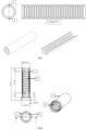
- THE figures 7 and 8 show shapes of ignition charges deposited in the channel of a tube.
- the device according to the invention therefore comprises two assemblies A and B, mounted on the same chassis C, which cooperate, the assembly A which is suitable for maintaining and setting the tube in controlled movements, and the assembly B which is fixed and supports a cylindrical cartridge containing the paste to be deposited.
- the motors (see below) of sets A and B are controlled by a control module D.
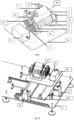
- Set A includes the elements described below, shown on the Figure 9 .
- a system 28 allows the positioning and rotation of the tube 1.
- This system 28 comprises rollers 2a, 2b and 3 arranged in a triangle between which the tube 1 is positioned. Rubber rings 4 are arranged on the rollers 2a and 2b in order to ensure rotational drive contact with the tube 1.
- the rollers 2a and 2b have at their ends a circular shoulder 5 making it possible to hold the tube 1 in position along the axis Y. They also each have, at their own end opposite to assembly B, a toothed wheel 6a, 6b.
- the system 28 comprises a toothed wheel 7 coupled with an axis rotated via a stepper motor 8 controlled by software of the type fitted to 3D printers. The toothed wheel 7 cooperates with the toothed wheels 6a, 6b to rotate the tube 1.
- the three rollers 2a, 2b and 3 are assembled and thus fixed using brackets on the table 9a.
- the roller 3 in the upper position is provided with means allowing it to be released in order to position the tube 1 on the rollers 2a and 2b, then to fold it into contact above the tube 1.
- the roller 3 is held with an articulated arm 10 connected to the table 9a.
- the table 9a is mounted on a second table 9b, the connections between these two tables and the chassis C are made via rings, for example ball bushes (sliding on rails), for guidance, and toothed pulleys and belts for movement, this allowing movement of the table 9a along the axis _ _ _
- the whole thing is controlled by software of the type that equips 3D printers. This degree of freedom allows the table 9a to be released laterally along the axis coincide the axis Yt of tube 1 with the axis Yc of cartridge 19 (see below).
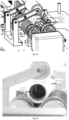
- Set B arranged opposite set A, comprises the elements described below, represented on the Figure 11 .
- a fixed table 13 supports two rings 14a and 14b, such as ball bushings, sliding on guide rails, collinear with the axis Y, allowing the sliding of a carriage 15.
- This carriage 15 is set in motion by a endless screw 16 actuated by a stepper motor 17.
- the carriage 15 makes it possible to set in motion the piston 18 of the cartridge 19 containing the dough via a connecting rod 20.
- the table 13 is arranged on the chassis C.
- the rod 20 and the piston 18 (also called stopper in the terminology specific to syringes) form a single piece.
- the pusher of the piston 18 of the syringe is housed in a central chamber 21, provided with a clasp, of the carriage 15.
- the clasp ensures the connection in the central chamber 21 between the pusher of the piston 18 and the carriage 15.
- a cradle 22 fixed on the table 13 holds the body of the syringe.
- the central chamber 21 of the carriage 15 and the cradle 22 are aligned and arranged so that the axis of the syringe Yc is collinear with the axis Y.
- a tubular extension 23 terminating in a nozzle 24 is arranged at the end of the syringe in place of the original tip of the syringe.
- the cartridge 19 when the cartridge 19 is a cylindrical body provided with a piston, the rod 20 is fixed in the center to the piston 18. At its other end, the rod 20 is held by a clasp in a central chamber 21 of the carriage 15.
- the cartridge 19 is provided at one of its ends with an elbow tubular extension 23 ending in a nozzle 24.
- Two legs 25a and 25b are fixed opposite each other on the table 13.
- the leg 25a has a bore with a countersink and the other 25b a half-bore with a shoulder so as to accommodate the two ends of the cartridge (like a gun for a masonry cartridge).
- the legs 25a and 25b fixed on the table 13 and the central chamber 21 of the carriage 15 are aligned and arranged so that the axis of the cartridge Yc is collinear with the axis Y.
- the invention relates to a method for depositing pasty patterns on the surface (internal or external, preferably internal) of the channel of a tube.
- a mode of implementation of the device of the invention for the deposition of a helical ignition charging pattern on the internal surface of a fuel tube using as a cartridge containing the loading paste. ignition, a cartridge with a cylindrical body fitted with a piston.
- the articulated arm 10 supporting the roller 3 is unfolded and the position of the table 9a is offset relative to the axis Yc of the cartridge so as to facilitate the installation of the tube 1.
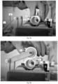
- the tube 1 is placed on reels 2a and 2b as shown on the figure 13a .
- the roller 3 is brought back into contact with the upper part of the tube 1 as shown on the figure 13b .
- the carriage 15 is then moved back towards the motor 17 so as to leave the space for positioning the cartridge 19 free.
- the cartridge 19 containing the paste and provided with its piston 18 connected to the rod 20 is positioned on the legs 25a and 25b .
- the carriage 15 is advanced to secure the end of the rod 20 in the chamber 21 equipped with a clasp.
- the state of the device at this stage of implementation is shown on the Figure 14 .
- the priming of the cartridge 19 allows the filling of the tubular extension 23 and the nozzle 24 with paste by moving the piston 18 until the paste 26 begins to be extruded through the nozzle 24, as shown in there Figure 15 .
- the table 9a is then moved along the axis Figure 16 .
- the table 9b is then moved along the Y axis by means of the motor 12 so as to cause the nozzle 24 for extruding the dough to penetrate the initial point of deposition in the channel of the tube 1, as shown in the figure. Figure 17 .
- the tube 1 is then rotated by means of the motor 8, and the deposition phase is then initiated by simultaneously actuating the motor 12 causing the movement of the tube 1 along the Y axis and of the motor 17 causing the advancement of the piston 18 of the cartridge 19.
- the conjunction of the actions generated by each of the three motors 8, 12 and 17 leads to a helical deposition of paste 27 on the internal surface of the tube as shown on the figures 8 , 18 and 19 .
- the tables 9a and 9b are returned to their initial position and the tube is removed from the device.
- Table 5 can be used for implementing the device as described above.
- Table 5 Tube Dimensions ⁇ int 28.5 mm / Lg Ht: 126 mm Dough density 1.2 g/cm 3 Cartridge size Internal ⁇ : 20.2 mm / Useful length: 78 mm Nozzle diameter ⁇ 6mm Nozzle tilt 235° (or 8h) Speed [Mrot_tube] 2 rpm Speed [My_tube] 14mm/min Speed [My_piston] 7mm/min Linear mass of paste deposited 16.5 g/mL Pattern length 1000mm
- the device of the invention is useful for depositing patterns of pastes inside a tube, and more particularly for obtaining ignition tubes for propellant charges. It can also be used for any application requiring the deposition of patterns in a tube, for example, in the industrial, pharmaceutical or food sector.
Landscapes
- Engineering & Computer Science (AREA)
- General Engineering & Computer Science (AREA)
- Manufacturing & Machinery (AREA)
- Chemical & Material Sciences (AREA)
- Combustion & Propulsion (AREA)
- Organic Chemistry (AREA)
- Life Sciences & Earth Sciences (AREA)
- Wood Science & Technology (AREA)
- Coating Apparatus (AREA)
- Tubes (AREA)
- Basic Packing Technique (AREA)
Description
- Le domaine technique de l'invention est principalement celui des tubes pour chargements propulsifs cylindriques possédant un canal central équipant les munitions.
- Les chargements propulsifs équipant les obus et missiles sont mis en combustion au moyen d'un inflammateur associé à un tube allumeur. Le tube allumeur est formé d'un tube combustible refermant un chargement d'allumage à base de poudre d'allumage à combustion vive. Ce tube allumeur est disposé dans le canal du chargement propulsif.
- La demande de brevet
FR-A-2 593 905 - Toutefois, l'opération de remplissage du tube combustible avec le chargement d'allumage est une opération délicate, en référence tant à la technique de manipulation qu'au risque pyrotechnique (la poudre d'allumage est classée en division de risque 1.1 au sens de au sens de la classification SGH ONU (Système Général Harmonisé de classification et d'étiquetage des produits chimiques (ONU)). Cette opération nécessite des outillages spéciaux pour être automatisée. De plus, lorsque le chargement d'allumage est introduit dans le tube en mélange avec un collodion pour l'obtention (in situ) de comprimés, la durée d'évaporation du solvant du collodion est longue en raison du confinement du collodion chargé dans le tube.
- Par ailleurs, il est parfois nécessaire de démonter le tube allumeur d'un chargement propulsif, par exemple lors d'une mise au rebut d'une munition ou de sa neutralisation. Ce démontage du tube allumeur implique une extraction du chargement d'allumage agencé dans le tube combustible. Cette extraction par contact direct avec la poudre agglomérée génère un danger pyrotechnique.
- La demande de brevet
FR-A-2 725 781 - Il serait donc utile de pouvoir disposer d'un dispositif permettant de déposer dans un tube combustible des motifs pâteux selon des géométries variées, tels qu'ils sont connus par exemple dans
US 3 453 163 A . La présente invention se propose de répondre à cette demande. - La présente invention concerne un dispositif pour le dépôt de motifs pâteux, notamment de chargement d'allumage, sur la surface du canal d'un tube, notamment d'un tube combustible, selon la revendication 1.
- L'invention concerne également un procédé selon la revendication 8 mettant en oeuvre le dispositif susmentionné.
-
- La
figure 1 représente schématiquement les repères de déplacement du dispositif de l'invention dans un tube combustible. - La
figure 2 représente schématiquement les ensembles A et B, le châssis C, et un module de commande D. - La
figure 3 montre l'assemblage des ensembles A et B sur le châssis C. - La
figure 4 montre le déplacement du tube combustible selon l'axe X. - La
figure 5 montre une cartouche mise en oeuvre dans le dispositif de l'invention. - La
figure 6 montre le sens de rotation du tube combustible et l'orientation de la buse pour l'obtention d'un dépôt circulaire ou hélicoïdal. - La
figure 7 illustre un dépôt circulaire de pâte dans un tube combustible. - La
figure 8 illustre un dépôt hélicoïdal de pâte dans un tube combustible. - La
figure 9 représente l'ensemble A du dispositif de l'invention. - La
figure 10 montre les éléments de l'ensemble A assurant les mouvements en X et Y. - La
figure 11 représente une variante de l'ensemble B du dispositif de l'invention. - La
figure 12 représente une variante de l'ensemble B du dispositif de l'invention. - La
figure 13a représente un état du dispositif de l'invention lors de sa mise en oeuvre. - La
figure 13b représente un état du dispositif de l'invention lors de sa mise en oeuvre. - La
figure 14 représente un état du dispositif de l'invention lors de sa mise en oeuvre. - La
figure 15 représente un état du dispositif de l'invention lors de sa mise en oeuvre. - La
figure 16 représente un état du dispositif de l'invention lors de sa mise en oeuvre. - La
figure 17 représente un état du dispositif de l'invention lors de sa mise en oeuvre. - La
figure 18 illustre un dépôt hélicoïdal de pâte dans un tube combustible. - La
figure 19 illustre un dépôt hélicoïdal de pâte dans un tube combustible. - La présente invention concerne, selon un premier aspect, un dispositif pour le dépôt de motifs pâteux, notamment de chargement d'allumage, sur la surface, interne ou externe, de préférence interne, d'un canal d'un tube, notamment un tube combustible. La description qui suit prend pour repère l'axe Y horizontal positionné selon l'axe central du tube, l'axe X selon une direction horizontale orthogonale à l'axe Y, la rotation Z suivant l'axe Y (rotation tube), et la rotation E suivant l'axe Y (rotation vis de poussée seringue), comme montré sur la
figure 1 . - Le dispositif comprend un châssis C supportant deux ensembles mécaniques A et B qui coopèrent:
- un premier ensemble A de maintien, de positionnement et de mise en mouvements du tube ;
- un second ensemble B d'extrusion.
- Comme illustré sur la
figure 2 , le premier ensemble A comprend deux tables superposées permettant le déplacement selon les axes X et Y, et intègre sur la table supérieure un système pour le maintien et la mise en rotation du tube selon un axe de rotation Z. Le deuxième ensemble B comprend une plaque supportant un système de poussée linéaire et une cartouche cylindrique. La cartouche contient la pâte de chargement d'allumage à déposer. La cartouche est prolongée à l'une de ses extrémités par une rallonge tubulaire coudée munie d'une buse d'extrusion, et renferme à son autre extrémité un piston coulissant à mouvement piloté. - Ces deux ensembles A et B sont montés sur un même châssis C de sorte que l'axe longitudinal Yc de la cartouche et l'axe de révolution Yt du tube soient coplanaires dans le plan (X, Y), comme montré sur la
figure 3 . - L'ensemble A dispose d'un axe mobile actionné par un moteur pas à pas permettant de déplacer le tube selon l'axe X et d'aligner l'axe Yt du tube avec l'axe Yc longitudinal de la cartouche, comme montré sur la
figure 4 . - Pour la phase de dépôt, l'ensemble A assure la mise en mouvements du tube, d'une part, de rotation Z autour de son axe central Y et, d'autre part, de translation selon l'axe Y. Les deux mouvements de rotation et de translation sont entraînés séparément par des actionneurs pilotés. Ces actionneurs sont par exemple des moteurs pas à pas pilotés par des interfaces logicielles du type de celles connues pour les imprimantes 3D. Les mouvements de rotation et de translation du tube peuvent être continus ou discontinus par palier à vitesse constante ou variable.
- L'ensemble B supporte une cartouche cylindrique renfermant la pâte de chargement d'allumage montée sur une table fixe, comme montré sur la
figure 5 . La cartouche est orientée selon l'axe Y et est munie à une extrémité, vers le tube, d'une rallonge tubulaire coudée se terminant par une buse d'extrusion. La cartouche, et la buse, ne sont donc pas mobiles selon l'axe Y mais la course de déplacement horizontal du tube selon l'axe Y assurée par l'ensemble A est suffisante pour que la buse pénètre dans le canal du tube sur toute sa longueur. Un piston, actionné dans le corps de la cartouche par un vérin ou une vis sans fin, est apte à se déplacer en translation dans le corps de la cartouche et selon l'axe Yc longitudinal. Le déplacement en translation du vérin ou de la vis est généré par un moteur pas à pas piloté par une interface logicielle, par exemple du type de celle des imprimantes 3D. Pour la phase de dépôt, le débit de pâte par la buse est régulé par le mouvement du piston. La pâte extrudée par la buse se dépose sur la surface du canal du tube pour former le(s) motif(s) souhaité(s). - L'orientation angulaire de la buse dans le plan (Y, Z) est déterminante pour la qualité du dépôt dans le tube. Cette orientation angulaire est fonction notamment de la viscosité de la pâte, de la vitesse de rotation du tube, de l'adhésion de la pâte sur le tube. De façon avantageuse la buse est orientée à environ 225° pour une rotation du tube dans le sens antihoraire pour l'obtention d'un dépôt circulaire ou hélicoïdal (le tube étant alors aussi en mouvement de translation), comme montré sur la
figure 6 . - La coordination des mouvements du tube (en rotation autour de l'axe Y et en translation suivant l'axe Y) et du piston de la cartouche selon l'axe Y, permet de contrôler à chaque instant la position du dépôt dans le canal du tube et la quantité de pâte déposée. Cette coordination est par exemple assurée par un programme informatique de pilotage des moteurs prenant notamment en compte comme données d'entrée les grandeurs caractéristiques du dépôt (masse déposée, motifs...) du chargement d'allumage et celles du tube (diamètre, longueur...).
- Dans un mode de réalisation, la cartouche est conditionnée en température de façon à maintenir la viscosité de la pâte à une valeur permettant son extrusion et sa coulabilité.
- Ce dispositif permet de déposer dans le tube des motifs pâteux selon des géométries variées, par exemple des motifs linéaires dans l'axe du tube, circulaires, hélicoïdaux, triangulaires (chevrons). Plusieurs motifs peuvent être déposés successivement dans le canal du tube, par exemple plusieurs motifs hélicoïdaux décalés angulairement ou des entrelacements de motifs. La quantité de pâte déposée au sein d'un même motif peut aussi varier selon la position dans le canal en faisant varier la vitesse d'avancement du piston de la seringue et/ou les vitesses de rotation/translation du tube. Il est aussi envisageable d'obtenir des motifs de pâtes en compositions différentes, soit en introduisant dans la cartouche au moins deux étages en compositions différentes, soit en répétant l'opération de dépôt avec des cartouches contenant des compositions différentes.
- Le tube est, par exemple, en matière plastique, métallique ou fibreuse. De manière avantageuse, le tube est en matière fibreuse combustible du type des tubes pour chargement propulsif. A titre indicatif, le tube combustible, tel que ceux commercialisés par la société Eurenco, est constitué pour 60% à 80% en masse d'ester cellulosique, 17% à 37% en masse de cellulose, 3% à 7% en masse de résine et 0% à 2% en masse d'additif stabilisant (la somme de ces différents constituants étant égale à 100%). Sa masse est d'environ 15 g à 25 g. Le tube combustible a une hauteur d'environ 120 mm à 140 mm, pour un diamètre intérieur de 25 mm à 30 mm et une épaisseur de 1,5 à 2,5 mm.
- De manière avantageuse, le tube combustible a la composition donnée dans le tableau 1 et les dimensions données ci-après.
Tableau 1 Composition % massique Coton poudre nitrocellulosique 69 Cellulose 25 Résine 5 Additif stabilisant 1 - La masse d'un tel tube combustible est de 18 g +/- 3g, sa hauteur est de 126 mm, pour un diamètre intérieur de 28 mm et une épaisseur de 1,8 mm.
- Dans un mode de réalisation, la surface du tube pourra être préparée, préalablement au dépôt de la pâte, par ponçage ou par dépôt d'un apprêt pour favoriser l'adhésion de la pâte lors du dépôt.
- Dans un mode de réalisation, le tube installé sur le dispositif de l'invention peut être d'une longueur multiple de celle du tube unitaire formant le canal de la munition, il est alors, après dépôt, coupé en tronçons de longueur égale à celle du tube unitaire.
- La cartouche contenant la pâte est par exemple:
- une simple seringue munie de son piston dont l'embout a été découpé pour recevoir la rallonge tubulaire, ou
- une cartouche en plastique munie d'un piston du type de celle utilisée pour l'extrusion de pâtes de maçonnerie ou de joints en silicone, ou
- un corps cylindrique muni d'un piston recevant une poche souple cylindrique du type de celles commercialisées par la société Titanobel ou par la société Würth France.
- Dans un mode de réalisation, la cartouche est automatiquement remplie de pâte par un réservoir de pâte. Un raccord tubulaire entre le réservoir et la cartouche permet alors le remplissage de la cartouche lorsque le piston est reculé, laissant libre le volume de la cartouche. On évite ainsi un remplacement de la cartouche après utilisation de son contenu de pâte pour effectuer un nouveau dépôt.
- La pâte déposée peut conserver son aspect pâteux ou se solidifier (par exemple par évaporation d'un (de) solvant(s) ou réticulation d'un polymère). Les motifs obtenus après dépôt sont donc soit pâteux soit solides selon le produit fini souhaité. Il n'est pas exclu qu'une partie des motifs conserve leur aspect pâteux alors qu'une autre partie soit solidifiée en fonction des compositions de pâtes déposées (par incorporation d'au moins deux compositions différentes dans la cartouche, ou en réalisant successivement au moins deux dépôts avec des compositions différentes).
- Dans un mode de réalisation adapté au dépôt d'un chargement d'allumage dans le tube combustible, la pâte est constituée d'un collodion chargé avec une poudre d'allumage, qui se solidifie par évaporation du ou des solvants après dépôt pour conduire à des motifs solides.
- Le collodion est du type base nitrocellulosique + solvant(s). Dans un mode de réalisation, la base nitrocellulosique du collodion est constituée d'un ester cellulosique (pour environ 70% à environ 90% en masse) et contient généralement en sus, conventionnellement, au moins un plastifiant (environ 1% à environ 20% en masse, préférentiellement environ 10% en masse) et au moins un stabilisant de l'ester cellulosique (environ 0,5% à environ 5% en masse). Il contient aussi généralement au moins un additif (>0% à environ 1% en masse), par exemple choisi parmi les agents anti-adhésion, les agents anti-lueurs, les antioxydants. Il est susceptible de renfermer une quantité résiduelle de solvant(s), notamment de solvant(s) de flegmatisation ou (et) de solvant(s) de dissolution de l'ester cellulosique utilisé(s) lors de sa fabrication.
- De façon avantageuse, l'ester cellulosique utilisé comme composant majoritaire est choisi parmi le nitrate de cellulose, l'acétate de cellulose ou la nitrocellulose, cette dernière étant préférée. La teneur massique en azote de la nitrocellulose est opportunément de 10,5% à 13,5%, un exemple étant la nitrocellulose de grade E avec une teneur massique en azote de 11,8 % à 12,3 %, avantageusement égale à 12%.
- Le plastifiant utilisé pour préparer le collodion peut être notamment une cétone (comme le camphre), un éther vinylique (comme le LUTONAL® A50 commercialisé par la société BASF), un polyuréthane (comme le NEP-PLAST 2001 commercialisé par la société Hagedorn-NC), un adipate (comme l'adipate de dioctyle) ou un citrate (comme le 2-acétyl citrate de triéthyle).
- Le stabilisant utilisé pour préparer le collodion peut être notamment un composé dont la formule chimique comporte des noyaux aromatiques (opportunément deux noyaux aromatiques), apte à fixer les oxydes d'azote de décomposition des esters nitriques (présentement la nitrocellulose). A titre d'exemple de stabilisant on peut citer la 2-nitrodiphénylamine (2NDPA), la 1,3-diéthyl-1,3-diphényl urée (centralite I), la 1,3-diméthyl-1,3-diphényl urée (centralite II), et la 1-méthyl-3-éthyl-1,3-diphényl urée (centralite III).
- L'additif optionnel utilisé pour préparer le collodion peut être notamment choisi parmi les agents antiadhésifs, tels que les agents antiadhésifs de type silicone, les agents anti-lueurs, les antioxydants, les colorants, les tensioactifs, les agents anti-agglomération et les agents hydrophobes.
- Le solvant peut être un double solvant du type acétone/acétate de butyle (AB) à 50% / 50% en masse.
- Le collodion est avantageusement formulé pour conduire à un extrait sec (après évaporation du solvant) de 10% à 40%, en masse.
- A titre indicatif, le tableau 2 ci-dessous présente une formulation du collodion à 14% d'extrait sec en masse.
Tableau 2 Collodion Composition (% en masse) Base nitrocellulosique Nitrocellulose 84 14 Plastifiant 10 Stabilisant 3,5 Autres (additif(s), eau, solvant...) 2,5 Total 100 AB 43 Acétone 43 Total 100 - Dans un mode de réalisation, le collodion chargé en poudre(s) d'allumage comprend environ 50% à environ 70% en masse de poudre(s), et le complément à 100% (c'est-à-dire environ 30% à environ 50% en masse) de collodion. De manière conventionnelle, la ou les poudre(s) d'allumage, préalablement constituée(s), est (sont) ajoutée(s) au collodion.
- De manière conventionnelle, la ou les poudre(s) d'allumage, préalablement constituée(s), est (sont) ajoutée(s) au collodion. La poudre utilisée est préférentiellement de la poudre noire (PN) de composition massique:
- nitrate de potassium (salpêtre) : ~ 75%
- charbon de bois : ~ 15%
- soufre : ~ 10%.
- Le collodion chargé en poudre d'allumage est avantageusement obtenu par ajout de la poudre d'allumage, préalablement constituée, dans le solvant. Il est alors baptisé « Bénite B ». Il se distingue de ceux de l'art antérieur, désignés « Bénite », obtenus par ajouts séparés dans le collodion des constituants de la poudre d'allumage et sans plastifiant. A titre indicatif, le tableau 3 ci-après donne un exemple de composition de collodion du tableau 2, chargé en poudre d'allumage PN7 (qui est une poudre de fine granulométrie).
Tableau 3 Matières premières Masse (g) Composition (% en masse) PN 7 10,36 56 Collodion 8,14 44 Total 18,5 100 - Le collodion chargé en poudre d'allumage est classé en division de risque 1.4 au sens de la classification SGH ONU. Les zones de danger à prendre en compte pour la manipulation du collodion chargé sont donc réduites, ce qui facilite les opérations de dépôt du collodion sur le tube.
- Après séchage (évaporation du solvant) du collodion chargé, le produit sec (i.e., le chargement d'allumage) comprend environ 88% à environ 92% en masse de poudre(s) d'allumage, environ 7% à environ 10% en masse d'ester cellulosique, le complément à 100% étant apporté par au moins un composé choisi parmi un plastifiant, un additif et un solvant résiduel. A titre indicatif, le produit sec obtenu après séchage (évaporation du solvant) du collodion du tableau 3 contient les ratios massiques indiqués dans le tableau 4 ci-après.
Tableau 4 Composition Bénite B sèche Masse (g) % massique PN7 10,36 90,08 Nitrocellulose 0,96 8,35 Plastifiant 0,11 0,96 Stabilisant 0,04 0,35 Résidus (eau, solvant...) 0,03 0,26 Total 11,50 100,00 - La viscosité de la pâte est adaptée de façon à permettre son chargement par coulée dans la cartouche, son extrusion par la buse, et son dépôt non coulant sur le tube.
- Toute géométrie et disposition de motifs sur la surface intérieure (canal) du tube via la mise en oeuvre du dispositif de l'invention peut être envisagée.
- Dans le cas de chargement d'allumage, on retient plus particulièrement des formes de motifs ponctuels espacés, ou de motifs circulaires espacés dans la longueur du canal, ou de motifs linéaires dans la longueur du canal, ou d'un ou plusieurs motifs hélicoïdaux dans la longueur du canal. Les dépôts ne sont pas tous forcément identiques en dimensions et/ou en composition et ne sont pas tous forcément agencés de façon régulière.
- Le nombre de dépôts, leur géométrie, leurs dispositions constituant le chargement d'allumage dans le canal du tube sont des paramètres de réglage du chargement d'allumage. Les
figures 7 et 8 montrent des formes de chargements d'allumage déposés dans le canal d'un tube. - Comme indiqué précédemment, le dispositif conforme à l'invention comprend donc deux ensembles A et B, montés sur un même châssis C, qui coopèrent, l'ensemble A qui convient pour le maintien et la mise en mouvements pilotés du tube, et l'ensemble B qui est fixe et supporte une cartouche cylindrique renfermant la pâte à déposer. Les moteurs (voir ci-après) des ensembles A et B sont asservis par un module de commande D.
- L'ensemble A comprend les éléments décrits ci-après, représentés sur la
figure 9 . - Un système 28 permet le positionnement et la mise en rotation du tube 1. Ce système 28 comprend des rouleaux 2a, 2b et 3 disposés en triangle entre lesquels est positionné le tube 1. Des anneaux en caoutchouc 4 sont disposés sur les rouleaux 2a et 2b afin d'assurer un contact d'entraînement en rotation avec le tube 1. Les rouleaux 2a et 2b comportent à leurs extrémités un épaulement circulaire 5 permettant de maintenir en position le tube 1 selon l'axe Y. Ils comportent aussi chacun, à leur extrémité opposée à l'ensemble B, une roue dentée 6a, 6b. Le système 28 comporte une roue dentée 7 couplée avec un axe mis en rotation via un moteur pas à pas 8 piloté par un logiciel du type de ceux équipant les imprimantes 3D. La roue dentée 7 coopère avec les roues dentées 6a, 6b pour la mise en rotation du tube 1.
- Les trois rouleaux 2a, 2b et 3 sont assemblés et ainsi fixé à l'aide d'équerres sur la table 9a. Le rouleau 3 en position supérieure est pourvu de moyens permettant de le dégager afin de positionner le tube 1 sur les rouleaux 2a et 2b, puis de le rabattre en contact au-dessus du tube 1. Dans un mode de réalisation, le rouleau 3 est maintenu avec un bras articulé 10 relié à la table 9a.
- Comme le montre la
figure 10 , la table 9a est montée sur une seconde table 9b, les liaisons entre ces deux tables et le châssis C sont réalisées par l'intermédiaire de bagues, par exemple des douilles à billes (coulissant sur des rails), pour le guidage, et de poulies crantées et de courroies pour le déplacement, ceci permettant un mouvement de la table 9a selon l'axe X par rapport à la table 9b (mouvement généré par le moteur 11) et un mouvement de la table 9b selon l'axe Y par rapport au châssis C (mouvement généré par le moteur 12). L'ensemble est piloté par un logiciel du type de ceux équipant les imprimantes 3D. Ce degré de liberté permet de dégager latéralement selon l'axe X la table 9a pour faciliter le positionnement et l'enlèvement du tube 1 au sein des trois rouleaux 2a, 2b et 3. Il permet aussi un positionnement précis de la table 9a pour faire coïncider l'axe Yt du tube 1 avec l'axe Yc de la cartouche 19 (voir ci-après). - L'ensemble B, disposé en vis-à-vis de l'ensemble A, comprend les éléments décrits ci-après, représentés sur la
figure 11 . - Une table fixe 13 supporte deux bagues 14a et 14b, telles que des douilles à billes, coulissant sur des rails de guidage, colinéaires à l'axe Y, permettant le coulissement d'un chariot 15. Ce chariot 15 est mis en mouvement par une vis sans fin 16 actionnée par un moteur pas à pas 17. Le chariot 15 permet de mettre en mouvement le piston 18 de la cartouche 19 contenant la pâte par l'intermédiaire d'une tige de liaison 20.
- La table 13 est disposée sur le châssis C. Lorsque la cartouche est une seringue, la tige 20 et le piston 18 (aussi nommé butoir dans la terminologie propre aux seringues) forment une seule pièce. Le poussoir du piston 18 de la seringue est logé dans une chambre centrale 21, munie d'un fermoir, du chariot 15. Le fermoir assure la liaison dans la chambre centrale 21 entre le poussoir du piston 18 et le chariot 15. Un berceau 22 fixé sur la table 13 maintient le corps de la seringue. La chambre centrale 21 du chariot 15 et le berceau 22 sont alignés et disposés de façon à ce que l'axe de la seringue Yc soit colinéaire à l'axe Y. Une rallonge tubulaire 23 terminée par une buse 24 est disposée à l'extrémité de la seringue à la place de l'embout d'origine de la seringue.
- Comme le montre la
figure 12 , lorsque la cartouche 19 est un corps cylindrique muni d'un piston, la tige 20 est fixée au centre au piston 18. A son autre extrémité, la tige 20 est maintenue par un fermoir dans une chambre centrale 21 du chariot 15. La cartouche 19 est munie à une de ses extrémités d'une rallonge tubulaire 23 coudée se terminant par une buse 24. Deux pattes 25a et 25b sont fixées en vis-à-vis sur la table 13. La patte 25a comporte un alésage avec un lamage et l'autre 25b un demi-alésage avec un épaulement de façon à loger les deux extrémités de la cartouche (à la façon d'un pistolet pour cartouche de maçonnerie). Les pattes 25a et 25b fixées sur la table 13 et la chambre centrale 21 du chariot 15 sont alignées et disposées de façon à ce que l'axe de la cartouche Yc soit colinéaire à l'axe Y. - Selon un autre aspect, l'invention concerne un procédé pour déposer des motifs pâteux sur la surface (interne ou externe, de préférence interne) du canal d'un tube. Dans ce qui suit on décrit un mode de mise en oeuvre du dispositif de l'invention pour le dépôt d'un motif hélicoïdal de chargement d'allumage sur la surface interne d'un tube combustible, en utilisant comme cartouche contenant la pâte de chargement d'allumage, une cartouche à corps cylindrique munie d'un piston.
- En début de mise en oeuvre, le bras articulé 10 supportant le rouleau 3 est déplié et la position de la table 9a est décalée par rapport à l'axe Yc de la cartouche de façon à faciliter la mise en place du tube 1. Le tube 1 est placé sur les rouleaux 2a et 2b comme montré sur la
figure 13a . Puis le rouleau 3 est ramené en contact sur la partie supérieure du tube 1 comme montré sur lafigure 13b . - Le chariot 15 est ensuite reculé vers le moteur 17 de façon à laisser libre l'espace de positionnement de la cartouche 19. La cartouche 19 contenant la pâte et munie de son piston 18 relié à la tige 20 est positionnée sur les pattes 25a et 25b. Puis le chariot 15 est avancé pour solidariser l'extrémité de la tige 20 dans la chambre 21 équipée d'un fermoir. L'état du dispositif à ce stade de mise en oeuvre est montré sur la
figure 14 . L'amorçage de la cartouche 19 permet le remplissage en pâte de la rallonge tubulaire 23 et de la buse 24 par déplacement du piston 18 jusqu'à ce que de la pâte 26 commence à être extrudée par la buse 24, comme cela est montré sur lafigure 15 . - La table 9a est ensuite déplacée selon l'axe X par actionnement du moteur 11 de façon à aligner les axes Yt du tube 1 et Yc de la cartouche 19. Le dispositif est alors dans l'état montré sur la
figure 16 . - La table 9b est alors déplacée selon l'axe Y au moyen du moteur 12 de façon à faire pénétrer la buse 24 d'extrusion de la pâte au point initial de dépôt dans le canal du tube 1, comme cela est montré sur la
figure 17 . - Le tube 1 est alors mis en rotation au moyen du moteur 8, et la phase de dépôt est alors enclenchée en actionnant simultanément le moteur 12 provoquant le mouvement du tube 1 selon l'axe Y et du moteur 17 provoquant l'avancement du piston 18 de la cartouche 19. La conjonction des actions générées par chacun des trois moteurs 8, 12 et 17 conduit à un dépôt hélicoïdal de pâte 27 sur la surface interne du tube comme montré sur les
figures 8 ,18 et 19 . Après le dépôt du motif, les tables 9a et 9b sont ramenées dans leur position initiale et le tube est retiré du dispositif. - A titre indicatif, le paramétrage repris dans le tableau 5 peut être utilisé pour la mise en oeuvre du dispositif telle que décrite ci-dessus.
Tableau 5 Dimensions du Tube Ø int 28,5 mm / Lg Ht : 126 mm Densité de la pâte 1,2 g/cm3 Dimension de la cartouche Ø int : 20,2 mm / Lg utile : 78 mm Diamètre de la buse Ø 6mm Inclinaison de la buse 235° (ou 8h) Vitesse [Mrot_tube] 2 tr/min Vitesse [My_tube] 14 mm/min Vitesse [My_piston] 7 mm/ min Masse linéique de pâte déposée 16,5 g/mL Longueur du motif 1000 mm - Le dispositif de l'invention est utile pour le dépôt de motifs de pâtes à l'intérieur d'un tube, et plus particulièrement pour l'obtention de tubes d'allumage pour des charges propulsives. Il peut aussi être utilisé pour toute application nécessitant le dépôt de motifs dans un tube, par exemple, dans le domaine industriel, pharmaceutique ou alimentaire.
Claims (8)
- Dispositif pour le dépôt de motifs pâteux, notamment de chargement d'allumage, sur la surface du canal d'un tube (1), notamment d'un tube combustible, le dispositif comprenant un châssis supportant un premier ensemble mécanique A de maintien, de positionnement et de mise en mouvements du tube, et un second ensemble mécanique B d'extrusion de pâte pour le dépôt desdits motifs pâteux, les ensembles A et B coopérant entre eux ;
caractérisé en ce que l'ensemble A :- comprend une première table (9a) montée sur une deuxième table (9b), ces deux tables permettant le déplacement selon un axe Y horizontal positionné selon l'axe central du tube et selon un axe X positionné selon une direction horizontale orthogonale à l'axe Y, et- intègre sur la première table (9a) un système (28) pour le maintien et la mise en rotation du tube selon un axe de rotation Z. - Dispositif selon la revendication 1, dans lequel la première table (9a) comprend :- un tube (1) positionné entre trois rouleaux (2a, 2b, 3) fixés sur ladite première table (9a), un premier et un deuxième rouleau (2a, 2b) comprenant chacun à une extrémité un épaulement circulaire (5) permettant de maintenir en position le tube (1) selon l'axe Y, et à l'autre extrémité une roue dentée (6a, 6b) ;- un moteur (8) permettant d'entraîner la rotation du premier et du deuxième rouleau (2a, 2b) via un axe couplé à une roue dentée (7) coopérant avec les roues dentées (6a, 6b).
- Dispositif selon la revendication 2, dans lequel un troisième rouleau (3) est pourvu de moyens permettant de le dégager afin de positionner le tube (1) sur le premier et le deuxième rouleau (2a, 2b), puis de le rabattre en contact au-dessus du tube (1),
- Dispositif selon l'une des revendications 1 à 3, dans lequel la deuxième table (9b) est fixée sur le châssis (C), la première table (9a) étant montée sur la deuxième table (9b) de façon à permettre un mouvement de la première table (9a) selon l'axe X par rapport à la deuxième table (9b), et un mouvement de la deuxième table (9b) selon l'axe Y par rapport au châssis (C),
- Dispositif selon l'une des revendications 1 à 4, dans lequel l'ensemble B comprend :- une table fixe (13) supportant deux bagues (14a) et (14b) coulissant sur des rails de guidage, colinéaires à l'axe Y ;- un chariot (15) mis en mouvement par une vis sans fin (16) actionnée par un moteur (17) ;- une cartouche (19) comprenant un piston (18) muni d'une tige de liaison (20), une rallonge tubulaire (23) et une buse (24).
- Dispositif selon la revendication 5, dans lequel la cartouche est une seringue, et dans lequel :- la tige (20) et le piston (18) forment une seule pièce ;- le poussoir du piston (18) de la seringue est logé dans une chambre centrale (21), munie d'un fermoir, du chariot (15) ;- le corps de la seringue est maintenu par un berceau (22) ;- la chambre centrale (21) et le berceau (22) sont alignés et disposés de façon à ce que l'axe de la seringue Yc soit colinéaire à l'axe Y.
- Dispositif selon la revendication 5, dans lequel la cartouche est un corps cylindrique muni d'un piston, et dans lequel :- la tige (20) est fixée au centre au piston (18) ;- à son autre extrémité, la tige (20) est maintenue par un fermoir dans une chambre centrale (21) du chariot (15) ;- une première et une deuxième patte (25a, 25b) sont fixées en vis-à-vis sur la table fixe (13), la première patte (25a) comporte un alésage avec un lamage et la deuxième patte (25b) un demi-alésage avec un épaulement de façon à loger les deux extrémités de la cartouche ;- les pattes (25a) et (25b) et la chambre centrale (21) sont alignées et disposées de façon à ce que l'axe de la cartouche Yc soit colinéaire à l'axe Y.
- Procédé pour déposer des motifs pâteux, notamment de chargement d'allumage, sur la surface du canal d'un tube (1), notamment d'un tube combustible, par mise en oeuvre du dispositif selon l'une quelconque des revendications 1 à 7.
Applications Claiming Priority (2)
| Application Number | Priority Date | Filing Date | Title |
|---|---|---|---|
| FR2000429A FR3106400B1 (fr) | 2020-01-17 | 2020-01-17 | Dispositif pour deposer des motifs pateux dans un tube |
| PCT/FR2021/050067 WO2021144539A1 (fr) | 2020-01-17 | 2021-01-14 | Dispositif pour deposer des motifs pateux dans un tube |
Publications (3)
| Publication Number | Publication Date |
|---|---|
| EP4090909A1 EP4090909A1 (fr) | 2022-11-23 |
| EP4090909C0 EP4090909C0 (fr) | 2024-02-21 |
| EP4090909B1 true EP4090909B1 (fr) | 2024-02-21 |
Family
ID=72088182
Family Applications (1)
| Application Number | Title | Priority Date | Filing Date |
|---|---|---|---|
| EP21719696.3A Active EP4090909B1 (fr) | 2020-01-17 | 2021-01-14 | Dispositif pour deposer des motifs pateux dans un tube |
Country Status (8)
| Country | Link |
|---|---|
| US (1) | US12038263B2 (fr) |
| EP (1) | EP4090909B1 (fr) |
| ES (1) | ES2987580T3 (fr) |
| FR (1) | FR3106400B1 (fr) |
| IL (1) | IL294748B2 (fr) |
| PL (1) | PL4090909T3 (fr) |
| WO (1) | WO2021144539A1 (fr) |
| ZA (1) | ZA202208594B (fr) |
Families Citing this family (2)
| Publication number | Priority date | Publication date | Assignee | Title |
|---|---|---|---|---|
| FR3132712A1 (fr) | 2022-02-15 | 2023-08-18 | Eurenco | Procédé d'obtention de pâtes d'allumage en mélangeur à résonance acoustique |
| FR3139818B1 (fr) * | 2022-09-21 | 2025-06-20 | Eurenco France | Chargements combustibles adhérant à la paroi interne d'une structure combustible contenant un chargement propulsif |
Family Cites Families (8)
| Publication number | Priority date | Publication date | Assignee | Title |
|---|---|---|---|---|
| US3182595A (en) * | 1962-07-20 | 1965-05-11 | Harry F Hassmann | Igniter assembly containing strands of benite |
| US3453163A (en) * | 1967-10-10 | 1969-07-01 | Stone Straw Corp | Method of making helically wound bodies having plastic material extruded on their inner walls |
| FR2593905B1 (fr) | 1986-02-03 | 1990-05-25 | France Etat Armement | Allumeur destructible pour charges propulsives |
| DE3740986A1 (de) * | 1987-12-03 | 1988-06-30 | Bongers Hermann | Treibladungsanzuender mit variabler anfeuerungscharakteristik |
| FR2725781B1 (fr) | 1994-10-18 | 1997-01-24 | Giat Ind Sa | Materiau d'allumage pour charge propulsive et systeme d'allumage ou tube allumeur mettant en oeuvre un tel materiau |
| FR2737002B1 (fr) * | 1995-07-20 | 1997-08-29 | Giat Ind Sa | Systeme d'allumage d'une charge propulsive, notamment pour munition d'artillerie de campagne, et son procede de fabrication |
| DE10328450A1 (de) * | 2003-06-25 | 2005-01-20 | Rheinmetall W & M Gmbh | Verfahren zur Beseitigung von Beschichtungs- und/oder Erosionsschäden |
| US20190351484A1 (en) * | 2018-05-20 | 2019-11-21 | 3D Flexible, Inc. | Metal pastes for additive manufacturing |
-
2020
- 2020-01-17 FR FR2000429A patent/FR3106400B1/fr active Active
-
2021
- 2021-01-13 IL IL294748A patent/IL294748B2/en unknown
- 2021-01-14 PL PL21719696.3T patent/PL4090909T3/pl unknown
- 2021-01-14 EP EP21719696.3A patent/EP4090909B1/fr active Active
- 2021-01-14 US US17/793,473 patent/US12038263B2/en active Active
- 2021-01-14 WO PCT/FR2021/050067 patent/WO2021144539A1/fr not_active Ceased
- 2021-01-14 ES ES21719696T patent/ES2987580T3/es active Active
-
2022
- 2022-08-01 ZA ZA2022/08594A patent/ZA202208594B/en unknown
Also Published As
| Publication number | Publication date |
|---|---|
| ES2987580T3 (es) | 2024-11-15 |
| EP4090909C0 (fr) | 2024-02-21 |
| WO2021144539A1 (fr) | 2021-07-22 |
| IL294748B1 (en) | 2025-10-01 |
| IL294748B2 (en) | 2026-02-01 |
| IL294748A (en) | 2022-09-01 |
| PL4090909T3 (pl) | 2024-11-18 |
| EP4090909A1 (fr) | 2022-11-23 |
| FR3106400A1 (fr) | 2021-07-23 |
| KR20230005114A (ko) | 2023-01-09 |
| ZA202208594B (en) | 2024-01-31 |
| FR3106400B1 (fr) | 2026-04-17 |
| US12038263B2 (en) | 2024-07-16 |
| US20230064872A1 (en) | 2023-03-02 |
Similar Documents
| Publication | Publication Date | Title |
|---|---|---|
| EP4090909A1 (fr) | Dispositif pour deposer des motifs pateux dans un tube | |
| EP4090644B1 (fr) | Tube allumeur pour chargement propulsif | |
| FR2629079A1 (fr) | Procede de production d'un propergol en bloc et produit obtenu | |
| FR2776656A1 (fr) | Procede de fabrication d'un objet a partir d'un materiau granulaire, tube allumeur et charge propulsive obtenus avec un tel procede | |
| FR2480933A1 (fr) | Procede pour amorcer une cartouche a amorce peripherique | |
| WO2022129771A1 (fr) | Procede d'obtention de structures a base de nitrocellulose par fabrication additive | |
| CH625196A5 (fr) | ||
| EP3212594B1 (fr) | Produit pyrotechnique composite performant sans plomb dans sa composition et sa preparation | |
| EP1790626B1 (fr) | Procédé bicomposant semi-continu perfectionné d'obtention d'un chargement explosif composite à matrice polyuréthanne | |
| WO2020109732A1 (fr) | Chargement d'allumage pour munition, procede d'obtention, tube allumeur et systeme d'allumage mettant en œuvre un tel chargement | |
| KR102961092B1 (ko) | 튜브에 페이스트 패턴을 배치하는 장치 | |
| EP0808813B1 (fr) | Procédé continu de fabrication sans solvant de produits pyrotechniques composites thermodurcissables | |
| EP3476821B1 (fr) | Procédé de fabrication d'un produit pyrotechnique composite | |
| EP1333016A2 (fr) | Procédé semi-continu de coulée de pâte de propergol solide, ledit procédé mettant en oeuvre deux composants | |
| EP3515881B1 (fr) | Produit pyrotechnique composite renfermant un agent anti-lueur de type sel de potassium. | |
| EP1741690B1 (fr) | Procédé de fabrication en continu d'un objet pyrotechnique | |
| FR3139818A1 (fr) | Chargements combustibles adhérant à la paroi interne d'une structure combustible contenant un chargement propulsif | |
| EP4479364A1 (fr) | Procédé d'obtention de pâtes d'allumage en mélangeur à résonance acoustique | |
| EP1584610A2 (fr) | Composition explosive | |
| EP1767574A1 (fr) | Procédé de fabrication de compositions énergétiques comprenant des nanoparticules d'un élément ou composé chimique dispersées dans une matrice organique | |
| US20070169864A1 (en) | Method for supplying pyrotechnic material slurry | |
| CA2968255A1 (fr) | Produits explosifs composites de faible epaisseur et leur preparation | |
| FR2984885A1 (fr) | Procede de fabrication de granules d'une composition explosive comprimable et materiau esplosif obtenu avec un tel procede |
Legal Events
| Date | Code | Title | Description |
|---|---|---|---|
| STAA | Information on the status of an ep patent application or granted ep patent |
Free format text: STATUS: UNKNOWN |
|
| STAA | Information on the status of an ep patent application or granted ep patent |
Free format text: STATUS: THE INTERNATIONAL PUBLICATION HAS BEEN MADE |
|
| PUAI | Public reference made under article 153(3) epc to a published international application that has entered the european phase |
Free format text: ORIGINAL CODE: 0009012 |
|
| STAA | Information on the status of an ep patent application or granted ep patent |
Free format text: STATUS: REQUEST FOR EXAMINATION WAS MADE |
|
| 17P | Request for examination filed |
Effective date: 20220715 |
|
| AK | Designated contracting states |
Kind code of ref document: A1 Designated state(s): AL AT BE BG CH CY CZ DE DK EE ES FI FR GB GR HR HU IE IS IT LI LT LU LV MC MK MT NL NO PL PT RO RS SE SI SK SM TR |
|
| DAV | Request for validation of the european patent (deleted) | ||
| DAX | Request for extension of the european patent (deleted) | ||
| GRAP | Despatch of communication of intention to grant a patent |
Free format text: ORIGINAL CODE: EPIDOSNIGR1 |
|
| STAA | Information on the status of an ep patent application or granted ep patent |
Free format text: STATUS: GRANT OF PATENT IS INTENDED |
|
| INTG | Intention to grant announced |
Effective date: 20230803 |
|
| GRAS | Grant fee paid |
Free format text: ORIGINAL CODE: EPIDOSNIGR3 |
|
| GRAA | (expected) grant |
Free format text: ORIGINAL CODE: 0009210 |
|
| STAA | Information on the status of an ep patent application or granted ep patent |
Free format text: STATUS: THE PATENT HAS BEEN GRANTED |
|
| AK | Designated contracting states |
Kind code of ref document: B1 Designated state(s): AL AT BE BG CH CY CZ DE DK EE ES FI FR GB GR HR HU IE IS IT LI LT LU LV MC MK MT NL NO PL PT RO RS SE SI SK SM TR |
|
| REG | Reference to a national code |
Ref country code: GB Ref legal event code: FG4D Free format text: NOT ENGLISH |
|
| REG | Reference to a national code |
Ref country code: CH Ref legal event code: EP |
|
| REG | Reference to a national code |
Ref country code: IE Ref legal event code: FG4D Free format text: LANGUAGE OF EP DOCUMENT: FRENCH |
|
| REG | Reference to a national code |
Ref country code: DE Ref legal event code: R096 Ref document number: 602021009636 Country of ref document: DE |
|
| U01 | Request for unitary effect filed |
Effective date: 20240319 |
|
| U07 | Unitary effect registered |
Designated state(s): AT BE BG DE DK EE FI FR IT LT LU LV MT NL PT SE SI Effective date: 20240326 |
|
| REG | Reference to a national code |
Ref country code: CH Ref legal event code: PK Free format text: DIE PUBLIKATION VOM 17.04.2024 WURDE AM 24.04.2024 IRRTUEMLICHERWEISE ERNEUT PUBLIZIERT. LA PUBLICATION DU 17.04.2024 A ETE REPUBLIEE PAR ERREUR LE 24.04.2024. LA PUBBLICAZIONE DEL 17.04.2024 E STATA ERRONEAMENTE RIPUBBLICATA IL 24.04.2024. |
|
| RAP4 | Party data changed (patent owner data changed or rights of a patent transferred) |
Owner name: EURENCO FRANCE SAS |
|
| U1H | Name or address of the proprietor changed after the registration of the unitary effect |
Owner name: EURENCO FRANCE SAS; FR |
|
| PG25 | Lapsed in a contracting state [announced via postgrant information from national office to epo] |
Ref country code: IS Free format text: LAPSE BECAUSE OF FAILURE TO SUBMIT A TRANSLATION OF THE DESCRIPTION OR TO PAY THE FEE WITHIN THE PRESCRIBED TIME-LIMIT Effective date: 20240621 |
|
| PG25 | Lapsed in a contracting state [announced via postgrant information from national office to epo] |
Ref country code: GR Free format text: LAPSE BECAUSE OF FAILURE TO SUBMIT A TRANSLATION OF THE DESCRIPTION OR TO PAY THE FEE WITHIN THE PRESCRIBED TIME-LIMIT Effective date: 20240522 |
|
| PG25 | Lapsed in a contracting state [announced via postgrant information from national office to epo] |
Ref country code: RS Free format text: LAPSE BECAUSE OF FAILURE TO SUBMIT A TRANSLATION OF THE DESCRIPTION OR TO PAY THE FEE WITHIN THE PRESCRIBED TIME-LIMIT Effective date: 20240521 Ref country code: HR Free format text: LAPSE BECAUSE OF FAILURE TO SUBMIT A TRANSLATION OF THE DESCRIPTION OR TO PAY THE FEE WITHIN THE PRESCRIBED TIME-LIMIT Effective date: 20240221 |
|
| REG | Reference to a national code |
Ref country code: SK Ref legal event code: T3 Ref document number: E 44162 Country of ref document: SK |
|
| PG25 | Lapsed in a contracting state [announced via postgrant information from national office to epo] |
Ref country code: RS Free format text: LAPSE BECAUSE OF FAILURE TO SUBMIT A TRANSLATION OF THE DESCRIPTION OR TO PAY THE FEE WITHIN THE PRESCRIBED TIME-LIMIT Effective date: 20240521 Ref country code: IS Free format text: LAPSE BECAUSE OF FAILURE TO SUBMIT A TRANSLATION OF THE DESCRIPTION OR TO PAY THE FEE WITHIN THE PRESCRIBED TIME-LIMIT Effective date: 20240621 Ref country code: HR Free format text: LAPSE BECAUSE OF FAILURE TO SUBMIT A TRANSLATION OF THE DESCRIPTION OR TO PAY THE FEE WITHIN THE PRESCRIBED TIME-LIMIT Effective date: 20240221 Ref country code: GR Free format text: LAPSE BECAUSE OF FAILURE TO SUBMIT A TRANSLATION OF THE DESCRIPTION OR TO PAY THE FEE WITHIN THE PRESCRIBED TIME-LIMIT Effective date: 20240522 |
|
| PG25 | Lapsed in a contracting state [announced via postgrant information from national office to epo] |
Ref country code: SM Free format text: LAPSE BECAUSE OF FAILURE TO SUBMIT A TRANSLATION OF THE DESCRIPTION OR TO PAY THE FEE WITHIN THE PRESCRIBED TIME-LIMIT Effective date: 20240221 |
|
| PG25 | Lapsed in a contracting state [announced via postgrant information from national office to epo] |
Ref country code: SM Free format text: LAPSE BECAUSE OF FAILURE TO SUBMIT A TRANSLATION OF THE DESCRIPTION OR TO PAY THE FEE WITHIN THE PRESCRIBED TIME-LIMIT Effective date: 20240221 Ref country code: RO Free format text: LAPSE BECAUSE OF FAILURE TO SUBMIT A TRANSLATION OF THE DESCRIPTION OR TO PAY THE FEE WITHIN THE PRESCRIBED TIME-LIMIT Effective date: 20240221 |
|
| REG | Reference to a national code |
Ref country code: ES Ref legal event code: FG2A Ref document number: 2987580 Country of ref document: ES Kind code of ref document: T3 Effective date: 20241115 |
|
| REG | Reference to a national code |
Ref country code: DE Ref legal event code: R097 Ref document number: 602021009636 Country of ref document: DE |
|
| PLBE | No opposition filed within time limit |
Free format text: ORIGINAL CODE: 0009261 |
|
| STAA | Information on the status of an ep patent application or granted ep patent |
Free format text: STATUS: NO OPPOSITION FILED WITHIN TIME LIMIT |
|
| 26N | No opposition filed |
Effective date: 20241122 |
|
| U20 | Renewal fee for the european patent with unitary effect paid |
Year of fee payment: 5 Effective date: 20250117 |
|
| REG | Reference to a national code |
Ref country code: CH Ref legal event code: PL |
|
| PG25 | Lapsed in a contracting state [announced via postgrant information from national office to epo] |
Ref country code: MC Free format text: LAPSE BECAUSE OF FAILURE TO SUBMIT A TRANSLATION OF THE DESCRIPTION OR TO PAY THE FEE WITHIN THE PRESCRIBED TIME-LIMIT Effective date: 20240221 |
|
| GBPC | Gb: european patent ceased through non-payment of renewal fee |
Effective date: 20250114 |
|
| PG25 | Lapsed in a contracting state [announced via postgrant information from national office to epo] |
Ref country code: GB Free format text: LAPSE BECAUSE OF NON-PAYMENT OF DUE FEES Effective date: 20250114 |
|
| PG25 | Lapsed in a contracting state [announced via postgrant information from national office to epo] |
Ref country code: CH Free format text: LAPSE BECAUSE OF NON-PAYMENT OF DUE FEES Effective date: 20250131 |
|
| PGFP | Annual fee paid to national office [announced via postgrant information from national office to epo] |
Ref country code: NO Payment date: 20251230 Year of fee payment: 6 |
|
| PG25 | Lapsed in a contracting state [announced via postgrant information from national office to epo] |
Ref country code: IE Free format text: LAPSE BECAUSE OF NON-PAYMENT OF DUE FEES Effective date: 20250114 |
|
| PGFP | Annual fee paid to national office [announced via postgrant information from national office to epo] |
Ref country code: CZ Payment date: 20251216 Year of fee payment: 6 |
|
| PGFP | Annual fee paid to national office [announced via postgrant information from national office to epo] |
Ref country code: PL Payment date: 20251209 Year of fee payment: 6 |
|
| PGFP | Annual fee paid to national office [announced via postgrant information from national office to epo] |
Ref country code: SK Payment date: 20251216 Year of fee payment: 6 |
|
| U20 | Renewal fee for the european patent with unitary effect paid |
Year of fee payment: 6 Effective date: 20260120 |
|
| PGFP | Annual fee paid to national office [announced via postgrant information from national office to epo] |
Ref country code: ES Payment date: 20260209 Year of fee payment: 6 |