EP4090909B1 - Vorrichtung zum verlegen von pastenmustern in einem rohr - Google Patents
Vorrichtung zum verlegen von pastenmustern in einem rohr Download PDFInfo
- Publication number
- EP4090909B1 EP4090909B1 EP21719696.3A EP21719696A EP4090909B1 EP 4090909 B1 EP4090909 B1 EP 4090909B1 EP 21719696 A EP21719696 A EP 21719696A EP 4090909 B1 EP4090909 B1 EP 4090909B1
- Authority
- EP
- European Patent Office
- Prior art keywords
- tube
- axis
- cartridge
- along
- piston
- Prior art date
- Legal status (The legal status is an assumption and is not a legal conclusion. Google has not performed a legal analysis and makes no representation as to the accuracy of the status listed.)
- Active
Links
Images


Classifications
-
- F—MECHANICAL ENGINEERING; LIGHTING; HEATING; WEAPONS; BLASTING
- F42—AMMUNITION; BLASTING
- F42C—AMMUNITION FUZES; ARMING OR SAFETY MEANS THEREFOR
- F42C19/00—Details of fuzes
- F42C19/08—Primers; Detonators
- F42C19/0823—Primers or igniters for the initiation or the propellant charge in a cartridged ammunition
- F42C19/0826—Primers or igniters for the initiation or the propellant charge in a cartridged ammunition comprising an elongated perforated tube, i.e. flame tube, for the transmission of the initial energy to the propellant charge, e.g. used for artillery shells and kinetic energy penetrators
-
- B—PERFORMING OPERATIONS; TRANSPORTING
- B05—SPRAYING OR ATOMISING IN GENERAL; APPLYING FLUENT MATERIALS TO SURFACES, IN GENERAL
- B05D—PROCESSES FOR APPLYING FLUENT MATERIALS TO SURFACES, IN GENERAL
- B05D1/00—Processes for applying liquids or other fluent materials
- B05D1/002—Processes for applying liquids or other fluent materials the substrate being rotated
-
- F—MECHANICAL ENGINEERING; LIGHTING; HEATING; WEAPONS; BLASTING
- F42—AMMUNITION; BLASTING
- F42B—EXPLOSIVE CHARGES, e.g. FOR BLASTING, FIREWORKS, AMMUNITION
- F42B3/00—Blasting cartridges, i.e. case and explosive
- F42B3/10—Initiators therefor
- F42B3/195—Manufacture
-
- C—CHEMISTRY; METALLURGY
- C06—EXPLOSIVES; MATCHES
- C06C—DETONATING OR PRIMING DEVICES; FUSES; CHEMICAL LIGHTERS; PYROPHORIC COMPOSITIONS
- C06C7/00—Non-electric detonators; Blasting caps; Primers
- C06C7/02—Manufacture; Packing
-
- F—MECHANICAL ENGINEERING; LIGHTING; HEATING; WEAPONS; BLASTING
- F42—AMMUNITION; BLASTING
- F42B—EXPLOSIVE CHARGES, e.g. FOR BLASTING, FIREWORKS, AMMUNITION
- F42B3/00—Blasting cartridges, i.e. case and explosive
- F42B3/10—Initiators therefor
-
- F—MECHANICAL ENGINEERING; LIGHTING; HEATING; WEAPONS; BLASTING
- F42—AMMUNITION; BLASTING
- F42B—EXPLOSIVE CHARGES, e.g. FOR BLASTING, FIREWORKS, AMMUNITION
- F42B33/00—Manufacture of ammunition; Dismantling of ammunition; Apparatus therefor
- F42B33/02—Filling cartridges, missiles, or fuzes; Inserting propellant or explosive charges
- F42B33/0207—Processes for loading or filling propulsive or explosive charges in containers
-
- B—PERFORMING OPERATIONS; TRANSPORTING
- B05—SPRAYING OR ATOMISING IN GENERAL; APPLYING FLUENT MATERIALS TO SURFACES, IN GENERAL
- B05D—PROCESSES FOR APPLYING FLUENT MATERIALS TO SURFACES, IN GENERAL
- B05D1/00—Processes for applying liquids or other fluent materials
- B05D1/26—Processes for applying liquids or other fluent materials performed by applying the liquid or other fluent material from an outlet device in contact with, or almost in contact with, the surface
-
- B—PERFORMING OPERATIONS; TRANSPORTING
- B05—SPRAYING OR ATOMISING IN GENERAL; APPLYING FLUENT MATERIALS TO SURFACES, IN GENERAL
- B05D—PROCESSES FOR APPLYING FLUENT MATERIALS TO SURFACES, IN GENERAL
- B05D7/00—Processes, other than flocking, specially adapted for applying liquids or other fluent materials to particular surfaces or for applying particular liquids or other fluent materials
- B05D7/22—Processes, other than flocking, specially adapted for applying liquids or other fluent materials to particular surfaces or for applying particular liquids or other fluent materials to internal surfaces, e.g. of tubes
Definitions
- the technical field of the invention is mainly that of tubes for cylindrical propellant charges having a central channel equipping the munitions.
- the propellant charges fitted to the shells and missiles are ignited by means of an igniter associated with an igniter tube.
- the igniter tube is formed of a fuel tube enclosing an ignition charge based on lively combustion ignition powder. This igniter tube is placed in the propellant loading channel.
- the patent application FR-A-2 593 905 describes an ignition charge placed in a fuel tube consisting of a stack of tablets of agglomerated ignition powder. These igniter tube assemblies require on the one hand the manufacture of agglomerated powder tablets, and on the other hand their placement in the fuel tube.
- the operation of filling the fuel tube with the ignition charge is a delicate operation, with reference to both the handling technique and the pyrotechnic risk (the ignition powder is classified in risk division 1.1 within the meaning of within the meaning of the UN GHS classification (Generally Harmonized System of Classification and Labeling of Chemicals (UN)).
- This operation requires special tools to be automated.
- the ignition charge is introduced into the tube in mixed with a collodion to obtain ( in situ ) tablets, the evaporation time of the collodion solvent is long due to the confinement of the collodion loaded in the tube.
- the patent application FR-A-2 725 781 proposes a method to better distribute the powder charge in the ammunition channel and facilitates the disassembly of the ignition material compared to the agglomerated powder ignition material.
- the agglomerated powder tablets are replaced by an ignition material comprising an ignition composition in powder form (typically the black powder) deposited on a flexible support sheet, which is then advantageously rolled up on itself in order to be inserted into a fuel tube to form an igniter tube. So that the powder (which is just placed on the flexible support) does not fall to the bottom of the igniter tube, it is imperative to coat the powder composition with another flexible sheet (called a screen sheet), at least one of the screen and support sheets. being coated with glue.
- a screen sheet another flexible sheet
- the implementation of this process is complex due to the handling of the explosive ignition powder classified in risk division 1.1, the control of the regularity of the quantities of powders deposited in piles on the flexible sheet and the geometries of the piles, of the step of covering the piles of powders deposited on the flexible sheet by the sticky screen sheet.
- the configuration possibilities of pyrotechnic objects are limited and controlled solely by the mass and spatial distribution of the piles of powdery powder.
- the present invention relates to a device for depositing pasty patterns, in particular ignition charging, on the surface of the channel of a tube, in particular of a fuel tube, according to claim 1.
- the invention also relates to a method according to claim 8 using the aforementioned device.
- the present invention relates, according to a first aspect, to a device for depositing pasty patterns, in particular ignition loading, on the internal or external, preferably internal, surface of a channel of a tube, in particular a tube combustible.
- a device for depositing pasty patterns, in particular ignition loading on the internal or external, preferably internal, surface of a channel of a tube, in particular a tube combustible.
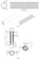
- the following description takes as reference the horizontal Y axis positioned along the central axis of the tube, the X axis in a horizontal direction orthogonal to the Y axis, the Z rotation along the Y axis (tube rotation), and rotation E along the Y axis (syringe push screw rotation), as shown on the figure 1 .
- the first set A comprises two superimposed tables allowing movement along the X and Y axes, and integrates on the upper table a system for maintaining and rotating the tube along an axis of rotation Z.
- the second set B includes plate supporting a linear thrust system and a cylindrical cartridge.
- the cartridge contains the ignition loading paste to be deposited.
- the cartridge is extended at one of its ends by a bent tubular extension fitted with an extrusion nozzle, and at its other end contains a sliding piston with controlled movement.
- Assembly A has a movable axis actuated by a stepper motor allowing the tube to be moved along the X axis and to align the Yt axis of the tube with the longitudinal Yc axis of the cartridge, as shown on there figure 4 .
- assembly A ensures the movement of the tube, on the one hand, of rotation Z around its central axis Y and, on the other hand, of translation along the axis Y.
- the two movements rotation and translation are driven separately by controlled actuators.
- actuators are for example stepper motors controlled by software interfaces of the type known for 3D printers.
- the rotational and translational movements of the tube can be continuous or discontinuous in stages at constant or variable speed.
- Assembly B supports a cylindrical cartridge containing the ignition charging paste mounted on a fixed table, as shown in the Figure 5 .
- the cartridge is oriented along the Y axis and is provided at one end, towards the tube, with an elbowed tubular extension ending in an extrusion nozzle.
- the cartridge, and the nozzle are therefore not movable along the Y axis but the stroke of horizontal movement of the tube along the Y axis provided by assembly A is sufficient for the nozzle to enter the channel of the tube over all its length.
- a piston, actuated in the body of the cartridge by a jack or an endless screw, is capable of moving in translation in the body of the cartridge and along the longitudinal axis Yc.
- the translational movement of the cylinder or the screw is generated by a stepper motor controlled by a software interface, for example of the type used in 3D printers.
- a software interface for example of the type used in 3D printers.
- the flow of paste through the nozzle is regulated by the movement of the piston.
- the paste extruded by the nozzle is deposited on the surface of the tube channel to form the desired pattern(s).
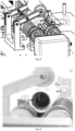
- the angular orientation of the nozzle in the plane (Y, Z) is decisive for the quality of the deposit in the tube. This angular orientation depends in particular on the viscosity of the paste, the speed of rotation of the tube, and the adhesion of the paste to the tube.
- the nozzle is oriented at approximately 225° for rotation of the tube in a counterclockwise direction to obtain a circular or helical deposit (the tube then also being in translation movement), as shown in the Figure 6 .
- the coordination of the movements of the tube (in rotation around the Y axis and in translation along the Y axis) and of the piston of the cartridge along the Y axis, makes it possible to control at each instant the position of the deposit in the tube channel and the quantity of paste deposited.
- This coordination is for example ensured by a computer program for controlling the engines taking into account in particular as input data the characteristic quantities of the deposit (mass deposited, patterns, etc.) of the ignition charge and those of the tube (diameter, length ).
- the cartridge is temperature conditioned so as to maintain the viscosity of the paste at a value allowing its extrusion and flowability.
- This device makes it possible to deposit pasty patterns in the tube according to varied geometries, for example linear patterns in the axis of the tube, circular, helical, triangular (chevrons).
- Several patterns can be deposited successively in the channel of the tube, for example several angularly offset helical patterns or interlacing of patterns.
- the quantity of paste deposited within the same pattern can also vary depending on the position in the channel by varying the speed of advancement of the piston of the syringe and/or the rotation/translation speeds of the tube. It is also possible to obtain paste patterns with different compositions, either by introducing into the cartridge at least two stages with different compositions, or by repeating the deposition operation with cartridges containing different compositions.
- the tube is, for example, made of plastic, metallic or fibrous material.
- the tube is made of combustible fibrous material of the type used for propellant loading tubes.
- the fuel tube such as those marketed by the company Eurenco, is made up of 60% to 80% by mass of cellulose ester, 17% to 37% by mass of cellulose, 3% to 7% by mass of resin and 0% to 2% by weight of stabilizing additive (the sum of these different constituents being equal to 100%). Its mass is approximately 15 g to 25 g.
- the fuel tube has a height of approximately 120 mm to 140 mm, an internal diameter of 25 mm to 30 mm and a thickness of 1.5 to 2.5 mm.
- the fuel tube has the composition given in Table 1 and the dimensions given below.
- Table 1 Composition % by mass Nitrocellulose powder cotton 69 Cellulose 25 Resin 5 Stabilizing additive 1
- the mass of such a fuel tube is 18 g +/- 3g, its height is 126 mm, for an internal diameter of 28 mm and a thickness of 1.8 mm.
- the surface of the tube can be prepared, prior to depositing the paste, by sanding or by depositing a primer to promote adhesion of the paste during deposition.
- the tube installed on the device of the invention can be of a length multiple of that of the unit tube forming the channel of the ammunition, it is then, after deposition, cut into sections of length equal to that of the unit tube.
- the cartridge is automatically filled with paste from a paste reservoir.
- a tubular connection between the reservoir and the cartridge then allows the cartridge to be filled when the piston is moved back, leaving the volume of the cartridge free. This avoids replacing the cartridge after using its paste contents to make a new deposit.
- the deposited paste can retain its pasty appearance or solidify (for example by evaporation of a solvent(s) or crosslinking of a polymer).
- the patterns obtained after deposition are therefore either pasty or solid depending on the desired finished product. It is not excluded that part of the patterns retain their pasty appearance while another part is solidified depending on the paste compositions deposited (by incorporation of at least two different compositions in the cartridge, or by successively producing least two deposits with different compositions).
- the paste consists of a collodion loaded with an ignition powder, which solidifies by evaporation of the solvent(s) after deposition to lead to solid patterns.
- the collodion is of the nitrocellulose base + solvent(s) type.
- the nitrocellulose base of the collodion consists of a cellulose ester (approximately 70% to approximately 90% by weight) and generally additionally contains, conventionally, at least one plasticizer (approximately 1% to approximately 20% by mass, preferably approximately 10% by mass) and at least one cellulose ester stabilizer (approximately 0.5% to approximately 5% by mass). It also generally contains at least one additive (>0% to approximately 1% by weight), for example chosen from anti-adhesion agents, anti-glow agents, antioxidants. It is likely to contain a residual quantity of solvent(s), in particular phlegmatization solvent(s) or (and) solvent(s) for dissolving the cellulose ester used during its manufacture.
- the cellulose ester used as the majority component is chosen from cellulose nitrate, cellulose acetate or nitrocellulose, the latter being preferred.
- the nitrogen mass content of nitrocellulose is conveniently from 10.5% to 13.5%, an example being grade E nitrocellulose with a nitrogen mass content of 11.8% to 12.3%, advantageously equal to 12 %.
- the plasticizer used to prepare the collodion may in particular be a ketone (such as camphor), a vinyl ether (such as LUTONAL ® A50 marketed by the company BASF), a polyurethane (such as NEP-PLAST 2001 marketed by the company Hagedorn-NC ), an adipate (such as dioctyl adipate) or a citrate (such as triethyl 2-acetyl citrate).
- a ketone such as camphor
- a vinyl ether such as LUTONAL ® A50 marketed by the company BASF
- a polyurethane such as NEP-PLAST 2001 marketed by the company Hagedorn-NC
- an adipate such as dioctyl adipate
- a citrate such as triethyl 2-acetyl citrate
- the stabilizer used to prepare the collodion may in particular be a compound whose chemical formula includes aromatic nuclei (opportunity two aromatic nuclei), capable of fixing the nitrogen oxides from the decomposition of nitric esters (currently nitrocellulose).
- aromatic nuclei aromatic nuclei
- a stabilizer mention may be made of 2-nitrodiphenylamine (2NDPA), 1,3-diethyl-1,3-diphenyl urea (centralite I), 1,3-dimethyl-1,3-diphenyl urea ( centralite II), and 1-methyl-3-ethyl-1,3-diphenyl urea (centralite III).
- the optional additive used to prepare the collodion can be chosen in particular from non-stick agents, such as silicone-type non-stick agents, anti-glow agents, antioxidants, dyes, surfactants, anti-caking agents and hydrophobic agents.
- non-stick agents such as silicone-type non-stick agents, anti-glow agents, antioxidants, dyes, surfactants, anti-caking agents and hydrophobic agents.
- the solvent can be a double solvent of the acetone/butyl acetate (AB) type at 50%/50% by weight.
- the collodion is advantageously formulated to produce a dry extract (after evaporation of the solvent) of 10% to 40%, by mass.
- Table 2 presents a formulation of collodion with 14% dry extract by mass.
- Table 2 Collodion Composition (% by mass) Nitrocellulose base Nitrocellulose 84 14 Plasticizer 10 Stabilizing 3.5 Others (additive(s), water, solvent%) 2.5 Total 100 AB 43 Acetone 43 Total 100
- the collodion loaded with ignition powder(s) comprises approximately 50% to approximately 70% by mass of powder(s), and the remainder at 100% (i.e. approximately 30% approximately 50% by mass) of collodion.
- the ignition powder(s), previously constituted, is(are) added to the collodion.
- the collodion loaded with ignition powder is advantageously obtained by adding the ignition powder, previously constituted, to the solvent. It is then baptized “Bénite B”. It differs from those of the prior art, designated “Bénite”, obtained by separate additions to the collodion of the constituents of the ignition powder and without plasticizer.
- Table 3 gives an example of the collodion composition from Table 2, loaded with PN7 ignition powder (which is a powder of fine particle size). Table 3 Raw materials Mass (g) Composition (% by mass) PN 7 10.36 56 Collodion 8.14 44 Total 18.5 100
- Collodion loaded with ignition powder is classified in risk division 1.4 within the meaning of the UN GHS classification.
- the danger zones to be taken into account for handling the loaded collodion are therefore reduced, which facilitates the operations of depositing the collodion on the tube.
- the dry product ie, the ignition charge
- the dry product obtained after drying (evaporation of the solvent) of the collodion in Table 3 contains the mass ratios indicated in Table 4 below.
- Table 4 Composition Bénite B dry Mass (g) % by mass PN7 10.36 90.08 Nitrocellulose 0.96 8.35 Plasticizer 0.11 0.96 Stabilizing 0.04 0.35 Residues (water, solvent, etc.) 0.03 0.26 Total 11.50 100.00
- the viscosity of the paste is adapted to allow its loading by pouring into the cartridge, its extrusion through the nozzle, and its non-flowing deposition on the tube.
- the number of deposits, their geometry, their arrangements constituting the ignition load in the tube channel are parameters for adjusting the ignition load.
- THE figures 7 and 8 show shapes of ignition charges deposited in the channel of a tube.
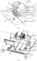
- the device according to the invention therefore comprises two assemblies A and B, mounted on the same chassis C, which cooperate, the assembly A which is suitable for maintaining and setting the tube in controlled movements, and the assembly B which is fixed and supports a cylindrical cartridge containing the paste to be deposited.
- the motors (see below) of sets A and B are controlled by a control module D.
- Set A includes the elements described below, shown on the Figure 9 .
- a system 28 allows the positioning and rotation of the tube 1.
- This system 28 comprises rollers 2a, 2b and 3 arranged in a triangle between which the tube 1 is positioned. Rubber rings 4 are arranged on the rollers 2a and 2b in order to ensure rotational drive contact with the tube 1.
- the rollers 2a and 2b have at their ends a circular shoulder 5 making it possible to hold the tube 1 in position along the axis Y. They also each have, at their own end opposite to assembly B, a toothed wheel 6a, 6b.
- the system 28 comprises a toothed wheel 7 coupled with an axis rotated via a stepper motor 8 controlled by software of the type fitted to 3D printers. The toothed wheel 7 cooperates with the toothed wheels 6a, 6b to rotate the tube 1.
- the three rollers 2a, 2b and 3 are assembled and thus fixed using brackets on the table 9a.
- the roller 3 in the upper position is provided with means allowing it to be released in order to position the tube 1 on the rollers 2a and 2b, then to fold it into contact above the tube 1.
- the roller 3 is held with an articulated arm 10 connected to the table 9a.
- the table 9a is mounted on a second table 9b, the connections between these two tables and the chassis C are made via rings, for example ball bushes (sliding on rails), for guidance, and toothed pulleys and belts for movement, this allowing movement of the table 9a along the axis _ _ _
- the whole thing is controlled by software of the type that equips 3D printers. This degree of freedom allows the table 9a to be released laterally along the axis coincide the axis Yt of tube 1 with the axis Yc of cartridge 19 (see below).
- Set B arranged opposite set A, comprises the elements described below, represented on the Figure 11 .
- a fixed table 13 supports two rings 14a and 14b, such as ball bushings, sliding on guide rails, collinear with the axis Y, allowing the sliding of a carriage 15.
- This carriage 15 is set in motion by a endless screw 16 actuated by a stepper motor 17.
- the carriage 15 makes it possible to set in motion the piston 18 of the cartridge 19 containing the dough via a connecting rod 20.
- the table 13 is arranged on the chassis C.
- the rod 20 and the piston 18 (also called stopper in the terminology specific to syringes) form a single piece.
- the pusher of the piston 18 of the syringe is housed in a central chamber 21, provided with a clasp, of the carriage 15.
- the clasp ensures the connection in the central chamber 21 between the pusher of the piston 18 and the carriage 15.
- a cradle 22 fixed on the table 13 holds the body of the syringe.
- the central chamber 21 of the carriage 15 and the cradle 22 are aligned and arranged so that the axis of the syringe Yc is collinear with the axis Y.
- a tubular extension 23 terminating in a nozzle 24 is arranged at the end of the syringe in place of the original tip of the syringe.
- the cartridge 19 when the cartridge 19 is a cylindrical body provided with a piston, the rod 20 is fixed in the center to the piston 18. At its other end, the rod 20 is held by a clasp in a central chamber 21 of the carriage 15.
- the cartridge 19 is provided at one of its ends with an elbow tubular extension 23 ending in a nozzle 24.
- Two legs 25a and 25b are fixed opposite each other on the table 13.
- the leg 25a has a bore with a countersink and the other 25b a half-bore with a shoulder so as to accommodate the two ends of the cartridge (like a gun for a masonry cartridge).
- the legs 25a and 25b fixed on the table 13 and the central chamber 21 of the carriage 15 are aligned and arranged so that the axis of the cartridge Yc is collinear with the axis Y.
- the invention relates to a method for depositing pasty patterns on the surface (internal or external, preferably internal) of the channel of a tube.
- a mode of implementation of the device of the invention for the deposition of a helical ignition charging pattern on the internal surface of a fuel tube using as a cartridge containing the loading paste. ignition, a cartridge with a cylindrical body fitted with a piston.
- the articulated arm 10 supporting the roller 3 is unfolded and the position of the table 9a is offset relative to the axis Yc of the cartridge so as to facilitate the installation of the tube 1.
- the tube 1 is placed on reels 2a and 2b as shown on the figure 13a .
- the roller 3 is brought back into contact with the upper part of the tube 1 as shown on the figure 13b .
- the carriage 15 is then moved back towards the motor 17 so as to leave the space for positioning the cartridge 19 free.
- the cartridge 19 containing the paste and provided with its piston 18 connected to the rod 20 is positioned on the legs 25a and 25b .
- the carriage 15 is advanced to secure the end of the rod 20 in the chamber 21 equipped with a clasp.
- the state of the device at this stage of implementation is shown on the Figure 14 .
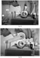
- the priming of the cartridge 19 allows the filling of the tubular extension 23 and the nozzle 24 with paste by moving the piston 18 until the paste 26 begins to be extruded through the nozzle 24, as shown in there Figure 15 .
- the table 9a is then moved along the axis Figure 16 .
- the table 9b is then moved along the Y axis by means of the motor 12 so as to cause the nozzle 24 for extruding the dough to penetrate the initial point of deposition in the channel of the tube 1, as shown in the figure. Figure 17 .
- the tube 1 is then rotated by means of the motor 8, and the deposition phase is then initiated by simultaneously actuating the motor 12 causing the movement of the tube 1 along the Y axis and of the motor 17 causing the advancement of the piston 18 of the cartridge 19.
- the conjunction of the actions generated by each of the three motors 8, 12 and 17 leads to a helical deposition of paste 27 on the internal surface of the tube as shown on the figures 8 , 18 and 19 .
- the tables 9a and 9b are returned to their initial position and the tube is removed from the device.
- Table 5 can be used for implementing the device as described above.
- Table 5 Tube Dimensions ⁇ int 28.5 mm / Lg Ht: 126 mm Dough density 1.2 g/cm 3 Cartridge size Internal ⁇ : 20.2 mm / Useful length: 78 mm Nozzle diameter ⁇ 6mm Nozzle tilt 235° (or 8h) Speed [Mrot_tube] 2 rpm Speed [My_tube] 14mm/min Speed [My_piston] 7mm/min Linear mass of paste deposited 16.5 g/mL Pattern length 1000mm
- the device of the invention is useful for depositing patterns of pastes inside a tube, and more particularly for obtaining ignition tubes for propellant charges. It can also be used for any application requiring the deposition of patterns in a tube, for example, in the industrial, pharmaceutical or food sector.
Landscapes
- Engineering & Computer Science (AREA)
- General Engineering & Computer Science (AREA)
- Manufacturing & Machinery (AREA)
- Chemical & Material Sciences (AREA)
- Combustion & Propulsion (AREA)
- Organic Chemistry (AREA)
- Life Sciences & Earth Sciences (AREA)
- Wood Science & Technology (AREA)
- Coating Apparatus (AREA)
- Tubes (AREA)
Claims (8)
- Vorrichtung zum Aufbringen von Pastenmustern, insbesondere einer Zündladung, auf die Oberfläche des Kanals eines Rohrs (1), insbesondere eines brennbaren Rohrs, wobei die Vorrichtung einen Rahmen umfasst, der eine erste mechanische Einheit A zum Halten, Positionieren und Bewegen des Rohrs und eine zweite mechanische Einheit B zum Extrudieren von Paste zum Aufbringen der Pastenmuster trägt, wobei die Einheiten A und B miteinander zusammenwirken,
dadurch gekennzeichnet, dass die Einheit A:- einen ersten Tisch (9a) umfasst, der auf einem zweiten Tisch (9b) montiert ist, wobei diese beiden Tische die Bewegung entlang einer horizontalen Achse Y, die entlang der Mittelachse des Rohrs angeordnet ist, und entlang einer Achse X, die in horizontaler Richtung orthogonal zur Achse Y angeordnet ist, ermöglichen, und- auf dem ersten Tisch (9a) ein System (28) zum Halten und Drehen des Rohrs entlang einer Drehachse Z eingebaut ist - Vorrichtung nach Anspruch 1, wobei der erste Tisch (9a) umfasst:- ein Rohr (1), das zwischen drei Rollen (2a, 2b, 3) positioniert ist, die auf dem ersten Tisch (9a) befestigt sind, wobei eine erste und eine zweite Rolle (2a, 2b) jeweils an einem Ende eine kreisförmige Schulter (5) aufweisen, die es ermöglicht, das Rohr (1) entlang der Achse Y in Position zu halten, und am anderen Ende ein Zahnrad (6a, 6b);- einen Motor (8), der es ermöglicht, die erste und die zweite Rolle (2a, 2b) über eine Achse zu drehen, die mit einem Zahnrad (7) gekoppelt ist, das mit den Zahnrädern (6a, 6b) zusammenwirkt.
- Vorrichtung nach Anspruch 2, wobei eine dritte Rolle (3) mit Mitteln versehen ist, die es ermöglichen, sie auszurücken, um das Rohr (1) auf der ersten und zweiten Rolle (2a, 2b) zu positionieren und es dann über dem Rohr (1) zusammenzufalten.
- Vorrichtung nach einem der Ansprüche 1 bis 3, wobei der zweite Tisch (9b) auf dem Rahmen (C) befestigt ist, wobei der erste Tisch (9a) auf dem zweiten Tisch (9b) so montiert ist, dass eine Bewegung des ersten Tisches (9a) entlang der Achse X relativ zum zweiten Tisch (9b) und eine Bewegung des zweiten Tisches (9b) entlang der Achse Y relativ zum Rahmen (C) möglich ist.
- Vorrichtung nach einem der Ansprüche 1 bis 4, wobei die Einheit B umfasst:- einen festen Tisch (13), der zwei Ringe (14a) und (14b) trägt, die auf Führungsschienen gleiten, die mit der Achse Y kolinear sind;- einen Schlitten (15), der von einer Schnecke (16) bewegt wird, die von einem Motor (17) angetrieben wird;- eine Kartusche (19) mit einem Kolben (18), der mit einer Pleuelstange (20), einer rohrförmigen Verlängerung (23) und einer Düse (24) versehen ist.
- Vorrichtung nach Anspruch 5, wobei die Kartusche eine Spritze ist, und wobei:- die Stange (20) und der Kolben (18) ein einziges Stück bilden;- der Stößel des Kolbens (18) der Spritze in einer zentralen Kammer (21) des Schlittens (15) untergebracht ist, die mit einer Klammer versehen ist;- der Körper der Spritze wird von einer Wiege (22) gehalten;- die zentrale Kammer (21) und die Wiege (22) sind so ausgerichtet und angeordnet, dass die Achse der Spritze Yc kolinear mit der Achse Y ist.
- Vorrichtung nach Anspruch 5, wobei die Kartusche ein zylindrischer Körper ist, der mit einem Kolben ausgestattet ist, und wobei:- die Stange (20) mittig an dem Kolben (18) befestigt ist;- die Stange (20) an ihrem anderen Ende durch eine Klammer in einer zentralen Kammer (21) des Schlittens (15) gehalten wird;- ein erster und ein zweiter Schenkel (25a, 25b) sind einander gegenüberliegend auf dem festen Tisch (13) befestigt, wobei der erste Schenkel (25a) eine Bohrung mit einer Gegenbohrung und der zweite Schenkel (25b) eine Halbbohrung mit einer Schulter aufweist, um die beiden Enden der Kartusche aufzunehmen;- die Schenkel (25a) und (25b) und die zentrale Kammer (21) so ausgerichtet und angeordnet sind, dass die Achse der Kartusche Yc kolinear mit der Achse Y ist.
- Verfahren zum Aufbringen von Pastenmustern, insbesondere einer Zündladung, auf die Oberfläche des Kanals eines Rohres (1), insbesondere eines brennbaren Rohres, durch Anwendung der Vorrichtung nach einem der Ansprüche 1 bis 7.
Applications Claiming Priority (2)
| Application Number | Priority Date | Filing Date | Title |
|---|---|---|---|
| FR2000429A FR3106400A1 (fr) | 2020-01-17 | 2020-01-17 | Dispositif pour deposer des motifs pateux dans un tube |
| PCT/FR2021/050067 WO2021144539A1 (fr) | 2020-01-17 | 2021-01-14 | Dispositif pour deposer des motifs pateux dans un tube |
Publications (3)
| Publication Number | Publication Date |
|---|---|
| EP4090909A1 EP4090909A1 (de) | 2022-11-23 |
| EP4090909C0 EP4090909C0 (de) | 2024-02-21 |
| EP4090909B1 true EP4090909B1 (de) | 2024-02-21 |
Family
ID=72088182
Family Applications (1)
| Application Number | Title | Priority Date | Filing Date |
|---|---|---|---|
| EP21719696.3A Active EP4090909B1 (de) | 2020-01-17 | 2021-01-14 | Vorrichtung zum verlegen von pastenmustern in einem rohr |
Country Status (9)
| Country | Link |
|---|---|
| US (1) | US12038263B2 (de) |
| EP (1) | EP4090909B1 (de) |
| KR (1) | KR20230005114A (de) |
| ES (1) | ES2987580T3 (de) |
| FR (1) | FR3106400A1 (de) |
| IL (1) | IL294748B1 (de) |
| PL (1) | PL4090909T3 (de) |
| WO (1) | WO2021144539A1 (de) |
| ZA (1) | ZA202208594B (de) |
Families Citing this family (2)
| Publication number | Priority date | Publication date | Assignee | Title |
|---|---|---|---|---|
| FR3132712A1 (fr) | 2022-02-15 | 2023-08-18 | Eurenco | Procédé d'obtention de pâtes d'allumage en mélangeur à résonance acoustique |
| FR3139818B1 (fr) * | 2022-09-21 | 2025-06-20 | Eurenco France | Chargements combustibles adhérant à la paroi interne d'une structure combustible contenant un chargement propulsif |
Family Cites Families (8)
| Publication number | Priority date | Publication date | Assignee | Title |
|---|---|---|---|---|
| US3182595A (en) * | 1962-07-20 | 1965-05-11 | Harry F Hassmann | Igniter assembly containing strands of benite |
| US3453163A (en) * | 1967-10-10 | 1969-07-01 | Stone Straw Corp | Method of making helically wound bodies having plastic material extruded on their inner walls |
| FR2593905B1 (fr) | 1986-02-03 | 1990-05-25 | France Etat Armement | Allumeur destructible pour charges propulsives |
| DE3740986A1 (de) * | 1987-12-03 | 1988-06-30 | Bongers Hermann | Treibladungsanzuender mit variabler anfeuerungscharakteristik |
| FR2725781B1 (fr) | 1994-10-18 | 1997-01-24 | Giat Ind Sa | Materiau d'allumage pour charge propulsive et systeme d'allumage ou tube allumeur mettant en oeuvre un tel materiau |
| FR2737002B1 (fr) * | 1995-07-20 | 1997-08-29 | Giat Ind Sa | Systeme d'allumage d'une charge propulsive, notamment pour munition d'artillerie de campagne, et son procede de fabrication |
| DE10328450A1 (de) * | 2003-06-25 | 2005-01-20 | Rheinmetall W & M Gmbh | Verfahren zur Beseitigung von Beschichtungs- und/oder Erosionsschäden |
| US20190351484A1 (en) * | 2018-05-20 | 2019-11-21 | 3D Flexible, Inc. | Metal pastes for additive manufacturing |
-
2020
- 2020-01-17 FR FR2000429A patent/FR3106400A1/fr active Pending
-
2021
- 2021-01-13 IL IL294748A patent/IL294748B1/en unknown
- 2021-01-14 EP EP21719696.3A patent/EP4090909B1/de active Active
- 2021-01-14 ES ES21719696T patent/ES2987580T3/es active Active
- 2021-01-14 US US17/793,473 patent/US12038263B2/en active Active
- 2021-01-14 WO PCT/FR2021/050067 patent/WO2021144539A1/fr not_active Ceased
- 2021-01-14 PL PL21719696.3T patent/PL4090909T3/pl unknown
- 2021-01-14 KR KR1020227027262A patent/KR20230005114A/ko active Pending
-
2022
- 2022-08-01 ZA ZA2022/08594A patent/ZA202208594B/en unknown
Also Published As
| Publication number | Publication date |
|---|---|
| EP4090909C0 (de) | 2024-02-21 |
| EP4090909A1 (de) | 2022-11-23 |
| WO2021144539A1 (fr) | 2021-07-22 |
| IL294748B1 (en) | 2025-10-01 |
| KR20230005114A (ko) | 2023-01-09 |
| ZA202208594B (en) | 2024-01-31 |
| PL4090909T3 (pl) | 2024-11-18 |
| US12038263B2 (en) | 2024-07-16 |
| IL294748A (en) | 2022-09-01 |
| US20230064872A1 (en) | 2023-03-02 |
| FR3106400A1 (fr) | 2021-07-23 |
| ES2987580T3 (es) | 2024-11-15 |
Similar Documents
| Publication | Publication Date | Title |
|---|---|---|
| EP4090909B1 (de) | Vorrichtung zum verlegen von pastenmustern in einem rohr | |
| FR2489419A1 (fr) | Grain de generateur de gaz et son procede de fabrication | |
| FR2776656A1 (fr) | Procede de fabrication d'un objet a partir d'un materiau granulaire, tube allumeur et charge propulsive obtenus avec un tel procede | |
| CA2418319C (fr) | Procede bicomposant semi-continu d'obtention d'un chargement explosif composite a matrice polyurethanne | |
| EP4090644B1 (de) | Anzündrohr für eine treibladung | |
| FR2472578A1 (fr) | Composition de nitrocellulose et procede pour sa production | |
| EP3212594B1 (de) | Effizientes pyrotechnisches verbundprodukt ohne blei in der zusammensetzung und herstellung davon | |
| EP3887752A1 (de) | Zündladung für munition, verfahren zu deren herstellung, zünderrohr und zündsystem mit einer solchen ladung | |
| WO2022129771A1 (fr) | Procede d'obtention de structures a base de nitrocellulose par fabrication additive | |
| FR2893613A1 (fr) | Procede bicomposant semi-continu perfectionne d'obtention d'un chargement explosif composite a matrice polyurethanne | |
| EP0808813B1 (de) | Kontinuierliches Verfahren zur lösungsmittelfreien Herstellung von Zusammensetzungen für Pyrotechnische Erzeugnisse mit wärmehärtbarem Bindemittel | |
| EP3969432B1 (de) | Treibladungspulverkorn mit mindestens teilweise verschlossenen kanälen | |
| EP3476821B1 (de) | Herstellungsverfahren eines pyrotechnischen verbundprodukts | |
| EP1333016A2 (de) | Semikontinuierliches Giessverfahren für feste Treibstoffpasten durch Verwendung von zwei Komponenten | |
| FR3139818A1 (fr) | Chargements combustibles adhérant à la paroi interne d'une structure combustible contenant un chargement propulsif | |
| EP4479364A1 (de) | Verfahren zur herstellung von brennpasten in einem akustischen resonanzmischer | |
| FR2623796A1 (fr) | Procede de fabrication d'elements de poudre propulsive bi-composition contenant de la nitrocellulose et elements de poudre ainsi obtenus | |
| EP1741690A2 (de) | Verfahren und Vorrichtung zum kontinuierlichen Herstellen von pyrotechnischen Gegenständen | |
| EP1767574A1 (de) | Verfahren zur Herstellung energetischer Zusammensetzungen umfassend in einer organischen Matrize dispergierte Nanopartikel aus einem chemischen Element oder einer Chemikalie | |
| CA2968255A1 (fr) | Produits explosifs composites de faible epaisseur et leur preparation | |
| BE896878A (fr) | Fabrication de compositions propulsives et de charges propulsives. |
Legal Events
| Date | Code | Title | Description |
|---|---|---|---|
| STAA | Information on the status of an ep patent application or granted ep patent |
Free format text: STATUS: UNKNOWN |
|
| STAA | Information on the status of an ep patent application or granted ep patent |
Free format text: STATUS: THE INTERNATIONAL PUBLICATION HAS BEEN MADE |
|
| PUAI | Public reference made under article 153(3) epc to a published international application that has entered the european phase |
Free format text: ORIGINAL CODE: 0009012 |
|
| STAA | Information on the status of an ep patent application or granted ep patent |
Free format text: STATUS: REQUEST FOR EXAMINATION WAS MADE |
|
| 17P | Request for examination filed |
Effective date: 20220715 |
|
| AK | Designated contracting states |
Kind code of ref document: A1 Designated state(s): AL AT BE BG CH CY CZ DE DK EE ES FI FR GB GR HR HU IE IS IT LI LT LU LV MC MK MT NL NO PL PT RO RS SE SI SK SM TR |
|
| DAV | Request for validation of the european patent (deleted) | ||
| DAX | Request for extension of the european patent (deleted) | ||
| GRAP | Despatch of communication of intention to grant a patent |
Free format text: ORIGINAL CODE: EPIDOSNIGR1 |
|
| STAA | Information on the status of an ep patent application or granted ep patent |
Free format text: STATUS: GRANT OF PATENT IS INTENDED |
|
| INTG | Intention to grant announced |
Effective date: 20230803 |
|
| GRAS | Grant fee paid |
Free format text: ORIGINAL CODE: EPIDOSNIGR3 |
|
| GRAA | (expected) grant |
Free format text: ORIGINAL CODE: 0009210 |
|
| STAA | Information on the status of an ep patent application or granted ep patent |
Free format text: STATUS: THE PATENT HAS BEEN GRANTED |
|
| AK | Designated contracting states |
Kind code of ref document: B1 Designated state(s): AL AT BE BG CH CY CZ DE DK EE ES FI FR GB GR HR HU IE IS IT LI LT LU LV MC MK MT NL NO PL PT RO RS SE SI SK SM TR |
|
| REG | Reference to a national code |
Ref country code: GB Ref legal event code: FG4D Free format text: NOT ENGLISH |
|
| REG | Reference to a national code |
Ref country code: CH Ref legal event code: EP |
|
| REG | Reference to a national code |
Ref country code: IE Ref legal event code: FG4D Free format text: LANGUAGE OF EP DOCUMENT: FRENCH |
|
| REG | Reference to a national code |
Ref country code: DE Ref legal event code: R096 Ref document number: 602021009636 Country of ref document: DE |
|
| U01 | Request for unitary effect filed |
Effective date: 20240319 |
|
| U07 | Unitary effect registered |
Designated state(s): AT BE BG DE DK EE FI FR IT LT LU LV MT NL PT SE SI Effective date: 20240326 |
|
| REG | Reference to a national code |
Ref country code: CH Ref legal event code: PK Free format text: DIE PUBLIKATION VOM 17.04.2024 WURDE AM 24.04.2024 IRRTUEMLICHERWEISE ERNEUT PUBLIZIERT. LA PUBLICATION DU 17.04.2024 A ETE REPUBLIEE PAR ERREUR LE 24.04.2024. LA PUBBLICAZIONE DEL 17.04.2024 E STATA ERRONEAMENTE RIPUBBLICATA IL 24.04.2024. |
|
| RAP4 | Party data changed (patent owner data changed or rights of a patent transferred) |
Owner name: EURENCO FRANCE SAS |
|
| U1H | Name or address of the proprietor changed after the registration of the unitary effect |
Owner name: EURENCO FRANCE SAS; FR |
|
| PG25 | Lapsed in a contracting state [announced via postgrant information from national office to epo] |
Ref country code: IS Free format text: LAPSE BECAUSE OF FAILURE TO SUBMIT A TRANSLATION OF THE DESCRIPTION OR TO PAY THE FEE WITHIN THE PRESCRIBED TIME-LIMIT Effective date: 20240621 |
|
| PG25 | Lapsed in a contracting state [announced via postgrant information from national office to epo] |
Ref country code: GR Free format text: LAPSE BECAUSE OF FAILURE TO SUBMIT A TRANSLATION OF THE DESCRIPTION OR TO PAY THE FEE WITHIN THE PRESCRIBED TIME-LIMIT Effective date: 20240522 |
|
| PG25 | Lapsed in a contracting state [announced via postgrant information from national office to epo] |
Ref country code: RS Free format text: LAPSE BECAUSE OF FAILURE TO SUBMIT A TRANSLATION OF THE DESCRIPTION OR TO PAY THE FEE WITHIN THE PRESCRIBED TIME-LIMIT Effective date: 20240521 Ref country code: HR Free format text: LAPSE BECAUSE OF FAILURE TO SUBMIT A TRANSLATION OF THE DESCRIPTION OR TO PAY THE FEE WITHIN THE PRESCRIBED TIME-LIMIT Effective date: 20240221 |
|
| REG | Reference to a national code |
Ref country code: SK Ref legal event code: T3 Ref document number: E 44162 Country of ref document: SK |
|
| PG25 | Lapsed in a contracting state [announced via postgrant information from national office to epo] |
Ref country code: RS Free format text: LAPSE BECAUSE OF FAILURE TO SUBMIT A TRANSLATION OF THE DESCRIPTION OR TO PAY THE FEE WITHIN THE PRESCRIBED TIME-LIMIT Effective date: 20240521 Ref country code: IS Free format text: LAPSE BECAUSE OF FAILURE TO SUBMIT A TRANSLATION OF THE DESCRIPTION OR TO PAY THE FEE WITHIN THE PRESCRIBED TIME-LIMIT Effective date: 20240621 Ref country code: HR Free format text: LAPSE BECAUSE OF FAILURE TO SUBMIT A TRANSLATION OF THE DESCRIPTION OR TO PAY THE FEE WITHIN THE PRESCRIBED TIME-LIMIT Effective date: 20240221 Ref country code: GR Free format text: LAPSE BECAUSE OF FAILURE TO SUBMIT A TRANSLATION OF THE DESCRIPTION OR TO PAY THE FEE WITHIN THE PRESCRIBED TIME-LIMIT Effective date: 20240522 |
|
| PG25 | Lapsed in a contracting state [announced via postgrant information from national office to epo] |
Ref country code: SM Free format text: LAPSE BECAUSE OF FAILURE TO SUBMIT A TRANSLATION OF THE DESCRIPTION OR TO PAY THE FEE WITHIN THE PRESCRIBED TIME-LIMIT Effective date: 20240221 |
|
| PG25 | Lapsed in a contracting state [announced via postgrant information from national office to epo] |
Ref country code: SM Free format text: LAPSE BECAUSE OF FAILURE TO SUBMIT A TRANSLATION OF THE DESCRIPTION OR TO PAY THE FEE WITHIN THE PRESCRIBED TIME-LIMIT Effective date: 20240221 Ref country code: RO Free format text: LAPSE BECAUSE OF FAILURE TO SUBMIT A TRANSLATION OF THE DESCRIPTION OR TO PAY THE FEE WITHIN THE PRESCRIBED TIME-LIMIT Effective date: 20240221 |
|
| REG | Reference to a national code |
Ref country code: ES Ref legal event code: FG2A Ref document number: 2987580 Country of ref document: ES Kind code of ref document: T3 Effective date: 20241115 |
|
| REG | Reference to a national code |
Ref country code: DE Ref legal event code: R097 Ref document number: 602021009636 Country of ref document: DE |
|
| PLBE | No opposition filed within time limit |
Free format text: ORIGINAL CODE: 0009261 |
|
| STAA | Information on the status of an ep patent application or granted ep patent |
Free format text: STATUS: NO OPPOSITION FILED WITHIN TIME LIMIT |
|
| PGFP | Annual fee paid to national office [announced via postgrant information from national office to epo] |
Ref country code: NO Payment date: 20241227 Year of fee payment: 5 |
|
| PGFP | Annual fee paid to national office [announced via postgrant information from national office to epo] |
Ref country code: PL Payment date: 20241209 Year of fee payment: 5 |
|
| PGFP | Annual fee paid to national office [announced via postgrant information from national office to epo] |
Ref country code: CZ Payment date: 20241211 Year of fee payment: 5 |
|
| PGFP | Annual fee paid to national office [announced via postgrant information from national office to epo] |
Ref country code: SK Payment date: 20241211 Year of fee payment: 5 |
|
| 26N | No opposition filed |
Effective date: 20241122 |
|
| U20 | Renewal fee for the european patent with unitary effect paid |
Year of fee payment: 5 Effective date: 20250117 |
|
| PGFP | Annual fee paid to national office [announced via postgrant information from national office to epo] |
Ref country code: ES Payment date: 20250213 Year of fee payment: 5 |
|
| REG | Reference to a national code |
Ref country code: CH Ref legal event code: PL |
|
| PG25 | Lapsed in a contracting state [announced via postgrant information from national office to epo] |
Ref country code: MC Free format text: LAPSE BECAUSE OF FAILURE TO SUBMIT A TRANSLATION OF THE DESCRIPTION OR TO PAY THE FEE WITHIN THE PRESCRIBED TIME-LIMIT Effective date: 20240221 |
|
| GBPC | Gb: european patent ceased through non-payment of renewal fee |
Effective date: 20250114 |
|
| PG25 | Lapsed in a contracting state [announced via postgrant information from national office to epo] |
Ref country code: GB Free format text: LAPSE BECAUSE OF NON-PAYMENT OF DUE FEES Effective date: 20250114 |
|
| PG25 | Lapsed in a contracting state [announced via postgrant information from national office to epo] |
Ref country code: CH Free format text: LAPSE BECAUSE OF NON-PAYMENT OF DUE FEES Effective date: 20250131 |