EP4089882B1 - Verdichtungsplatte, zugehörige magnetische masse, stator, rotor, rotierende elektrische maschine und antriebssystem - Google Patents
Verdichtungsplatte, zugehörige magnetische masse, stator, rotor, rotierende elektrische maschine und antriebssystem Download PDFInfo
- Publication number
- EP4089882B1 EP4089882B1 EP21305635.1A EP21305635A EP4089882B1 EP 4089882 B1 EP4089882 B1 EP 4089882B1 EP 21305635 A EP21305635 A EP 21305635A EP 4089882 B1 EP4089882 B1 EP 4089882B1
- Authority
- EP
- European Patent Office
- Prior art keywords
- compaction
- laminated magnetic
- magnetic
- laminated
- electric machine
- Prior art date
- Legal status (The legal status is an assumption and is not a legal conclusion. Google has not performed a legal analysis and makes no representation as to the accuracy of the status listed.)
- Active
Links
Images


Classifications
-
- H—ELECTRICITY
- H02—GENERATION; CONVERSION OR DISTRIBUTION OF ELECTRIC POWER
- H02K—DYNAMO-ELECTRIC MACHINES
- H02K1/00—Details of the magnetic circuit
- H02K1/06—Details of the magnetic circuit characterised by the shape, form or construction
- H02K1/22—Rotating parts of the magnetic circuit
- H02K1/28—Means for mounting or fastening rotating magnetic parts on to, or to, the rotor structures
-
- H—ELECTRICITY
- H02—GENERATION; CONVERSION OR DISTRIBUTION OF ELECTRIC POWER
- H02K—DYNAMO-ELECTRIC MACHINES
- H02K1/00—Details of the magnetic circuit
- H02K1/06—Details of the magnetic circuit characterised by the shape, form or construction
- H02K1/12—Stationary parts of the magnetic circuit
-
- H—ELECTRICITY
- H02—GENERATION; CONVERSION OR DISTRIBUTION OF ELECTRIC POWER
- H02K—DYNAMO-ELECTRIC MACHINES
- H02K1/00—Details of the magnetic circuit
- H02K1/06—Details of the magnetic circuit characterised by the shape, form or construction
- H02K1/12—Stationary parts of the magnetic circuit
- H02K1/16—Stator cores with slots for windings
-
- H—ELECTRICITY
- H02—GENERATION; CONVERSION OR DISTRIBUTION OF ELECTRIC POWER
- H02K—DYNAMO-ELECTRIC MACHINES
- H02K1/00—Details of the magnetic circuit
- H02K1/06—Details of the magnetic circuit characterised by the shape, form or construction
- H02K1/12—Stationary parts of the magnetic circuit
- H02K1/18—Means for mounting or fastening magnetic stationary parts on to, or to, the stator structures
-
- H—ELECTRICITY
- H02—GENERATION; CONVERSION OR DISTRIBUTION OF ELECTRIC POWER
- H02K—DYNAMO-ELECTRIC MACHINES
- H02K1/00—Details of the magnetic circuit
- H02K1/06—Details of the magnetic circuit characterised by the shape, form or construction
- H02K1/12—Stationary parts of the magnetic circuit
- H02K1/20—Stationary parts of the magnetic circuit with channels or ducts for flow of cooling medium
-
- H—ELECTRICITY
- H02—GENERATION; CONVERSION OR DISTRIBUTION OF ELECTRIC POWER
- H02K—DYNAMO-ELECTRIC MACHINES
- H02K1/00—Details of the magnetic circuit
- H02K1/06—Details of the magnetic circuit characterised by the shape, form or construction
- H02K1/22—Rotating parts of the magnetic circuit
-
- H—ELECTRICITY
- H02—GENERATION; CONVERSION OR DISTRIBUTION OF ELECTRIC POWER
- H02K—DYNAMO-ELECTRIC MACHINES
- H02K1/00—Details of the magnetic circuit
- H02K1/06—Details of the magnetic circuit characterised by the shape, form or construction
- H02K1/22—Rotating parts of the magnetic circuit
- H02K1/26—Rotor cores with slots for windings
-
- H—ELECTRICITY
- H02—GENERATION; CONVERSION OR DISTRIBUTION OF ELECTRIC POWER
- H02K—DYNAMO-ELECTRIC MACHINES
- H02K11/00—Structural association of dynamo-electric machines with electric components or with devices for shielding, monitoring or protection
- H02K11/0094—Structural association with other electrical or electronic devices
-
- H—ELECTRICITY
- H02—GENERATION; CONVERSION OR DISTRIBUTION OF ELECTRIC POWER
- H02K—DYNAMO-ELECTRIC MACHINES
- H02K11/00—Structural association of dynamo-electric machines with electric components or with devices for shielding, monitoring or protection
- H02K11/30—Structural association with control circuits or drive circuits
- H02K11/33—Drive circuits, e.g. power electronics
-
- H—ELECTRICITY
- H02—GENERATION; CONVERSION OR DISTRIBUTION OF ELECTRIC POWER
- H02K—DYNAMO-ELECTRIC MACHINES
- H02K17/00—Asynchronous induction motors; Asynchronous induction generators
- H02K17/02—Asynchronous induction motors
Definitions
- the present invention concerns rotary electric machines and relates more particularly to a compaction plate for compacting laminated magnetic sheet of a magnetic mass.
- the present invention also relates to a rotor and a stator comprising such a compaction plate, and a rotary electric machine comprising such a rotor and/or a stator.
- a rotor or a stator for an electric machine comprises a magnetic mass made of a plurality of magnetic sheets compacted between two clamping plates connected by tie rods, each compaction plate being a massive plate with a central hole made of steel.
- the clamping plates do not contribute to the performances of the machine.
- the compaction plates are made of steel, they increase the mass of the rotating electric machine, in particular the mass of a rotor comprising the clamping plates deteriorating the performances of the electric machine.
- a high frequency power supply signal of the rotating electric machine generates parasitic harmonics during the power conversion of the high frequency power supply signal by a variable frequency power signal.
- the parasitic harmonics may also be generated by electromagnetic parts, for example rotor and /or stator slots, of the rotating electric machine supplied with a constant high frequency power supply signal.
- the frequencies of the parasitic harmonics of the power supply signal may be for example frequencies more than a fundamental supply frequency equal to the pair of electric poles multiplied by the spinning frequency of the rotor.
- electromagnetic shields are implemented at each end of the magnetic mass.
- Document JP2014036485 discloses a rotor comprising a laminated core formed by laminating magnetic thin plates and comprising a plurality of magnets arranged in holes of the laminated core. Each end of the laminated core comprises a resin molded plate fixing the magnets in each hole.
- the resin molded plates do not warm up under the effect of a magnetic field.
- the molded plates are not rigid enough to maintain the magnetic mass compacted.
- a compaction plate for magnetic mass comprising a plurality of laminated magnetic sheets, the laminated magnetic sheets being fixed together with fixing and electric insulating means.
- Each laminated magnetic sheet is formed by a plurality of segmented laminated magnetic sheets.
- the fixing and electric insulating means comprise glue disposed between two adjacent laminated magnetic sheets.
- the fixing and electric insulating means comprise an electric insulating resin and at least one boss on each laminated magnetic sheet, each boss comprising a first face forming a cavity and a second face projecting from the magnetic sheet opposite the first face, the electric insulating resin being disposed between two adjacent laminated sheet, the first face of one laminated magnetic sheet being inserted into the second face of a first adjacent laminated magnetic sheet and the second face of the one laminated magnetic sheet being inserted into the first face of a second adjacent laminated magnetic sheet.
- each laminated magnetic sheet comprises at least one tooth comprising notches intended to accommodate electrical windings.
- the magnetic mass comprises a plurality of laminated magnetic sheets compacted between two compaction elements, a first compaction element comprising a compaction plate as defined below, the compaction elements being connected by connecting means.
- the second compaction element comprises a compaction plate as defined below.
- the connecting means comprise tie rods in the magnetic mass, the tie rods maintaining the laminated magnetic sheets compacted between the two compaction elements.
- the connecting means comprise retaining bars maintaining the laminated magnetic sheets compacted between the two compaction elements.
- the magnetic mass comprises spacers arranged between two successive bundles of laminated magnetic sheets forming ventilation channels.
- Another object of the invention relates to a driving system comprising a rotating electric machine as defined below and a power supply feeding the electric machine with a variable frequency power signal, for example with a high frequency power signal more than 100 Hz.
- Figure 1 illustrates an embodiment of a driving system 1 comprising a rotating electric machine 2 and a power supply 3 feeding the rotating electric machine 2.
- the rotating electric machine 2 comprises a stator 4 and a rotor 5 logged in the stator 4.
- A1 is an axis of revolution of the rotor 5 in the stator 4.
- the power of the rotating electric machine 2 is more than 100 KW, for example 1 MW.
- the power supply 3 may supply a high frequency power signal, the frequency being for example more than the spinning frequency of the rotor equal to the fundamental supply frequency divided by the pair of electric poles of the rotating electric machine 2.
- the power supply 3 may supply a variable frequency power signal.
- Figure 2 illustrates a half-section of the cylindrical stator 4 of the rotating electric machine 2.
- the stator 4 is intended to receive the rotor 5 in its central space comprising an axis of revolution A1.
- the stator 4 includes a magnetic mass 6 comprising packs of laminated magnetic sheets 7 compressed between two compaction elements 8, 9 arranged on either side of the stator 4 and connected by connecting means comprising retaining bars 10 maintaining the laminated magnetic sheets compacted between the two compaction elements 8, 9, the retaining bars 10 being evenly distributed as represented here on an outer periphery of the laminated magnetic sheets 7, according to the axial direction A1, and a chassis 11 encompassing the magnetic mass 6.
- connecting means comprise tie rods evenly distributed on a diameter of the laminated magnetic sheets 7.
- Two adjacent laminated magnetic sheets 7 may be separated by spacers 12 to create a ventilation channels as shown here.
- the magnetic mass 6 does not comprise spacers 12.
- the stator 4 further comprises electrical windings 14.
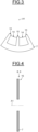
- Figure 3 illustrates a partial section of a laminated magnetic sheet 7 accommodating electrical windings 14 generating magnetic flux.
- the laminated magnetic sheet 7 comprises teeth 15 comprising notches accommodating the electrical windings 14.
- Figure 4 illustrates a section of an embodiment, not according to the invention, of the compaction elements 8, 9.
- Each compaction element 8, 9 comprises a compaction plate 16 including a plurality of laminated magnetic sheets 7, the laminated magnetic sheets being fixed together with fixing and electric insulating means.
- the laminated magnetic sheets 7 are made of magnetic steel.
- the number of laminated magnetic sheets 7 forming the compaction plate 16 is chosen so that the compaction elements 8, 9 are rigid enough to maintain compacted the magnetic mass 6.
- the fixing and electric insulating means comprise varnish on a first side of first laminated magnetic sheet 7 and glue on a second side of a second laminated magnetic sheet 7, the first and second sides being in contact.
- Figure 5 illustrates a section of an embodiment, according to the invention, of the compaction plate 16 in which the fixing and electric insulating means comprise an electric insulating resin (strong line) and bosses 17.
- the fixing and electric insulating means comprise an electric insulating resin (strong line) and bosses 17.
- Each laminated magnetic sheet 7 comprises at least one boss 17 comprising a first face 18 forming a cavity and a second face 19 projecting from the magnetic sheet opposite the first face.
- the electric insulating resin is disposed between two adjacent laminated sheet 7.
- the compaction elements 8, 9 are not identical, a first compaction element 8 comprises the compaction plate 16 and the second compaction element 9 comprises a clamping plate.
- Figure 6 illustrates an axial section of an embodiment of the rotor 5.
- the rotor 6 comprises a cylindrical magnetic mass 20 clamped between two compaction elements 21, 22, short-circuit rings 23 in contact with the face of the compaction elements 21, 22 opposite to the face in contact with the magnetic mass 20.
- short-circuit rings 23 are replaced by short disks.
- the magnetic mass 20 comprises packs of laminated magnetic sheets 24 compressed between the two compaction elements 21, 22 arranged on either side of the magnetic mass 20 and connected by connecting means comprising tie rods 25 maintaining the laminated magnetic sheets 24 compacted, the tie rods 25 being evenly distributed as represented here on an outer periphery of the laminated magnetic sheets 24, according to the axial direction A1.
- the magnetic mass 20, the compaction elements 21, 22 and the short-circuit rings 23 are crossed by a shaft 26.
- Conductor bars 27 are housed in housings of the magnetic mass 20 and evenly distributed over a diameter of the magnetic mass 20 so that the shorting rings 23 and the conductor bars 27 form a squirrel cage.
- the short-circuit rings 23 and the conductive bars 27 are made, for example, of copper or of alloyed copper.
- the two compaction elements 21, 22 are identical, each comprising a compaction plate made of laminated magnetic sheets 24 fixed together with fixing and electric insulating means in the same way as explained above.
- a first compaction element 21 comprises the compaction plate and the second compaction element 22 comprises a clamping plate.
- the rotating electric machine 2 implementing the rotor 5 is of the squirrel cage asynchronous type.
- the rotor 5 may comprise windings replacing the conductive bars 27, the windings and the short-circuit rings 23 forming a squirrel cage.
- the removal and the replacement of the clamping plates by laminated magnetic sheets 24 permits to decrease the mass of the rotating electric machine 2 and to increase the active part generating magnetic flux of the magnetic mass 6, 20 improving the efficiency of the rotating electric machine 2 for example by improving the generated torque on the rotor 5 in motor mode, without increasing the volume of the magnetic mass 6, 20 and thus the volume of the rotating electric machine 2, or for example for defined characteristics of a rotating electric rotating electric machine, by reducing the mass and the volume of the machine.
- the removal and the replacement of the clamping plates by laminated magnetic sheets 24 permits to suppress the electromagnetic shields decreasing even more the mass of the rotating electric machine 2, for example the magnetic mass of the rotor to improve even more the torque generated by the rotating electric machine in motor mode and without warming up the rotor and/or the stator with parasitic harmonics so that the rotating electric machine 2 is even more efficient for example by improving the generated torque on the rotor 5 in motor or generator modes.
- each laminated magnetic sheet 7, 24 is formed by a plurality of segmented laminated magnetic sheets.
Landscapes
- Engineering & Computer Science (AREA)
- Power Engineering (AREA)
- Microelectronics & Electronic Packaging (AREA)
- Iron Core Of Rotating Electric Machines (AREA)
- Manufacture Of Motors, Generators (AREA)
Claims (13)
- Verdichtungsplatte (8, 9, 21, 22) für Magnetmasse (6, 15), wobei die Verdichtungsplatte eine Vielzahl von laminierten Magnetbahnen (7, 24) umfasst, und Befestigungs- und elektrische Isoliermittel, die ein elektrisch isolierendes Harz und mindestens einen Ansatz(17) auf jeder laminierten Magnetbahn umfassen, jeder Ansatz, der eine erste Fläche umfasst, die einen Hohlraum (18) bildet, und eine zweite Fläche (19), die aus der der ersten Fläche gegenüberliegenden Magnetbahn herausragt, wobei das elektrische isolierende Harz zwischen zwei benachbarten laminierten Bahnen angeordnet ist, die erste Fläche einer laminierten Magnetbahn in die zweite Fläche einer ersten benachbarten laminierten Magnetbahn eingeführt wird und die zweite Fläche der einen laminierten Magnetbahn in die erste Fläche einer zweiten benachbarten laminierten Magnetbahn eingeführt wird, wobei die laminierten Magnetbahnen zusammen mit den Befestigungs- und elektrischen Isoliermitteln befestigt sind.
- Verdichtungsplatte nach Anspruch 1, wobei jede laminierte Magnetbahn (7, 24) aus einer Vielzahl von segmentierten laminierten Magnetbahnplatten gebildet ist.
- Verdichtungsplatte nach Anspruch 1 oder 2, wobei die Befestigungs- und elektrischen Isoliermittel Klebstoff umfassen, der zwischen zwei benachbarten laminierten Magnetbahnen angeordnet ist.
- Verdichtungsplatte nach einem der Ansprüche 1 bis 3, wobei jede laminierte Magnetbahn (7) mindestens einen Zahn (15) umfasst, der Kerben umfasst, die zur Aufnahme von elektrischen Wicklungen (14) vorgesehen sind.
- Magnetmasse, umfassend eine Vielzahl von zwischen zwei Verdichtungselementen verdichteten laminierten Magnetbahnen, wobei ein erstes Verdichtungselement eine Verdichtungsplatte (8, 9, 21, 22) nach einem der Ansprüche 1 bis 4 umfasst, wobei die Verdichtungselemente durch Verbindungsmittel verbunden sind.
- Magnetmasse nach Anspruch 5, wobei das zweite Verdichtungselement eine Verdichtungsplatte (8, 9, 21, 22) nach einem der Ansprüche 1 bis 4 umfasst.
- Magnetmasse nach den Ansprüchen 5 bis 6, wobei die Verbindungsmittel Zugstangen (25) in der Magnetmasse (20) umfassen, wobei die Zugstangen die zwischen den beiden Verdichtungselementen (21, 22) verdichteten laminierten Magnetbahnen halten.
- Magnetmasse nach den Ansprüchen 5 bis 6, wobei die Verbindungsmittel Haltestäbe (10) umfassen, die die laminierten Magnetbahnen (7) zwischen den beiden Verdichtungselementen (8, 9) verdichtet halten.
- Magnetmasse nach einem der Ansprüche 5 bis 8, umfassend Abstandhalter, die zwischen zwei aufeinanderfolgenden Bündeln laminierter Magnetbahnen angeordnet sind, die Lüftungskanäle bilden.
- Rotor (5) für eine elektrische Maschine, umfassend eine Magnetmasse nach einem der Ansprüche 5 bis 9.
- Stator (4) für eine elektrische Maschine, umfassend eine Magnetmasse nach einem der Ansprüche 5 bis 9.
- Drehende elektrische Maschine (2) umfassend mindestens einen Rotor (5) nach Anspruch 10 oder einen Stator (4) nach Anspruch 11.
- Antriebssystem (1), umfassend eine rotierende elektrische Maschine (2) nach Anspruch 12 und eine Stromversorgung, die die elektrische Maschine mit einem frequenzvariablen Leistungssignal versorgt.
Priority Applications (4)
| Application Number | Priority Date | Filing Date | Title |
|---|---|---|---|
| EP21305635.1A EP4089882B1 (de) | 2021-05-14 | 2021-05-14 | Verdichtungsplatte, zugehörige magnetische masse, stator, rotor, rotierende elektrische maschine und antriebssystem |
| CN202210519395.0A CN115411858A (zh) | 2021-05-14 | 2022-05-13 | 压紧板、相关联的磁性块、定子、转子、旋转电机以及驱动系统 |
| US17/744,404 US11901767B2 (en) | 2021-05-14 | 2022-05-13 | Compaction plate, associated magnetic mass, stator, rotor, rotating electric machine and driving system |
| BR102022009367-9A BR102022009367A2 (pt) | 2021-05-14 | 2022-05-13 | Placa de compactação, massa magnética, rotor, estator, máquina elétrica rotativa e sistema de acionamento |
Applications Claiming Priority (1)
| Application Number | Priority Date | Filing Date | Title |
|---|---|---|---|
| EP21305635.1A EP4089882B1 (de) | 2021-05-14 | 2021-05-14 | Verdichtungsplatte, zugehörige magnetische masse, stator, rotor, rotierende elektrische maschine und antriebssystem |
Publications (2)
| Publication Number | Publication Date |
|---|---|
| EP4089882A1 EP4089882A1 (de) | 2022-11-16 |
| EP4089882B1 true EP4089882B1 (de) | 2025-04-09 |
Family
ID=76375009
Family Applications (1)
| Application Number | Title | Priority Date | Filing Date |
|---|---|---|---|
| EP21305635.1A Active EP4089882B1 (de) | 2021-05-14 | 2021-05-14 | Verdichtungsplatte, zugehörige magnetische masse, stator, rotor, rotierende elektrische maschine und antriebssystem |
Country Status (4)
| Country | Link |
|---|---|
| US (1) | US11901767B2 (de) |
| EP (1) | EP4089882B1 (de) |
| CN (1) | CN115411858A (de) |
| BR (1) | BR102022009367A2 (de) |
Family Cites Families (35)
| Publication number | Priority date | Publication date | Assignee | Title |
|---|---|---|---|---|
| US3659129A (en) * | 1970-09-15 | 1972-04-25 | Gen Electric | Insulated bar dynamoelectric machine and method of forming |
| CH598682A5 (de) * | 1976-06-16 | 1978-05-12 | Bbc Brown Boveri & Cie | |
| US4186317A (en) | 1976-10-07 | 1980-01-29 | Sisk Hollis D | Endplate with cast-in baffle |
| GB2114780B (en) * | 1982-02-03 | 1985-12-04 | Gen Electric | Current control pulse width modulated inverter machine drive system |
| AT374985B (de) | 1982-10-07 | 1984-06-25 | Philips Nv | Elektromotor |
| JP2937320B2 (ja) * | 1988-03-09 | 1999-08-23 | ファナック 株式会社 | 電動機のロータ |
| JPH0283646U (de) | 1988-12-09 | 1990-06-28 | ||
| JPH0556584A (ja) * | 1991-08-21 | 1993-03-05 | Toshiba Corp | 分割形回転子 |
| SE510474C2 (sv) * | 1995-12-22 | 1999-05-25 | Asea Brown Boveri | Anordning i en stator |
| EP0817355A3 (de) | 1996-07-03 | 1998-04-01 | Siemens Aktiengesellschaft | Selbsttragendes, mit Permanentmagneten bestücktes Läuferblechpaket |
| SE521340C2 (sv) * | 1999-03-26 | 2003-10-21 | Inmotion Technologies Ab | Permanentmagnetrotor till en elektrisk höghastighetsmotor |
| DE19920094A1 (de) * | 1999-05-03 | 2000-11-09 | Bayerische Motoren Werke Ag | Elektromagnet mit einem Blechpaket |
| DE10014307B4 (de) | 2000-03-23 | 2012-11-29 | Siemens Ag | Verfahren zum Herstellen eines Blechpaketes für elektromagnetische Baugruppen und danach hergestelltes Blechpaket |
| US20040174087A1 (en) | 2000-05-06 | 2004-09-09 | Markus Heidrich | Stator |
| US6376950B1 (en) | 2000-08-11 | 2002-04-23 | Westinghouse Air Brake Technologies Corporation | Combined bearing plate and stator frame casting |
| US6364635B1 (en) | 2000-08-11 | 2002-04-02 | Westinghouse Air Brake Technologies Corporation | Endplate for use with outboard bearing designs |
| DE10057633A1 (de) * | 2000-11-21 | 2002-06-06 | Bosch Gmbh Robert | Anker und Verfahren zur Herstellung eines Ankers |
| US6417586B1 (en) | 2000-12-19 | 2002-07-09 | General Electric Company | Gas cooled endwindings for dynamoelectric machine rotor and endwinding cool method |
| US6452294B1 (en) | 2000-12-19 | 2002-09-17 | General Electric Company | Generator endwinding cooling enhancement |
| DE10156268C1 (de) | 2001-11-16 | 2002-12-12 | Siemens Ag | Elektrische Maschine, insbesondere Starter-Generator |
| US7861404B2 (en) | 2006-10-19 | 2011-01-04 | Siemens Energy, Inc. | Method for removing the endplate of an electric generator |
| JP2010063253A (ja) | 2008-09-03 | 2010-03-18 | Toyota Motor Corp | ロータ |
| JP5315967B2 (ja) | 2008-12-12 | 2013-10-16 | トヨタ自動車株式会社 | 回転電機のロータ製造方法及びロータ |
| JP2010220340A (ja) | 2009-03-16 | 2010-09-30 | Toyota Motor Corp | 回転電機 |
| EP2415144A4 (de) | 2009-04-03 | 2016-07-06 | Jones Robert M | Überformter flüssigkeitsgekühlter dreiphasenmotor |
| US9293958B2 (en) | 2010-03-04 | 2016-03-22 | Toyota Jidosha Kabushiki Kaisha | Stator |
| EP2541740B1 (de) | 2011-06-29 | 2020-04-22 | Grundfos Holding A/S | Stator |
| JP2014036485A (ja) | 2012-08-08 | 2014-02-24 | Toyota Motor Corp | エンドプレートレスロータ |
| AT512931B1 (de) | 2012-12-11 | 2013-12-15 | Voestalpine Stahl Gmbh | Blechpaket und Verfahren zum Verbinden von Blechteilen zu einem Blechpaket |
| US9621011B2 (en) | 2014-02-28 | 2017-04-11 | Ge Aviation Systems Llc | Stator assembly |
| EP3154069A1 (de) | 2015-10-07 | 2017-04-12 | STAMPTEC-Holding GmbH | Verfahren und vorrichtung zum verbinden von blechteilen zu blechpaketen |
| US10199906B2 (en) | 2017-01-30 | 2019-02-05 | Ford Global Technologies, Llc | Lightweight rotor endplate for electric machine |
| FR3077691B1 (fr) * | 2018-02-02 | 2020-02-28 | Ge Energy Power Conversion Technology Limited | Circuit magnetique pour element de machine electrique tournante, procede et machine electrique associes |
| JP7225901B2 (ja) * | 2019-02-25 | 2023-02-21 | 株式会社デンソー | 回転電機 |
| CN113692690B (zh) * | 2020-03-05 | 2024-08-23 | 株式会社电装 | 旋转电机 |
-
2021
- 2021-05-14 EP EP21305635.1A patent/EP4089882B1/de active Active
-
2022
- 2022-05-13 CN CN202210519395.0A patent/CN115411858A/zh active Pending
- 2022-05-13 US US17/744,404 patent/US11901767B2/en active Active
- 2022-05-13 BR BR102022009367-9A patent/BR102022009367A2/pt unknown
Also Published As
| Publication number | Publication date |
|---|---|
| US11901767B2 (en) | 2024-02-13 |
| CN115411858A (zh) | 2022-11-29 |
| US20220368177A1 (en) | 2022-11-17 |
| EP4089882A1 (de) | 2022-11-16 |
| BR102022009367A2 (pt) | 2022-11-29 |
Similar Documents
| Publication | Publication Date | Title |
|---|---|---|
| US6509664B2 (en) | Hybrid synchronous machines comprising permanent magnets and excitation windings in cylindrical element slots | |
| US6819026B2 (en) | Induction motor | |
| US7567010B1 (en) | Modular electric motor with stackable stator poles | |
| US10284032B2 (en) | Reluctance rotor with runup aid | |
| US4330726A (en) | Air-gap winding stator construction for dynamoelectric machine | |
| US6657356B2 (en) | Stator for an electrical rotating machine | |
| EP3723242B1 (de) | Synchrone elektrische reluktanzmaschine mit hülsenrotor | |
| EP0280194B1 (de) | Blechkonstruktion für elektro-dynamische Maschine | |
| CA2326807A1 (en) | Electrical machine element | |
| CN102714435A (zh) | 用于电动机的定子及其制造方法 | |
| CN115398774B (zh) | 用于电动式轴向磁通机的定子以及电动式轴向磁通机 | |
| US6768244B2 (en) | Stator, dynamoelectric machine, and methods for fabricating same | |
| WO2011055124A1 (en) | Electrical machines | |
| US20080093950A1 (en) | Polyphase Claw-Pole Machines With a Segmented Magnetic Circuit | |
| EP4089882B1 (de) | Verdichtungsplatte, zugehörige magnetische masse, stator, rotor, rotierende elektrische maschine und antriebssystem | |
| EP4280426A1 (de) | Synchrone elektrische maschine und damit verbundene antriebsorientierte antriebsvorrichtung, boot und verfahren zum kühlen einer solchen maschine | |
| US20250192636A1 (en) | A bobbin | |
| JP2015130774A (ja) | 永久磁石式回転電機 | |
| US20160329758A1 (en) | Magnetically isolated electrical machines | |
| CN103973009A (zh) | 发电机永磁转子的结构布置 | |
| EP4280424A1 (de) | Elektrische synchronmaschine und boot mit einer solchen maschine | |
| CN118694033B (zh) | 定子冲片、定子铁芯及电机 | |
| US11728715B2 (en) | Electric motor with simplified winding and dual rotor | |
| EP2770610A1 (de) | Statorkern für eine rotierende Elektromaschine und Verfahren zur Konstruktion der rotierenden Elektromaschine | |
| US20060043814A1 (en) | Trapezoidal field pole shape in salient machines |
Legal Events
| Date | Code | Title | Description |
|---|---|---|---|
| PUAI | Public reference made under article 153(3) epc to a published international application that has entered the european phase |
Free format text: ORIGINAL CODE: 0009012 |
|
| STAA | Information on the status of an ep patent application or granted ep patent |
Free format text: STATUS: THE APPLICATION HAS BEEN PUBLISHED |
|
| AK | Designated contracting states |
Kind code of ref document: A1 Designated state(s): AL AT BE BG CH CY CZ DE DK EE ES FI FR GB GR HR HU IE IS IT LI LT LU LV MC MK MT NL NO PL PT RO RS SE SI SK SM TR |
|
| RAP3 | Party data changed (applicant data changed or rights of an application transferred) |
Owner name: GE ENERGY POWER CONVERSION TECHNOLOGY LTD |
|
| STAA | Information on the status of an ep patent application or granted ep patent |
Free format text: STATUS: REQUEST FOR EXAMINATION WAS MADE |
|
| 17P | Request for examination filed |
Effective date: 20230316 |
|
| RBV | Designated contracting states (corrected) |
Designated state(s): AL AT BE BG CH CY CZ DE DK EE ES FI FR GB GR HR HU IE IS IT LI LT LU LV MC MK MT NL NO PL PT RO RS SE SI SK SM TR |
|
| P01 | Opt-out of the competence of the unified patent court (upc) registered |
Effective date: 20230530 |
|
| STAA | Information on the status of an ep patent application or granted ep patent |
Free format text: STATUS: EXAMINATION IS IN PROGRESS |
|
| 17Q | First examination report despatched |
Effective date: 20240812 |
|
| GRAP | Despatch of communication of intention to grant a patent |
Free format text: ORIGINAL CODE: EPIDOSNIGR1 |
|
| STAA | Information on the status of an ep patent application or granted ep patent |
Free format text: STATUS: GRANT OF PATENT IS INTENDED |
|
| INTG | Intention to grant announced |
Effective date: 20241105 |
|
| GRAS | Grant fee paid |
Free format text: ORIGINAL CODE: EPIDOSNIGR3 |
|
| GRAA | (expected) grant |
Free format text: ORIGINAL CODE: 0009210 |
|
| STAA | Information on the status of an ep patent application or granted ep patent |
Free format text: STATUS: THE PATENT HAS BEEN GRANTED |
|
| AK | Designated contracting states |
Kind code of ref document: B1 Designated state(s): AL AT BE BG CH CY CZ DE DK EE ES FI FR GB GR HR HU IE IS IT LI LT LU LV MC MK MT NL NO PL PT RO RS SE SI SK SM TR |
|
| REG | Reference to a national code |
Ref country code: GB Ref legal event code: FG4D |
|
| REG | Reference to a national code |
Ref country code: CH Ref legal event code: EP |
|
| REG | Reference to a national code |
Ref country code: DE Ref legal event code: R096 Ref document number: 602021028846 Country of ref document: DE |
|
| REG | Reference to a national code |
Ref country code: IE Ref legal event code: FG4D |
|
| PGFP | Annual fee paid to national office [announced via postgrant information from national office to epo] |
Ref country code: DE Payment date: 20250423 Year of fee payment: 5 |
|
| PGFP | Annual fee paid to national office [announced via postgrant information from national office to epo] |
Ref country code: GB Payment date: 20250520 Year of fee payment: 5 |
|
| PGFP | Annual fee paid to national office [announced via postgrant information from national office to epo] |
Ref country code: FR Payment date: 20250520 Year of fee payment: 5 |
|
| PGFP | Annual fee paid to national office [announced via postgrant information from national office to epo] |
Ref country code: AT Payment date: 20250721 Year of fee payment: 5 |
|
| REG | Reference to a national code |
Ref country code: NL Ref legal event code: MP Effective date: 20250409 |
|
| PG25 | Lapsed in a contracting state [announced via postgrant information from national office to epo] |
Ref country code: NL Free format text: LAPSE BECAUSE OF FAILURE TO SUBMIT A TRANSLATION OF THE DESCRIPTION OR TO PAY THE FEE WITHIN THE PRESCRIBED TIME-LIMIT Effective date: 20250409 |
|
| REG | Reference to a national code |
Ref country code: AT Ref legal event code: MK05 Ref document number: 1784448 Country of ref document: AT Kind code of ref document: T Effective date: 20250409 |
|
| PG25 | Lapsed in a contracting state [announced via postgrant information from national office to epo] |
Ref country code: PT Free format text: LAPSE BECAUSE OF FAILURE TO SUBMIT A TRANSLATION OF THE DESCRIPTION OR TO PAY THE FEE WITHIN THE PRESCRIBED TIME-LIMIT Effective date: 20250811 Ref country code: ES Free format text: LAPSE BECAUSE OF FAILURE TO SUBMIT A TRANSLATION OF THE DESCRIPTION OR TO PAY THE FEE WITHIN THE PRESCRIBED TIME-LIMIT Effective date: 20250409 Ref country code: FI Free format text: LAPSE BECAUSE OF FAILURE TO SUBMIT A TRANSLATION OF THE DESCRIPTION OR TO PAY THE FEE WITHIN THE PRESCRIBED TIME-LIMIT Effective date: 20250409 |
|
| REG | Reference to a national code |
Ref country code: LT Ref legal event code: MG9D |
|
| PG25 | Lapsed in a contracting state [announced via postgrant information from national office to epo] |
Ref country code: GR Free format text: LAPSE BECAUSE OF FAILURE TO SUBMIT A TRANSLATION OF THE DESCRIPTION OR TO PAY THE FEE WITHIN THE PRESCRIBED TIME-LIMIT Effective date: 20250710 Ref country code: NO Free format text: LAPSE BECAUSE OF FAILURE TO SUBMIT A TRANSLATION OF THE DESCRIPTION OR TO PAY THE FEE WITHIN THE PRESCRIBED TIME-LIMIT Effective date: 20250709 |
|
| PG25 | Lapsed in a contracting state [announced via postgrant information from national office to epo] |
Ref country code: PL Free format text: LAPSE BECAUSE OF FAILURE TO SUBMIT A TRANSLATION OF THE DESCRIPTION OR TO PAY THE FEE WITHIN THE PRESCRIBED TIME-LIMIT Effective date: 20250409 |
|
| PG25 | Lapsed in a contracting state [announced via postgrant information from national office to epo] |
Ref country code: BG Free format text: LAPSE BECAUSE OF FAILURE TO SUBMIT A TRANSLATION OF THE DESCRIPTION OR TO PAY THE FEE WITHIN THE PRESCRIBED TIME-LIMIT Effective date: 20250409 |
|
| PG25 | Lapsed in a contracting state [announced via postgrant information from national office to epo] |
Ref country code: HR Free format text: LAPSE BECAUSE OF FAILURE TO SUBMIT A TRANSLATION OF THE DESCRIPTION OR TO PAY THE FEE WITHIN THE PRESCRIBED TIME-LIMIT Effective date: 20250409 |
|
| PG25 | Lapsed in a contracting state [announced via postgrant information from national office to epo] |
Ref country code: AT Free format text: LAPSE BECAUSE OF FAILURE TO SUBMIT A TRANSLATION OF THE DESCRIPTION OR TO PAY THE FEE WITHIN THE PRESCRIBED TIME-LIMIT Effective date: 20250409 |
|
| PG25 | Lapsed in a contracting state [announced via postgrant information from national office to epo] |
Ref country code: RS Free format text: LAPSE BECAUSE OF FAILURE TO SUBMIT A TRANSLATION OF THE DESCRIPTION OR TO PAY THE FEE WITHIN THE PRESCRIBED TIME-LIMIT Effective date: 20250709 |
|
| PG25 | Lapsed in a contracting state [announced via postgrant information from national office to epo] |
Ref country code: IS Free format text: LAPSE BECAUSE OF FAILURE TO SUBMIT A TRANSLATION OF THE DESCRIPTION OR TO PAY THE FEE WITHIN THE PRESCRIBED TIME-LIMIT Effective date: 20250809 |
|
| PG25 | Lapsed in a contracting state [announced via postgrant information from national office to epo] |
Ref country code: LV Free format text: LAPSE BECAUSE OF FAILURE TO SUBMIT A TRANSLATION OF THE DESCRIPTION OR TO PAY THE FEE WITHIN THE PRESCRIBED TIME-LIMIT Effective date: 20250409 |