EP4089325B1 - Nozzle for blowing gas into a combustion plant with a pipe and a swirl generator, flue with such a nozzle and method of using such a nozzle - Google Patents
Nozzle for blowing gas into a combustion plant with a pipe and a swirl generator, flue with such a nozzle and method of using such a nozzle Download PDFInfo
- Publication number
- EP4089325B1 EP4089325B1 EP22170612.0A EP22170612A EP4089325B1 EP 4089325 B1 EP4089325 B1 EP 4089325B1 EP 22170612 A EP22170612 A EP 22170612A EP 4089325 B1 EP4089325 B1 EP 4089325B1
- Authority
- EP
- European Patent Office
- Prior art keywords
- nozzle
- swirl
- pipe
- nozzle according
- gas
- Prior art date
- Legal status (The legal status is an assumption and is not a legal conclusion. Google has not performed a legal analysis and makes no representation as to the accuracy of the status listed.)
- Active
Links
- 238000002485 combustion reaction Methods 0.000 title claims description 9
- 238000000034 method Methods 0.000 title claims description 9
- 238000007664 blowing Methods 0.000 title claims description 6
- 239000007789 gas Substances 0.000 claims description 36
- 239000003546 flue gas Substances 0.000 claims description 22
- UGFAIRIUMAVXCW-UHFFFAOYSA-N Carbon monoxide Chemical compound [O+]#[C-] UGFAIRIUMAVXCW-UHFFFAOYSA-N 0.000 claims description 21
- 238000011109 contamination Methods 0.000 description 6
- 238000005260 corrosion Methods 0.000 description 5
- 230000007797 corrosion Effects 0.000 description 5
- 230000015572 biosynthetic process Effects 0.000 description 4
- 239000000567 combustion gas Substances 0.000 description 4
- 238000009826 distribution Methods 0.000 description 4
- 230000000694 effects Effects 0.000 description 4
- 244000089486 Phragmites australis subsp australis Species 0.000 description 3
- QVGXLLKOCUKJST-UHFFFAOYSA-N atomic oxygen Chemical compound [O] QVGXLLKOCUKJST-UHFFFAOYSA-N 0.000 description 3
- 238000010276 construction Methods 0.000 description 3
- 239000000446 fuel Substances 0.000 description 3
- 238000002347 injection Methods 0.000 description 3
- 239000007924 injection Substances 0.000 description 3
- 239000001301 oxygen Substances 0.000 description 3
- 229910052760 oxygen Inorganic materials 0.000 description 3
- 238000004056 waste incineration Methods 0.000 description 3
- 238000010146 3D printing Methods 0.000 description 2
- 238000005495 investment casting Methods 0.000 description 2
- 238000004519 manufacturing process Methods 0.000 description 2
- 238000003801 milling Methods 0.000 description 2
- 239000000203 mixture Substances 0.000 description 2
- 239000002245 particle Substances 0.000 description 2
- 238000010411 cooking Methods 0.000 description 1
- 238000005516 engineering process Methods 0.000 description 1
- 238000010304 firing Methods 0.000 description 1
- 235000003642 hunger Nutrition 0.000 description 1
- 239000002184 metal Substances 0.000 description 1
- 230000035515 penetration Effects 0.000 description 1
- 230000001105 regulatory effect Effects 0.000 description 1
- 125000006850 spacer group Chemical group 0.000 description 1
- 229910001220 stainless steel Inorganic materials 0.000 description 1
- 239000010935 stainless steel Substances 0.000 description 1
- 230000037351 starvation Effects 0.000 description 1
- 230000007704 transition Effects 0.000 description 1
- 238000009423 ventilation Methods 0.000 description 1
- 239000002699 waste material Substances 0.000 description 1
Images


Classifications
-
- F—MECHANICAL ENGINEERING; LIGHTING; HEATING; WEAPONS; BLASTING
- F23—COMBUSTION APPARATUS; COMBUSTION PROCESSES
- F23L—SUPPLYING AIR OR NON-COMBUSTIBLE LIQUIDS OR GASES TO COMBUSTION APPARATUS IN GENERAL ; VALVES OR DAMPERS SPECIALLY ADAPTED FOR CONTROLLING AIR SUPPLY OR DRAUGHT IN COMBUSTION APPARATUS; INDUCING DRAUGHT IN COMBUSTION APPARATUS; TOPS FOR CHIMNEYS OR VENTILATING SHAFTS; TERMINALS FOR FLUES
- F23L9/00—Passages or apertures for delivering secondary air for completing combustion of fuel
- F23L9/04—Passages or apertures for delivering secondary air for completing combustion of fuel by discharging the air beyond the fire, i.e. nearer the smoke outlet
-
- F—MECHANICAL ENGINEERING; LIGHTING; HEATING; WEAPONS; BLASTING
- F23—COMBUSTION APPARATUS; COMBUSTION PROCESSES
- F23C—METHODS OR APPARATUS FOR COMBUSTION USING FLUID FUEL OR SOLID FUEL SUSPENDED IN A CARRIER GAS OR AIR
- F23C7/00—Combustion apparatus characterised by arrangements for air supply
- F23C7/002—Combustion apparatus characterised by arrangements for air supply the air being submitted to a rotary or spinning motion
- F23C7/004—Combustion apparatus characterised by arrangements for air supply the air being submitted to a rotary or spinning motion using vanes
-
- B—PERFORMING OPERATIONS; TRANSPORTING
- B05—SPRAYING OR ATOMISING IN GENERAL; APPLYING FLUENT MATERIALS TO SURFACES, IN GENERAL
- B05B—SPRAYING APPARATUS; ATOMISING APPARATUS; NOZZLES
- B05B1/00—Nozzles, spray heads or other outlets, with or without auxiliary devices such as valves, heating means
- B05B1/34—Nozzles, spray heads or other outlets, with or without auxiliary devices such as valves, heating means designed to influence the nature of flow of the liquid or other fluent material, e.g. to produce swirl
- B05B1/3405—Nozzles, spray heads or other outlets, with or without auxiliary devices such as valves, heating means designed to influence the nature of flow of the liquid or other fluent material, e.g. to produce swirl to produce swirl
- B05B1/341—Nozzles, spray heads or other outlets, with or without auxiliary devices such as valves, heating means designed to influence the nature of flow of the liquid or other fluent material, e.g. to produce swirl to produce swirl before discharging the liquid or other fluent material, e.g. in a swirl chamber upstream the spray outlet
-
- F—MECHANICAL ENGINEERING; LIGHTING; HEATING; WEAPONS; BLASTING
- F23—COMBUSTION APPARATUS; COMBUSTION PROCESSES
- F23G—CREMATION FURNACES; CONSUMING WASTE PRODUCTS BY COMBUSTION
- F23G5/00—Incineration of waste; Incinerator constructions; Details, accessories or control therefor
- F23G5/44—Details; Accessories
-
- F—MECHANICAL ENGINEERING; LIGHTING; HEATING; WEAPONS; BLASTING
- F23—COMBUSTION APPARATUS; COMBUSTION PROCESSES
- F23L—SUPPLYING AIR OR NON-COMBUSTIBLE LIQUIDS OR GASES TO COMBUSTION APPARATUS IN GENERAL ; VALVES OR DAMPERS SPECIALLY ADAPTED FOR CONTROLLING AIR SUPPLY OR DRAUGHT IN COMBUSTION APPARATUS; INDUCING DRAUGHT IN COMBUSTION APPARATUS; TOPS FOR CHIMNEYS OR VENTILATING SHAFTS; TERMINALS FOR FLUES
- F23L9/00—Passages or apertures for delivering secondary air for completing combustion of fuel
- F23L9/02—Passages or apertures for delivering secondary air for completing combustion of fuel by discharging the air above the fire
Definitions
- the invention relates to a nozzle for blowing gas into a combustion system with a pipe and a swirl generator, a flue gas flue with such a nozzle and a method for using such a nozzle.
- secondary air nozzles in waste incineration plants are designed as jet nozzles.
- pressure and nozzle diameter are the primary design parameters.
- the pressure primarily influences the inlet velocity, the diameter the volume flow.
- the total volume flow results from the number of nozzles.
- the nozzle inserts can be manufactured as a cast component.
- incinerators there is often a poorly mixed area of air starvation at the front wall, which can lead to increased CO concentrations and CO peaks, particularly where the fuel has a high calorific value, such as when using cooking caloric fuels and grate-fired incinerators can occur.
- the EP 0611 919 A1 describes a nozzle for supplying a combustion gas, with which a swirling secondary gas jet is generated, which intensively mixes an area near the boiler wall and enriches it with oxygen.
- the amount of volumetric flow supplied is set in the gas nozzle with a control body which is arranged so that it can be displaced axially to the longitudinal axis of the nozzle, which at least partially blocks the nozzle cross-section and is provided with an adjustment device which can be guided out of the nozzle for speed-controlling the supply of the secondary gas.
- flue gas can get to the control body arranged in the nozzle cone and deposits on the swirl body can impair its mobility.
- the U.S. 5,727,480 describes a nozzle tube that is concentrically surrounded by another nozzle tube. Air flow in the inner nozzle tube causes gas to be drawn in through the annular gap between the concentric tubes. Baffles are provided in this annular gap, which direct the gas flowing through the annular gap from the inner tube to the outer tube, so that a very special gas flow is created at the nozzle outlet.
- the nozzle is complex to use, since two regulated gas feeds have to be provided.
- the WO 2012/096319 A1 also describes concentric tubes for the targeted delivery of gas.
- a swirl body is arranged in the inner tube so that it can be displaced axially with respect to the longitudinal axis of the nozzle by means of a rod.
- a nozzle for injecting gas into an incinerator having a cylindrical tube and a swirl generator mounted in the tube or on the inside of the tube is known from US Pat CN 110 848 693 B and the EP 3 739 264 A1 known. More such nozzles are from CN 105 737 203 A , the GB 2 551 166 A , the WO 2005/078348 A1 and the DE 10 2007 030269 A1 known.
- a generic nozzle is off U.S. 2010/205971 A1 known.
- the invention is therefore based on the object of further developing a nozzle for combustion systems in such a way that it has a long service life in rough use and leads to a greater jet expansion with the same volume flow and pressure.
- a method for using such nozzles is also presented.
- the developed swirl nozzles lead to a stronger jet expansion and thus to a lower penetration depth. This is achieved by dividing the impulse into an axial and a tangential component. With jet nozzles, the momentum is entirely in the axial direction.
- swirl nozzles as secondary air nozzles, particularly in waste incineration plants, a Lack of air near the wall, especially on the front wall, can be reduced.
- the developed nozzle insert has a special injection characteristic. As with air outlets of ventilation systems arranged on the ceiling of living spaces, when the nozzle according to the invention is used in an incineration system, a uniform "air curtain" is produced near the boiler wall in order to prevent CO strands from breaking through. With known nozzle inserts, the highest possible impulse of the injected medium has hitherto been generated in order to achieve the highest possible mixing of the flue gas with the lowest possible use of supplied combustion air.
- the aim of the design is to construct a twist insert that has a similar pressure-volume flow characteristic as a conventional jet nozzle while generating the strongest possible twist. This is achieved by using a tube that is cylindrical over its entire length.
- the inlet is preferably not rounded. If the pressure loss is too high, the nozzle diameter would have to be greatly increased in order to achieve sufficient volume flows in the conventional pressure range. Higher pressures would only be achievable with an additional fan/compressor. The component costs for the larger swirl generator would also be higher. This should be avoided for cost reasons.
- An additional goal of the design is to generate a swirl flow that is as uniform as possible at the nozzle outlet, if possible without backflow into the nozzle pipe, in order to prevent the potential entry of ash particles and hot flue gases. This is to prevent contamination and corrosion of the swirl generator.
- Straight blades are preferable to twisted blades, and blades with a straight inlet section are preferable to blades without a straight inlet section.
- a diffuser or a radius at the nozzle outlet reduce the pressure loss, but an attached flow can only be expected in combination with a small swirl generator.
- the formation of backflow areas is increased, which increases the risk of contamination and corrosion of the nozzle interior.
- a hole in the center of the swirler reduces the formation of backflow areas and also reduces the pressure drop.
- a connection of the blades in the middle e.g. as a pin or ring
- a more rigid construction and manufacture of the swirl generator without an outer, connecting ring are advantageous here.
- a straight inlet section of the blades reduces the pressure loss and is therefore an advantage.
- the transition to the swirl-generating part of the blades can be designed in different ways, e.g. as a radius or a curved profile.
- the swirl generating part of the blades can also be curved.
- the blades can also be designed with increasing blade height from the inlet to the nozzle outlet.
- the swirl generator should be moved slightly inwards to reduce the risk of contamination and corrosion. However, this also reduces the swirl effect. If there is excessive wear during system operation, the swirl generator can be moved further inside the pipe, which can be compensated for by a higher swirl angle. Although this leads to a higher pressure loss, this can be compensated for by a larger nozzle diameter or a diffuser.
- the twist generator can also be used in a conically converging part of a conventional jet nozzle insert. It is also advantageous to generate a swirl by introducing the air tangentially into the nozzle with a plurality of inlet channels distributed over the circumference. However, this requires a more expensive construction and a complex design.
- the twist insert thus consists of a tube in which the twist generator is arranged. This tube is welded into the outer tube. This creates a Nozzle insert that can be inserted into a nozzle tube.
- the tube preferably has a wall thickness of 2 to 5 mm.
- the inner diameter of the tube is preferably 40 to 80 mm and is approximately 50 mm in the exemplary embodiment.
- the swirl generator has blade profiles which have an angle of 15° to 60° and preferably of 40° to 50° to generate the swirl.
- An exemplary embodiment has an angle of 45°. At larger angles, the twisting effect increases. However, this leads to a higher pressure loss and the formation of backflow areas.
- the distance between the swirl generator and the pipe outlet and thus from the boiler inlet is about 10 to 30 mm.
- the twist generator should therefore be offset inward in the pipe by at least 5 mm and preferably about 10 mm.
- the swirl generator preferably has more than 4 and, for example, 6 swirl vanes distributed over the circumference.
- the number of blades is 4 to 8 pieces.
- the vanes of the swirler should have an average airfoil thickness between 1 and 6 mm and preferably between 2 and 4 mm. Its length in the axial direction of the nozzle tube is 20 to 60 mm and preferably about 30 mm, of which 30 to 70% and preferably about 50% is designed as a straight inlet section in order to reduce the pressure loss.
- Fouling of the vanes is reduced if the swirler has swirl vanes forming a central free passage with a diameter greater than 20% of the inside diameter of the tube. It is advantageous if the blades do not touch. In practice, the diameter of the clear hole in the center of the blades should be 10 to 30 mm, such as 16 mm. That is then about 30% of the inner diameter of the pipe.
- a variable setting of the twist is suggested as an additional option. This can be achieved either by means of a mechanically adjustable angle of attack of the swirl generator or by means of two concentric channels with different swirl angles (eg swirl-free core jet and swirled annular gap).
- the channels can use one variable volume flow ratio.
- two collectors can each be provided with a pressure control via a control valve.
- Such a design is primarily advantageous for a flexible mode of operation and makes sense, for example, when the combustion zone is shifted by varying the average calorific value of the waste or when varying the load. It is also possible to introduce and mix different gases (e.g. air with recirculation gas or air with steam).
- a special embodiment therefore provides that the swirl generator has movable swirl vanes.
- the tube has at least one and preferably several tangential inlet channels distributed around the circumference.
- the nozzle can also have a tube with at least one and preferably a plurality of spiral-shaped gas ducts distributed around the circumference.
- the Mach number Ma of the nozzle is below 0.4.
- the nozzle is installed in a furnace, then it should be located in a wall of a flue, preferably at the front wall of a flue. It is advantageous if two of the nozzles are arranged next to one another and exert a twist in opposite directions.
- a non-swirl gas injection nozzle also called a jet nozzle
- a swirl gas injection nozzle also called a swirl nozzle
- a method for using such a nozzle serves to blow in a gas, such as in particular air or oxygen for oxygen enrichment, for example on a wall and in particular the front wall of an incinerator such as a waste incineration plant, preferably already in the first pass.
- a gas such as in particular air or oxygen for oxygen enrichment
- This method is particularly suitable for a high calorific value (e.g. substitute fuel) and for grate firing.
- the nozzles can be used to expand existing combustion air systems in the area of secondary combustion.
- the swirl nozzles can replace individual nozzles or be used in addition.
- An opposite direction is advantageous Direction of rotation of adjacent nozzles.
- the gas volume flow that is passed through the nozzle is set to 100 to 1500 Nm 3 /h per nozzle. This results in an operating pressure in the collector at the nozzle level of approx. 5 to 100 mbar and the entry speed is 10 to 100 m/s. In one embodiment, the air volume flow is 100 to 500 Nm 3 /h at an operating pressure in the collector of 10 to 60 mbar and an entry speed of 20 to 80 m/s.
- the nozzle can also be used for air, recycle gas, steam, CO 2 , O 2 and N 2 and mixtures thereof.
- air recycle gas
- steam CO 2 , O 2 and N 2 and mixtures thereof.
- recirculation gas which is mostly particle-laden, or steam is introduced, higher wear due to contamination and corrosion is to be expected.
- Such nozzles can be manufactured as a twist insert using 3D printing from stainless steel (e.g. 17-4PH or 1.4548) and alternatively also, for example, using investment casting or CNC milling.
- a twist insert can be welded into an outer tube.
- the twist insert can also be implemented as a welded construction, for example with sheet metal welded into a tube - as an alternative to 3D printing, investment casting or CNC milling.
- a further reduction in the risk of contamination and corrosion is possible, for example, with rounded blades or with a central nose or point.
- the swirl nozzle can also have a lower suction effect compared to jet nozzles, which leads to fewer particles entering the corresponding boiler wall.
- the figure 1 shows a nozzle 1 as a swirl insert 26 from a tube 20 in which six swirl vanes 24 (numbered only as an example) are arranged as swirl generators 21 .
- the twist blades have no bend in the flow direction of the gas over a length of about 40 mm and thus form a straight inlet section 27. They are then bent and form a twist angle 28 of around 45° to the straight inlet section.
- the figure 3 shows a nozzle tube 28 in which a twist insert 26 held in an outer tube 23 is arranged as a nozzle insert 29 .
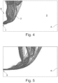
- the figure 4 shows a nozzle 1 as a swirl nozzle for blowing gas 2 into an incineration plant 3.
- the incineration plant is shown schematically as the first flue gas flue 4 figure 5 a conventional jet nozzle 5, which promotes the same volume flow of gas in the flue 4. Comparing the figures clearly shows that the injected gas is 2 in figure 4 remains on the front wall 6 of the flue 4 and does not penetrate as far into the flue 4 as in the figure 5 , in which the gas 2 reaches the middle of the flue gas train 4 much further and is only distributed there in a fan shape.
- the reference numerals 7 and 8 show large jet nozzles on the rear wall 9 of the flue gas flue 4.
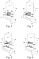
- On the front wall 6 are in the Figures 6 and 7 each above large jet nozzles 10 and including a rear large jet nozzle (not shown) arranged to promote the gas 2 in the flue gas flue 4.
- Smaller nozzles are arranged horizontally next to the lower, covered, large jet nozzles, which are used in the in figure 6 shown example as a small jet nozzle 11 and in figure 7 are designed as a small swirl nozzle 12.
- a small nozzle 11, 12 differs from a large nozzle 8, 9, 10 in that a small nozzle 11, 12 conveys a lower volume flow of gas into the flue gas flue 4.
- the figure 10 12 now shows an outer tube 23, a twist insert 26 with the cylindrical tube 20 and the twist generator 21.
- the twist generator 21 is located inside a tube 20 which is welded to the inside 22 of the outer tube 23.
- the swirl insert 26 consists of the tube 20, on the inside of which swirl vanes 24 are fastened as swirl generators 21. In the center of the blades is a central free passage 25, since the ends of the blades do not touch there.
- the nozzle 30 shown has a nozzle tube 31 with tangential inlet channels 32, 33, 34 distributed around the circumference.
- the inlet channels are distributed evenly around the circumference in a conical area 35 of the nozzle tube 31 and allow gas to be fed in there in addition to the gas guided in the nozzle tube 31 in order to generate a swirl in the nozzle 30 .
- the inlet channels 32 , 33 , 34 thus serve as swirl generators attached to the inside of the nozzle tube 31 .
- the figure 12 a nozzle pipe 41 with a spiral gas guide 42 attached to the inner circumference.
Description
Die Erfindung betrifft eine Düse zum Einblasen von Gas in eine Verbrennungsanlage mit einem Rohr und einem Drallerzeuger, einen Rauchgaszug mit einer derartigen Düse und ein Verfahren zur Verwendung einer derartigen Düse.The invention relates to a nozzle for blowing gas into a combustion system with a pipe and a swirl generator, a flue gas flue with such a nozzle and a method for using such a nozzle.
Sekundärluftdüsen in Müllverbrennungsanlagen werden nach aktuellem Stand der Technik als Strahldüsen ausgeführt. Hierbei sind Druck und Düsendurchmesser die primären Auslegungsparameter. Der Druck beeinflusst primär die Eintrittsgeschwindigkeit, der Durchmesser den Volumenstrom. Der Gesamt-Volumenstrom ergibt sich aus der Düsenanzahl. Die Düseneinsätze können als Gussbauteil gefertigt werden.According to the current state of the art, secondary air nozzles in waste incineration plants are designed as jet nozzles. Here, pressure and nozzle diameter are the primary design parameters. The pressure primarily influences the inlet velocity, the diameter the volume flow. The total volume flow results from the number of nozzles. The nozzle inserts can be manufactured as a cast component.
In Müllverbrennungsanlagen tritt an der Vorderwand häufig ein schlecht durchmischter Bereich mit Luftmangel auf, was zu erhöhten CO-Konzentrationen und CO-Peaks führen kann, insbesondere bei einem hohen Heizwert des Brennstoffs, wie dies beispielsweise auch bei der Verwendung von kochkalorischen Brennstoffen und Müllverbrennungsanlagen mit Rostfeuerung auftreten kann.In incinerators, there is often a poorly mixed area of air starvation at the front wall, which can lead to increased CO concentrations and CO peaks, particularly where the fuel has a high calorific value, such as when using cooking caloric fuels and grate-fired incinerators can occur.
Die
Beim Einsatz dieser Düsen kann Rauchgas zum im Düsenkonus angeordneten Regelkörper gelangen und Ablagerungen am Drallkörper können dessen Beweglichkeit beeinträchtigen.When using these nozzles, flue gas can get to the control body arranged in the nozzle cone and deposits on the swirl body can impair its mobility.
Die
Die Düse ist aufwändig in ihrem Einsatz, da zwei geregelte Gaszuführungen vorgesehen werden müssen.The nozzle is complex to use, since two regulated gas feeds have to be provided.
Die
Eine Düse zum Einblasen von Gas in eine Verbrennungsanlage mit einem zylindrischen Rohr und einem im Rohr oder an der Innenseite des Rohres befestigten Drallerzeuger ist aus der
Im Einsatz ist hier mit Verschmutzungen an den Rohren und insbesondere auch am Drallkörper zu rechnen, die den Gasdurchfluss behindern.In use, contamination on the pipes and especially on the swirl body is to be expected, which will impede the gas flow.
Der Erfindung liegt daher die Aufgabe zu Grunde, eine Düse für Verbrennungsanlagen so weiterzuentwickeln, dass sie im rauen Einsatz eine lange Standzeit hat und bei gleichem Volumenstrom und Druck zu einer stärkeren Strahlaufweitung führt. Außerdem wird ein Verfahren für den Einsatz derartiger Düsen vorgestellt.The invention is therefore based on the object of further developing a nozzle for combustion systems in such a way that it has a long service life in rough use and leads to a greater jet expansion with the same volume flow and pressure. A method for using such nozzles is also presented.
Diese Aufgabe wird mit einer Düse mit den Merkmalen des Patentanspruchs 1, einem Rauchgaszug mit einer derartigen Düse nach Anspruch 15 und einem Verfahren mit den Merkmalen des Patentanspruchs 19 gelöst.This object is achieved with a nozzle having the features of
Die entwickelten Dralldüsen führen bei gleichem Volumenstrom und Druck zu einer stärkeren Strahlaufweitung und dadurch zu einer geringeren Eindringtiefe. Dies wird durch eine Impulsaufteilung in eine axiale und eine tangentiale Komponente erreicht. Bei Strahldüsen geht der Impuls vollständig in die axiale Richtung. Durch den Einsatz von Dralldüsen als Sekundärluftdüsen insbesondere in Müllverbrennungsanlagen kann ein Luftmangel in Wandnähe, insbesondere an der Vorderwand, reduziert werden.With the same volume flow and pressure, the developed swirl nozzles lead to a stronger jet expansion and thus to a lower penetration depth. This is achieved by dividing the impulse into an axial and a tangential component. With jet nozzles, the momentum is entirely in the axial direction. Through the use of swirl nozzles as secondary air nozzles, particularly in waste incineration plants, a Lack of air near the wall, especially on the front wall, can be reduced.
Der entwickelte Düseneinsatz hat eine spezielle Eindüsungscharakteristik. Wie bei an der Decke von Wohnräumen angeordneten Luftauslässen von Lüftungsanlagen wird beim Einsatz der erfindungsgemäßen Düse in einer Verbrennungsanlage ein gleichmäßiger "Luftschleier" nahe der Kesselwand erzeugt, um das Durchbrechen von CO-Strähnen zu verhindern. Mit bekannten Düseneinsätzen wurde bisher ein möglichst hoher Impuls des eingedüsten Mediums erzeugt, um eine möglichst hohe Durchmischung des Rauchgases bei möglichst niedrigem Einsatz von zugeführter Verbrennungsluft zu erreichen.The developed nozzle insert has a special injection characteristic. As with air outlets of ventilation systems arranged on the ceiling of living spaces, when the nozzle according to the invention is used in an incineration system, a uniform "air curtain" is produced near the boiler wall in order to prevent CO strands from breaking through. With known nozzle inserts, the highest possible impulse of the injected medium has hitherto been generated in order to achieve the highest possible mixing of the flue gas with the lowest possible use of supplied combustion air.
Auch wenn mit einer Düse zwei unterschiedliche Medien (bspw. rezirkuliertes Rauchgas und Luft) eingedüst werden, steht ein hoher Impuls zur effektiven Durchmischung des Rauchgas über möglichst den gesamten Kesselquerschnitt hinweg im Vordergrund.Even if two different media (e.g. recirculated flue gas and air) are injected with one nozzle, a high impulse for effective mixing of the flue gas over the entire cross-section of the boiler is important.
Die bekannten Verfahren haben jedoch immer den Nachteil, dass bedingt durch den Abstand der einzelnen Düsen und die in der Nähe der Wand noch wenig aufgefächerten Luftstrahlen Zonen gebildet werden, die keine Durchmischung erfahren. Hier kann COhaltiges Abgas die Sekundärverbrennungsebene ungehindert passieren.However, the known methods always have the disadvantage that, due to the distance between the individual nozzles and the air jets that are not very fanned out near the wall, zones are formed that are not thoroughly mixed. Here, exhaust gas containing CO can pass through the secondary combustion level unhindered.
Ziel der Auslegung ist es, einen Dralleinsatz zu konstruieren, der bei möglichst starker Drallerzeugung eine ähnliche Druck-Volumenstrom-Kennlinie aufweist wie eine konventionelle Strahldüse. Dies wird durch ein über seine gesamte Länge zylindrisches Rohr erreicht. Der Einlass ist vorzugsweise nicht abgerundet. Bei einem zu hohen Druckverlust müsste man den Düsendurchmesser sehr stark vergrößern, um ausreichende Volumenströme im konventionellen Druckbereich zu erreichen. Höhere Drücke wären nur mit einem zusätzlichen Lüfter/Kompressor erreichbar. Auch die Bauteilkosten für den größeren Drallerzeuger wären höher. Dies soll aus Kostengründen vermieden werden.The aim of the design is to construct a twist insert that has a similar pressure-volume flow characteristic as a conventional jet nozzle while generating the strongest possible twist. This is achieved by using a tube that is cylindrical over its entire length. The inlet is preferably not rounded. If the pressure loss is too high, the nozzle diameter would have to be greatly increased in order to achieve sufficient volume flows in the conventional pressure range. Higher pressures would only be achievable with an additional fan/compressor. The component costs for the larger swirl generator would also be higher. This should be avoided for cost reasons.
Ein zusätzliches Ziel der Auslegung ist es, eine möglichst gleichförmige Drallströmung am Düsenauslass zu erzeugen, möglichst ohne Rückströmungen in das Düsenrohr hinein, um einen potentiellen Eintrag von Aschepartikeln und von heißen Rauchgasen zu verhindern. Dadurch sollen Verschmutzung und Korrosion des Drallerzeugers vermieden werden. Hierbei sind gerade Schaufeln verdrillten Schaufeln, und Schaufeln mit gerader Einlaufstrecke Schaufeln ohne gerader Einlaufstrecke vorzuziehen.An additional goal of the design is to generate a swirl flow that is as uniform as possible at the nozzle outlet, if possible without backflow into the nozzle pipe, in order to prevent the potential entry of ash particles and hot flue gases. This is to prevent contamination and corrosion of the swirl generator. Straight blades are preferable to twisted blades, and blades with a straight inlet section are preferable to blades without a straight inlet section.
Viele Faktoren wirken sich unterschiedlich auf die Effektivität der Düsen aus. Ein Diffusor oder auch ein Radius am Düsenauslass reduzieren den Druckverlust, allerdings ist nur in Kombination mit einem kleinen Drallerzeuger eine anliegende Strömung zu erwarten. Zusätzlich wird die Ausbildung von Rückströmungsbereichen verstärkt, was die Gefahr der Verschmutzung und Korrosion des Düseninneren erhöht.Many factors have different effects on the effectiveness of the nozzles. A diffuser or a radius at the nozzle outlet reduce the pressure loss, but an attached flow can only be expected in combination with a small swirl generator. In addition, the formation of backflow areas is increased, which increases the risk of contamination and corrosion of the nozzle interior.
Ein Loch in der Mitte des Drallerzeugers reduziert die Ausbildung von Rückströmungsbereichen und reduziert auch den Druckverlust. Eine Verbindung der Schaufeln in der Mitte (z.B. als Stift oder Ring) ist eher von Nachteil, da hierdurch die Ausbildung von Rückströmungsbereichen verstärkt wird und sich auch der Druckverlust erhöht. Vorteilhaft sind dabei eine steifere Konstruktion und eine Fertigung des Drallerzeugers ohne äußeren, verbindenden Ring.A hole in the center of the swirler reduces the formation of backflow areas and also reduces the pressure drop. A connection of the blades in the middle (e.g. as a pin or ring) is more of a disadvantage, as this intensifies the formation of backflow areas and also increases the pressure loss. A more rigid construction and manufacture of the swirl generator without an outer, connecting ring are advantageous here.
Eine gerade Einlaufstrecke der Schaufeln reduziert den Druckverlust und ist daher von Vorteil. Der Übergang zum Drall erzeugenden Teil der Schaufeln kann verschieden ausgeführt werden, z.B. als Radius oder gekrümmtes Profil. Der Drall erzeugende Teil der Schaufeln kann ebenfalls gekrümmt sein. Die Schaufeln können weiterhin auch mit zunehmender Schaufelhöhe vom Einlauf bis zum Düsenaustritt ausgeführt werden.A straight inlet section of the blades reduces the pressure loss and is therefore an advantage. The transition to the swirl-generating part of the blades can be designed in different ways, e.g. as a radius or a curved profile. The swirl generating part of the blades can also be curved. The blades can also be designed with increasing blade height from the inlet to the nozzle outlet.
Der Drallerzeuger sollte etwas nach innen versetzt werden, um die Verschmutzung- und Korrosionsgefahr zu reduzieren. Allerdings wird hierdurch auch die Drallwirkung reduziert. Falls sich im Anlagenbetrieb ein zu starker Verschleiß zeigt, kann der Drallerzeuger weiter ins Rohrinnere versetzt werden, was durch einen höheren Drallwinkel ausgeglichen werden kann. Dieser führt zwar zu einem höheren Druckverlust, der jedoch durch einen größeren Düsendurchmesser oder einen Diffusor ausgeglichen werden kann.The swirl generator should be moved slightly inwards to reduce the risk of contamination and corrosion. However, this also reduces the swirl effect. If there is excessive wear during system operation, the swirl generator can be moved further inside the pipe, which can be compensated for by a higher swirl angle. Although this leads to a higher pressure loss, this can be compensated for by a larger nozzle diameter or a diffuser.
Der Drallerzeuger kann auch in einem konisch zusammenlaufenden Teil eines konventionellen Strahldüseneinsatzes eingesetzt sein. Auch eine Drallerzeugung durch tangentiale Einbringung der Luft in die Düse mit mehreren über den Umfang verteilten Eintrittskanälen ist vorteilhaft. Hierfür sind aber eine aufwendigere Konstruktion und eine komplexe Auslegung notwendig.The twist generator can also be used in a conically converging part of a conventional jet nozzle insert. It is also advantageous to generate a swirl by introducing the air tangentially into the nozzle with a plurality of inlet channels distributed over the circumference. However, this requires a more expensive construction and a complex design.
Herstellungstechnisch ist es vorteilhaft, wenn das Rohr in einem Außenrohr angeordnet ist. Der Dralleinsatz besteht somit aus einem Rohr, in dem der Drallerzeuger angeordnet ist. Dieses Rohr ist in das Außenrohr eingeschweißt. Dadurch entsteht ein Düseneinsatz, der in ein Düsenrohr eingesetzt werden kann. Das Rohr hat vorzugsweise eine Wanddicke von 2 bis 5 mm. Der Innendurchmesser des Rohrs beträgt vorzugsweise 40 bis 80 mm und liegt im Ausführungsbeispiel bei etwa 50 mm.In terms of manufacturing technology, it is advantageous if the tube is arranged in an outer tube. The twist insert thus consists of a tube in which the twist generator is arranged. This tube is welded into the outer tube. This creates a Nozzle insert that can be inserted into a nozzle tube. The tube preferably has a wall thickness of 2 to 5 mm. The inner diameter of the tube is preferably 40 to 80 mm and is approximately 50 mm in the exemplary embodiment.
Es hat sich als vorteilhaft erwiesen, wenn der Drallerzeuger Schaufelprofile hat, die zur Erzeugung des Dralls einen Winkel von 15° bis 60° und vorzugsweise von 40° bis 50° aufweisen. Ein Ausführungsbeispiel hat einen Winkel von 45°. Bei größeren Winkeln erhöht sich die Drallwirkung. Dies führt aber zu einem höheren Druckverlust und der Ausbildung von Rückströmungsbereichen.It has proven to be advantageous if the swirl generator has blade profiles which have an angle of 15° to 60° and preferably of 40° to 50° to generate the swirl. An exemplary embodiment has an angle of 45°. At larger angles, the twisting effect increases. However, this leads to a higher pressure loss and the formation of backflow areas.
Um die Düse zu schützen wird vorgeschlagen, dass der Abstand des Drallerzeugers vom Rohrauslass und somit vom Kesseleintritt etwa 10 bis 30 mm beträgt. Der Drallerzeuger sollte daher im Rohr um mindestens 5 mm und vorzugsweise etwa 10 mm nach innen versetzt angeordnet sein.In order to protect the nozzle, it is suggested that the distance between the swirl generator and the pipe outlet and thus from the boiler inlet is about 10 to 30 mm. The twist generator should therefore be offset inward in the pipe by at least 5 mm and preferably about 10 mm.
Der Drallerzeuger hat vorzugsweise mehr als 4 und beispielsweise 6 über den Umfang verteilte Drallschaufeln. In der Regel liegt die Anzahl der Schaufeln bei 4 bis 8 Stück.The swirl generator preferably has more than 4 and, for example, 6 swirl vanes distributed over the circumference. As a rule, the number of blades is 4 to 8 pieces.
Die Schaufeln des Drallerzeugers sollten eine durchschnittliche Dicke des Schaufelprofils zwischen 1 und 6 mm und vorzugsweise zwischen 2 und 4 aufweisen. Ihre Länge in axialer Richtung des Düsenrohrs liegt bei 20 bis 60 mm und vorzugsweise bei etwa 30 mm, wovon 30 bis 70 % und vorzugsweise etwa 50 % als gerade Einlaufstrecke ausgebildet sind, um den Druckverlust zu reduzieren.The vanes of the swirler should have an average airfoil thickness between 1 and 6 mm and preferably between 2 and 4 mm. Its length in the axial direction of the nozzle tube is 20 to 60 mm and preferably about 30 mm, of which 30 to 70% and preferably about 50% is designed as a straight inlet section in order to reduce the pressure loss.
Eine Verschmutzung der Schaufeln wird reduziert, wenn der Drallerzeuger Drallschaufeln aufweist, die einen zentralen freien Durchlass bilden, dessen Durchmesser größer ist als 20 % des Innendurchmessers des Rohrs. Dabei ist es vorteilhaft, wenn sich die Schaufeln nicht berühren. In der Praxis sollte der Durchmesser des freien Lochs in der Mitte der Schaufeln bei 10 bis 30 mm, wie beispielsweise bei 16 mm liegen. Das sind dann etwa 30 % des Rohrinnendurchmessers.Fouling of the vanes is reduced if the swirler has swirl vanes forming a central free passage with a diameter greater than 20% of the inside diameter of the tube. It is advantageous if the blades do not touch. In practice, the diameter of the clear hole in the center of the blades should be 10 to 30 mm, such as 16 mm. That is then about 30% of the inner diameter of the pipe.
Als zusätzliche Option wird eine variable Einstellung des Dralls vorgeschlagen. Dies kann entweder mittels eines mechanisch verstellbaren Anstellwinkels des Drallerzeugers oder mittels zweier konzentrischer Kanäle mit unterschiedlichem Drallwinkel (z.B. drallfreier Kernstrahl und verdrallter Ringspalt) erreicht werden. Die Kanäle können dabei mit einem variablen Volumenstromverhältnis durchströmt werden. So können beispielsweise zwei Sammler jeweils mit einer Druckregelung über ein Stellventil vorgesehen sein. Eine solche Ausführung ist primär für eine flexible Fahrweise von Vorteil und zum Beispiel bei Verschiebungen der Verbrennungszone durch Variation des mittleren Müllheizwertes oder bei Variation der Last sinnvoll. Auch das Einbringen und Mischen von verschiedenen Gasen (z.B. Luft mit Rezirkulations-Gas oder Luft mit Dampf) sind hiermit möglich.A variable setting of the twist is suggested as an additional option. This can be achieved either by means of a mechanically adjustable angle of attack of the swirl generator or by means of two concentric channels with different swirl angles (eg swirl-free core jet and swirled annular gap). The channels can use one variable volume flow ratio. For example, two collectors can each be provided with a pressure control via a control valve. Such a design is primarily advantageous for a flexible mode of operation and makes sense, for example, when the combustion zone is shifted by varying the average calorific value of the waste or when varying the load. It is also possible to introduce and mix different gases (e.g. air with recirculation gas or air with steam).
Eine besondere Ausführungsform sieht daher vor, dass der Drallerzeuger bewegliche Drallschaufeln aufweist.A special embodiment therefore provides that the swirl generator has movable swirl vanes.
Eine alternative Ausführungsform sieht vor, dass das Rohr mindestens einen und vorzugsweise mehrere am Umfang verteilte tangentiale Eintrittskanäle aufweist. Alternativ oder kumulativ kann die Düse auch ein Rohr mit mindestens einem und vorzugsweise mehreren am Umfang verteilten spiralförmigen Gasführungen aufweisen.An alternative embodiment provides that the tube has at least one and preferably several tangential inlet channels distributed around the circumference. Alternatively or cumulatively, the nozzle can also have a tube with at least one and preferably a plurality of spiral-shaped gas ducts distributed around the circumference.
Vorteilhaft ist es, wenn die Machzahl Ma der Düse unter 0,4 liegt.It is advantageous if the Mach number Ma of the nozzle is below 0.4.
Wenn die Düse in einer Feuerung eingebaut ist, dann sollte sie in einer Wand eines Rauchgaszuges, vorzugsweise an der Vorderwand eines Rauchgaszuges, angeordnet sein. Vorteilhaft ist es, wenn zwei der Düsen nebeneinander angeordnet sind und einen gegensinnigen Drall ausüben.If the nozzle is installed in a furnace, then it should be located in a wall of a flue, preferably at the front wall of a flue. It is advantageous if two of the nozzles are arranged next to one another and exert a twist in opposite directions.
Außerdem kann eine Düse zum Einblasen von Gas ohne Drall, die auch als Strahldüse bezeichnet wird, neben einer Düse zum Einblasen von Gas mit Drall, die auch als Dralldüse bezeichnet wird, angeordnet sein.Also, a non-swirl gas injection nozzle, also called a jet nozzle, may be arranged next to a swirl gas injection nozzle, also called a swirl nozzle.
Ein Verfahren zur Verwendung einer derartigen Düse dient dem Einblasen eines Gases, wie insbesondere von Luft- oder Sauerstoff zur Sauerstoffanreicherung beispielsweise an einer Wand und insbesondere der Vorderwand einer Verbrennungsanlage wie beispielsweise einer Müllverbrennungsanlage, vorzugsweise bereits im ersten Zug. Dieses Verfahren eignet sich insbesondere bei einem hohen Heizwert (z.B. Ersatzbrennstoff) und bei einer Rostfeuerung.A method for using such a nozzle serves to blow in a gas, such as in particular air or oxygen for oxygen enrichment, for example on a wall and in particular the front wall of an incinerator such as a waste incineration plant, preferably already in the first pass. This method is particularly suitable for a high calorific value (e.g. substitute fuel) and for grate firing.
Die Düsen können zur Erweiterung bestehender Verbrennungsluftsysteme im Bereich der Sekundärverbrennung eingesetzt werden. Dabei können die Dralldüsen einzelne Düsen ersetzen oder zusätzlich eingesetzt werden. Vorteilhaft ist dabei eine gegensinnige Drehrichtung benachbarter Düsen.The nozzles can be used to expand existing combustion air systems in the area of secondary combustion. The swirl nozzles can replace individual nozzles or be used in addition. An opposite direction is advantageous Direction of rotation of adjacent nozzles.
Bei diesem Verfahren ist es vorteilhaft, wenn der Gasvolumenstrom, der durch die Düse geleitet wird, auf 100 bis 1500 Nm3/h pro Düse eingestellt wird. Dabei ergibt sich ein Betriebsdruck im Sammler der Düsenebene von ca. 5 bis 100 mbar und die Eintrittsgeschwindigkeit liegt bei 10 bis 100 m/s. Bei einem Ausführungsbeispiel liegt der Luftvolumenstrom bei 100 bis 500 Nm3/h bei einem Betriebsdruck im Sammler von 10 bis 60 mbar und einer Eintrittsgeschwindigkeit von 20 bis 80 m/s.In this method, it is advantageous if the gas volume flow that is passed through the nozzle is set to 100 to 1500 Nm 3 /h per nozzle. This results in an operating pressure in the collector at the nozzle level of approx. 5 to 100 mbar and the entry speed is 10 to 100 m/s. In one embodiment, the air volume flow is 100 to 500 Nm 3 /h at an operating pressure in the collector of 10 to 60 mbar and an entry speed of 20 to 80 m/s.
Die Düse kann beispielsweise auch für Luft, Rezirkulationsgas, Dampf, CO2, O2 und N2 und Mischungen daraus genutzt werden. Bei der Einbringung von Rezirkulationsgas, das meist partikelbeladen ist, oder Dampf ist allerdings mit einem höheren Verschleiß durch Verschmutzung und Korrosion zu rechnen.For example, the nozzle can also be used for air, recycle gas, steam, CO 2 , O 2 and N 2 and mixtures thereof. However, when recirculation gas, which is mostly particle-laden, or steam is introduced, higher wear due to contamination and corrosion is to be expected.
Derartige Düsen können als Dralleinsatz mittels 3D-Druck aus Edelstahl (z.B. 17-4PH bzw. 1.4548) gefertigt werden und alternativ auch beispielsweise mittels Feinguss oder CNC-Fräsen.Such nozzles can be manufactured as a twist insert using 3D printing from stainless steel (e.g. 17-4PH or 1.4548) and alternatively also, for example, using investment casting or CNC milling.
Ein Dralleinsatz ist in ein Außenrohr einschweißbar. Der Dralleinsatz ist jedoch auch als Schweißkonstruktion beispielsweise mit in ein Rohr eingeschweißten Blechen ausführbar - alternativ zu 3D-Druck, Feinguss oder CNC-Fräsen.A twist insert can be welded into an outer tube. However, the twist insert can also be implemented as a welded construction, for example with sheet metal welded into a tube - as an alternative to 3D printing, investment casting or CNC milling.
Eine weitere Verringerung der Verschmutzungs- und Korrosionsgefahr ist z.B. durch abgerundete Schaufeln oder durch eine mittige Nase oder Spitze möglich.A further reduction in the risk of contamination and corrosion is possible, for example, with rounded blades or with a central nose or point.
Je nach Ausführungsform kann die Dralldüse auch eine geringere Sogwirkung im Vergleich zu Strahldüsen haben, was zu einem geringeren Partikeleintrag an der entsprechenden Kesselwand führt.Depending on the embodiment, the swirl nozzle can also have a lower suction effect compared to jet nozzles, which leads to fewer particles entering the corresponding boiler wall.
Ausführungsbeispiele der Erfindung sind in der Zeichnung dargestellt und werden im Folgenden näher erläutert. Es zeigt die
Figur 1- ein Rohr mit einem Drallerzeuger
Figur 2- einen Blick in einen Drallerzeuger
- Figur 3
- einen Dralleinsatz in einem Außenrohr, die als Düseneinsatz in einem Düsenrohr angeordnet sind,
Figur 4- eine Gasverteilung am Ausgang einer an der vorderen Kesselwand angeordneten Dralldüse,
Figur 5- eine Gasverteilung einer an derselben Stelle wie in
Figur 1 Figur 6einen Rauchgaszug mit 4 Strahldüsen und links unten mit einer Strahldüse als kleine DüseFigur 7- den in
Figur 6 Figur 8einen Rauchgaszug mit 4 Strahldüsen und links oben mit einer Strahldüse als kleine DüseFigur 9- den in
Figur 8 Figur 10- links ein Außenrohr einer Düse, mittig zwei Dralleinsätze mit Rohr und Drallerzeuger und rechts einen Düseneinsatz aus einem Außenrohr mit einem eingeschweißten Dralleinsatz,
Figur 11- eine Düse mit einer Drallerzeugung durch tangentiale Einbringung des Gases in einem konischen Bereich der Düse und
Figur 12- ein Rohr mit einer Drall erzeugenden Innenkontur als Düse oder Zuleitung zu einer Düse.
- figure 1
- a tube with a swirl generator
- figure 2
- a look into a swirl generator
- figure 3
- a swirl insert in an outer tube, which are arranged as a nozzle insert in a nozzle tube,
- figure 4
- a gas distribution at the outlet of a swirl nozzle arranged on the front boiler wall,
- figure 5
- a gas distribution a in the same place as in
figure 1 arranged and operated with the same volume flow and pressure conventional jet nozzle, - figure 6
- a flue gas flue with 4 jet nozzles and at the bottom left with a jet nozzle as a small nozzle
- figure 7
- the in
figure 6 shown flue with a twist nozzle as a small nozzle at the bottom right, - figure 8
- a flue with 4 jet nozzles and at the top left with a jet nozzle as a small nozzle
- figure 9
- the in
figure 8 shown flue with a swirl nozzle as a small nozzle at the top right, - figure 10
- on the left an outer tube of a nozzle, in the middle two swirl inserts with tube and swirl generator and on the right a nozzle insert made of an outer tube with a welded-in swirl insert,
- figure 11
- a nozzle with a swirl generation by tangential introduction of the gas in a conical area of the nozzle and
- figure 12
- a tube with an inner contour that generates a twist as a nozzle or feed line to a nozzle.
Die
In der
Die
Die
Den Vorteil der Dralldüse in der Praxis zeigen auch die
Waagerecht neben den unteren verdeckten, großen Strahldüsen sind kleinere Düsen angeordnet, die bei dem in
Während von ganz unten durch den Rost Primärverbrennungsgas 16 zugeführt wird, entsteht in
Ähnlich ist es, wenn wie in den
Die
Die in
Letztlich zeigt die
Claims (19)
- Nozzle (1) for blowing gas (2) into a combustion plant (3) with a pipe (20, 31, 41) and a swirl generator (21), wherein the pipe (20, 31, 41) is cylindrical and the swirl generator (21) is attached on the inner side (22) of the pipe (20, 31, 41), wherein the swirl generator has swirl vanes with a straight inlet section, characterized in that the swirl vanes (24) have a length of 20 to 60 mm, of which 30% to 70% and preferably approximately 50% is designed as a straight inlet section.
- Nozzle according to claim 1, characterized in that the pipe (20) is arranged in an outer pipe (23).
- Nozzle according to claim 2, characterized in that the pipe (20) is welded into the outer pipe (23).
- Nozzle according to one of claims 2 or 3, characterized in that the pipe (20) has a wall thickness of 2 to 5 mm.
- Nozzle according to one of the preceding claims, characterized in that the inner diameter of the pipe (20, 31, 41) is 40 to 80 mm and preferably approximately 50 mm.
- Nozzle according to one of the preceding claims, characterized in that the swirl generator (21) has a swirl angle of 15° to 60° and preferably from 40° to 50°.
- Nozzle according to one of the preceding claims, characterized in that the swirl generator (21) is offset inwardly in the pipe (20, 31, 41) by at least 5 mm and preferably by approximately 10 mm.
- Nozzle according to one of the preceding claims, characterized in that the swirl generator (21) has more than 4 and preferably 6 swirl vanes (24) distributed across the circumference.
- Nozzle according to one of the preceding claims, characterized in that the swirl generator (21) has swirl vanes (24) with an average thickness of the vane profile of between 1 and 6 mm and preferably between 2 and 4 mm.
- Nozzle according to one of the preceding claims, characterized in that the swirl vanes (24) form a central free passage (25) whose diameter is greater than 20% of the free inner diameter of the pipe (20, 31, 41).
- Nozzle according to one of the preceding claims, characterized in that the swirl generator (21) has movable swirl vanes (24).
- Nozzle according to one of the preceding claims, characterized in that the pipe (20, 31, 41) has at least one and preferably multiple tangential inlet channels (32, 33, 34) distributed on the circumference.
- Nozzle according to one of the preceding claims, characterized in that the pipe (20, 31, 41) has at least one and preferably multiple spiral-shaped gas ducts (42) distributed on the circumference.
- Nozzle according to one of the preceding claims, characterized in that the Mach number Ma of the nozzle is less than 0.4.
- Flue gas pipe with a nozzle (1) according to one of the preceding claims, characterized in that the nozzle is arranged in a wall of the flue gas pipe (4).
- Flue gas pipe according to claim 15, characterized in that the nozzle (1) is arranged on the front wall (6) of the flue gas pipe (4).
- Flue gas pipe according to claim 15 or 16, characterized in that two of the nozzles (1) are arranged adjacent to one another and exert a swirl in opposite directions.
- Flue gas pipe according to one of claims 15 to 17, characterized in that a nozzle for blowing in gas (2) without a swirl, which is designated as a jet nozzle, is arranged next to a nozzle for blowing in gas (2) with a swirl according to one of claims 1 to 14, which is also designated as a swirl nozzle.
- Method for using a nozzle according to one of preceding claims 1 to 14, characterized in that a volume flow made from air and/or flue gas, which is guided through the nozzle (1), is set to 100 to 1500 Nm3/h.
Applications Claiming Priority (1)
| Application Number | Priority Date | Filing Date | Title |
|---|---|---|---|
| DE102021002508.3A DE102021002508A1 (en) | 2021-05-12 | 2021-05-12 | Nozzle for injecting gas into an incinerator with a tube and a swirler, flue with such a nozzle and method for using such a nozzle |
Publications (3)
| Publication Number | Publication Date |
|---|---|
| EP4089325A1 EP4089325A1 (en) | 2022-11-16 |
| EP4089325C0 EP4089325C0 (en) | 2023-08-09 |
| EP4089325B1 true EP4089325B1 (en) | 2023-08-09 |
Family
ID=81392737
Family Applications (1)
| Application Number | Title | Priority Date | Filing Date |
|---|---|---|---|
| EP22170612.0A Active EP4089325B1 (en) | 2021-05-12 | 2022-04-28 | Nozzle for blowing gas into a combustion plant with a pipe and a swirl generator, flue with such a nozzle and method of using such a nozzle |
Country Status (5)
| Country | Link |
|---|---|
| US (1) | US20220364725A1 (en) |
| EP (1) | EP4089325B1 (en) |
| JP (1) | JP2022176137A (en) |
| CN (1) | CN115338050A (en) |
| DE (1) | DE102021002508A1 (en) |
Families Citing this family (1)
| Publication number | Priority date | Publication date | Assignee | Title |
|---|---|---|---|---|
| DK3739264T3 (en) * | 2019-05-13 | 2021-08-30 | Doosan Lentjes Gmbh | Solid material incineration plant and method of replacing its nozzle insert |
Citations (2)
| Publication number | Priority date | Publication date | Assignee | Title |
|---|---|---|---|---|
| US20100205971A1 (en) * | 2009-02-18 | 2010-08-19 | Delavan Inc | Fuel nozzle having aerodynamically shaped helical turning vanes |
| CN105737203A (en) * | 2016-03-16 | 2016-07-06 | 中国科学院工程热物理研究所 | Swirler and pre-mixing combustor adopting same |
Family Cites Families (19)
| Publication number | Priority date | Publication date | Assignee | Title |
|---|---|---|---|---|
| DE4301082C2 (en) | 1993-01-16 | 1997-11-27 | Steinmueller Gmbh L & C | Method for supplying an O¶2¶-containing combustion gas for the combustion of lumpy combustible material in a combustion chamber with the associated grate of an incinerator and device for carrying out the method |
| DE19613777C2 (en) | 1996-04-04 | 2002-01-17 | Michael Mimor | Incinerator and post-combustion process |
| US5727480A (en) | 1996-04-17 | 1998-03-17 | Foster Wheeler International, Inc. | Over-fire air control system for a pulverized solid fuel furnace |
| DE19735345C2 (en) | 1997-08-14 | 2000-05-25 | Viessmann Werke Kg | Oil or gas fan burners |
| MXPA06008994A (en) * | 2004-02-12 | 2006-12-14 | Alstom Tehcnology Ltd | Premixing burner arrangement for operating a burner chamber and method for operating a burner chamber. |
| CN1814355A (en) * | 2005-02-01 | 2006-08-09 | 财团法人工业技术研究院 | Gasifying furnace nozzle |
| DE102007030269B4 (en) * | 2007-06-28 | 2014-07-17 | Mitsubishi Hitachi Power Systems Europe Gmbh | Pulverized coal burner for burning fuel supplied in dense phase conveying |
| US20100058767A1 (en) * | 2008-09-05 | 2010-03-11 | General Electric Company | Swirl angle of secondary fuel nozzle for turbomachine combustor |
| EP2397764A1 (en) | 2010-06-18 | 2011-12-21 | Siemens Aktiengesellschaft | Turbine burner |
| CN101915150A (en) * | 2010-09-20 | 2010-12-15 | 中国人民解放军军事交通学院 | Exhaust pipe for enhancing mobility of tail gas rotational flow and eliminating urea solution jet crystallization |
| JP5530373B2 (en) | 2011-01-12 | 2014-06-25 | バブコック日立株式会社 | Boiler equipment |
| CN103148501B (en) * | 2013-03-14 | 2015-05-13 | 福建绿源新能源科技有限公司 | Secondary air structure for boiler burning biomass formed fuel |
| EP3058276B1 (en) | 2013-10-17 | 2020-01-15 | Hatch Pty Ltd | A solid fuel burner with dispersion apparatus |
| GB2551166A (en) * | 2016-06-08 | 2017-12-13 | Doosan Babcock Ltd | Burner |
| KR101736838B1 (en) | 2017-04-20 | 2017-05-29 | 채재우 | Hybrid type combustion device using pyrolysis of water and combustion air |
| CN107143881B (en) * | 2017-05-16 | 2020-02-14 | 西北工业大学 | Multi-point direct injection head structure for low-pollution combustion chamber of gas turbine |
| ES2854275T3 (en) | 2018-12-07 | 2021-09-21 | Doosan Lentjes Gmbh | Incineration plant with nozzle and reactor for cleaning gaseous effluents with nozzle |
| DK3739264T3 (en) * | 2019-05-13 | 2021-08-30 | Doosan Lentjes Gmbh | Solid material incineration plant and method of replacing its nozzle insert |
| CN110848693B (en) * | 2019-10-08 | 2020-11-10 | 西安交通大学 | Dual-purpose combustor of coal, gas with abrasionproof distortion blade flow equalizes |
-
2021
- 2021-05-12 DE DE102021002508.3A patent/DE102021002508A1/en active Pending
-
2022
- 2022-04-28 EP EP22170612.0A patent/EP4089325B1/en active Active
- 2022-05-04 US US17/736,599 patent/US20220364725A1/en active Pending
- 2022-05-11 JP JP2022077892A patent/JP2022176137A/en active Pending
- 2022-05-12 CN CN202210517951.0A patent/CN115338050A/en active Pending
Patent Citations (2)
| Publication number | Priority date | Publication date | Assignee | Title |
|---|---|---|---|---|
| US20100205971A1 (en) * | 2009-02-18 | 2010-08-19 | Delavan Inc | Fuel nozzle having aerodynamically shaped helical turning vanes |
| CN105737203A (en) * | 2016-03-16 | 2016-07-06 | 中国科学院工程热物理研究所 | Swirler and pre-mixing combustor adopting same |
Also Published As
| Publication number | Publication date |
|---|---|
| EP4089325C0 (en) | 2023-08-09 |
| DE102021002508A1 (en) | 2022-11-17 |
| CN115338050A (en) | 2022-11-15 |
| US20220364725A1 (en) | 2022-11-17 |
| JP2022176137A (en) | 2022-11-25 |
| EP4089325A1 (en) | 2022-11-16 |
Similar Documents
| Publication | Publication Date | Title |
|---|---|---|
| EP2588805B1 (en) | Burner | |
| DE2936073C2 (en) | Combustion process to reduce the emission of nitrogen oxides and smoke | |
| EP0675322B1 (en) | Premix burner | |
| EP1802915B1 (en) | Gas turbine burner | |
| EP0781967B1 (en) | Annular combustion chamber for gas turbine | |
| EP0794383B1 (en) | Method of operating a pressurised atomising nozzle | |
| EP0433790B1 (en) | Burner | |
| EP0834040B1 (en) | Combustion chamber with a burner arrangement and method of operating a combustion chamber | |
| DE102014102780A1 (en) | System and method for air flow conditioning at a rape level | |
| EP3087323B1 (en) | Fuel nozzle, burner having such a fuel nozzle, and gas turbine having such a burner | |
| EP0684428A2 (en) | Device for injecting air into the combustion space of a flare burner and flare burner | |
| DE102005015152A1 (en) | Premix burner for a gas turbine combustor | |
| EP0918191A1 (en) | Burner for the operation of a heat generator | |
| EP0775869B1 (en) | Premix burner | |
| EP4089325B1 (en) | Nozzle for blowing gas into a combustion plant with a pipe and a swirl generator, flue with such a nozzle and method of using such a nozzle | |
| EP1730442B1 (en) | Gas injector | |
| DE19537636B4 (en) | Power plant | |
| CH678100A5 (en) | ||
| EP2558781B1 (en) | Swirl generator for a torch | |
| DE19507088B4 (en) | premix | |
| DE19704802A1 (en) | Device and method for burning fuel | |
| EP3450846B1 (en) | Combustion plant and method for operating the same | |
| DE19917662A1 (en) | Burner for liquid and/or gas fuel, with at least two air or hydrogen supply jets before burner jet in outflow direction | |
| WO2023030610A1 (en) | Gas-fired burner, in particular for a drying drum of an asphalt mixing plant | |
| WO2011022847A1 (en) | Burner for generating a hot gas stream |
Legal Events
| Date | Code | Title | Description |
|---|---|---|---|
| PUAI | Public reference made under article 153(3) epc to a published international application that has entered the european phase |
Free format text: ORIGINAL CODE: 0009012 |
|
| STAA | Information on the status of an ep patent application or granted ep patent |
Free format text: STATUS: THE APPLICATION HAS BEEN PUBLISHED |
|
| STAA | Information on the status of an ep patent application or granted ep patent |
Free format text: STATUS: REQUEST FOR EXAMINATION WAS MADE |
|
| AK | Designated contracting states |
Kind code of ref document: A1 Designated state(s): AL AT BE BG CH CY CZ DE DK EE ES FI FR GB GR HR HU IE IS IT LI LT LU LV MC MK MT NL NO PL PT RO RS SE SI SK SM TR |
|
| 17P | Request for examination filed |
Effective date: 20221103 |
|
| RBV | Designated contracting states (corrected) |
Designated state(s): AL AT BE BG CH CY CZ DE DK EE ES FI FR GB GR HR HU IE IS IT LI LT LU LV MC MK MT NL NO PL PT RO RS SE SI SK SM TR |
|
| GRAP | Despatch of communication of intention to grant a patent |
Free format text: ORIGINAL CODE: EPIDOSNIGR1 |
|
| STAA | Information on the status of an ep patent application or granted ep patent |
Free format text: STATUS: GRANT OF PATENT IS INTENDED |
|
| INTG | Intention to grant announced |
Effective date: 20230413 |
|
| GRAS | Grant fee paid |
Free format text: ORIGINAL CODE: EPIDOSNIGR3 |
|
| GRAA | (expected) grant |
Free format text: ORIGINAL CODE: 0009210 |
|
| STAA | Information on the status of an ep patent application or granted ep patent |
Free format text: STATUS: THE PATENT HAS BEEN GRANTED |
|
| AK | Designated contracting states |
Kind code of ref document: B1 Designated state(s): AL AT BE BG CH CY CZ DE DK EE ES FI FR GB GR HR HU IE IS IT LI LT LU LV MC MK MT NL NO PL PT RO RS SE SI SK SM TR |
|
| REG | Reference to a national code |
Ref country code: GB Ref legal event code: FG4D Free format text: NOT ENGLISH |
|
| REG | Reference to a national code |
Ref country code: CH Ref legal event code: EP |
|
| REG | Reference to a national code |
Ref country code: DE Ref legal event code: R096 Ref document number: 502022000079 Country of ref document: DE |
|
| REG | Reference to a national code |
Ref country code: IE Ref legal event code: FG4D Free format text: LANGUAGE OF EP DOCUMENT: GERMAN |
|
| U01 | Request for unitary effect filed |
Effective date: 20230816 |
|
| U07 | Unitary effect registered |
Designated state(s): AT BE BG DE DK EE FI FR IT LT LU LV MT NL PT SE SI Effective date: 20230824 |
|
| PG25 | Lapsed in a contracting state [announced via postgrant information from national office to epo] |
Ref country code: GR Free format text: LAPSE BECAUSE OF FAILURE TO SUBMIT A TRANSLATION OF THE DESCRIPTION OR TO PAY THE FEE WITHIN THE PRESCRIBED TIME-LIMIT Effective date: 20231110 |
|
| PG25 | Lapsed in a contracting state [announced via postgrant information from national office to epo] |
Ref country code: IS Free format text: LAPSE BECAUSE OF FAILURE TO SUBMIT A TRANSLATION OF THE DESCRIPTION OR TO PAY THE FEE WITHIN THE PRESCRIBED TIME-LIMIT Effective date: 20231209 |
|
| PG25 | Lapsed in a contracting state [announced via postgrant information from national office to epo] |
Ref country code: RS Free format text: LAPSE BECAUSE OF FAILURE TO SUBMIT A TRANSLATION OF THE DESCRIPTION OR TO PAY THE FEE WITHIN THE PRESCRIBED TIME-LIMIT Effective date: 20230809 Ref country code: NO Free format text: LAPSE BECAUSE OF FAILURE TO SUBMIT A TRANSLATION OF THE DESCRIPTION OR TO PAY THE FEE WITHIN THE PRESCRIBED TIME-LIMIT Effective date: 20231109 Ref country code: IS Free format text: LAPSE BECAUSE OF FAILURE TO SUBMIT A TRANSLATION OF THE DESCRIPTION OR TO PAY THE FEE WITHIN THE PRESCRIBED TIME-LIMIT Effective date: 20231209 Ref country code: HR Free format text: LAPSE BECAUSE OF FAILURE TO SUBMIT A TRANSLATION OF THE DESCRIPTION OR TO PAY THE FEE WITHIN THE PRESCRIBED TIME-LIMIT Effective date: 20230809 Ref country code: GR Free format text: LAPSE BECAUSE OF FAILURE TO SUBMIT A TRANSLATION OF THE DESCRIPTION OR TO PAY THE FEE WITHIN THE PRESCRIBED TIME-LIMIT Effective date: 20231110 |
|
| PG25 | Lapsed in a contracting state [announced via postgrant information from national office to epo] |
Ref country code: PL Free format text: LAPSE BECAUSE OF FAILURE TO SUBMIT A TRANSLATION OF THE DESCRIPTION OR TO PAY THE FEE WITHIN THE PRESCRIBED TIME-LIMIT Effective date: 20230809 |