EP4088954B1 - Dual use trailer vehicle - Google Patents
Dual use trailer vehicle Download PDFInfo
- Publication number
- EP4088954B1 EP4088954B1 EP22172475.0A EP22172475A EP4088954B1 EP 4088954 B1 EP4088954 B1 EP 4088954B1 EP 22172475 A EP22172475 A EP 22172475A EP 4088954 B1 EP4088954 B1 EP 4088954B1
- Authority
- EP
- European Patent Office
- Prior art keywords
- vehicle
- slave
- master
- coupling
- slave vehicle
- Prior art date
- Legal status (The legal status is an assumption and is not a legal conclusion. Google has not performed a legal analysis and makes no representation as to the accuracy of the status listed.)
- Active
Links
Images


Classifications
-
- B—PERFORMING OPERATIONS; TRANSPORTING
- B62—LAND VEHICLES FOR TRAVELLING OTHERWISE THAN ON RAILS
- B62D—MOTOR VEHICLES; TRAILERS
- B62D53/00—Tractor-trailer combinations; Road trains
- B62D53/04—Tractor-trailer combinations; Road trains comprising a vehicle carrying an essential part of the other vehicle's load by having supporting means for the front or rear part of the other vehicle
- B62D53/045—Tractor-trailer combinations; Road trains comprising a vehicle carrying an essential part of the other vehicle's load by having supporting means for the front or rear part of the other vehicle with rigid linkage in the horizontal plane
-
- B—PERFORMING OPERATIONS; TRANSPORTING
- B62—LAND VEHICLES FOR TRAVELLING OTHERWISE THAN ON RAILS
- B62D—MOTOR VEHICLES; TRAILERS
- B62D53/00—Tractor-trailer combinations; Road trains
- B62D53/005—Combinations with at least three axles and comprising two or more articulated parts
-
- B—PERFORMING OPERATIONS; TRANSPORTING
- B60—VEHICLES IN GENERAL
- B60D—VEHICLE CONNECTIONS
- B60D1/00—Traction couplings; Hitches; Draw-gear; Towing devices
- B60D1/01—Traction couplings or hitches characterised by their type
- B60D1/06—Ball-and-socket hitches
-
- B—PERFORMING OPERATIONS; TRANSPORTING
- B60—VEHICLES IN GENERAL
- B60D—VEHICLE CONNECTIONS
- B60D1/00—Traction couplings; Hitches; Draw-gear; Towing devices
- B60D1/14—Draw-gear or towing devices characterised by their type
- B60D1/173—Draw-gear or towing devices characterised by their type consisting of at least two bars which are not connected or articulated to each other
-
- B—PERFORMING OPERATIONS; TRANSPORTING
- B60—VEHICLES IN GENERAL
- B60D—VEHICLE CONNECTIONS
- B60D1/00—Traction couplings; Hitches; Draw-gear; Towing devices
- B60D1/48—Traction couplings; Hitches; Draw-gear; Towing devices characterised by the mounting
- B60D1/481—Traction couplings; Hitches; Draw-gear; Towing devices characterised by the mounting adapted for being mounted to the front and back of trailers, carts, trolleys or the like to form a train
-
- B—PERFORMING OPERATIONS; TRANSPORTING
- B62—LAND VEHICLES FOR TRAVELLING OTHERWISE THAN ON RAILS
- B62D—MOTOR VEHICLES; TRAILERS
- B62D47/00—Motor vehicles or trailers predominantly for carrying passengers
- B62D47/006—Vehicles which can be divided in sub-vehicles; nestable vehicles
-
- B—PERFORMING OPERATIONS; TRANSPORTING
- B62—LAND VEHICLES FOR TRAVELLING OTHERWISE THAN ON RAILS
- B62D—MOTOR VEHICLES; TRAILERS
- B62D59/00—Trailers with driven ground wheels or the like
- B62D59/04—Trailers with driven ground wheels or the like driven from propulsion unit on trailer
-
- B—PERFORMING OPERATIONS; TRANSPORTING
- B62—LAND VEHICLES FOR TRAVELLING OTHERWISE THAN ON RAILS
- B62D—MOTOR VEHICLES; TRAILERS
- B62D63/00—Motor vehicles or trailers not otherwise provided for
- B62D63/02—Motor vehicles
- B62D63/025—Modular vehicles
-
- B—PERFORMING OPERATIONS; TRANSPORTING
- B62—LAND VEHICLES FOR TRAVELLING OTHERWISE THAN ON RAILS
- B62D—MOTOR VEHICLES; TRAILERS
- B62D63/00—Motor vehicles or trailers not otherwise provided for
- B62D63/06—Trailers
- B62D63/061—Foldable, extensible or yielding trailers
-
- B—PERFORMING OPERATIONS; TRANSPORTING
- B62—LAND VEHICLES FOR TRAVELLING OTHERWISE THAN ON RAILS
- B62D—MOTOR VEHICLES; TRAILERS
- B62D63/00—Motor vehicles or trailers not otherwise provided for
- B62D63/06—Trailers
- B62D63/062—Trailers with one axle or two wheels
- B62D63/065—Trailers with one axle or two wheels forming an extension of the towing vehicle, i.e. with two point fixation
-
- B—PERFORMING OPERATIONS; TRANSPORTING
- B60—VEHICLES IN GENERAL
- B60D—VEHICLE CONNECTIONS
- B60D1/00—Traction couplings; Hitches; Draw-gear; Towing devices
- B60D1/24—Traction couplings; Hitches; Draw-gear; Towing devices characterised by arrangements for particular functions
- B60D1/30—Traction couplings; Hitches; Draw-gear; Towing devices characterised by arrangements for particular functions for sway control ; Sway alarm means
- B60D1/32—Traction couplings; Hitches; Draw-gear; Towing devices characterised by arrangements for particular functions for sway control ; Sway alarm means involving damping devices
-
- B—PERFORMING OPERATIONS; TRANSPORTING
- B60—VEHICLES IN GENERAL
- B60D—VEHICLE CONNECTIONS
- B60D1/00—Traction couplings; Hitches; Draw-gear; Towing devices
- B60D1/58—Auxiliary devices
- B60D1/62—Auxiliary devices involving supply lines, electric circuits or the like
Definitions
- the present invention relates to auxiliary vehicles, particularly those configured for articulation with ordinary vehicles and other auxiliary vehicles.
- US 2020/062306 Al discloses an articulated vehicle assembly comprising a master vehicle having a master steering system and an onboard sensor arrangement configured to monitor at least said master steering system; a slave vehicle having a slave steering system and an onboard actuator arrangement configured to manipulate at least said slave steering system; an articulation system for articulating in a queue the master and the slave vehicles along a common longitudinal axis; and a processing unit configured to receive input signals from the onboard sensor arrangement and produce corresponding output signals to the onboard actuator arrangement to manipulate said slave steering system so as to maintain the master vehicle and the slave vehicle aligned along the common longitudinal axis, at least when the master vehicle performs a turn on a horizontal plane.
- a structural frame for use with a modular slave vehicle, said structural frame being simultaneously articulatable at rear end thereof to another structural frame of a modular slave vehicle, and at a front end thereof to a coupling portion of an independently driven master vehicle, said structural frame comprising: a master coupling system in the form of a mechanical stress absorbing coupling mechanism mounted to said front end, said master coupling system being detachably articulatable to said coupling portion of the master vehicle so as to constrain, at least partially, all translational DOF of the vehicles relatively to each other, and leave at least one rotational DOF at least partially unconstrained; characterized in that said structural frame further comprising:
- a modular slave vehicle articulatable at one end thereof to another slave vehicle and at another end thereof to an independently driven master vehicle having a coupling portion, simultaneously, said slave vehicle comprising:
- the master coupling system can be configured to maintain a first offset distance between said slave vehicle and said master vehicle when the two are articulated thereby, and wherein said tandem coupling is configured to maintain a second offset distance between said structural frame of said slave vehicle and a structural frame of said another slave vehicle, when the two are articulated thereby, said second offset distance being smaller than said first offset distance.
- the master coupling system can comprise a shaft mounted to said front end such that it permanently protrudes axially therefrom, said shaft having a length defining said first offset distance.
- the modular slave vehicle can further comprise an accommodation space closer to said rear end than said front end, configured to accommodate at least said shaft of said another slave vehicle, when the latter is articulated thereto.
- the accommodation space can be bounded, at least from below, by a protective plate configured to protect said shaft from debris approaching from the ground.
- the rear end of the structural frame can be higher than said front end thereof.
- the accommodation space can have a horizontal length corresponding to the first offset distance minus the second offset distance.
- the master coupling system can comprise three elongate members, each configured to connect independently to said coupling portion of said master vehicle, where a center elongate member is constituted by said shaft.
- Two side elongate members of said three elongate members can be detachable from said structural frame.
- the first and second slave coupling devices can be readily connectable to each other.
- the master coupling system can comprise means for quick-connection with the coupling portion.
- the means can include a hitch suitable for connection with a tow ball of said coupling portion.
- the tandem coupling can be configured to facilitate quick-connection between the first and second slave coupling devices.
- the tandem coupling can include a twistlock mechanism, and each of said first and second slave coupling devices comprises corresponding portions thereof.
- the first and second slave coupling devices can be aligned along a coupling longitudinal axis of the modular slave vehicle.
- the modular slave vehicle can further comprise a load carrying platform with a rear load carrying surface extending above said rear end of the structural frame, and a front load carrying surface extending above said front end of said structural frame, wherein said two load carrying surfaces are disposed at the same height with respect to said structural frame such that when two slave vehicles are articulated, they form a common bed therebetween.
- the master coupling system can be configured to partially constrain roll movement between said master vehicle and slave vehicle.
- the master coupling system can be configured to constrain yaw movement of said slave vehicle with respect to said master vehicle.
- the master coupling system can be configured to maintain said master vehicle and said slave vehicle aligned along a common longitudinal axis.
- the driving system can comprise a road engaging arrangement consisting of a pair of wheels disposed on either side of the structural frame.
- the modular slave vehicle can further comprise a control system operatively connected to said driving system, said control system being configured, when said slave vehicle is articulated directly or via one or more slave vehicles to the master vehicle, to:
- the control system can be configured to receive a third input signal indicative of at least one dimension of said master vehicle, and consider all three input signals during processing.
- the driving parameter can be an angle of rotation of at least one wheel of the respective vehicle.
- FIGs. 1 and 2 of the drawings illustrating a modular slave vehicle 1, according to an example of the presently disclosed subject matter.
- the slave vehicle 1 is a motorized load carrying vehicle, constituting a module for use in an articulated vehicle assembly including two or more vehicles, as illustrated in Figs. 2A to 2C .
- the modular slave vehicle 1 is configured for dual use, i.e. for articulating at a front end 1a thereof as a trailer to an ordinary state of the art master vehicle, or to a slightly modified state of the art vehicle 2, to form an articulated vehicle assembly 23 as seen in Fig. 2B , and for articulating at the front end 1a thereof and/or at a rear end 1b thereof, as either a trailer or a lead vehicle, to another, identical, slave vehicle 1, to form an articulated vehicle assembly 13 consisting of slave vehicles as seen in Fig. 2A .
- the master vehicle 2 can be manned or unmanned, and can be articulated to the slave vehicle 1 via a coupling portion 2a thereof, of which an example will be described hereinafter in more detail.
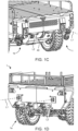
- the slave vehicle 1 can also be simultaneously articulated at the front end 1a thereof to the manned vehicle 2, and at the rear end thereof 1b to another slave vehicle 1, to form an articulated vehicle assembly 33 as seen in Fig. 2C .
- the another slave vehicle 1 can be articulated to yet another slave vehicle 1 at its free end, and so on, until driving in the manned vehicle 2 becomes too difficult for a driver thereof.
- Each of the articulated vehicle assemblies 13, 23, 33 enables independent driving thereof, i.e., without being articulated to any other vehicle. While at the assemblies 23,23 the master vehicle 2 is constantly the leading vehicle (expect while driving in reverse), at the assembly 13, any one of the slave vehicles 1 can be constituted as a leading vehicle.
- one or more slave vehicles 1 can drive to a destination while articulated to the master vehicle 2, and upon arrival, deploy, i.e., split, to individual units.
- Individual units including two or more slave vehicles 1 can drive independently at the destination to pre-determined deployment locations thereof, while individual units including a single slave vehicle 1 can reach their deployment locations articulated to the master vehicle 2 or to a master vehicle/one or more slave vehicles of another articulated vehicle assembly arriving to the destination.
- the modular slave vehicle 1 can include a self mobility aid system configured to facilitate independent limited maneuverability therefore, particularly for enabling an operator to slightly push or pull the modular slave vehicle 1 on top of comfortable ground and to a short distance, while the slave vehicle 1 is not articulated to any other vehicle.
- the slave structural frame can be constituted by another known in the art structure useful for supporting vehicles, e.g., a spaceframe, a unibody frame, etc.
- the chassis 10 has a rear end 10b and a front end 10a, and is configured to support the body 11 of the slave vehicle 1 within their boundaries. In other embodiments of the presently disclosed subject matter, the body 11 can extend beyond the chassis 10.
- the rear end 10b is mounted with two second slave vehicle couplings 15b, via which the slave vehicle 2 is configured to be articulated to another slave vehicle at its rear.
- the master coupling system 30 is mounted only to the front end 10a of the chassis 10, as the slave vehicle 1 is designed for driving forward at high speeds, i.e., in the direction D from the rear end 1b to the front end 1a thereof, and such high speeds are expected to be reached when the slave vehicle 1 is articulated to the master vehicle 2, which can be configured for driving independently at high speeds.
- the master coupling system 30 is designed to damp stresses being transmitted from the slave vehicle 1 to the manned vehicle 1, and vice versa.
- the damping herein is performed by partially allowing relative movement between the master vehicle 2 and the one or more slave vehicles 1 connected thereto, particularly by leaving some rotational Degrees Of Freedom therebetween unconstrained or partially constrained, as will be explained hereinafter.
- the first and second slave coupling devices 15a,15b are designed to connect with each other to form a tandem coupling 15 constraining all DOF between the vehicles.
- Such articulation renders the chassis 10 of the two or more slave vehicles 1 unified, and thereby facilitates a single area of free relative movement in the articulated vehicle assembly 33, i.e., between the master vehicle 2 and the first slave vehicle 1 connected thereto, contributing to the overall stability and intactness of the articulated vehicle assembly 33, particularly while driving at high speed and on rough terrain.
- Such articulation also contributes to stability and intactness of an articulated vehicle assembly consisting of two or more slave vehicles, such as the assembly 13 of Fig. 2A , and for the ability thereof to carry common load spreading between the vehicles, as will be explained hereinafter.
- each of the first slave coupling devices 15a is aligned with its respective second slave coupling device 15b, along a common longitudinal axis L1,L2, extending symmetrically on either side of a central longitudinal axis L of the slave vehicle 1.
- the slave vehicle 1 is a motorized vehicle having a driving system 20 with a motor (not seen) and road engaging members in form of two steerable and propellable wheels 22 operatively connected thereto at either side thereof.
- the driving system 20 enables the slave vehicle 1 to drive an articulated vehicle assembly consisting of slave vehicles, such as the assembly 13 of Fig. 2A , or ease articulated driving for the master vehicle 2, as will be explained hereinafter.
- any one of the driving systems 20 of the vehicles 1 can operate alone to propel the assembly 13 while the other is passive, or be operated in conjunction with the other driving system 20 to render the assembly 13 a 4X4 drive, depending on the operative need, and the control system available for operating the assembly 13.
- their driving system can facilitate nXn driving, where n stands for the number of wheels in the articulated vehicle assembly.
- the two wheels 22 herein are symmetrically aligned on either side of the slave vehicle 1, such that they share a common rotation axis R at a straight orientation thereof, seen in the figures.
- Having merely two wheels 22, contributes to the stability of the slave vehicle 1 during driving, as it limits the location of sudden impacts from the road.
- having merely two wheels in each slave vehicle 1 contributes to the overall stability of the assembly 23 as described.
- the distance of the wheels 22 from rear wheels 2' of the master vehicle 2 is also important for keeping the assembly 23 stable, and particularly may not exceed the distance between the rear wheels 2' of the master vehicle 2, and a front wheels 2" thereof.
- the wheels 22 of the slave vehicle 1 are fixed in their position, the distance between them and the rear wheels 2' of the master vehicle 2 is determined by the couplings therebeween, and between slave vehicles when more than one is articulated thereto.
- the master coupling system 30 has an operative length maintaining an offset distance OF1 between the front end 10a of the chassis 10 of the slave vehicle 1 and the coupling portion 2a of the manned vehicle 2.
- the tandem coupling 15 has a second operative length maintaining a second offset distance OF2 between the structural frames 10 of the respective slave vehicles 1 connected thereby.
- the second offset distance OF2 enables minor movements of non-structural elements of the two slave vehicles with respect to each other.
- FIG. 4 of the drawings showing a close up view of the stress absorbing coupling 30 as it articulates the slave vehicle 1 and the manned vehicle 2 together.
- the stress absorbing coupling 30 comprises three elongate members 31a, 31b, and 31c, where a length of which defines the offset distance OF1.
- the two side elongate members 31a and 31c being detachable from the slave vehicle 1, as seen in Fig. 5 , while the central elongate member 31b, constituted by a shaft 31b herein, is permanently welded to the chassis 10, protruding axially, i.e., along the longitudinal axis L of the slave vehicle 1, and particularly normally horizontally therefrom.
- the slave vehicle 1 is a directional vehicle configured to maintain a forward orientation, i.e., with the elongate members 31a,31b, and 31c protruding frontally thereto.
- those elongate members, and particularly the central elongate member 31b can interrupt close articulation of the slave vehicles 1.
- the slave vehicle 1 comprises an accommodation space 40, best seen in Fig. 6 , configured to accommodate the elongate members 31a,31c, and 31c, therein.
- Such arrangement allows the slave vehicle 1 to articulate with another slave vehicle 1 at its front, while maintaining the second offset distance OF2 between the vehicles chassis 10 shorter than the first offset distance OF1.
- the accommodation space 40 is disposed at the rear end 1b of the vehicle 1, with an opening 42 facing normally away from the rear end 1b.
- the openings 42 have dimensions corresponding to those of the elongate members 31a, 31b, and 31c, and are disposed at the same height as the elongate members 31a, 31b, 31c, with respect to a lowermost portion of the wheels 22.
- the horizontal length of the accommodation space 42 corresponds to the length of the elongate members 31a,31b,31c, and particularly to the length of the shaft 31b.
- the accommodation space 40 comprises a central protected zone 43 configured to receive and accommodate the central shaft 31b.
- the central protected zone 43 is bounded from below by a protective plate 43a protecting anything within the protected zone 43 from debris approaching from the ground.
- the accommodation space 40 further comprises two open areas 45 configured to accommodate the side elongate members 31a and 31c.
- the central shaft 31b being welded to the chassis 10, is a rigid structure which, during driving, should not be subject to bouncing relatively to the chassis 10, and therefore can be bounded within a protected space.
- the side elongate members 31a and 31c are detachably connectable to the chassis 10, as seen in Fig. 4B, and may even comprise flexible portions, are very much subject to bouncing and preforming any other form of relative movement with respect to the chassis 10 during driving.
- the open areas 45 have dimensions which are substantially greater than those of the elongate members 31a and 31c, and particularly corresponding to the expected disposition of the edges of the elongate members 31a and 31c, during driving.
- all three elongate members 31a, 31b, and 31c can be fixedly connected to the chassis 10, and the protective plate 43a can spread throughout the accommodation space 40, to define a greater protected area 43 capable of accommodating all three elongate members.
- the rear end 10b of the structural frame 10 has a different shape than the front end 10a thereof, namely, a shape bypassing the accommodation space 40.
- the rear end 10b of the structural frame 10 is higher than the front end 10a of the structural frame 10, so that the accommodation space 40 could be defined at the same height as the elongate members 31a,31b,31c, with respect to a lowermost portion of the wheels 22.
- the driving system 20 of one or more slave vehicles 1 can be adapted to not harm driving capabilities of the master vehicle 2, when the one or more slave vehicles 1 are articulated thereto.
- the slave vehicle 1 can be configured to drive at the same speed as the manned vehicle 2, to not damage acceleration and maximal speed of the master vehicle 2.
- the slave vehicle can also be configured to turn its wheels 22 in conjunction with the front wheels of 2" of the manned vehicle 2, to not damage the Instant center of rotation of the master vehicle 2.
- the driving system 20 of each of the slave vehicles 1 can be configured to consider the respective location of the slave vehicle on which it is mounted, i.e., the distance from the rear 2' wheels of the master vehicle 2, and adjust the rotation of its wheels 22 to not damage the natural ICOR of the master vehicle 2.
- the slave vehicle 1 can further comprise a control system 80 operatively connected to said driving system 20, so as to control driving thereof, as described hereinabove.
- the control system 80 can be configured, when the slave vehicle 1 is articulated directly or via one or more other slave vehicles such as 1 to the master vehicle 2, to drive the slave vehicle 1 based on the current position thereof with respect to the master vehicle 2, and optionally the type of master vehicle being used, particularly the distance between the steerable and non-steerable wheels thereof.
- the control system 80 is configured to 81 receive, optionally via a can-bus network, a first input signal indicative of a value of at least one driving parameter of the master vehicle 2, e.g., instant angle of rotation of its steerable wheels 2", and receive 82 a second input signal indicative of the number of slave vehicles between the master vehicle 2 and the slave vehicle 1 of the control system. In case where the slave vehicle 1 is articulated directly to the master vehicle 2, that number of vehicles would be 0.
- the control system 80 is further configured to process 83 those input signals, and produce in response instructions to the driving system 20, based on said processing, to adjust the value of a corresponding driving parameter, e.g., angle of wheels 22 of the slave vehicle 1, accordingly.
- the master vehicle comprises a monitoring system in communication with a can-bus network to which the control system 80 of the slave vehicle 1 can also connect.
- the can-bus network can share between the vehicles all necessary information for instructing the wheels of the slave vehicle 1.
- the control system 80 can be configured to receive a third input signal indicative of at least one dimension of the master vehicle, e.g., the distance between the front and rear wheels thereof 2", 2' and consider all three input signals during processing.
- control system 80 can be configured to consider all three inputs to determine the Instant Center Of Rotation of the master vehicle 2, and instruct the driving system 20 to steer the wheels 22 in a manner maintaining that for the entire articulated vehicle assembly.
- the distance between the wheels of the slave vehicle being articulated directly thereto, and the wheels of the rearmost slave vehicle should not exceed the distance between the front steerable wheels and the rear non steerable wheels of the master vehicle.
- the maximal number of slave vehicles articulable to the master vehicle 2 in a manner allowing comfortable driving therefore is two.
- the driving system 20 of one or more slave vehicles 1 can assist in driving the master vehicle 2, when the one or more slave vehicles 1 are articulated thereto.
- the mechanical stress absorbing coupling mechanism 30 is designed to allow free pitch movement, and partially restrict roll and yaw movements, of one vehicle with respect to the other, such that the vehicles articulated thereby are maintained aligned along the longitudinal axis L, while the translational DOF remain fully constrained.
- the mechanical stress absorbing coupling mechanism 13 is constituted by the articulation system disclosed in US 2020/0062306 .
- each of the stress absorbing coupling mechanism 13, the female coupling device 15a, and the male coupling device 15b is readily connectable to its respective coupling by a quick-connect mechanism, i.e., without performing any modifications thereof, without adding external parts to it, and optionally without using designated tools, thereby rendering the slave vehicle 1 a readily usable module for both uses abovementioned.
- Such quick-connect allows intuitive articulation and inarticulation of the slave vehicle 1 to the master vehicle 2 and to another slave vehicle 1, in field, by untrained personnel, rendering it suitable for combat missions.
- the tandem coupling 15 is constituted by a twistlock mechanism.
- the second coupling device 15b is constituted by a female, hollow casting 15b with an elongate hole 15b' in its front face 15b", while the first coupling device15a is constituted by a male, twistlock, having an elongate locking portion 15a' configured to be inserted through the hole 15a" and be rotated, optionally by 90°, within the hollo so it cannot be withdrawn out therefrom.
- the three elongate members 31a,31b, 31c each comprise a coupling head in the form of a hitch 31a', 31b', 31c', at its distal end from the vehicle 1, suitable for connection with a tow ball.
- the coupling portion 2a of the manned vehicle 2 includes three tow balls 2a' spaced apart to a distance corresponding to the distance between hitches 31a',31b',31c', to which the hitches are configured to connect.
- the coupling portion 2a can include any other means of articulation corresponding to the master coupling system 30 of the slave vehicle 1.
- the slave vehicle 1 herein is configured to carry load.
- the load can be in any form e.g., heavy military equipment such as antennas, radar devices, supply containers, etc.
- the load can be joined integrally to the slave vehicle 1, i.e., by welding thereof to the chassis 10 of the slave vehicle, or be detachably mounted thereto.
- the slave vehicle 1 comprises a load carrying platform 50 with a rear load carrying surface 50b extending above the rear end 10b of the chassis 10, and a front load carrying surface 50a extending above the front end 10a of the chassis.
- the two load carrying surfaces 50a and 50b are disposed at the same height with respect to the lowermost portion of the wheels 22, such that when two slave vehicles 1 are articulated to one another, as seen in Figs. 7A and 7B they form a common bed therebetween configured for carrying common load.
- the platform 50 is horizontally balanced such that all surfaces thereof are of the same height.
Landscapes
- Engineering & Computer Science (AREA)
- Transportation (AREA)
- Mechanical Engineering (AREA)
- Chemical & Material Sciences (AREA)
- Combustion & Propulsion (AREA)
- Body Structure For Vehicles (AREA)
- Air Bags (AREA)
- Vehicle Body Suspensions (AREA)
Description
- The present invention relates to auxiliary vehicles, particularly those configured for articulation with ordinary vehicles and other auxiliary vehicles.
- One example of a modular vehicle of the kind, to which the presently disclosed subject matter refers, is described in
DE 3009772 . -
US 2020/062306 Al discloses an articulated vehicle assembly comprising a master vehicle having a master steering system and an onboard sensor arrangement configured to monitor at least said master steering system; a slave vehicle having a slave steering system and an onboard actuator arrangement configured to manipulate at least said slave steering system; an articulation system for articulating in a queue the master and the slave vehicles along a common longitudinal axis; and a processing unit configured to receive input signals from the onboard sensor arrangement and produce corresponding output signals to the onboard actuator arrangement to manipulate said slave steering system so as to maintain the master vehicle and the slave vehicle aligned along the common longitudinal axis, at least when the master vehicle performs a turn on a horizontal plane. - According to the invention, there is provided a structural frame for use with a modular slave vehicle, said structural frame being simultaneously articulatable at rear end thereof to another structural frame of a modular slave vehicle, and at a front end thereof to a coupling portion of an independently driven master vehicle, said structural frame comprising:
a master coupling system in the form of a mechanical stress absorbing coupling mechanism mounted to said front end, said master coupling system being detachably articulatable to said coupling portion of the master vehicle so as to constrain, at least partially, all translational DOF of the vehicles relatively to each other, and leave at least one rotational DOF at least partially unconstrained;
characterized in that said structural frame further comprising: - at least one first slave coupling device mounted to said front end, distal from the master coupling system; and
- at least one second slave coupling device mounted to said rear end;
- said first and second coupling devices, when mounted to two adjacent structural frames intended to be connected to each other, are detachably connectable to each other to form a tandem coupling configured to constrain all DOF therebetween.
- According to a preferred embodiment, there is provided a modular slave vehicle articulatable at one end thereof to another slave vehicle and at another end thereof to an independently driven master vehicle having a coupling portion, simultaneously, said slave vehicle comprising:
- a body including a driving system for driving said slave vehicle;
- a slave structural frame supporting said body, wherein the slave structural frame is a structural frame according to the first aspect.
- Any one or more of the following features, designs and configurations can be applied to a modular slave vehicle and to a structural frame for use therewith, according to the present disclosure, separately or in various combinations thereof, as long as they fall under the scope of the appended claims:
The master coupling system can be configured to maintain a first offset distance between said slave vehicle and said master vehicle when the two are articulated thereby, and wherein said tandem coupling is configured to maintain a second offset distance between said structural frame of said slave vehicle and a structural frame of said another slave vehicle, when the two are articulated thereby, said second offset distance being smaller than said first offset distance. - The master coupling system can comprise a shaft mounted to said front end such that it permanently protrudes axially therefrom, said shaft having a length defining said first offset distance.
- The modular slave vehicle can further comprise an accommodation space closer to said rear end than said front end, configured to accommodate at least said shaft of said another slave vehicle, when the latter is articulated thereto.
- The accommodation space can be bounded, at least from below, by a protective plate configured to protect said shaft from debris approaching from the ground.
- The rear end of the structural frame can be higher than said front end thereof.
- The accommodation space can have a horizontal length corresponding to the first offset distance minus the second offset distance.
- The master coupling system can comprise three elongate members, each configured to connect independently to said coupling portion of said master vehicle, where a center elongate member is constituted by said shaft.
- Two side elongate members of said three elongate members can be detachable from said structural frame.
- The first and second slave coupling devices can be readily connectable to each other.
- The master coupling system can comprise means for quick-connection with the coupling portion.
- The means can include a hitch suitable for connection with a tow ball of said coupling portion.
- The tandem coupling can be configured to facilitate quick-connection between the first and second slave coupling devices.
- The tandem coupling can include a twistlock mechanism, and each of said first and second slave coupling devices comprises corresponding portions thereof.
- The first and second slave coupling devices can be aligned along a coupling longitudinal axis of the modular slave vehicle.
- The modular slave vehicle can further comprise a load carrying platform with a rear load carrying surface extending above said rear end of the structural frame, and a front load carrying surface extending above said front end of said structural frame, wherein said two load carrying surfaces are disposed at the same height with respect to said structural frame such that when two slave vehicles are articulated, they form a common bed therebetween.
- The modular slave vehicle according to any one of the preceding claims, wherein said at least one DOF being at least partially unconstrained allows free pitch movement between said master vehicle and said slave vehicle.
- The master coupling system can be configured to partially constrain roll movement between said master vehicle and slave vehicle.
- The master coupling system can be configured to constrain yaw movement of said slave vehicle with respect to said master vehicle.
- The master coupling system can be configured to maintain said master vehicle and said slave vehicle aligned along a common longitudinal axis.
- The driving system can comprise a road engaging arrangement consisting of a pair of wheels disposed on either side of the structural frame.
- The modular slave vehicle can further comprise a control system operatively connected to said driving system, said control system being configured, when said slave vehicle is articulated directly or via one or more slave vehicles to the master vehicle, to:
- receive a first input signal indicative of a value of at least one driving parameter of the master vehicle, and a second input signal indicative of the number of slave vehicles between the master vehicle and the slave vehicle of the control system;
- process said input signals; and
- produce instructions to said driving system, based on said processing, to adjust the value of a corresponding driving parameter of said slave vehicle accordingly.
- The control system can be configured to receive a third input signal indicative of at least one dimension of said master vehicle, and consider all three input signals during processing.
- The driving parameter can be an angle of rotation of at least one wheel of the respective vehicle.
- In order to better understand the subject matter that is disclosed herein and to exemplify how it may be carried out in practice, embodiments will now be described, by way of non-limiting example only, with reference to the accompanying drawings, in which:
-
Fig. 1A is top perspective view of a modular slave vehicle according to one example of the recently disclosed subject matter; -
Fig. 1B is a side view of the modular slave vehicle ofFig. 1A ; -
Fig. 1C is a rear perspective view of the modular slave vehicle ofFig. 1A ; -
Fig. 1D is a front perspective view of the modular slave vehicle ofFig. 1A ; -
Fig. 2A is a side view of an articulated vehicle assembly comprising two slave vehicles as the slave vehicle ofFig. 1A ; -
Fig. 2B is a rear perspective view of an articulated vehicle assembly comprising a master vehicle and the slave vehicle ofFig. 1A ; -
Fig. 2C is a side view of an articulate vehicle assembly comprising a master vehicle and two slave vehicles ofFig. 1A ; -
Fig. 3 is a top perspective view of a structural frame of the slave vehicle ofFig. 1A ; -
Fig. 4 is a front perspective view of a master coupling system of the slave vehicle ofFig. 1A ; -
Fig. 5 is a front perspective view of the slave vehicle ofFig. 1A with two elongate members of the coupling system ofFig. 4 detached therefrom; -
Fig. 6 is a bottom view of twoslave vehicles 1 articulated to one another, with the master coupling system of one vehicle received within an accommodation space of the other vehicle. -
Fig. 7A is a top perspective view of two slave vehicles articulated to one another such that their load carrying platforms form a common bed together; -
Fig. 7B is a top perspective view of three slave vehicles articulated to one another such that their load carrying platforms form a common bed together; and -
Fig. 8 is a schematic flow chart demonstrating the operation of a control system of the slave vehicle ofFig. 1A . - Attention is first directed towards
Figs. 1 and2 of the drawings illustrating amodular slave vehicle 1, according to an example of the presently disclosed subject matter. - The
slave vehicle 1 is a motorized load carrying vehicle, constituting a module for use in an articulated vehicle assembly including two or more vehicles, as illustrated inFigs. 2A to 2C . - In particular, the
modular slave vehicle 1 is configured for dual use, i.e. for articulating at afront end 1a thereof as a trailer to an ordinary state of the art master vehicle, or to a slightly modified state of theart vehicle 2, to form an articulatedvehicle assembly 23 as seen inFig. 2B , and for articulating at thefront end 1a thereof and/or at arear end 1b thereof, as either a trailer or a lead vehicle, to another, identical,slave vehicle 1, to form an articulatedvehicle assembly 13 consisting of slave vehicles as seen inFig. 2A . - The
master vehicle 2 can be manned or unmanned, and can be articulated to theslave vehicle 1 via acoupling portion 2a thereof, of which an example will be described hereinafter in more detail. - The
slave vehicle 1 can also be simultaneously articulated at thefront end 1a thereof to the mannedvehicle 2, and at therear end thereof 1b to anotherslave vehicle 1, to form an articulatedvehicle assembly 33 as seen inFig. 2C . - In turn, the another
slave vehicle 1 can be articulated to yet anotherslave vehicle 1 at its free end, and so on, until driving in the mannedvehicle 2 becomes too difficult for a driver thereof. - Each of the articulated
vehicle assemblies assemblies master vehicle 2 is constantly the leading vehicle (expect while driving in reverse), at theassembly 13, any one of theslave vehicles 1 can be constituted as a leading vehicle. - It should be appreciated that the
slave vehicle 1 is configured for military purposes, i.e., configured to be functional for off-road articulated driving at high speeds. When too many slave vehicles are articulated to the mannedvehicle 2, driving off-road at high speed may cause instabilities in the articulated vehicle assembly. - With such arrangement, one or
more slave vehicles 1 can drive to a destination while articulated to themaster vehicle 2, and upon arrival, deploy, i.e., split, to individual units. Individual units including two ormore slave vehicles 1 can drive independently at the destination to pre-determined deployment locations thereof, while individual units including asingle slave vehicle 1 can reach their deployment locations articulated to themaster vehicle 2 or to a master vehicle/one or more slave vehicles of another articulated vehicle assembly arriving to the destination. - It should be appreciated that the
modular slave vehicle 1 can include a self mobility aid system configured to facilitate independent limited maneuverability therefore, particularly for enabling an operator to slightly push or pull themodular slave vehicle 1 on top of comfortable ground and to a short distance, while theslave vehicle 1 is not articulated to any other vehicle. - The
slave vehicle 1 comprises a slave structural frame, here in the form of chassis 10 (seen in greater detail inFig. 3 ), supporting abody 11 thereof and mounted with a plurality of coupling devices and mechanisms, as will be explained hereinafter. - In other embodiments of the presently disclosed subject matter, the slave structural frame can be constituted by another known in the art structure useful for supporting vehicles, e.g., a spaceframe, a unibody frame, etc.
- The
chassis 10 has arear end 10b and afront end 10a, and is configured to support thebody 11 of theslave vehicle 1 within their boundaries. In other embodiments of the presently disclosed subject matter, thebody 11 can extend beyond thechassis 10. - The
front end 10a is mounted with a master coupling system in the form of a mechanical stress absorbingcoupling mechanism 30, via which theslave vehicle 1 is configured to detachably articulate to themaster vehicle 2, (seen in greater detail inFig. 4 ) and with two firstslave coupling devices 15a, via which theslave vehicle 1 is configured to be articulated to anotherslave vehicle 1 at its front, while not articulated to themaster vehicle 2. - The
rear end 10b is mounted with two secondslave vehicle couplings 15b, via which theslave vehicle 2 is configured to be articulated to another slave vehicle at its rear. - As can be understood, the
master coupling system 30 is mounted only to thefront end 10a of thechassis 10, as theslave vehicle 1 is designed for driving forward at high speeds, i.e., in the direction D from therear end 1b to thefront end 1a thereof, and such high speeds are expected to be reached when theslave vehicle 1 is articulated to themaster vehicle 2, which can be configured for driving independently at high speeds. - For enabling comfortable driving for the manned
vehicle 2 while one or more slave vehicles, such asslave vehicle 1, are articulated thereto, themaster coupling system 30 is designed to damp stresses being transmitted from theslave vehicle 1 to the mannedvehicle 1, and vice versa. The damping herein is performed by partially allowing relative movement between themaster vehicle 2 and the one ormore slave vehicles 1 connected thereto, particularly by leaving some rotational Degrees Of Freedom therebetween unconstrained or partially constrained, as will be explained hereinafter. - To further enable comfortable driving of the
master vehicle 2 when articulated to two or more slave vehicles, as in theassembly 33 ofFig. 2C , the first and secondslave coupling devices tandem coupling 15 constraining all DOF between the vehicles. - Such articulation renders the
chassis 10 of the two ormore slave vehicles 1 unified, and thereby facilitates a single area of free relative movement in the articulatedvehicle assembly 33, i.e., between themaster vehicle 2 and thefirst slave vehicle 1 connected thereto, contributing to the overall stability and intactness of the articulatedvehicle assembly 33, particularly while driving at high speed and on rough terrain. - Such articulation also contributes to stability and intactness of an articulated vehicle assembly consisting of two or more slave vehicles, such as the
assembly 13 ofFig. 2A , and for the ability thereof to carry common load spreading between the vehicles, as will be explained hereinafter. - To be able to connect when mounted to two
identical slave vehicles 1, each of the firstslave coupling devices 15a is aligned with its respective secondslave coupling device 15b, along a common longitudinal axis L1,L2, extending symmetrically on either side of a central longitudinal axis L of theslave vehicle 1. - It should be appreciated that the
slave vehicle 1 is a motorized vehicle having a drivingsystem 20 with a motor (not seen) and road engaging members in form of two steerable andpropellable wheels 22 operatively connected thereto at either side thereof. The drivingsystem 20 enables theslave vehicle 1 to drive an articulated vehicle assembly consisting of slave vehicles, such as theassembly 13 ofFig. 2A , or ease articulated driving for themaster vehicle 2, as will be explained hereinafter. - As such, in an assembly of two or more slave vehicles, as the
assembly 13 ofFig. 2a , any one of the drivingsystems 20 of thevehicles 1 can operate alone to propel theassembly 13 while the other is passive, or be operated in conjunction with theother driving system 20 to render the assembly 13 a 4X4 drive, depending on the operative need, and the control system available for operating theassembly 13. In general, when more than twoslave vehicles 1 are articulated together to form an articulated vehicle assembly, their driving system can facilitate nXn driving, where n stands for the number of wheels in the articulated vehicle assembly. - In other embodiments of the presently disclosed subject matter the road engaging members can be constituted by caterpillar tracks, ski slides, or any other known road engaging member useful for advancing vehicles.
- The two
wheels 22 herein are symmetrically aligned on either side of theslave vehicle 1, such that they share a common rotation axis R at a straight orientation thereof, seen in the figures. - Having merely two
wheels 22, contributes to the stability of theslave vehicle 1 during driving, as it limits the location of sudden impacts from the road. When one ormore slave vehicles 1 are articulated to themaster vehicle 2, as in theassembly 23, having merely two wheels in eachslave vehicle 1 contributes to the overall stability of theassembly 23 as described. Further, the distance of thewheels 22 from rear wheels 2' of themaster vehicle 2, is also important for keeping theassembly 23 stable, and particularly may not exceed the distance between the rear wheels 2' of themaster vehicle 2, and afront wheels 2" thereof. As thewheels 22 of theslave vehicle 1 are fixed in their position, the distance between them and the rear wheels 2' of themaster vehicle 2 is determined by the couplings therebeween, and between slave vehicles when more than one is articulated thereto. - As can be seen in the figures, the
master coupling system 30 has an operative length maintaining an offset distance OF1 between thefront end 10a of thechassis 10 of theslave vehicle 1 and thecoupling portion 2a of the mannedvehicle 2. - The offset distance OF1 enables pitch of one vehicle towards the other, and facilitates length for damping stresses passing between the vehicles.
- As can be also seen in the figures, the
tandem coupling 15 has a second operative length maintaining a second offset distance OF2 between thestructural frames 10 of therespective slave vehicles 1 connected thereby. The second offset distance OF2 enables minor movements of non-structural elements of the two slave vehicles with respect to each other. - To facilitate comfortable driving in the
master vehicle 2 when two ormore slave vehicles 1 are articulated thereto, the two offset distances, and particularly the second offset distance OF2 should be minimal as possible, much shorter than the offset distance OF1, and particularly minimal to allow the rotation axes R of thewheels 22 of therespective slave vehicles 1 to come as close together as possible, and thereby increase the stability of the entire structure, particularly at high speeds, and limit the development of moment forces throughout the along the articulated vehicle assembly. - Attention is now directed to
Fig. 4 of the drawings, showing a close up view of thestress absorbing coupling 30 as it articulates theslave vehicle 1 and the mannedvehicle 2 together. - As can be seen, the
stress absorbing coupling 30 comprises threeelongate members - The two side
elongate members slave vehicle 1, as seen inFig. 5 , while the centralelongate member 31b, constituted by ashaft 31b herein, is permanently welded to thechassis 10, protruding axially, i.e., along the longitudinal axis L of theslave vehicle 1, and particularly normally horizontally therefrom. - As mentioned, the
slave vehicle 1 is a directional vehicle configured to maintain a forward orientation, i.e., with theelongate members - As such, in an articulated vehicle assembly of two or more slave vehicles, those elongate members, and particularly the central
elongate member 31b, can interrupt close articulation of theslave vehicles 1. - For overcoming such, the
slave vehicle 1 comprises anaccommodation space 40, best seen inFig. 6 , configured to accommodate theelongate members slave vehicle 1 to articulate with anotherslave vehicle 1 at its front, while maintaining the second offset distance OF2 between thevehicles chassis 10 shorter than the first offset distance OF1. - The
accommodation space 40 is disposed at therear end 1b of thevehicle 1, with anopening 42 facing normally away from therear end 1b. To accommodate the elongate members, theopenings 42 have dimensions corresponding to those of theelongate members elongate members wheels 22. To facilitate maximal accommodation therein, the horizontal length of theaccommodation space 42 corresponds to the length of theelongate members shaft 31b. - The
accommodation space 40 comprises a central protectedzone 43 configured to receive and accommodate thecentral shaft 31b. The central protectedzone 43 is bounded from below by aprotective plate 43a protecting anything within the protectedzone 43 from debris approaching from the ground. - The
accommodation space 40 further comprises twoopen areas 45 configured to accommodate the sideelongate members central shaft 31b, being welded to thechassis 10, is a rigid structure which, during driving, should not be subject to bouncing relatively to thechassis 10, and therefore can be bounded within a protected space. On the other hand, the sideelongate members chassis 10, as seen in Fig. 4B, and may even comprise flexible portions, are very much subject to bouncing and preforming any other form of relative movement with respect to thechassis 10 during driving. - As such, the
open areas 45 have dimensions which are substantially greater than those of theelongate members elongate members - In other embodiments of the presently disclosed subject matter, all three
elongate members chassis 10, and theprotective plate 43a can spread throughout theaccommodation space 40, to define a greater protectedarea 43 capable of accommodating all three elongate members. - To facilitate that
accommodation space 40, therear end 10b of thestructural frame 10 has a different shape than thefront end 10a thereof, namely, a shape bypassing theaccommodation space 40. Herein, therear end 10b of thestructural frame 10 is higher than thefront end 10a of thestructural frame 10, so that theaccommodation space 40 could be defined at the same height as theelongate members wheels 22. - It should be appreciated that the driving
system 20 of one ormore slave vehicles 1 can be adapted to not harm driving capabilities of themaster vehicle 2, when the one ormore slave vehicles 1 are articulated thereto. - In particular, the
slave vehicle 1 can be configured to drive at the same speed as themanned vehicle 2, to not damage acceleration and maximal speed of themaster vehicle 2. The slave vehicle can also be configured to turn itswheels 22 in conjunction with the front wheels of 2" of the mannedvehicle 2, to not damage the Instant center of rotation of themaster vehicle 2. When more than oneslave vehicle 1 is connected to themaster vehicle 2, the drivingsystem 20 of each of theslave vehicles 1 can be configured to consider the respective location of the slave vehicle on which it is mounted, i.e., the distance from the rear 2' wheels of themaster vehicle 2, and adjust the rotation of itswheels 22 to not damage the natural ICOR of themaster vehicle 2. - The
slave vehicle 1 can further comprise a control system 80 operatively connected to said drivingsystem 20, so as to control driving thereof, as described hereinabove. - The control system 80, having an operational flow described in
Fig. 8 , can be configured, when theslave vehicle 1 is articulated directly or via one or more other slave vehicles such as 1 to themaster vehicle 2, to drive theslave vehicle 1 based on the current position thereof with respect to themaster vehicle 2, and optionally the type of master vehicle being used, particularly the distance between the steerable and non-steerable wheels thereof. in particular, the control system 80 is configured to 81 receive, optionally via a can-bus network, a first input signal indicative of a value of at least one driving parameter of themaster vehicle 2, e.g., instant angle of rotation of itssteerable wheels 2", and receive 82 a second input signal indicative of the number of slave vehicles between themaster vehicle 2 and theslave vehicle 1 of the control system. In case where theslave vehicle 1 is articulated directly to themaster vehicle 2, that number of vehicles would be 0. - The control system 80 is further configured to process 83 those input signals, and produce in response instructions to the driving
system 20, based on said processing, to adjust the value of a corresponding driving parameter, e.g., angle ofwheels 22 of theslave vehicle 1, accordingly. - According to an example of the presently disclosed subject matter, the master vehicle comprises a monitoring system in communication with a can-bus network to which the control system 80 of the
slave vehicle 1 can also connect. In such a case, the can-bus network can share between the vehicles all necessary information for instructing the wheels of theslave vehicle 1. According to that example, the control system 80 can be configured to receive a third input signal indicative of at least one dimension of the master vehicle, e.g., the distance between the front and rear wheels thereof 2", 2' and consider all three input signals during processing. - In general, the control system 80 can be configured to consider all three inputs to determine the Instant Center Of Rotation of the
master vehicle 2, and instruct thedriving system 20 to steer thewheels 22 in a manner maintaining that for the entire articulated vehicle assembly. - As such, for a master vehicle having non-steerable rear wheels, such as the
vehicle 2, to be able to drive comfortably, the distance between the wheels of the slave vehicle being articulated directly thereto, and the wheels of the rearmost slave vehicle, should not exceed the distance between the front steerable wheels and the rear non steerable wheels of the master vehicle. - In the examples shown herein, the maximal number of slave vehicles articulable to the
master vehicle 2 in a manner allowing comfortable driving therefore is two. - It should be further appreciated that by means of the
master coupling system 30, the drivingsystem 20 of one ormore slave vehicles 1 can assist in driving themaster vehicle 2, when the one ormore slave vehicles 1 are articulated thereto. - In particular, the mechanical stress absorbing
coupling mechanism 30 is designed to allow free pitch movement, and partially restrict roll and yaw movements, of one vehicle with respect to the other, such that the vehicles articulated thereby are maintained aligned along the longitudinal axis L, while the translational DOF remain fully constrained. - The constraining of translational DOF's allows the
slave vehicle 1 to hold back themaster vehicle 2 using its brakes, while the restriction of yaw and roll movements allows theslave vehicle 1 to push themaster vehicle 2. - According to an example of the presently disclosed subject matter, the mechanical stress absorbing
coupling mechanism 13 is constituted by the articulation system disclosed inUS 2020/0062306 . - It should be appreciated that each of the stress absorbing
coupling mechanism 13, thefemale coupling device 15a, and themale coupling device 15b, is readily connectable to its respective coupling by a quick-connect mechanism, i.e., without performing any modifications thereof, without adding external parts to it, and optionally without using designated tools, thereby rendering theslave vehicle 1 a readily usable module for both uses abovementioned. - Such quick-connect allows intuitive articulation and inarticulation of the
slave vehicle 1 to themaster vehicle 2 and to anotherslave vehicle 1, in field, by untrained personnel, rendering it suitable for combat missions. - In the examples shown herein, the
tandem coupling 15 is constituted by a twistlock mechanism. Thesecond coupling device 15b is constituted by a female,hollow casting 15b with anelongate hole 15b' in itsfront face 15b", while the first coupling device15a is constituted by a male, twistlock, having anelongate locking portion 15a' configured to be inserted through thehole 15a" and be rotated, optionally by 90°, within the hollo so it cannot be withdrawn out therefrom. - Similarly, the three
elongate members hitch 31a', 31b', 31c', at its distal end from thevehicle 1, suitable for connection with a tow ball. - In turn, the
coupling portion 2a of the mannedvehicle 2, includes threetow balls 2a' spaced apart to a distance corresponding to the distance betweenhitches 31a',31b',31c', to which the hitches are configured to connect. - It should be appreciated that although most ordinary vehicles typically include 1 tow ball or no tow ball at all, modifying an ordinary vehicle to include such, is relatively easy to perform, particularly when compared to modifying a vehicle to include equipment which can be carried by the
slave vehicle 1, e.g., military antenna. As such, theslave vehicle 1 redundance the need for extreme modification of vehicles to be able to carry particular load, as it can carry the load in itself and be connected to any slightly modified ordinary vehicle. - In other embodiments of the presently disclosed subject matter the
coupling portion 2a can include any other means of articulation corresponding to themaster coupling system 30 of theslave vehicle 1. - The
slave vehicle 1 herein is configured to carry load. The load can be in any form e.g., heavy military equipment such as antennas, radar devices, supply containers, etc. The load can be joined integrally to theslave vehicle 1, i.e., by welding thereof to thechassis 10 of the slave vehicle, or be detachably mounted thereto. - To facilitate carrying of detachable load, the
slave vehicle 1 comprises aload carrying platform 50 with a rearload carrying surface 50b extending above therear end 10b of thechassis 10, and a frontload carrying surface 50a extending above thefront end 10a of the chassis. As can be seen in the figures, the twoload carrying surfaces wheels 22, such that when twoslave vehicles 1 are articulated to one another, as seen inFigs. 7A and 7B they form a common bed therebetween configured for carrying common load. - In the example shown herein, the
platform 50 is horizontally balanced such that all surfaces thereof are of the same height.
Claims (15)
- A structural frame (10) for use with a modular slave vehicle (1), said structural frame being simultaneously articulatable at a rear end (10b) thereof to another structural frame of a modular slave vehicle (1), and at a front end (10a) thereof to a coupling portion of an independently driven master vehicle, said structural frame comprising:
a master coupling system (30) in the form of a mechanical stress absorbing coupling mechanism mounted to said front end (10a), said master coupling system being detachably articulatable to said coupling portion of the master vehicle so as to constrain, at least partially, all translational DOF of the vehicles relatively to each other, and leave at least one rotational DOF at least partially unconstrained;
characterized in that said structural frame further comprises:at least one first slave coupling device (15a) mounted to said front end (10a), distal from the master coupling system (30); andat least one second slave coupling device (15b) mounted to said rear end (10b);said first and second coupling devices (15a, 15b), when mounted to two adjacent structural frames intended to be connected to each other, are detachably connectable to each other to form a tandem coupling (15) configured to constrain all DOF therebetween. - A modular slave vehicle (1) articulatable at one end thereof to another slave vehicle and at another end thereof to an independently driven master vehicle (2) having a coupling portion, simultaneously, said slave vehicle comprising:a body (11) including a driving system for driving said slave vehicle;a slave structural frame (10) supporting said body, wherein the slave structural frame is a structural frame according to claim 1.
- The modular slave vehicle according to Claim 2, wherein said master coupling system is configured to maintain a first offset distance (OF1) between said slave vehicle (1) and said master vehicle (2) when the two are articulated thereby, and wherein said tandem coupling (15) is configured to maintain a second offset distance (OF2) between said structural frame (10) of said slave vehicle and a structural frame (10) of said another slave vehicle, when the two are articulated thereby, said second offset distance being smaller than said first offset distance.
- The modular slave vehicle according to Claim 3, wherein said master coupling system comprises a shaft (31a, 31b, 31c) mounted to said front end (10a) such that it permanently protrudes axially therefrom, said shaft having a length defining said first offset distance.
- The modular slave vehicle according to Claim 4, further comprising an accommodation space (40) closer to said rear end than said front end, configured to accommodate at least said shaft (31a, 31b, 31c) of said another slave vehicle, when the latter is articulated thereto.
- The modular slave vehicle according to Claim 5, wherein said accommodation space (40) is bounded, at least from below, by a protective plate (43a) configured to protect said shaft from debris approaching from the ground.
- The modular slave vehicle according to one of the preceding claims 2 to 6, wherein said rear end (10b) of said structural frame (10) is higher than said front end (10a) thereof.
- The modular slave vehicle according to one of the preceding claims 2 to 7, wherein said master coupling system (30) comprises three elongate members (31a, 31b, 31c), each configured to connect independently to said coupling portion of said master vehicle, where a center elongate member is constituted by said shaft.
- The modular slave vehicle according to Claim 8, wherein two side elongate members (31a, 31b, 31c) of said three elongate members are detachable from said structural frame.
- The modular slave vehicle according to one of the preceding claims 2 to 9, wherein said first and second slave coupling devices (15a, 15b) are aligned along a coupling longitudinal axis of the modular slave vehicle.
- The modular slave vehicle according to one of the preceding claims 2 to 10, further comprising a load carrying platform (50) with a rear load carrying surface extending above said rear end of the structural frame, and a front load carrying surface extending above said front end of said structural frame, wherein said two load carrying surfaces are disposed at the same height with respect to said structural frame such that when two slave vehicles are articulated, they form a common bed therebetween.
- The modular slave vehicle according to one of the preceding claims 2 to 11, wherein said at least one DOF being at least partially unconstrained allows free pitch movement between said master vehicle and said slave vehicle.
- The modular slave vehicle according to one of the preceding claims 2 to 12, further comprising a control system (80) operatively connected to said driving system, said control system being configured, when said slave vehicle (1) is articulated directly or via one or more slave vehicles to the master vehicle (2), to:receive a first input signal indicative of a value of at least one driving parameter of the master vehicle (2), and a second input signal indicative of the number of slave vehicles between the master vehicle and the slave vehicle of the control system;process said input signals; andproduce instructions to said driving system, based on said processing, to adjust the value of a corresponding driving parameter of said slave vehicle accordingly.
- The modular slave vehicle according to Claim 13, wherein said control system (80) is configured to receive a third input signal indicative of at least one dimension of said master vehicle (2), and consider all three input signals during processing.
- The modular slave vehicle according to Claim 14, wherein said driving parameter is an angle of rotation of at least one wheel of the respective vehicle.
Applications Claiming Priority (1)
| Application Number | Priority Date | Filing Date | Title |
|---|---|---|---|
| IL283075A IL283075A (en) | 2021-05-10 | 2021-05-10 | Dual use trailer vehicle |
Publications (3)
| Publication Number | Publication Date |
|---|---|
| EP4088954A1 EP4088954A1 (en) | 2022-11-16 |
| EP4088954B1 true EP4088954B1 (en) | 2025-01-29 |
| EP4088954C0 EP4088954C0 (en) | 2025-01-29 |
Family
ID=81597933
Family Applications (1)
| Application Number | Title | Priority Date | Filing Date |
|---|---|---|---|
| EP22172475.0A Active EP4088954B1 (en) | 2021-05-10 | 2022-05-10 | Dual use trailer vehicle |
Country Status (4)
| Country | Link |
|---|---|
| US (2) | US11945529B2 (en) |
| EP (1) | EP4088954B1 (en) |
| AU (1) | AU2022203107A1 (en) |
| IL (1) | IL283075A (en) |
Family Cites Families (131)
| Publication number | Priority date | Publication date | Assignee | Title |
|---|---|---|---|---|
| US2962176A (en) * | 1957-08-29 | 1960-11-29 | Joy Mfg Co | Low height shuttle car |
| US3000651A (en) | 1960-09-12 | 1961-09-19 | Gouirand Rene | Pneumatic suspension for vehicles with means for preventing undue sway of the vehicle |
| US3414072A (en) | 1965-09-16 | 1968-12-03 | Lockheed Aircraft Corp | Vehicle capable of articulating about roll, pitch, and yaw axes |
| US3353618A (en) | 1965-09-27 | 1967-11-21 | Fisher Alfred Gordon | Articulated vehicle |
| GB1229261A (en) | 1967-06-12 | 1971-04-21 | ||
| US3578096A (en) | 1968-06-25 | 1971-05-11 | Chester T Pearson | Automatic throttle control for auxiliary motors driving drawbar-towed vehicles |
| FR2062911A1 (en) | 1969-10-30 | 1971-07-02 | Jakovenko Marinitch Vlad | |
| US3717215A (en) | 1970-11-30 | 1973-02-20 | Us Army | Cross-country vehicle |
| US3669469A (en) * | 1970-12-28 | 1972-06-13 | Volvo Ab | Articulated vehicle frame |
| US3899039A (en) | 1973-02-22 | 1975-08-12 | John Mchugh | Bus having a separate wheeled motive power unit |
| DE2547362A1 (en) | 1975-10-20 | 1977-04-21 | Albert Solewski | Electric traction selectively coupled to car - with two wheeled battery powered trolley hooked to rear coupling and controlled from dashboard |
| US4033426A (en) | 1976-01-15 | 1977-07-05 | Williams Eugene J | Apparatus for steering trailer vehicles |
| US4072203A (en) | 1976-05-14 | 1978-02-07 | Pierson Neil W | Small, personal, all terrain vehicle |
| US4119166A (en) * | 1977-07-01 | 1978-10-10 | General Motors Corporation | Dual-vehicle operating system |
| FR2460223A1 (en) | 1979-06-29 | 1981-01-23 | Baudouin Moteurs | Lift for vehicle body side - has screw jack head which fits in support on body underside and bringing jack vertical by movement |
| DE3009772A1 (en) | 1980-03-14 | 1981-09-24 | Walter Steinhardt | Drive unit for coupling to vehicle - has chassis with wheel driven via gear from DC motor supplied from battery |
| FR2482528A1 (en) | 1980-05-14 | 1981-11-20 | Heuliez Henri Holding | MOTOR VEHICLE HAVING TWO TRACTION MODES, IN PARTICULAR AUTOBUS |
| DE3143723A1 (en) | 1981-11-04 | 1983-05-11 | Willy Scheuerle Fahrzeugfabrik GmbH & Co, 7114 Pfedelbach | "HEAVY LOAD VEHICLE COMBINATION OR VEHICLE ASSOCIATION" |
| US4502561A (en) | 1981-12-15 | 1985-03-05 | Alois Kober Ag | Tractor-trailer combination with a coupling connection |
| EP0092952A1 (en) | 1982-04-19 | 1983-11-02 | Sir Rupert Edward MANN & Lady Mary Rose MANN | Land vehicle |
| EP0197030A1 (en) | 1984-10-03 | 1986-10-15 | ANDERSON, Rogers H. | Powered trailer |
| CH665178A5 (en) | 1984-10-30 | 1988-04-29 | Bucher Guyer Ag Masch | TRAIN VEHICLE WITH DRIVE AXLE TRAILER. |
| US4650018A (en) | 1985-03-15 | 1987-03-17 | Silverman Sr Milton J | Combination vehicle assembly |
| FR2580998B1 (en) | 1985-04-26 | 1989-10-20 | Woestelandt Emile | HITCH STRUCTURE BETWEEN A TRACTOR VEHICLE AND A TRACTOR VEHICLE |
| US4771838A (en) | 1987-05-21 | 1988-09-20 | Ketcham George M | Obedient self-powered slave vehicles |
| DE3829638A1 (en) | 1987-11-25 | 1989-06-08 | Schoell Guenter | Motor vehicle |
| US5002528A (en) | 1989-12-15 | 1991-03-26 | Aubrey Palestrant | Percutaneous irrigation and drainage system |
| US5165838A (en) | 1990-09-06 | 1992-11-24 | Teledyne Industries, Inc. | Vehicle for transporting loads |
| US5330020A (en) | 1991-06-03 | 1994-07-19 | Ketcham George M | Self-powered towing servomechanism |
| FR2696130B1 (en) | 1992-09-28 | 1994-12-16 | Lemaitre Jean Pierre | Device to facilitate the reversing of a road train. |
| US5332052A (en) | 1992-10-19 | 1994-07-26 | Louis Carnevale | Detachable all terrain trailer |
| DE4324211A1 (en) | 1993-07-19 | 1995-01-26 | Linde Ag | Method for operating a vehicle drive or a towing or pushing, or a towed or pushed, vehicle and vehicle provided for the method |
| JP3361275B2 (en) | 1998-06-24 | 2003-01-07 | 株式会社 ヴァリアス | Camping self-propelled trailer dump |
| WO2003022665A1 (en) | 1999-10-14 | 2003-03-20 | Gulf Transp Co Pty Ltd | Multi-combination vehicle incorporating a power trailer |
| US6725955B2 (en) | 1999-10-08 | 2004-04-27 | John L. Bidwell | Powered trailer to propel a two wheeled vehicle |
| US6419037B1 (en) | 2000-07-19 | 2002-07-16 | Meritor Heavy Vehicle Systems, Llc | Multi-unit articulated road train propulsion system |
| US6746037B1 (en) | 2000-12-20 | 2004-06-08 | Craig A. Kaplenski | Trailer hitch with multi-directional dampening system and spherical rod-end assembly |
| US20030090083A1 (en) | 2001-11-13 | 2003-05-15 | Williams Ronald G. | Supplemental trailer hitch for backing |
| AU2002312638B1 (en) | 2002-05-24 | 2003-12-12 | BIS Industries Ltd | System for the control of multiple transmission in a multi-combination vehicle |
| US9764748B2 (en) | 2016-01-21 | 2017-09-19 | General Electric Company | Vehicle control system |
| AU2003303903B2 (en) | 2003-02-19 | 2009-03-26 | BIS Industries Ltd | System for the control of multiple engines in a multi-combination vehicle having independent throttle controls when under emergency braking |
| WO2004074032A1 (en) | 2003-02-21 | 2004-09-02 | Cooper, James, W. | System for the control of multiple engines having independent throttle controls in a vehicle when driver becomes ineffective |
| US6880651B2 (en) | 2003-05-14 | 2005-04-19 | Singapore Technologies Kinetics Ltd. | Articulated vehicle, an articulation device and a drive transmission |
| CA2463044A1 (en) | 2004-04-02 | 2005-10-02 | H. William B. Wilt | Method of making a modular vehicle and a modular vehicle |
| MX2007000966A (en) | 2004-07-23 | 2007-07-11 | Belemark S A | High tonnage ultra light mining truck. |
| US7115070B2 (en) | 2004-10-18 | 2006-10-03 | James W. Cooper | System for the control of multiple engines in a multi-combination vehicle having independent throttle controls when under emergency braking |
| US20060085117A1 (en) | 2004-10-18 | 2006-04-20 | Stummer Mark J | System for the control of multiple engines having independent throttle controls in a vehicle when driver becomes ineffective |
| US7514803B2 (en) | 2005-08-18 | 2009-04-07 | Wilks Paul L | Trailer with integral axle-mounted generator and battery charger |
| IL172078A (en) | 2005-11-21 | 2010-11-30 | Univ Ariel Res & Dev Co Ltd | Dual tracked mobile robot for motion in rough terrain |
| DE102005057652A1 (en) | 2005-12-01 | 2007-08-16 | Kuka Roboter Gmbh | vehicle network |
| WO2007070988A1 (en) | 2005-12-21 | 2007-06-28 | Cooper James W | A power dolly and a multicombination vehicle including a power dolly |
| US7743859B2 (en) | 2006-02-03 | 2010-06-29 | Magna Powertrain Usa, Inc. | Hybrid drivetrains for trailers |
| US7547980B2 (en) | 2006-02-10 | 2009-06-16 | Roger Harrison | Power generating unit on semi-trailer for energy recovery and storage |
| US8538608B2 (en) | 2009-09-09 | 2013-09-17 | General Electric Company | Control system and method for remotely isolating powered units in a rail vehicle system |
| US7798263B2 (en) | 2006-05-03 | 2010-09-21 | Tandy Engineering & Associates, Inc. | Stability enhancing system for tow-vehicle and trailer assembly combination with two processors |
| FR2901233B1 (en) | 2006-05-17 | 2009-02-27 | Eurolum Soc Par Actions Simpli | WHEEL VEHICLE, COUPLING METHOD, DAMAGING METHOD, METHOD OF MANAGING THE VEHICLE AND TRAIN OF RESULTING VEHICLES |
| DE102006030347A1 (en) | 2006-06-30 | 2008-01-03 | Daimlerchrysler Ag | Trailer for attaching to a truck comprises a steering actuator for adjusting the steering angle on steerable wheels |
| US20080238138A1 (en) | 2007-03-27 | 2008-10-02 | Jacques Vallee | Cocoon camper |
| US8360457B2 (en) | 2007-04-06 | 2013-01-29 | Timmons Jr Ronald G | Trailer steering mechanism |
| CA2683077A1 (en) | 2007-04-30 | 2008-11-06 | Silver Eagle Manufacturing Company | Roll-stabilizing fifth wheel apparatus |
| AU2008288705A1 (en) | 2007-08-23 | 2009-02-26 | Russell Kenneth Schmolling | Motorised trailer |
| US8006796B1 (en) | 2007-10-18 | 2011-08-30 | Fontaine Roger F | Personal vehicle |
| CA2643401C (en) | 2007-11-14 | 2013-03-19 | Ronald Kanerva | Articulated amphibious vehicle |
| US8025307B2 (en) | 2007-12-14 | 2011-09-27 | The Coast Distribution System, Inc. | Anti-sway trailer hitch devices |
| CA2664969C (en) | 2008-05-02 | 2011-09-20 | Francis V. Smith | High tonnage trailer combination, trailer components, and method of use |
| FR2930926B1 (en) | 2008-05-06 | 2015-02-06 | Lohr Ind | MOTORIZED ROAD VEHICLE FOR THE TRANSPORT OF PASSENGERS, SUITABLE TO MOVE ALONE AND TO COME AND TO JOIN OTHER VEHICLES TO CONSTITUTE A ROAD TRAIN |
| NL1035843C2 (en) | 2008-08-19 | 2010-03-10 | Willem Hendrikus Maria Durville | INDEPENDENT DRIVING TRAILER WITH OWN DRIVE. |
| US20100065344A1 (en) | 2008-09-12 | 2010-03-18 | Collings Iii John K | Self Propelled Electric Vehicle Recharging Trailer |
| US8214108B2 (en) | 2009-06-10 | 2012-07-03 | Honda Motor Co., Ltd. | Vehicle system and method for selectively coupled vehicles |
| JP5473492B2 (en) | 2009-08-31 | 2014-04-16 | キヤノン株式会社 | Image forming apparatus, image forming apparatus control method, and program |
| EP2483188B1 (en) | 2009-09-30 | 2017-12-20 | Donald D. Banwart | Intermodal transportation system with movable loading ramps and local hybrid delivery |
| SE534418C2 (en) | 2009-11-17 | 2011-08-16 | Atlas Copco Rock Drills Ab | Articulated truck, and system for driving a articulated truck |
| US8335607B2 (en) | 2010-02-12 | 2012-12-18 | Ronald A. Gatten | Method and apparatus for linking electric drive vehicles |
| WO2011108948A1 (en) | 2010-03-05 | 2011-09-09 | Robert Malcolm Sharp | Propulsion device and method |
| US20110253463A1 (en) * | 2010-04-14 | 2011-10-20 | Mark Eric Smith | Modular hybrid electric vehicle system |
| CN201633802U (en) | 2010-04-23 | 2010-11-17 | 胡建平 | Combined vehicle |
| EP2394835B1 (en) | 2010-06-10 | 2013-07-17 | Scheuerle Fahrzeugfabrik GmbH | Drive unit for a modular, self-propelled heavy duty vehicle |
| AT11551U3 (en) | 2010-07-12 | 2011-05-15 | Avl List Gmbh | Method for testing a vehicle and a test vehicle with an active secondary vehicle |
| DE102010042268A1 (en) | 2010-10-11 | 2012-04-12 | Zf Friedrichshafen Ag | Method for operating of propelled trailer of motor car, involves selecting drive torques for individually driven wheels such that motive force of trailer acts toward longitudinal axis of motor car |
| DE102010042270A1 (en) | 2010-10-11 | 2012-04-12 | Zf Friedrichshafen Ag | Method for operating propelled trailer of motor vehicle i.e. towing vehicle, involves selecting driving moments for wheels of trailer such that mass inertia forces of trailer mass are balanced with respect to coupling point |
| FR2970461B1 (en) | 2011-01-13 | 2013-08-02 | Ensmse | ROLLING MACHINE THAT CAN BE TRACTED BY TRACTOR MEANS |
| US8627908B2 (en) | 2011-01-29 | 2014-01-14 | GM Global Technology Operations LLC | Semi-autonomous vehicle providing an auxiliary power supply |
| WO2012125903A2 (en) | 2011-03-17 | 2012-09-20 | Raytheon Company | Robotic mobile low-profile transport vehicle |
| US9073535B2 (en) | 2011-04-05 | 2015-07-07 | American SportWorks LLC | Utility vehicle |
| BR112013032346B1 (en) | 2011-06-14 | 2021-05-04 | Volvo Lastvagnar Ab | heavy tow multi-vehicle arrangement and method of operating a heavy tow multi-vehicle arrangement |
| FR2978950B1 (en) | 2011-08-09 | 2013-09-20 | Lg Dev | ROAD ASSEMBLY WITH AXIAL GUIDING SYSTEM FITTING IN FRONT OF THE REAR AXLE OF THE TRACTOR VEHICLE |
| CH705800B1 (en) | 2011-11-24 | 2015-06-15 | Rinspeed Ag | Variable passenger cars. |
| CH705801B1 (en) | 2011-11-24 | 2015-06-15 | Rinspeed Ag | Variable passenger cars with fuel cell. |
| CN102582703B (en) | 2012-02-28 | 2014-09-10 | 浙江吉利汽车研究院有限公司 | Combined automobile with butted tails |
| US8540272B1 (en) | 2012-05-09 | 2013-09-24 | GM Global Technology Operations LLC | Expandable vehicle chassis and method |
| US9321357B2 (en) | 2012-03-30 | 2016-04-26 | Elwha Llc | Method and apparatus for supplying auxiliary electrical power to an electric or hybrid vehicle |
| US9457666B2 (en) | 2012-03-30 | 2016-10-04 | Elwha Llc | Method and apparatus for supplying auxiliary electrical power to an electric or hybrid vehicle |
| DE102012107648B4 (en) | 2012-08-21 | 2016-09-15 | Avl Trimerics Gmbh | Drive device for towed vehicles |
| US8820443B2 (en) | 2012-08-23 | 2014-09-02 | Henry George Ferri | All in one towing solution |
| US20150042073A1 (en) | 2013-08-08 | 2015-02-12 | Mammoet USA South Inc. | System and Method for Positioning Sliding Plates on a Trailer |
| US20150042066A1 (en) | 2013-08-08 | 2015-02-12 | Mammoet USA South Inc. | System and Method for Slideably Positioning Swing Arm Sets of a Trailer |
| US9022408B2 (en) | 2013-08-08 | 2015-05-05 | Mammoet Usa South, Inc. | System for transporting an over-sized load |
| US9039029B2 (en) | 2013-08-08 | 2015-05-26 | Mammoet Usa South, Inc. | Transport trailer with adjustable-width swing arms |
| US9139225B2 (en) | 2013-08-08 | 2015-09-22 | Mammoet Usa South, Inc. | System and method for steering a trailer |
| DE102013014305A1 (en) | 2013-08-29 | 2015-03-05 | Man Truck & Bus Ag | car trailers |
| US9857255B2 (en) | 2014-01-22 | 2018-01-02 | Ford Global Technologies, Llc | Traction-battery vehicle test trailer |
| CA2950614A1 (en) | 2014-06-04 | 2015-12-10 | Ulrich MUGELE | Vehicle combination with multiple driven vehicle modules |
| WO2015197173A1 (en) | 2014-06-24 | 2015-12-30 | Scheuerle Fahrzeugfabrik Gmbh | Transport vehicle, especially self-propelled transport vehicle, having a variable width |
| NL2013187B1 (en) | 2014-07-15 | 2016-09-13 | Mammoet Eng B V | Method and assembly for transport of heavy loads. |
| EP3180208B1 (en) | 2014-08-14 | 2018-11-07 | Volvo Truck Corporation | Electric or hybrid electric vehicle having multiple drive units arranged in separate parts of the vehicle |
| US9374939B2 (en) | 2014-08-29 | 2016-06-28 | Deere & Company | System and method for steering of an implement on sloped ground |
| WO2016099344A1 (en) | 2014-12-19 | 2016-06-23 | Volvo Truck Corporation | Method and arrangement for improving manoeuvrability of a vehicle combination |
| ES2536151B1 (en) | 2015-01-25 | 2015-11-20 | Rafael SERRANO PÉREZ | Semi-trailers and platforms with self-propelled axles for heavy and special transport |
| DE102015205032A1 (en) | 2015-03-19 | 2016-09-22 | Kuka Roboter Gmbh | Vehicle network and method for forming and operating a vehicle network |
| DE102015205811A1 (en) | 2015-03-31 | 2016-10-06 | Bvb Innovate Gmbh | Use of Range Extender Vehicle and Range Extender Vehicle |
| SG11201708005YA (en) * | 2015-03-31 | 2017-10-30 | Next Future Transp Inc | Selectively combineable independent driving vehicles |
| DE202015002528U1 (en) | 2015-04-08 | 2016-07-12 | Scheuerle Fahrzeugfabrik Gmbh | Intermediate car for a vehicle network |
| US9694712B2 (en) | 2015-05-01 | 2017-07-04 | Hyliion Inc. | Motor vehicle accessory to increase power supply and reduce fuel requirements |
| DE102015010749A1 (en) | 2015-08-17 | 2016-03-24 | Daimler Ag | vehicle |
| CN105235548A (en) | 2015-10-23 | 2016-01-13 | 国网山东海阳市供电公司 | Electric driving system of electric automobile |
| EP3162606B1 (en) | 2015-10-26 | 2020-09-09 | Deere & Company | Method for controlling the drive of a trailer of a traction vehicle trailer combination |
| US10953739B2 (en) | 2015-11-03 | 2021-03-23 | Multihog R&D Limited | Work vehicle |
| US20170144716A1 (en) * | 2015-11-21 | 2017-05-25 | Madurai Bharani | Joining Automobiles |
| NL2015873B1 (en) | 2015-11-27 | 2017-06-13 | E-Trailer Holding B V | Trailer and method for its application. |
| FR3046592B1 (en) | 2016-01-07 | 2019-06-14 | Mack Murray | HYBRIDIZATION DEVICE |
| DE102016204090A1 (en) | 2016-03-11 | 2017-09-14 | Zf Friedrichshafen Ag | Towing trolley for a road-bound towing vehicle, trailer and method for driving and braking a trailer |
| CN106394708B (en) | 2016-09-08 | 2021-09-07 | 山河智能装备股份有限公司 | Obstacle crossing vehicle with variable approach angle and departure angle |
| DE202016006076U1 (en) | 2016-09-30 | 2016-12-20 | Turn-E Gmbh | An electrically powered trailer / trailer and system comprising an electric powered motor vehicle and an electric powered trailer |
| US10518831B2 (en) | 2017-04-21 | 2019-12-31 | Wrightspeed, Inc. | Self-powered actively steerable converter dollies for long combination vehicles |
| US10449954B2 (en) | 2017-05-30 | 2019-10-22 | Brian P. Layfield | Method and apparatus for an active convertor dolly |
| FR3067656B1 (en) * | 2017-06-16 | 2021-01-15 | Lohr Electromecanique | COUPLING DEVICE WITH FOUR DEGREES OF FREEDOM |
| US10752102B2 (en) | 2018-03-22 | 2020-08-25 | John B. Lampsa | Trailer mounted battery range extender for electric truck tractor |
| IL261325B (en) | 2018-08-22 | 2019-12-31 | Plasan Sasa Ltd | A complex system of vehicles and a system of connections for its use |
| GB2580943B (en) | 2019-01-31 | 2021-11-03 | Arrival Ltd | Mobile robots having mechanical and data coupling mechanisms |
| KR102324777B1 (en) | 2019-04-04 | 2021-11-11 | 현대자동차주식회사 | Mobility unit |
| DE102021127440A1 (en) * | 2021-10-22 | 2023-04-27 | Zf Cv Systems Global Gmbh | Device for controlling an electric drive of a trailer vehicle and system therefor and method therefor |
-
2021
- 2021-05-10 IL IL283075A patent/IL283075A/en unknown
-
2022
- 2022-05-05 US US17/737,356 patent/US11945529B2/en active Active
- 2022-05-10 EP EP22172475.0A patent/EP4088954B1/en active Active
- 2022-05-10 AU AU2022203107A patent/AU2022203107A1/en active Pending
-
2024
- 2024-03-25 US US18/615,111 patent/US12371115B2/en active Active
Also Published As
| Publication number | Publication date |
|---|---|
| US12371115B2 (en) | 2025-07-29 |
| US20240262441A1 (en) | 2024-08-08 |
| EP4088954C0 (en) | 2025-01-29 |
| IL283075A (en) | 2022-12-01 |
| EP4088954A1 (en) | 2022-11-16 |
| US20220371389A1 (en) | 2022-11-24 |
| US11945529B2 (en) | 2024-04-02 |
| AU2022203107A1 (en) | 2022-11-24 |
Similar Documents
| Publication | Publication Date | Title |
|---|---|---|
| US11186314B2 (en) | Articulated vehicle assembly and articulation system for use therein | |
| US8214108B2 (en) | Vehicle system and method for selectively coupled vehicles | |
| EP1626889B1 (en) | An articulated vehicle, an articulation device and a drive transmission | |
| US12522034B2 (en) | Self spotting trailer reverse system | |
| EP2726256B1 (en) | Mobile robot | |
| EP2999615B1 (en) | Articulated vehicle | |
| CN102141181A (en) | Serpentine robotic crawler | |
| EP2686224A2 (en) | Robotic mobile low-profile transport vehicle | |
| EP2604495A1 (en) | Method and device for controlling the motion of an articulated vehicle | |
| EP2479088B1 (en) | Mechanical work sampling system for the operation of articulated extensions in vehicular applications. | |
| CA2507556A1 (en) | A trailer for towing after a towing vehicle, a system comprising a trailer and a towing vehicle, and a method of steering a trailer around a turning point | |
| US20200290673A1 (en) | Couplable automotive road vehicle with compact steering and suspension | |
| WO1995004668A1 (en) | Apparatus for connecting tow vehicle to trailer | |
| CN107628134B (en) | Compound drive type spring coupling type active hinged towing robot | |
| EP4088954B1 (en) | Dual use trailer vehicle | |
| EP3717708B1 (en) | Reactive steering system for a work vehicle having an articulated chassis | |
| IL314547B1 (en) | Dual use trailer vehicle | |
| US20130189066A1 (en) | Tractor | |
| US8978810B2 (en) | Tractor | |
| US20250169387A1 (en) | Connection system | |
| WO2013044328A1 (en) | Steering system for trailers |
Legal Events
| Date | Code | Title | Description |
|---|---|---|---|
| PUAI | Public reference made under article 153(3) epc to a published international application that has entered the european phase |
Free format text: ORIGINAL CODE: 0009012 |
|
| STAA | Information on the status of an ep patent application or granted ep patent |
Free format text: STATUS: THE APPLICATION HAS BEEN PUBLISHED |
|
| AK | Designated contracting states |
Kind code of ref document: A1 Designated state(s): AL AT BE BG CH CY CZ DE DK EE ES FI FR GB GR HR HU IE IS IT LI LT LU LV MC MK MT NL NO PL PT RO RS SE SI SK SM TR |
|
| STAA | Information on the status of an ep patent application or granted ep patent |
Free format text: STATUS: REQUEST FOR EXAMINATION WAS MADE |
|
| 17P | Request for examination filed |
Effective date: 20230515 |
|
| RBV | Designated contracting states (corrected) |
Designated state(s): AL AT BE BG CH CY CZ DE DK EE ES FI FR GB GR HR HU IE IS IT LI LT LU LV MC MK MT NL NO PL PT RO RS SE SI SK SM TR |
|
| STAA | Information on the status of an ep patent application or granted ep patent |
Free format text: STATUS: EXAMINATION IS IN PROGRESS |
|
| 17Q | First examination report despatched |
Effective date: 20231031 |
|
| REG | Reference to a national code |
Ref country code: DE Ref legal event code: R079 Ref document number: 602022009955 Country of ref document: DE Free format text: PREVIOUS MAIN CLASS: B60D0001070000 Ipc: B62D0059040000 |
|
| RIC1 | Information provided on ipc code assigned before grant |
Ipc: B62D 63/06 20060101ALI20240703BHEP Ipc: B62D 53/04 20060101ALI20240703BHEP Ipc: B60D 1/06 20060101ALI20240703BHEP Ipc: B60D 1/173 20060101ALI20240703BHEP Ipc: B60D 1/14 20060101ALI20240703BHEP Ipc: B60D 1/07 20060101ALI20240703BHEP Ipc: B62D 59/04 20060101AFI20240703BHEP |
|
| GRAP | Despatch of communication of intention to grant a patent |
Free format text: ORIGINAL CODE: EPIDOSNIGR1 |
|
| STAA | Information on the status of an ep patent application or granted ep patent |
Free format text: STATUS: GRANT OF PATENT IS INTENDED |
|
| INTG | Intention to grant announced |
Effective date: 20240816 |
|
| GRAS | Grant fee paid |
Free format text: ORIGINAL CODE: EPIDOSNIGR3 |
|
| GRAA | (expected) grant |
Free format text: ORIGINAL CODE: 0009210 |
|
| STAA | Information on the status of an ep patent application or granted ep patent |
Free format text: STATUS: THE PATENT HAS BEEN GRANTED |
|
| AK | Designated contracting states |
Kind code of ref document: B1 Designated state(s): AL AT BE BG CH CY CZ DE DK EE ES FI FR GB GR HR HU IE IS IT LI LT LU LV MC MK MT NL NO PL PT RO RS SE SI SK SM TR |
|
| REG | Reference to a national code |
Ref country code: GB Ref legal event code: FG4D |
|
| REG | Reference to a national code |
Ref country code: CH Ref legal event code: EP |
|
| REG | Reference to a national code |
Ref country code: DE Ref legal event code: R096 Ref document number: 602022009955 Country of ref document: DE |
|
| REG | Reference to a national code |
Ref country code: IE Ref legal event code: FG4D |
|
| U01 | Request for unitary effect filed |
Effective date: 20250217 |
|
| U07 | Unitary effect registered |
Designated state(s): AT BE BG DE DK EE FI FR IT LT LU LV MT NL PT RO SE SI Effective date: 20250221 |
|
| U20 | Renewal fee for the european patent with unitary effect paid |
Year of fee payment: 4 Effective date: 20250526 |
|
| PG25 | Lapsed in a contracting state [announced via postgrant information from national office to epo] |
Ref country code: RS Free format text: LAPSE BECAUSE OF FAILURE TO SUBMIT A TRANSLATION OF THE DESCRIPTION OR TO PAY THE FEE WITHIN THE PRESCRIBED TIME-LIMIT Effective date: 20250429 |
|
| PG25 | Lapsed in a contracting state [announced via postgrant information from national office to epo] |
Ref country code: PL Free format text: LAPSE BECAUSE OF FAILURE TO SUBMIT A TRANSLATION OF THE DESCRIPTION OR TO PAY THE FEE WITHIN THE PRESCRIBED TIME-LIMIT Effective date: 20250129 |
|
| PG25 | Lapsed in a contracting state [announced via postgrant information from national office to epo] |
Ref country code: ES Free format text: LAPSE BECAUSE OF FAILURE TO SUBMIT A TRANSLATION OF THE DESCRIPTION OR TO PAY THE FEE WITHIN THE PRESCRIBED TIME-LIMIT Effective date: 20250129 |
|
| PG25 | Lapsed in a contracting state [announced via postgrant information from national office to epo] |
Ref country code: NO Free format text: LAPSE BECAUSE OF FAILURE TO SUBMIT A TRANSLATION OF THE DESCRIPTION OR TO PAY THE FEE WITHIN THE PRESCRIBED TIME-LIMIT Effective date: 20250429 Ref country code: IS Free format text: LAPSE BECAUSE OF FAILURE TO SUBMIT A TRANSLATION OF THE DESCRIPTION OR TO PAY THE FEE WITHIN THE PRESCRIBED TIME-LIMIT Effective date: 20250529 |
|
| PG25 | Lapsed in a contracting state [announced via postgrant information from national office to epo] |
Ref country code: HR Free format text: LAPSE BECAUSE OF FAILURE TO SUBMIT A TRANSLATION OF THE DESCRIPTION OR TO PAY THE FEE WITHIN THE PRESCRIBED TIME-LIMIT Effective date: 20250129 |
|
| PG25 | Lapsed in a contracting state [announced via postgrant information from national office to epo] |
Ref country code: GR Free format text: LAPSE BECAUSE OF FAILURE TO SUBMIT A TRANSLATION OF THE DESCRIPTION OR TO PAY THE FEE WITHIN THE PRESCRIBED TIME-LIMIT Effective date: 20250430 |
|
| PG25 | Lapsed in a contracting state [announced via postgrant information from national office to epo] |
Ref country code: SM Free format text: LAPSE BECAUSE OF FAILURE TO SUBMIT A TRANSLATION OF THE DESCRIPTION OR TO PAY THE FEE WITHIN THE PRESCRIBED TIME-LIMIT Effective date: 20250129 |
|
| PG25 | Lapsed in a contracting state [announced via postgrant information from national office to epo] |
Ref country code: CZ Free format text: LAPSE BECAUSE OF FAILURE TO SUBMIT A TRANSLATION OF THE DESCRIPTION OR TO PAY THE FEE WITHIN THE PRESCRIBED TIME-LIMIT Effective date: 20250129 |
|
| PG25 | Lapsed in a contracting state [announced via postgrant information from national office to epo] |
Ref country code: SK Free format text: LAPSE BECAUSE OF FAILURE TO SUBMIT A TRANSLATION OF THE DESCRIPTION OR TO PAY THE FEE WITHIN THE PRESCRIBED TIME-LIMIT Effective date: 20250129 |
|
| PLBE | No opposition filed within time limit |
Free format text: ORIGINAL CODE: 0009261 |
|
| STAA | Information on the status of an ep patent application or granted ep patent |
Free format text: STATUS: NO OPPOSITION FILED WITHIN TIME LIMIT |
|
| REG | Reference to a national code |
Ref country code: CH Ref legal event code: L10 Free format text: ST27 STATUS EVENT CODE: U-0-0-L10-L00 (AS PROVIDED BY THE NATIONAL OFFICE) Effective date: 20251210 |
|
| REG | Reference to a national code |
Ref country code: CH Ref legal event code: H13 Free format text: ST27 STATUS EVENT CODE: U-0-0-H10-H13 (AS PROVIDED BY THE NATIONAL OFFICE) Effective date: 20251223 |
|
| 26N | No opposition filed |
Effective date: 20251030 |
|
| PG25 | Lapsed in a contracting state [announced via postgrant information from national office to epo] |
Ref country code: CH Free format text: LAPSE BECAUSE OF NON-PAYMENT OF DUE FEES Effective date: 20250531 |
|
| PG25 | Lapsed in a contracting state [announced via postgrant information from national office to epo] |
Ref country code: MC Free format text: LAPSE BECAUSE OF FAILURE TO SUBMIT A TRANSLATION OF THE DESCRIPTION OR TO PAY THE FEE WITHIN THE PRESCRIBED TIME-LIMIT Effective date: 20250129 |
|
| PG25 | Lapsed in a contracting state [announced via postgrant information from national office to epo] |
Ref country code: IE Free format text: LAPSE BECAUSE OF NON-PAYMENT OF DUE FEES Effective date: 20250510 |