US6746037B1 - Trailer hitch with multi-directional dampening system and spherical rod-end assembly - Google Patents
Trailer hitch with multi-directional dampening system and spherical rod-end assembly Download PDFInfo
- Publication number
- US6746037B1 US6746037B1 US10/281,650 US28165002A US6746037B1 US 6746037 B1 US6746037 B1 US 6746037B1 US 28165002 A US28165002 A US 28165002A US 6746037 B1 US6746037 B1 US 6746037B1
- Authority
- US
- United States
- Prior art keywords
- trailer
- hitch
- slide block
- track
- vehicle
- Prior art date
- Legal status (The legal status is an assumption and is not a legal conclusion. Google has not performed a legal analysis and makes no representation as to the accuracy of the status listed.)
- Expired - Fee Related
Links
Images


Classifications
-
- B—PERFORMING OPERATIONS; TRANSPORTING
- B60—VEHICLES IN GENERAL
- B60D—VEHICLE CONNECTIONS
- B60D1/00—Traction couplings; Hitches; Draw-gear; Towing devices
- B60D1/48—Traction couplings; Hitches; Draw-gear; Towing devices characterised by the mounting
- B60D1/50—Traction couplings; Hitches; Draw-gear; Towing devices characterised by the mounting resiliently mounted
Definitions
- the present invention relates to trailer hitches, including receiver, gooseneck, and fifth wheel type hitches for attachment to automobiles, trucks, tractor-trailers, and other vehicles. More particularly, the present invention relates to a trailer hitch with a slidably connected frame and carriage, wherein a multi-directional dampening system is operably connected between the frame and the carriage. The invention further relates to adapters for interfacing the trailer hitch to various trailer/vehicle combinations.
- Trailers can be connected to tow vehicles by any of a variety of hitches, ranging from simple ball hitches and receiver hitches to heavy-duty gooseneck and fifth wheel hitches.
- hitch for any particular application depends on a number of factors, including the type of vehicle, the dimensions and weight of the trailer, and the anticipated load (including the weight, dimensions, and type of load).
- Hitches are available for virtually any motor vehicle on the market today: ball type hitches and receiver hitches are more commonly used with passenger vehicles and light trucks (automobiles, pick-up trucks, and the ever-popular sport-utility vehicles or SUVs) for light-duty hauling.
- SUVs sport-utility vehicles
- Gooseneck and fifth wheel type hitches are used with heavy-duty pickup trucks and tractor-trailers used for hauling heavier loads.
- Van Vleet U.S. Pat. No. 5,823,560 discloses a trailer hitch apparatus with dampening mechanisms.
- the apparatus includes a hollow draw bar tube that can be coupled to a receiving tube mounted to a vehicle, and a ball hitch assembly carried by a transverse support bar attached to the outer end of the draw bar tube.
- the tube can move longitudinally with respect to the receiving tube; the ball hitch assembly is biased against vertical movement.
- Gibbons U.S. Pat. No. 5,413,366 shows a vertically adjustable hitch with a stationary portion that can be inserted into a trailer hitch tongue.
- the hitch includes a slider that is vertically movable with respect to a guide plate; the vertical position of the slider can be fixed via a pair of holes that can be aligned with respective detents of the guide plate.
- Jacks U.S. Pat. No. 4,215,876) discloses a trailer hitch having a planar sliding plate mounted between a pair of spaced-apart, parallel vertical guides.
- a tongue extends outwardly from the slide; a conventional ball hitch is attached at the end of the tongue, and an adjustable-force leaf spring minimizes the transmission of shocks and vibrations between the tow vehicle and the load by providing variable resistance to vertical travel.
- Kendall U.S. Pat. No. 3,400,949 describes a trailer hitch with a vertically-adjustable ball. The ball is attached to a mounting plate that is movable within a channel to any of a plurality of positions. Whatoffs (U.S. Pat. No.
- adjustable hitch includes a pair of spaced-apart coil spring assemblies, a pair of tubular members that are telescoped in tubes for horizontal movement towards and away from the truck body, and a ball-type hitch attached to a slide plate that is movable vertically in a channel.
- Logan, et al. U.S. Pat. No. 5,836,603 and 6,116,631 describe a trailer hitch assembly with variable pressure air springs (also termed “air bags” or “pneumatic shock absorbers”) connecting the hitch and the support.
- the sensor transmits a signal indicating the vertical force transmitted from the trailer through the fifth wheel hitch to the controller, which then varies the amount of vertical force applied to the fifth wheel hitch by the actuator.
- the apparatus includes an air spring for adjusting the displacement of the hitch from the tractor.
- Bauer U.S. Pat. No. 5,209,316
- Funk U.S. Pat. No. 3,227,470
- Masser U.S. Pat. No.
- 3,137,515) discloses a fifth wheel structure that includes a pair of air bags that support one of the fifth wheel, the structure functions as a conventional fifth wheel if the air bags should fail.
- Gouirand U.S. Pat. No. 2,968,496 shows a pneumatic chamber rigidly mounted at the rear of a truck frame. The chamber, which has a circular cross-section, has a lower diaphragm connected to the rear axle of the trailer; an upper diaphragm supports the lower plate of a fifth wheel assembly.
- Reid, et al. U.S. Pat. No. 2,733,931
- Special-purpose hitches include those designed for hauling mobile homes.
- Kingsley, et al. U.S. Pat. No 4,564,209 disclose a trailer hitch assembly having a fixed frame attachable to the rear of a truck, a transverse carriage mounted to the frame, a piston, and ram assemblies for moving the carriage vertically and laterally with respect to the frame.
- the assembly includes two sets of roller assemblies, each with three sets of rollers and associated channels.
- Brockmiller's (U.S. Pat. No. 4,153,270) apparatus includes a tiltable sliding hitch-ball holder and a guide rack where pin-mounted rollers guide the vertical movement of a carriage on a pair of vertical poles.
- the sliding hitch-ball holder is raised on the poles by dual cylinders, and telescoping poles connect the upper end of the apparatus to a crossbar at the rear of the truck.
- Taylor U.S. Pat. No. 4,148,498 describes a trailer hitch with a hydraulically elongatable tongue and an adjustable connector ball assembly; hydraulic cylinders and springs adjust the tongue and the height of the connector ball.
- Grace U.S. Pat. No. 4,057,265) provides a towing apparatus having three control levers that allow the operator to adjust the position of a hitching ball forward and rearward, laterally, and vertically with respect to the tow vehicle.
- the apparatus includes several hydraulic cylinders and several sets of rollers that move in corresponding horizontal or vertical channels.
- Dutton (U.S. Pat. No. 3,865,406) shows a horizontally movable gear plate and standard hitch ball that is movable vertically in a slideway via a rack-and-pinion arrangement.
- the slideway has a pair of opposing vertical guide rails.
- Jones (U.S. Pat. No. 3,708,183) discloses a trailer hitch having a fixed frame attached to the rear of a tow vehicle, a drawbar resiliently mounted to the frame, and a standard ball-type connector attached to the drawbar.
- the fixed frame has two spaced-apart vertical channels that hold shock-absorbing compression springs.
- the drawbar rides on the springs; the ball connector is attached to a slide plate that is movable vertically in a channel formed by a pair of guide slots.
- Wirges, et al. (U.S. Pat. No. 4,632,371) provide a gas spring for jumping stilts.
- Their device includes a plunger and a gas exchange chamber connected to the working chamber by a passage. The device allows the user to adapt the spring force to the his weight and level of skill.
- Montenare's (U.S. Pat. No. 3,203,723) pneumatically-cushioned bumper has a plurality of telescoping sections whose movement is facilitated by rollers.
- Dreisbach (U.S. Pat. No. 2,150,269) shows a floating drawbar guide for tractors.
- His device includes a pair of springs (with pistons) within a casing that is slidable in a guide tube.
- Each of the springs also includes a piston.
- Hipp, et al. U.S. Pat. No. 4,373,847 disclose a releasable locking device for securing a parked vehicle to an upright structure. Their device includes a fixed frame with a pair of spaced-apart, parallel guide tracks, and a ratchet mechanism and spaced-apart rollers for adjusting the height.
- Rosengren U.S. Pat. No. 4,137,587) shows a dockboard with a pivotable ramp which is movable between a vertical, storing position and a horizontal, working position.
- the chassis includes a pair of rollers on each side; these help prevent locking of the chassis by skewing.
- Beckwith, et al. U.S. Pat. No.
- 3,426,377) provide a dockboard with a carriage that is movable via rollers that move in a pair of spaced-apart vertical channels.
- the dockboard includes separate lip and platform sections which are independently rotatable about a common axis, and which can be locked together to form a ramp.
- the trailer hitch includes a first support member including at least one pair of spaced-apart, substantially parallel tubes, a second support member including at least one slide block assembly configured for slidable movement in the tubes, and a variable pressure air spring operably connected between the support members, one of which is attached to the tow vehicle and the other to the trailer.
- the slide block assembly and the air spring provide a measure of multi-directional dampening to reduce transmission of relative motion between said tow vehicle and said trailer.
- the present invention is an adjustable trailer hitch with two support members, one of which is attached to a vehicle and the other to a trailer.
- the first support member, or frame includes a generally vertical track; the second support member, or carriage, includes a slide block assembly configured for slidable movement in the track.
- a multi-directional dampening system is connected between the first and second support members, and mechanically isolates the trailer and the vehicle from each other.
- the invention also includes a variety of adapters for interfacing the trailer hitch to various vehicle/trailer combinations.
- the frame is connected to the tow vehicle and the carriage to the trailer, with the slide block assembly engaging the track for slidable movement therein.
- the carriage is connected to the tow vehicle and the frame is connected to the trailer.
- the trailer hitch mechanically isolates the vehicle and the trailer from each other, providing multi-directional dampening of movement of the trailer with respect to the vehicle (and vice versa).
- the vehicle and the trailer act largely independently of each other: the bouncing, jerking, and swaying motions transferred from one to the other by many conventional hitches are reduced or eliminated, resulting in better control (for the driver) and a safer and more comfortable ride (for the driver, passengers, and load).
- the multidirectional dampening system of the trailer hitch is an important feature of the present invention.
- the components of the system depend on the type of hitch (i.e., receiver, gooseneck, etc.), the vehicle, and the types and weights of loads to be carried by the trailer.
- the system may include at least one variable-pressure or adjustable-pressure air spring operably connected between the first and second support members, and, optionally, shock absorbers for helping absorb mechanical shocks.
- the system On receiver-type hitches, the system may also include at least one spherical rod-end assembly connected between the first and second support members for helping stabilize relative movement between them.
- the term “spring” refers to an elastic device that regains its original shape and/or position after being compressed or extended.
- air spring and “pneumatic spring” refer to a type of spring in which the energy storage element is air (or other gas) confined in a container that includes an elastomeric bellows or diaphragm.
- shock absorber refers to a device for absorbing mechanical shocks, that is, for minimizing the acceleration of the mass of a mechanism or portion thereof with respect to its support.
- Air shock absorbers include hydraulically dampened couplings for absorbing impulsive forces generated by the contact of automotive wheels with irregular road surfaces.
- air springs are sometimes referred to as “air shock absorbers” or “pneumatic shock absorbers”; however, those skilled in the art avoid this usage in order to preserve the distinction between air springs and shock absorbers.
- the combined action of the air spring, the spherical rod-end assembly, and the slide block assembly substantially reduces transmission through the trailer hitch of any relative movement of the trailer and the vehicle, thereby improving driver control as well as providing increased comfort and safety.
- up-and-down, side-to-side movement of the trailer and the vehicle is substantially absorbed by the trailer hitch while continuing to move and turn as a single unit under the driver's control, relative movement of the trailer with respect to the vehicle is no longer transferred to the vehicle (and vice versa).
- This dampening action reduces transfer of trailer bouncing and swaying motions by as much as 80% over conventional lock-down hitches.
- the spherical rod-end assembly is another important feature of the present invention.
- the spherical rod-end assembly includes at least one rod end operably connected between the first and second support members (i.e., the frame and the carriage) by generally spherical, swivel-type connectors.
- the connectors permit the rod end to rotate with respect to the support members. In all hitches that include the spherical rod-end assembly, the action of the assembly tends to stabilize the trailer hitch and further its multi-directional dampening action.
- the combination formed by the slide block assembly and the track constitutes another feature of the present invention.
- the track is configured to receive the slide block assembly, which is configured and positioned to mate with the track when the trailer hitch is assembled.
- the track is preferably made of a sturdy, durable material such as stainless steel, aluminum or the like, and forms a channel that slidingly contains the slide block assembly, and preferably substantially enclose the slide block assembly when the trailer hitch is assembled for use. If desired, wear strips may be installed in the track to help extend the working life of the trailer hitch.
- the optimum configuration of the slide block assembly depends on the particular application.
- the slide block assembly may include a single low-friction slide block attached to one of the first and second support members, a pair of low-friction slide blocks, or a plurality of pairs of slide blocks with a corresponding number of pairs of tracks.
- the slide block (or blocks) may be made of any suitable low friction material (such as ACETAL, NYLATRON, NYLON, TEFLON, or other suitable material) attached to suitable mounting blocks; alternatively, the slide block may be made ⁇ of a metal core with a low-friction coating.
- the air spring which connects the frame and the carriage to help dampen transmission of movement from the trailer to the vehicle (or vice versa) and also furthers adjustment of the trailer hitch for different loads.
- the air spring is a adjustable-pressure, single or double bellows type air (i.e., pneumatic) spring of the type sometimes referred to as an “air bag,” “air spring,” or the like (for purposes of this specification, the terms “air spring,” “air bag,” and “pneumatic spring” are used interchangeably).
- the air spring can be a manually-inflatable or automatically-inflatable type; these types of air springs can readily be inflated with a portable compressor, with an air hose (at service stations or other facilities), or with an on-board compressor and control system accessible to the driver of the tow vehicle.
- Changing the pressure in the air spring helps adjust the trailer hitch for different types and weights of load. (although hydraulic or mechanical springs may also be useful, air springs are preferred because of their adjustable pressure.) If the air spring accidentally loses pressure, the trailer hitch functions as a conventional solid hitch (also known in the art as a lock-down hitch) until the driver can effect any needed repairs.
- adapters which are used to interface the trailer hitch between different types of vehicles and trailers.
- the adapters which include weight distribution brackets, sway-bars, quick-change mounts, retainers, safety chains, spreader bar assemblies, spacers, and mounting plates having a plurality of user-selectable positions for attachment of the trailer hitch, allow the user to interface the invention with most presently-available vehicles and trailers.
- the adapters may also help adjust the invention for different loads.
- the invention can be configured as a receiver type hitch, a gooseneck type hitch, or a fifth wheel type hitch, in virtually any needed pin weight and towing capacity.
- the particular selection of components and materials for the trailer hitch depends on the specifications of the vehicle and the trailer, the anticipated loads to be carried by the trailer, and other factors evident to those of ordinary skill in the art.
- FIGS. 1A and 1B are side and top views, respectively, showing a trailer connected to a tow vehicle by a conventional locked-down hitch;
- FIG. 2 is a partially exploded, perspective view of a receiver-type trailer hitch with a spherical rod-end assembly according to a preferred embodiment of the present invention
- FIG. 3 is a side view showing a trailer connected to a tow vehicle by the receiver hitch of FIG. 2;
- FIGS. 4A and 4B are perspective views of additional types of slide blocks usable with the invention.
- FIG. 5A is an exploded perspective view of the first support member of a gooseneck-type trailer hitch with multi-directional dampening system according to the present invention
- FIG. 5B is a side view of the gooseneck hitch of FIG. 5A;
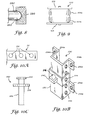
- FIG. 6A is a side view of a fifth wheel-type trailer hitch with multi-directional dampening action according to the present invention.
- FIG. 6B is a rear, partial-cross-sectional view of the trailer hitch of FIG. 6A;
- FIG. 7A is a side, partial-cross-sectional view of another fifth wheel-type trailer hitch with multi-directional dampening action according to the present invention.
- FIG. 7B is an end view of the trailer hitch of FIG. 7A;
- FIG. 8 is a cross-sectional view of a slide block usable with the trailer hitch of FIG. 7A;
- FIG. 9 is a side view of a air spring assembly usable with the invention, wherein a pair of individual air springs are configured to work in series with each other;
- FIGS. 10A-H illustrate adapters for interfacing a trailer hitch according to the invention to a variety of trailers and tow vehicles.
- a receiver-type trailer hitch 10 (henceforth, “receiver hitch 10 ” or “trailer hitch 10 ”) includes a first support member 12 and a second support member 14 with at least one air spring 16 connected therebetween.
- Devices such as air spring 16 are also referred to as “air bags”; these types of devices are occasionally—but improperly—referred to as “air shock absorbers,” “pneumatic shock absorbers,” “air springs,” or the like.
- First support member 12 in this embodiment is a “fixed” support or frame with a frame 18 and a generally flat, horizontal mounting plate 20 having at least one throughhole 21 for attaching the frame to air spring 16 by any suitable type of fastener. Additional throughholes (such as throughhole or throughholes 22 ) may be used to attach first support member 12 to a tow vehicle by means of a bolt, pin, or other suitable fastener or fasteners. Alternatively, a hitch bar or towbar 24 may be used to attach first support member 12 to a receiver hitch or other suitable structure mounted to the tow vehicle.
- At least one generally vertical track 26 is welded to plate 20 generally as shown, substantially perpendicular to the plate.
- a pair of reinforcing gussets may be welded to the tracks and plate 20 for added structural support (a gusset 28 is shown).
- Gussets 28 if present, provide additional structural support that helps prevent or minimize twisting of track 26 under extreme towing conditions; it will be understood that additional gussets and other reinforcements may be provided at other potential stress points of receiver hitch 10 .
- Track 26 preferably encloses the slide blocks (to be described below) generally as shown.
- a pair of wear strips 30 a , 30 b may be attached to the interior walls of track 26 , to reduce wear and the effects of frictional forces during use of receiver hitch 10 .
- Wear strips 30 a , 30 b which may be replaceable, may cover all or part of the interior surfaces of track 26 .
- the interior surfaces of the tracks may be coated with a low-friction, spray-on coating.
- Second support member 14 is a “floating” support or carriage with a generally flat, vertical mounting plate 40 .
- a slide block assembly with at least one pair of spaced-apart, substantially parallel slide blocks such as slide blocks 42 a , 42 b is attached to plate 40 , configured and positioned so that the slide blocks slide freely in track 26 when receiver hitch 10 is fully assembled.
- Slide blocks 42 a , 42 b may be attached to a mounting bar 44 which is welded, bolted, or otherwise attached to plate 40 .
- suitably configured slide blocks 42 a , 42 b may be attached directly to plate 40 .
- a trailer is connected to plate 40 by any suitable devices, including bolts, weight distribution bars, balls, and adapters according to the present invention (to be described further below).
- Slide blocks 42 a , 42 b and wear strips 30 a , 30 b are made of any suitable hard, durable, low-friction material, including a plastic such as ACETAL, NYLATRON, NYLON, TEFLON, or other suitable materials.
- slide blocks 42 a , 42 b and wear strips 30 a , 30 b may be made of suitable laminate or composite materials.
- Mounting bar 44 may be integrally formed with slide blocks 42 a , 42 b , respectively, or made of any hard, durable material (including metal, composite materials, or engineering plastics).
- slide blocks 42 a , 42 b are configured to slide freely in track 26 .
- Slide blocks 42 a , 42 b may be configured so as to have some “give” when receiver hitch 10 is fully assembled. That is, slide blocks 42 a , 42 b may exhibit a modest degree of back-and-forth, side-to-side movement within track 26 that provides a measure of cushioning and flexibility during use to optimize the dampening action of receiver hitch 10 .
- Slide blocks 42 a , 42 b may have generally rectangular cross-sections as shown, but other cross-sectional shapes may also be useful (with an appropriately-shaped track 26 ). For example, track 26 may have a round or oval cross-section.
- two or more spaced-apart slide block assemblies may be provided, each with a pair of slide blocks 42 a , 42 b , each pair of slide blocks being slidable within its corresponding track 26 .
- a frame 48 with an outwardly-extending top plate 50 is attached to plate 40 by welding or other suitable technique.
- Plate 50 which is generally perpendicular to plate 40 , has a throughhole 52 for attaching air spring 16 .
- Plate 50 also acts as a stop to prevent the slide block assembly with slide blocks 42 a , 42 b from moving past the lower end of the track 26 when trailer hitch 10 is assembled.
- the bottom portion of frame 48 acts as a stop to limit the upward movement of slide blocks 42 a , 42 b .
- the top and bottom ends of track 26 may simply be closed.
- air spring 16 may be attached to first support member 12 .
- Air spring 16 has upper and lower mounting lugs which are dimensioned to fit through holes 52 , 21 . Air spring 16 is attached to plates 50 and 20 by inserting the lugs into holes 21 , 52 , and securing the lugs thereto by suitably-sized nuts. Washers or lock washers may be added if desired (for clarity, nuts, bolts, washers, and so forth are not shown in FIG. 2 ). As noted above, air spring 16 is preferably any convenient type of pneumatic (i.e., air or other gas) air spring, preferably a variable-pressure device wherein the pressure may be adjusted through a valve (not shown). Hydraulic or mechanical shock absorbers may be useful for some applications.
- pneumatic i.e., air or other gas
- a spherical rod-end assembly or tie rod assembly 60 is attached between first support member 12 and second support member 14 .
- Rod-end assembly 60 includes at least one pair 62 a , 62 b of rod ends connected between first and second support members 12 , 14 .
- Rod ends 62 a , 62 b are attached by connectors 66 mounted in throughholes 70 a , 70 b of first support member 12 and throughholes 72 a , 72 b of second support member 14 .
- connectors 66 may be any suitable types of connectors that permit rotation or swiveling of each end of rod ends 62 a , 62 b , 64 a , 64 b with respect to first support member 12 and second support member 14 , respectively.
- Bump stops such as 58 a , 58 b may be attached to one or both of plates 20 , 50 to cushion first and second support members 12 , 14 against slamming. Bump stops 58 b may alternatively be attached to stop 48 . If present, bump stops 58 a , 58 b are made of a somewhat resilient, somewhat compressible material such as hard rubber or plastic. Preferably, two pairs of bump stops 58 a , 58 b are included, one pair on either side of air spring 16 (for clarity, only one pair is shown in FIG. 2 ).
- receiver hitch 10 is connected between vehicle V and trailer T as indicated schematically in FIG. 3 .
- Plate 40 may include a plurality of pairs 78 a , 78 b of spaced-apart throughholes. If present, throughholes 78 a , 78 b permit the user to select the optimum pair for attachment to the trailer, thereby allowing the user to optimize the relative heights of the trailer and the vehicle.
- Air spring 16 is inflated to the selected operating pressure through a valve (not shown), thus, the pressure can readily be adjusted for different loads and towing conditions.
- the optimum pressure depends on the anticipated load, the specifications of vehicle V and trailer T, and road conditions, and is best determined by a modest amount of experimentation and observation for each combination of vehicle, trailer, and load.
- Air spring 16 is attached to first support member 12 through hole 21 , and secured by a nut 23 on a first end 84 .
- Slide blocks 42 a , 42 b are inserted into track 26 , and air spring 16 is attached to second support member 14 by a nut 56 on a second end 84 .
- Rod ends 62 a , 62 b and 64 a , 64 b are connected between first and second support members 12 , 14 by connectors 66 .
- Safety chains, sway bars, or other suitable devices may be used on first support member 12 and/or second support member 14 in order to maintain the attachment between the tow vehicle and the trailer in case of separation of the support members.
- the safety chains may be operated by spring pins, removable latch pins, or other suitable devices.
- Weight distribution bars that transfer some of the weight of receiver hitch 10 forward to the front axle of vehicle V may also be installed, particularly if the rear of vehicle V is low due to tongue weight (in some locations, the use of weight distribution bars, safety chains, and like devices may be required).
- first support 12 and second support 14 move with respect to each other as the slide block assembly with slide blocks 42 a , 42 b slides in track 26 (FIG. 3 ).
- Vertical movement of the trailer is represented by arrows A; corresponding generally vertical movement of support members 12 and 14 with respect to each other is represented by arrow C.
- Air spring 16 together with slide blocks 42 a , 42 b moving in track 26 and rods 62 a , 62 b and 64 a , 64 b form a directional dampening system that mechanically isolates the vehicle and the trailer from each other, thereby reducing transmission of up-and-down, side-to-side movement between them.
- vehicle V and trailer T act substantially independently of each other. Transmission of movement between the vehicle and the trailer is dampened by the action of air spring 16 and the smooth, fluid movement of slide blocks 42 a , 42 b in track 26 .
- Trailer T tends to move up-and-down about its own axis instead of about trailer hitch 10 , so that the resulting bouncing, jerking, swaying, and vibration transferred from the trailer to the vehicle by a typical conventional hitch is reduced or eliminated.
- Trailer T and vehicle V are largely isolated from bumps, potholes, and other adverse road features traversed by the other, resulting in reduced transfer of movement between the trailer and the vehicle, and safer and more comfortable driving.
- receiver hitch 10 may transfer no more than approximately 20% of the movement transferred between vehicle V and trailer T by a conventional lock-down type hitch. This approximately 80% reduction results in better control for the driver, a smoother, safer ride for the driver, passengers, and cargo, and ultimately generates less wear and tear on vehicle V and trailer T.
- Receiver hitch 10 may be manufactured in conformance with any applicable standards, for example, Class 3 and 4 hitches (approximately 800 lb. tongue weight, approximately 8,000 lb. gross trailer weight) and Class 5 hitches (approximately 2000 lb. tongue weight, approximately 20,000 lb. gross trailer weight). Two or more such hitches may be installed side-by-side on a single vehicle for heavier-duty applications. Receiver hitch 10 may also include accessories such as air pressure indicators and ride height indicators.
- first support member 12 may be the floating support (i.e., carriage) and second support member 14 the fixed support (i.e., frame).
- towbar 24 is attached to second support member 14 rather than first support member 12 .
- Support members 12 and 14 operate generally in the same manner as the embodiment of FIGS. 2 and 3.
- Receiver hitch 10 has at least one track 26 and a slide block assembly having slide blocks 42 a , 42 b , but may be manufactured with a plurality of tracks 26 with corresponding pairs of slide blocks 42 a , 42 b if desired.
- Air spring 16 may be a single air spring, a single or double bellows air spring, or a plurality of air springs connected in series or parallel (i.e., operating in conjunction with each other or substantially independently of each other).
- hydraulic or mechanical springs may also be useful for some applications.
- one or more auxiliary shock absorbers may be connected between first and second support members 12 , 14 to provide additional dampening action.
- Track 26 and corresponding slide blocks 42 a , 42 b may assume different forms, as may be convenient for any particular application.
- a slide block assembly 90 (FIG. 4A) has a slide block 42 a attached to a support 44 a , where support 44 a is secured to support member 12 or 14 by welding or by suitable fasteners.
- Another slide block assembly 92 (FIG. 4B) has a pair of slide blocks 42 a , 42 b attached to a support plate 94 , which is attached to support member 12 or 14 .
- slide blocks 42 a , 42 b may be of any suitable shapes, and are configured to slide freely in a corresponding track 26 .
- Slide blocks 42 a , 42 b may have oval, circular, or other cross sections (with correspondingly-shaped tracks 26 a , 26 b ).
- a slide block 42 a usable with the invention may have a curved end 46 for use with a curved track 26 a.
- a gooseneck hitch 100 includes a first support member 12 , a second support member 14 , and an air spring assembly 102 (shown in FIG. 5B) which operates in analogous fashion to above-described air spring 16 .
- Air spring assembly 102 includes two variable-pressure air springs 104 a , 104 b (preferably continuously variable pressure air springs), attached between support members 12 and 14 by nuts or other suitable fasteners. The pressure in air springs 104 a , 104 b is adjustable via a valve assembly 316 . If desired, one or more auxiliary shock absorbers of any suitable type may be connected between first and second support members 12 , 14 of gooseneck hitch 100 to provide additional dampening action.
- Gooseneck hitch 100 includes a slide block assembly 300 with at least one slide block 302 and a generally vertical support 304 which is attached to first support member 12 .
- Slide block 302 is attached to support 304 by screws, nuts, or other suitable fasteners in holes 306 , and is configured with a generally vertical notch or groove 308 .
- a key 310 is attached to the interior surface of a hollow housing 312 by screws or other suitable fasteners 314 .
- Slide block 302 is made of NYOIL or other suitable low-friction material.
- groove 308 is configured for slidably receiving key 310 , thereby helping maintain the relative alignment of first and second support members 12 , 14 when gooseneck hitch 100 is in use.
- gooseneck hitch 100 typically transfers no more than approximately 20% of the movement transferred between a tow vehicle and a trailer by a conventional lock-down type hitch.
- the multi-directional dampening action provided by gooseneck hitch reduces transmission of movement between the vehicle and the trailer, resulting in a smoother, safer ride for the driver and passengers, and reduced wear and tear on the load, the vehicle, and the trailer.
- Gooseneck hitch 100 is made of sturdy, durable materials, in conformance with applicable standards. For example, a gooseneck hitch 100 that can support a pin weight of up to approximately 7,000 lb. can be used with a trailer having a gross weight of approximately 25,000 lb.; heavier-duty hitches can support higher gross weights.
- Gooseneck hitch 100 may include accessories such as air pressure indicators, ride height indicators, safety chains, and other devices familiar to those skilled in the art.
- a fifth wheel-type trailer hitch according to the present invention is shown in FIGS. 6A and 6B.
- a fifth wheel hitch 150 for heavy-duty applications includes first and second support members 12 , 14 (as for above-described gooseneck hitch 100 , conventional components of the hitch are shown schematically but not described in detail).
- a fifth wheel head or anvil (shown schematically as 152 ) is attached to a second support member 14 by any suitable fasteners known in the art.
- Anvil 152 may be any suitable type of anvil used with fifth wheel hitches, preferably the type of anvil that can be adjusted both vertically and horizontally. Anvils made by the Reese, Drawtite, and Binkley companies, as well as others, may be useful.
- First support member 12 includes a mounting plate 164 with and a plurality of mounting tabs 160 of any suitable type.
- First support member 12 may be attached directly to the bed of the tow vehicle, but is preferably bolted to rails which are mounted to the bed in a manner known to those skilled in the art.
- auxiliary shock absorbers may be mounted between first and second support members 12 , 14 to provide additional cushioning and dampening action.
- Second support member 14 in this embodiment includes a spreader bar 156 with upwardly-extending flanges 158 a , 158 b .
- Gussets (such as gussets 28 ) may be added for extra structural support if desired. Additional gussets and other reinforcements may be provided at other potential stress points of fifth wheel hitch 150 .
- An air spring assembly 160 which operates in analogous fashion to above-described air spring 16 , has at least one, and preferably a plurality of pairs of air springs is attached between first and second support members 12 , 14 .
- Air spring assembly 160 may, for example, have four such air springs, one at each of the four corners of fifth wheel hitch 150 .
- assembly 160 may have four pairs of air springs, one pair at each corner of the hitch.
- Air springs 162 a , 162 b are attached between support members 12 and 14 by any suitable types of fasteners (shown schematically as 106 a , 106 b ).
- air springs 162 a , 162 b work “in parallel” or somewhat independently of each other to cushion the tow vehicle from jolts, swaying, and other motion of the trailer.
- a slide block assembly 170 includes a slide block 42 terminating a bar 172 which is operably connected to anvil 152 .
- Slide block 42 is slidably received by a pair of tracks 26 a , 26 b in a support structure 140 .
- the movement of slide block 42 is limited by a stop 174 and mounting plate 164 of first support member 12 .
- Bump stops 58 a , 58 b may be attached to plate 164 to cushion first and second support members 12 , 14 against slamming (the bump stops may alternatively be attached to bar 156 ).
- bump stops 58 a , 58 b are made of a somewhat resilient, somewhat compressible material such as hard rubber or plastic.
- air springs 162 a , 162 b operate substantially independently of each other to provide six-way dampening action that reduces the effects of road conditions and also reduces the transmission of trailer movement to the tow vehicle (or vice versa).
- a fifth wheel-type trailer hitch for lighter-duty applications includes first and second support members 12 , 14 (conventional components of the hitch are shown schematically but not described in detail).
- a fifth wheel head or anvil may be attached to second support member 14 by any suitable fasteners known in the art.
- Anvil 152 may be any suitable type of anvil used with fifth wheel hitches, including but not limited to anvils made by the Reese, Drawtite, and Binkley companies.
- First support member 12 includes a mounting plate 164 with a plurality of mounting tabs 160 of any suitable type.
- First support member 12 may be attached directly to the bed of the tow vehicle, but is preferably bolted to rails which are mounted to the bed in a manner known to those skilled in the art.
- auxiliary shock absorbers such as a shock absorber 182
- shock absorbers 182 may be operably connected between first and second support members 12 , 14 to provide additional cushioning and dampening action.
- shock absorbers 182 connected to mounting brackets 184 , 186 by bolts or other suitable fasteners.
- shock absorbers 182 may be connected directly to bars 156 , 164 .
- Second support member 14 includes a spreader bar 156 with upwardly-extending flanges 158 a , 158 b .
- Gussets (such as gussets 28 ) may be added for extra structural support if desired, generally as shown. Additional gussets and other reinforcements may be provided at other potential stress points of fifth wheel hitch 150 .
- Air spring assembly 160 is operably connected between first and second support members 12 , 14 at each of the four corners of fifth wheel hitch 180 .
- Air spring assembly 160 which operates in analogous fashion to above-described air spring 16 , includes at least one air spring; alternatively, assembly 160 may have a pair of air springs.
- Air springs 162 are attached between support members 12 and 14 by any suitable types of fasteners (shown schematically as 106 ). Like above-described air springs 104 a , 104 b , air springs 162 work “in parallel” or somewhat independently of each other to cushion the tow vehicle from jolts, swaying, and other motion of the trailer.
- a slide block assembly 170 at each of the four corners of fifth wheel hitch 180 includes a pair of slide blocks 42 a , 42 b configured for slidable movement in tracks 26 a , 26 b in a support structure 190 .
- the movement of slide blocks 42 a , 42 b is limited by stops 192 , 194 .
- Bump stops (such as above-described bump stops 58 a , 58 b ) may be attached to plate 164 (or some other convenient position) to help prevent slamming.
- Slide blocks 42 a , 42 b may have square, rectangular, oval, circular, or other cross sections (with correspondingly-shaped tracks 26 a , 26 b ).
- a slide block 280 usable with the invention may have a curved end 284 for use with a curved track 282 (FIG. 8 ).
- slide blocks 42 a , 42 b in tracks 26 a , 26 b helps reduce the transmission of relative movement between the tow vehicle and the trailer.
- air springs 162 operate substantially independently of each other to provide six-way dampening action that reduces the effects of road conditions and also reduces the transmission of trailer movement to the tow vehicle (or vice versa).
- a trailer hitch according to the present invention may transmit no more than approximately 20% of the back-and-forth, up-and-down, side-to-side movement of a trailer to a vehicle (or vice versa) than is transmitted by a conventional lock-down hitch.
- the tow vehicle and the trailer move substantially independently of each other, resulting in a smoother, safer ride for the driver, passengers, and cargo.
- Driver fatigue is postponed due to the more comfortable ride, easier handling, and improved braking of the vehicle-trailer combination, even on rough roads and badly cambered roads and curves. Wear and tear on the vehicle, trailer, and load are reduced.
- the hitch can readily be adjusted for different types and weights of load simply by adjusting the pressure in the air springs. If the air springs lose pressure for any reason, the hitch functions as a conventional lock-down or solid hitch until the user can effect any needed maintenance or repairs (bump stops 58 a , 58 b , where present, help prevent slamming of first and second support members 12 , 14 into each other).
- hitch components are preferably made of sturdy, durable materials, including but not limited to stainless steel, steel, aluminum, and iron.
- Metal components of hitches 10 , 100 , 150 may be machined of standard stock and welded or otherwise fastened together; alternatively, some or all of these components may be cast by suitable techniques known in the art of metal-working.
- tracks 26 may be made of heavy-duty stainless steel.
- Slide blocks 42 a , 42 b in their various embodiments are preferably made of low-friction plastics such as NYLATRON, NYOIL, ACETAL, TEFLON and the like (however, laminate and composite materials may also be useful). Heavy-duty welds, gussets (such as 28 a , 28 b ), and other reinforcements may be included as convenient.
- low-friction plastics such as NYLATRON, NYOIL, ACETAL, TEFLON and the like (however, laminate and composite materials may also be useful).
- Heavy-duty welds, gussets (such as 28 a , 28 b ), and other reinforcements may be included as convenient.
- retainers such as safety chains, weight distribution bars, sway bars, belts, and the like may connect first and second support members 12 and 14 in any of the above-described embodiments of the invention. If present, the retainers keep the vehicle and the trailer from separating if first and second support members 12 and 14 accidentally separate while the hitch is in use. All embodiments of the invention may include bump stops (such as stops 58 a , 58 b ) at suitable locations to help cushion against slamming.
- FIG. 9 The Figures generally show the use of single bellows type air springs.
- double bellows air spring or an air spring assembly 200 (FIG. 9) may be used if desired.
- Assembly 200 has a plurality of air springs, for example, a pair of air springs 202 a , 202 b , wherein the individual air springs 202 a , 202 b work in tandem or “in series.” Indeed, three or more such air springs may be useful for some applications.
- a problem for many users (and potential users) of presently-available trailer hitches is that of attaching their selected trailer hitch to an available vehicle.
- Many hitches simply cannot be used with more than a few different vehicles: for example, a receiver type hitch designed for use with many Ford and Chevrolet pick-up trucks may not be usable with a minivan (even one made by the same manufacturer).
- a customer who wants a trailer hitch for his or her vehicle has a limited selection to choose from, and that selection may not include the best type of hitch for that customer's intended towing applications.
- the present invention includes adapters that can interface hitches 10 , 100 , 150 , 180 between most trailers (open and closed trailers, recreational vehicles or RVs, campers, horse and other animal trailers, etc.) and virtually any type or brand of motor vehicle (passenger cars, minivans, vans, pickup trucks, tractor trailers, etc.).
- a simple adapter may be formed by a plurality of spaced throughholes 210 in towbar 24 (FIG. 10 A). Throughholes 210 permit attachment of towbar 24 to vehicles of different sizes and configurations, thereby adding to the versatility of hitches equipped with such a towbar. The optimum throughhole for any vehicle/trailer combination is selected based on the vehicle, the load capacity of the trailer, and the particular hitch used.
- Adapter 230 consists of a generally vertical bar 232 with a pair of projections 234 a , 234 b at its upper end. Projections 234 a , 234 b have throughholes 236 a , 236 b whereby adapter 230 can be attached to a selected pair of throughholes 220 a , 220 b of plate 40 by nuts and bolts (or other suitable fasteners). Bar 232 has a spaced series of throughholes 238 for attachment of a mounting bracket 240 .
- a mounting bracket 240 with a throughhole 244 , is attached to a selected throughhole 238 of bar 232 by nuts and bolts or other suitable fasteners; a ball hitch 246 is attached as shown.
- Adapter 230 used alone or in conjunction with plate 40 as shown in FIG. 2, allows the user to quickly and easily adjust the relative heights of the tow vehicle and the trailer simply by selecting the optimum combination of throughhole 238 (for mounting bracket 240 to adapter 230 ) and throughholes 220 a , 220 b (for mounting adapter 230 to plate 40 ).
- Adapter 250 allows the user to use fifth wheel hitches 150 , 180 with a standard gooseneck mount.
- Adapter 250 has a generally cylindrical base 252 which is attachable to a gooseneck mount (not shown), with a circumferential flange or plate 254 and a king pin 256 .
- a spreader bar assembly 260 for use with fifth wheel hitches 150 , 180 is shown in FIG. 10 D.
- Assembly 260 has a pair of spreader bars 158 a , 158 b connected by a bar 156 ; bars 158 a , 158 b have a plurality of throughholes 182 a , 182 b .
- the combination of bar 156 and throughholes 182 a , 182 b allows the user to adjust the horizontal and vertical positions of assembly 180 in order to interface anvil 152 to trailer hitch 180 .
- a quick change ball mount 190 (FIG. 10E) includes an approximately U-shaped section 192 welded or otherwise affixed to an L-shaped plate 194 with throughholes 196 , 198 formed therein.
- Ball mount 190 is bolted to any suitable base at throughholes 200 a , 200 b ; a ball-type hitch is attached at throughhole 196 and a weight distribution component (not shown) at throughhole 198 .
- Ball mount 190 is reversible so that throughhole 198 can be positioned at either the left or the right of section 192 .
- FIGS. 10F-H front, side, and top views, respectively.
- Adapter 210 includes a plate 212 , a bar 214 , and a plurality of throughholes 216 , 218 formed as shown.
- a tongue 220 projects outwards from bar 218 (FIG. 8 I), with a throughhole 222 for attachment of a ball-type hitch.
- adapter 210 can be inverted for use.
- Plate 272 can be attached at any selected pair of throughholes 220 a , 220 b of plate 40 .
- slide blocks 42 a , 42 b and tracks 26 a , 26 b may assume a variety of configurations without departing from the spirit of the present invention.
- Slide block 42 a as shown in FIGS. 3, 5 A and 5 B may be used with any of hitches 10 , 100 , 150 , 180 .
- either the “fixed” or “floating” support of support members 12 , 14 may carry slide blocks 42 a , 42 b with the other support carrying tracks 26 a , 26 b.
Abstract
Description
Claims (4)
Priority Applications (1)
| Application Number | Priority Date | Filing Date | Title |
|---|---|---|---|
| US10/281,650 US6746037B1 (en) | 2000-12-20 | 2002-10-28 | Trailer hitch with multi-directional dampening system and spherical rod-end assembly |
Applications Claiming Priority (3)
| Application Number | Priority Date | Filing Date | Title |
|---|---|---|---|
| US25718300P | 2000-12-20 | 2000-12-20 | |
| US2506601A | 2001-12-19 | 2001-12-19 | |
| US10/281,650 US6746037B1 (en) | 2000-12-20 | 2002-10-28 | Trailer hitch with multi-directional dampening system and spherical rod-end assembly |
Related Parent Applications (1)
| Application Number | Title | Priority Date | Filing Date |
|---|---|---|---|
| US2506601A Continuation-In-Part | 2000-12-20 | 2001-12-19 |
Publications (1)
| Publication Number | Publication Date |
|---|---|
| US6746037B1 true US6746037B1 (en) | 2004-06-08 |
Family
ID=32328508
Family Applications (1)
| Application Number | Title | Priority Date | Filing Date |
|---|---|---|---|
| US10/281,650 Expired - Fee Related US6746037B1 (en) | 2000-12-20 | 2002-10-28 | Trailer hitch with multi-directional dampening system and spherical rod-end assembly |
Country Status (1)
| Country | Link |
|---|---|
| US (1) | US6746037B1 (en) |
Cited By (69)
| Publication number | Priority date | Publication date | Assignee | Title |
|---|---|---|---|---|
| US20040169348A1 (en) * | 2002-10-01 | 2004-09-02 | Elmer Winckler | Towing hitch assembly |
| US20060097483A1 (en) * | 2004-11-10 | 2006-05-11 | White Gary A | Force absorbing towing hitch |
| US20060163840A1 (en) * | 2005-01-24 | 2006-07-27 | Schwalbe Dennis A | Air supported trailer hitch |
| US7108272B1 (en) * | 2004-03-26 | 2006-09-19 | Gurtler Wendell A | Trailer hitch cushioning device and method for using same |
| US20060232042A1 (en) * | 2005-04-13 | 2006-10-19 | Graber John D | Trailer damping apparatus and trailer utilizing same |
| US7273114B1 (en) | 2005-12-02 | 2007-09-25 | Jacob Sidney Rand | Elimination of jack-knifing of the tractor-trailers |
| US20070284852A1 (en) * | 2006-06-13 | 2007-12-13 | Mater Robert F | Pin box assembly for trailer |
| US20080029996A1 (en) * | 2006-06-13 | 2008-02-07 | Mater Robert F Jr | Extension coupling for interconnecting trailer and tow hitch |
| US7380810B1 (en) | 2005-04-21 | 2008-06-03 | Air Hitch Technology, Llc | Vehicle hitch with multi-directional damping |
| US20080164678A1 (en) * | 2007-01-05 | 2008-07-10 | Gary White | Air ride hitch |
| US7416378B1 (en) * | 2006-09-12 | 2008-08-26 | Adams Bill J | Load lift control system |
| US20080224443A1 (en) * | 2007-03-16 | 2008-09-18 | James William Kovach | Fifth wheel hitch assembly |
| US20080238066A1 (en) * | 2007-03-09 | 2008-10-02 | Muirbrook Carl T | Methods and devices for outdoor cooking |
| US20090072518A1 (en) * | 2002-10-16 | 2009-03-19 | Roll Michael J | Trailer coupler assembly |
| US20090134601A1 (en) * | 2007-10-25 | 2009-05-28 | Jeff Wilkens | Vehicle hitch with multi-directional damping |
| US7552937B1 (en) | 2006-06-16 | 2009-06-30 | Shelton Taylor | Shock-absorbing adapter for connecting fifth wheel or gooseneck trailer to towing vehicle |
| US20090303512A1 (en) * | 2008-06-04 | 2009-12-10 | Xerox Corporation | Automated imposition for print jobs with exception pages |
| US20100133780A1 (en) * | 2007-04-30 | 2010-06-03 | Silver Eagle Manufacturing Co. | Roll-stabilizing fifth wheel apparatus |
| US7753391B1 (en) | 2008-04-17 | 2010-07-13 | Automatic Equipment Manufacturing Company | Torsionally-biased, shock-absorbing fifth wheel hitch |
| US20100322580A1 (en) * | 2009-06-22 | 2010-12-23 | Beamon Hubert B | Fiber Optic Cable Parking Device |
| US20100322579A1 (en) * | 2009-06-19 | 2010-12-23 | Cooke Terry L | High-density fiber optic modules and module housings and related equipment |
| US20110188220A1 (en) * | 2010-02-04 | 2011-08-04 | Blackwell Jr Chois A | Communications equipment housings, assemblies, and related alignment features and methods |
| US20120307308A1 (en) * | 2007-03-05 | 2012-12-06 | Morales Javier A | Automated imposition for print jobs with exception pages |
| USD686953S1 (en) | 2012-02-21 | 2013-07-30 | Cequent Performance Products, Inc. | Gooseneck coupler head |
| RU2496290C2 (en) * | 2008-07-24 | 2013-10-27 | Дир Энд Компани | Traction type and coupling equipment for automatic performance of connection of towing hitch and hydraulic quick-acting hitch mechanisms between trailer of nurse tank and agricultural tools of machine for application of nh3 |
| US8625950B2 (en) | 2009-12-18 | 2014-01-07 | Corning Cable Systems Llc | Rotary locking apparatus for fiber optic equipment trays and related methods |
| US8660397B2 (en) | 2010-04-30 | 2014-02-25 | Corning Cable Systems Llc | Multi-layer module |
| US8662760B2 (en) | 2010-10-29 | 2014-03-04 | Corning Cable Systems Llc | Fiber optic connector employing optical fiber guide member |
| US8699838B2 (en) | 2009-05-14 | 2014-04-15 | Ccs Technology, Inc. | Fiber optic furcation module |
| US8705926B2 (en) | 2010-04-30 | 2014-04-22 | Corning Optical Communications LLC | Fiber optic housings having a removable top, and related components and methods |
| US8718436B2 (en) | 2010-08-30 | 2014-05-06 | Corning Cable Systems Llc | Methods, apparatuses for providing secure fiber optic connections |
| US8783705B2 (en) | 2011-02-21 | 2014-07-22 | Cequent Performance Products, Inc. | Gooseneck coupler with slideable style locking members |
| US8879881B2 (en) | 2010-04-30 | 2014-11-04 | Corning Cable Systems Llc | Rotatable routing guide and assembly |
| US8913866B2 (en) | 2010-03-26 | 2014-12-16 | Corning Cable Systems Llc | Movable adapter panel |
| US8953924B2 (en) | 2011-09-02 | 2015-02-10 | Corning Cable Systems Llc | Removable strain relief brackets for securing fiber optic cables and/or optical fibers to fiber optic equipment, and related assemblies and methods |
| US8965168B2 (en) | 2010-04-30 | 2015-02-24 | Corning Cable Systems Llc | Fiber management devices for fiber optic housings, and related components and methods |
| US8985862B2 (en) | 2013-02-28 | 2015-03-24 | Corning Cable Systems Llc | High-density multi-fiber adapter housings |
| US8989547B2 (en) | 2011-06-30 | 2015-03-24 | Corning Cable Systems Llc | Fiber optic equipment assemblies employing non-U-width-sized housings and related methods |
| US8995812B2 (en) | 2012-10-26 | 2015-03-31 | Ccs Technology, Inc. | Fiber optic management unit and fiber optic distribution device |
| US9004510B2 (en) * | 2007-03-16 | 2015-04-14 | Polaris Industries Inc. | Vehicle |
| US9008485B2 (en) | 2011-05-09 | 2015-04-14 | Corning Cable Systems Llc | Attachment mechanisms employed to attach a rear housing section to a fiber optic housing, and related assemblies and methods |
| US9020320B2 (en) | 2008-08-29 | 2015-04-28 | Corning Cable Systems Llc | High density and bandwidth fiber optic apparatuses and related equipment and methods |
| US9022814B2 (en) | 2010-04-16 | 2015-05-05 | Ccs Technology, Inc. | Sealing and strain relief device for data cables |
| US9038832B2 (en) | 2011-11-30 | 2015-05-26 | Corning Cable Systems Llc | Adapter panel support assembly |
| US9042702B2 (en) | 2012-09-18 | 2015-05-26 | Corning Cable Systems Llc | Platforms and systems for fiber optic cable attachment |
| US9059578B2 (en) | 2009-02-24 | 2015-06-16 | Ccs Technology, Inc. | Holding device for a cable or an assembly for use with a cable |
| US9075217B2 (en) | 2010-04-30 | 2015-07-07 | Corning Cable Systems Llc | Apparatuses and related components and methods for expanding capacity of fiber optic housings |
| US9116324B2 (en) | 2010-10-29 | 2015-08-25 | Corning Cable Systems Llc | Stacked fiber optic modules and fiber optic equipment configured to support stacked fiber optic modules |
| US9213161B2 (en) | 2010-11-05 | 2015-12-15 | Corning Cable Systems Llc | Fiber body holder and strain relief device |
| US9250409B2 (en) | 2012-07-02 | 2016-02-02 | Corning Cable Systems Llc | Fiber-optic-module trays and drawers for fiber-optic equipment |
| US9279951B2 (en) | 2010-10-27 | 2016-03-08 | Corning Cable Systems Llc | Fiber optic module for limited space applications having a partially sealed module sub-assembly |
| US9370978B1 (en) * | 2015-06-14 | 2016-06-21 | Robert C. Sagen | Hitch adapter system with damping effect |
| US9519118B2 (en) | 2010-04-30 | 2016-12-13 | Corning Optical Communications LLC | Removable fiber management sections for fiber optic housings, and related components and methods |
| AU2013221947B2 (en) * | 2012-08-28 | 2017-04-13 | Oz Glide Pty Ltd | Trailer hitch shock dampening system |
| US9632270B2 (en) | 2010-04-30 | 2017-04-25 | Corning Optical Communications LLC | Fiber optic housings configured for tool-less assembly, and related components and methods |
| US9645317B2 (en) | 2011-02-02 | 2017-05-09 | Corning Optical Communications LLC | Optical backplane extension modules, and related assemblies suitable for establishing optical connections to information processing modules disposed in equipment racks |
| US9720195B2 (en) | 2010-04-30 | 2017-08-01 | Corning Optical Communications LLC | Apparatuses and related components and methods for attachment and release of fiber optic housings to and from an equipment rack |
| CN107380195A (en) * | 2017-08-02 | 2017-11-24 | 苏州中车轨道交通车辆有限公司 | Flexibility height adjustable transition car coupler used for rail vehicle |
| US10094996B2 (en) | 2008-08-29 | 2018-10-09 | Corning Optical Communications, Llc | Independently translatable modules and fiber optic equipment trays in fiber optic equipment |
| US20180310458A1 (en) * | 2016-05-19 | 2018-11-01 | Deere & Company | Work vehicle suspension hitch |
| US10238034B2 (en) * | 2016-05-30 | 2019-03-26 | Multione Srl | Coupling device for power-operated machines |
| US11001110B2 (en) | 2019-04-10 | 2021-05-11 | Colton Farquer | Vibration and load trailer dampening system |
| US11186314B2 (en) * | 2018-08-22 | 2021-11-30 | Plasan Sasa Ltd. | Articulated vehicle assembly and articulation system for use therein |
| US20220097868A1 (en) * | 2020-09-29 | 2022-03-31 | Safran Landing Systems Canada Inc. | Remote aircraft towing interface |
| US11294136B2 (en) | 2008-08-29 | 2022-04-05 | Corning Optical Communications LLC | High density and bandwidth fiber optic apparatuses and related equipment and methods |
| DE102022002613A1 (en) | 2021-07-19 | 2023-01-19 | Mercedes-Benz Group AG | Trailer hitch system for vehicles |
| US11648970B2 (en) | 2021-03-11 | 2023-05-16 | Bryce Gibson | Convertible, all-terrain gear cart |
| DE102023003016A1 (en) | 2022-08-09 | 2024-02-15 | Mercedes-Benz Group AG | Trailer coupling position for different body designs |
| US11945529B2 (en) | 2021-05-10 | 2024-04-02 | Plasan Sasa Ltd. | Dual use trailer vehicle |
Citations (35)
| Publication number | Priority date | Publication date | Assignee | Title |
|---|---|---|---|---|
| US2150269A (en) | 1937-09-03 | 1939-03-14 | Gerald H Dreisbach | Floating drawbar guide for tractors |
| US2733931A (en) | 1956-02-07 | Fifth wheel suspension for trailers and the like | ||
| US2968496A (en) | 1958-10-22 | 1961-01-17 | Gouirand Rene | Pneumatic suspension for tractors |
| US3137515A (en) | 1962-04-16 | 1964-06-16 | Neway Equipment Co | Fifth wheel structure |
| US3203723A (en) | 1962-07-10 | 1965-08-31 | Montenare Anthony | Pneumatically cushioned bumper |
| US3208770A (en) * | 1962-04-06 | 1965-09-28 | Anthony P Freitas | Fifth wheel pneumatic suspension system |
| US3227470A (en) | 1963-07-18 | 1966-01-04 | Funk Richard Paul | Tractor-trailer load transferring device |
| US3269751A (en) | 1964-02-11 | 1966-08-30 | Whattoff Motor Co | Adjustable hitch |
| US3380758A (en) * | 1966-03-02 | 1968-04-30 | Ole Granning Trailer Service I | Air lift fifth wheel control system |
| US3400949A (en) | 1966-07-19 | 1968-09-10 | Ray E. Kendall | Trailer hitch with vertically adjustable ball |
| US3426377A (en) | 1967-05-03 | 1969-02-11 | Loomis Machine Co | Dockboard |
| US3708183A (en) | 1970-12-11 | 1973-01-02 | David Dale Lloyd | Trailer hitch |
| US3865406A (en) | 1974-05-31 | 1975-02-11 | Truck Specialist Inc | Quick change hitch for trailer or mobile homes |
| US4057265A (en) | 1976-11-24 | 1977-11-08 | Grace Bud W | Towing apparatus |
| US4137587A (en) | 1975-10-17 | 1979-02-06 | Rosengren Knut T L | Dockboard apparatus |
| US4148498A (en) | 1977-10-17 | 1979-04-10 | Taylor Jr Thomas A | Trailer hitch |
| US4153270A (en) | 1978-06-09 | 1979-05-08 | Brockmiller Robert L | Sliding hitch-ball holder and guide rack assembly |
| US4215876A (en) | 1978-09-27 | 1980-08-05 | Jacks Donald E | Trailer hitch |
| US4373847A (en) | 1981-05-04 | 1983-02-15 | Rite-Hite Corporation | Releasable locking device |
| US4564209A (en) | 1983-09-22 | 1986-01-14 | Kingsley Bertis N | Trailer hitch assembly |
| US4580806A (en) * | 1984-04-20 | 1986-04-08 | Tartan Transportation Systems, Inc. | Pneumatic suspension system |
| US4632371A (en) | 1984-03-21 | 1986-12-30 | Stabilus Gmbh | Gas spring of variable spring force |
| US5209316A (en) | 1991-10-16 | 1993-05-11 | Applied Power Inc. | Truck cab suspension unit |
| US5226675A (en) | 1991-05-31 | 1993-07-13 | Trw Inc. | Fifth wheel suspension |
| US5413366A (en) | 1993-06-07 | 1995-05-09 | Gibbons; Eldon L. | Vertically adjustable trailer hitch |
| US5427471A (en) | 1994-02-03 | 1995-06-27 | Godbersen; Byron I. | Dock mounted boat hoist |
| US5503423A (en) | 1994-06-14 | 1996-04-02 | Tracker Marine, L.P. | Swing away hitch assembly for a trailer and method of manufacturing same |
| US5639106A (en) | 1995-05-18 | 1997-06-17 | Vitale; Frank | Tractor-trailer fifth wheel air suspension assembly |
| US5695204A (en) | 1996-01-05 | 1997-12-09 | Ford; Billy Clyde | Hitch adapter with protective device |
| US5704086A (en) | 1996-01-02 | 1998-01-06 | Fmc Corporation | Passenger boarding bridge |
| US5823560A (en) | 1997-06-02 | 1998-10-20 | Van Vleet; Robert D. | Two way cushioning trailer hitch |
| US5836603A (en) | 1997-04-03 | 1998-11-17 | Logan; Jeff | Shock absorbing trailer hitch |
| US6116631A (en) | 1998-11-16 | 2000-09-12 | Easy Rider Incorporated | Shock absorbing trailer hitch assembly |
| US6170852B1 (en) | 1999-03-01 | 2001-01-09 | Alan M. Kimbrough | Trailer hitch assembly |
| US6170849B1 (en) * | 1998-12-29 | 2001-01-09 | Mccall Eugene L. | McCall air ride 5th wheel hitch system |
-
2002
- 2002-10-28 US US10/281,650 patent/US6746037B1/en not_active Expired - Fee Related
Patent Citations (35)
| Publication number | Priority date | Publication date | Assignee | Title |
|---|---|---|---|---|
| US2733931A (en) | 1956-02-07 | Fifth wheel suspension for trailers and the like | ||
| US2150269A (en) | 1937-09-03 | 1939-03-14 | Gerald H Dreisbach | Floating drawbar guide for tractors |
| US2968496A (en) | 1958-10-22 | 1961-01-17 | Gouirand Rene | Pneumatic suspension for tractors |
| US3208770A (en) * | 1962-04-06 | 1965-09-28 | Anthony P Freitas | Fifth wheel pneumatic suspension system |
| US3137515A (en) | 1962-04-16 | 1964-06-16 | Neway Equipment Co | Fifth wheel structure |
| US3203723A (en) | 1962-07-10 | 1965-08-31 | Montenare Anthony | Pneumatically cushioned bumper |
| US3227470A (en) | 1963-07-18 | 1966-01-04 | Funk Richard Paul | Tractor-trailer load transferring device |
| US3269751A (en) | 1964-02-11 | 1966-08-30 | Whattoff Motor Co | Adjustable hitch |
| US3380758A (en) * | 1966-03-02 | 1968-04-30 | Ole Granning Trailer Service I | Air lift fifth wheel control system |
| US3400949A (en) | 1966-07-19 | 1968-09-10 | Ray E. Kendall | Trailer hitch with vertically adjustable ball |
| US3426377A (en) | 1967-05-03 | 1969-02-11 | Loomis Machine Co | Dockboard |
| US3708183A (en) | 1970-12-11 | 1973-01-02 | David Dale Lloyd | Trailer hitch |
| US3865406A (en) | 1974-05-31 | 1975-02-11 | Truck Specialist Inc | Quick change hitch for trailer or mobile homes |
| US4137587A (en) | 1975-10-17 | 1979-02-06 | Rosengren Knut T L | Dockboard apparatus |
| US4057265A (en) | 1976-11-24 | 1977-11-08 | Grace Bud W | Towing apparatus |
| US4148498A (en) | 1977-10-17 | 1979-04-10 | Taylor Jr Thomas A | Trailer hitch |
| US4153270A (en) | 1978-06-09 | 1979-05-08 | Brockmiller Robert L | Sliding hitch-ball holder and guide rack assembly |
| US4215876A (en) | 1978-09-27 | 1980-08-05 | Jacks Donald E | Trailer hitch |
| US4373847A (en) | 1981-05-04 | 1983-02-15 | Rite-Hite Corporation | Releasable locking device |
| US4564209A (en) | 1983-09-22 | 1986-01-14 | Kingsley Bertis N | Trailer hitch assembly |
| US4632371A (en) | 1984-03-21 | 1986-12-30 | Stabilus Gmbh | Gas spring of variable spring force |
| US4580806A (en) * | 1984-04-20 | 1986-04-08 | Tartan Transportation Systems, Inc. | Pneumatic suspension system |
| US5226675A (en) | 1991-05-31 | 1993-07-13 | Trw Inc. | Fifth wheel suspension |
| US5209316A (en) | 1991-10-16 | 1993-05-11 | Applied Power Inc. | Truck cab suspension unit |
| US5413366A (en) | 1993-06-07 | 1995-05-09 | Gibbons; Eldon L. | Vertically adjustable trailer hitch |
| US5427471A (en) | 1994-02-03 | 1995-06-27 | Godbersen; Byron I. | Dock mounted boat hoist |
| US5503423A (en) | 1994-06-14 | 1996-04-02 | Tracker Marine, L.P. | Swing away hitch assembly for a trailer and method of manufacturing same |
| US5639106A (en) | 1995-05-18 | 1997-06-17 | Vitale; Frank | Tractor-trailer fifth wheel air suspension assembly |
| US5704086A (en) | 1996-01-02 | 1998-01-06 | Fmc Corporation | Passenger boarding bridge |
| US5695204A (en) | 1996-01-05 | 1997-12-09 | Ford; Billy Clyde | Hitch adapter with protective device |
| US5836603A (en) | 1997-04-03 | 1998-11-17 | Logan; Jeff | Shock absorbing trailer hitch |
| US5823560A (en) | 1997-06-02 | 1998-10-20 | Van Vleet; Robert D. | Two way cushioning trailer hitch |
| US6116631A (en) | 1998-11-16 | 2000-09-12 | Easy Rider Incorporated | Shock absorbing trailer hitch assembly |
| US6170849B1 (en) * | 1998-12-29 | 2001-01-09 | Mccall Eugene L. | McCall air ride 5th wheel hitch system |
| US6170852B1 (en) | 1999-03-01 | 2001-01-09 | Alan M. Kimbrough | Trailer hitch assembly |
Cited By (111)
| Publication number | Priority date | Publication date | Assignee | Title |
|---|---|---|---|---|
| US7125034B2 (en) * | 2002-10-01 | 2006-10-24 | Elmer Winckler | Towing hitch assembly |
| US20040169348A1 (en) * | 2002-10-01 | 2004-09-02 | Elmer Winckler | Towing hitch assembly |
| US20070052202A1 (en) * | 2002-10-01 | 2007-03-08 | Elmer Winckler | Towing hitch assembly |
| US7669877B2 (en) | 2002-10-16 | 2010-03-02 | Cequent Trailer Products, Inc. | Trailer coupler assembly |
| US20090072518A1 (en) * | 2002-10-16 | 2009-03-19 | Roll Michael J | Trailer coupler assembly |
| US7108272B1 (en) * | 2004-03-26 | 2006-09-19 | Gurtler Wendell A | Trailer hitch cushioning device and method for using same |
| US20060097483A1 (en) * | 2004-11-10 | 2006-05-11 | White Gary A | Force absorbing towing hitch |
| US20060163840A1 (en) * | 2005-01-24 | 2006-07-27 | Schwalbe Dennis A | Air supported trailer hitch |
| US7562892B2 (en) * | 2005-01-24 | 2009-07-21 | Schwalbe Dennis A | Air supported trailer hitch |
| US20060232042A1 (en) * | 2005-04-13 | 2006-10-19 | Graber John D | Trailer damping apparatus and trailer utilizing same |
| US7338063B2 (en) | 2005-04-13 | 2008-03-04 | Graber John D | Trailer damping apparatus and trailer utilizing same |
| US7380810B1 (en) | 2005-04-21 | 2008-06-03 | Air Hitch Technology, Llc | Vehicle hitch with multi-directional damping |
| US7273114B1 (en) | 2005-12-02 | 2007-09-25 | Jacob Sidney Rand | Elimination of jack-knifing of the tractor-trailers |
| US7530591B2 (en) | 2006-06-13 | 2009-05-12 | Cequent Performance Products, Inc. | Pin box assembly for trailer |
| US20070284852A1 (en) * | 2006-06-13 | 2007-12-13 | Mater Robert F | Pin box assembly for trailer |
| US8100427B2 (en) | 2006-06-13 | 2012-01-24 | Cequent Performance Products, Inc. | Pin box assembly for trailer |
| US7997608B2 (en) | 2006-06-13 | 2011-08-16 | Cequent Performance Products, Inc. | Pin box assembly for trailer |
| US7712761B2 (en) | 2006-06-13 | 2010-05-11 | Cequent Performance Products, Inc. | Extension coupling for interconnecting trailer and tow hitch |
| US20100072728A1 (en) * | 2006-06-13 | 2010-03-25 | Cequent Performance Products, Inc. | Pin box assembly for trailer |
| US20080029996A1 (en) * | 2006-06-13 | 2008-02-07 | Mater Robert F Jr | Extension coupling for interconnecting trailer and tow hitch |
| US20080042398A1 (en) * | 2006-06-13 | 2008-02-21 | Mater Robert F Jr | Pin box assembly for trailer |
| US7552937B1 (en) | 2006-06-16 | 2009-06-30 | Shelton Taylor | Shock-absorbing adapter for connecting fifth wheel or gooseneck trailer to towing vehicle |
| US7416378B1 (en) * | 2006-09-12 | 2008-08-26 | Adams Bill J | Load lift control system |
| US20080164678A1 (en) * | 2007-01-05 | 2008-07-10 | Gary White | Air ride hitch |
| US20120307308A1 (en) * | 2007-03-05 | 2012-12-06 | Morales Javier A | Automated imposition for print jobs with exception pages |
| US20080238066A1 (en) * | 2007-03-09 | 2008-10-02 | Muirbrook Carl T | Methods and devices for outdoor cooking |
| US7703793B2 (en) | 2007-03-16 | 2010-04-27 | James William Kovach | Fifth wheel hitch assembly |
| US11254372B2 (en) | 2007-03-16 | 2022-02-22 | Polaris Industries Inc. | Vehicle |
| US10960937B2 (en) | 2007-03-16 | 2021-03-30 | Polaris Industries Inc. | Vehicle |
| US20080224443A1 (en) * | 2007-03-16 | 2008-09-18 | James William Kovach | Fifth wheel hitch assembly |
| US9004510B2 (en) * | 2007-03-16 | 2015-04-14 | Polaris Industries Inc. | Vehicle |
| US20100133780A1 (en) * | 2007-04-30 | 2010-06-03 | Silver Eagle Manufacturing Co. | Roll-stabilizing fifth wheel apparatus |
| US8146939B2 (en) | 2007-04-30 | 2012-04-03 | Silver Eagle Manufacturing Company | Roll-stabilizing fifth wheel apparatus |
| US7810831B2 (en) | 2007-10-25 | 2010-10-12 | Jeff Wilkens | Vehicle hitch with multi-directional damping |
| US20090134601A1 (en) * | 2007-10-25 | 2009-05-28 | Jeff Wilkens | Vehicle hitch with multi-directional damping |
| US7753391B1 (en) | 2008-04-17 | 2010-07-13 | Automatic Equipment Manufacturing Company | Torsionally-biased, shock-absorbing fifth wheel hitch |
| US20090303512A1 (en) * | 2008-06-04 | 2009-12-10 | Xerox Corporation | Automated imposition for print jobs with exception pages |
| RU2496290C2 (en) * | 2008-07-24 | 2013-10-27 | Дир Энд Компани | Traction type and coupling equipment for automatic performance of connection of towing hitch and hydraulic quick-acting hitch mechanisms between trailer of nurse tank and agricultural tools of machine for application of nh3 |
| US10126514B2 (en) | 2008-08-29 | 2018-11-13 | Corning Optical Communications, Llc | Independently translatable modules and fiber optic equipment trays in fiber optic equipment |
| US11294136B2 (en) | 2008-08-29 | 2022-04-05 | Corning Optical Communications LLC | High density and bandwidth fiber optic apparatuses and related equipment and methods |
| US10564378B2 (en) | 2008-08-29 | 2020-02-18 | Corning Optical Communications LLC | High density and bandwidth fiber optic apparatuses and related equipment and methods |
| US10444456B2 (en) | 2008-08-29 | 2019-10-15 | Corning Optical Communications LLC | High density and bandwidth fiber optic apparatuses and related equipment and methods |
| US10120153B2 (en) | 2008-08-29 | 2018-11-06 | Corning Optical Communications, Llc | Independently translatable modules and fiber optic equipment trays in fiber optic equipment |
| US10422971B2 (en) | 2008-08-29 | 2019-09-24 | Corning Optical Communicatinos LLC | High density and bandwidth fiber optic apparatuses and related equipment and methods |
| US10416405B2 (en) | 2008-08-29 | 2019-09-17 | Corning Optical Communications LLC | Independently translatable modules and fiber optic equipment trays in fiber optic equipment |
| US10606014B2 (en) | 2008-08-29 | 2020-03-31 | Corning Optical Communications LLC | Independently translatable modules and fiber optic equipment trays in fiber optic equipment |
| US10094996B2 (en) | 2008-08-29 | 2018-10-09 | Corning Optical Communications, Llc | Independently translatable modules and fiber optic equipment trays in fiber optic equipment |
| US11754796B2 (en) | 2008-08-29 | 2023-09-12 | Corning Optical Communications LLC | Independently translatable modules and fiber optic equipment trays in fiber optic equipment |
| US11609396B2 (en) | 2008-08-29 | 2023-03-21 | Corning Optical Communications LLC | High density and bandwidth fiber optic apparatuses and related equipment and methods |
| US10222570B2 (en) | 2008-08-29 | 2019-03-05 | Corning Optical Communications LLC | Independently translatable modules and fiber optic equipment trays in fiber optic equipment |
| US10852499B2 (en) | 2008-08-29 | 2020-12-01 | Corning Optical Communications LLC | High density and bandwidth fiber optic apparatuses and related equipment and methods |
| US11294135B2 (en) | 2008-08-29 | 2022-04-05 | Corning Optical Communications LLC | High density and bandwidth fiber optic apparatuses and related equipment and methods |
| US9910236B2 (en) | 2008-08-29 | 2018-03-06 | Corning Optical Communications LLC | High density and bandwidth fiber optic apparatuses and related equipment and methods |
| US10459184B2 (en) | 2008-08-29 | 2019-10-29 | Corning Optical Communications LLC | High density and bandwidth fiber optic apparatuses and related equipment and methods |
| US9020320B2 (en) | 2008-08-29 | 2015-04-28 | Corning Cable Systems Llc | High density and bandwidth fiber optic apparatuses and related equipment and methods |
| US11086089B2 (en) | 2008-08-29 | 2021-08-10 | Corning Optical Communications LLC | High density and bandwidth fiber optic apparatuses and related equipment and methods |
| US11092767B2 (en) | 2008-08-29 | 2021-08-17 | Corning Optical Communications LLC | High density and bandwidth fiber optic apparatuses and related equipment and methods |
| US9059578B2 (en) | 2009-02-24 | 2015-06-16 | Ccs Technology, Inc. | Holding device for a cable or an assembly for use with a cable |
| US8699838B2 (en) | 2009-05-14 | 2014-04-15 | Ccs Technology, Inc. | Fiber optic furcation module |
| US9075216B2 (en) | 2009-05-21 | 2015-07-07 | Corning Cable Systems Llc | Fiber optic housings configured to accommodate fiber optic modules/cassettes and fiber optic panels, and related components and methods |
| US20100322579A1 (en) * | 2009-06-19 | 2010-12-23 | Cooke Terry L | High-density fiber optic modules and module housings and related equipment |
| US8712206B2 (en) | 2009-06-19 | 2014-04-29 | Corning Cable Systems Llc | High-density fiber optic modules and module housings and related equipment |
| US20100322580A1 (en) * | 2009-06-22 | 2010-12-23 | Beamon Hubert B | Fiber Optic Cable Parking Device |
| US8625950B2 (en) | 2009-12-18 | 2014-01-07 | Corning Cable Systems Llc | Rotary locking apparatus for fiber optic equipment trays and related methods |
| US8992099B2 (en) | 2010-02-04 | 2015-03-31 | Corning Cable Systems Llc | Optical interface cards, assemblies, and related methods, suited for installation and use in antenna system equipment |
| US8593828B2 (en) | 2010-02-04 | 2013-11-26 | Corning Cable Systems Llc | Communications equipment housings, assemblies, and related alignment features and methods |
| US20110188220A1 (en) * | 2010-02-04 | 2011-08-04 | Blackwell Jr Chois A | Communications equipment housings, assemblies, and related alignment features and methods |
| US8913866B2 (en) | 2010-03-26 | 2014-12-16 | Corning Cable Systems Llc | Movable adapter panel |
| US9022814B2 (en) | 2010-04-16 | 2015-05-05 | Ccs Technology, Inc. | Sealing and strain relief device for data cables |
| US8879881B2 (en) | 2010-04-30 | 2014-11-04 | Corning Cable Systems Llc | Rotatable routing guide and assembly |
| US9519118B2 (en) | 2010-04-30 | 2016-12-13 | Corning Optical Communications LLC | Removable fiber management sections for fiber optic housings, and related components and methods |
| US9632270B2 (en) | 2010-04-30 | 2017-04-25 | Corning Optical Communications LLC | Fiber optic housings configured for tool-less assembly, and related components and methods |
| US9720195B2 (en) | 2010-04-30 | 2017-08-01 | Corning Optical Communications LLC | Apparatuses and related components and methods for attachment and release of fiber optic housings to and from an equipment rack |
| US9075217B2 (en) | 2010-04-30 | 2015-07-07 | Corning Cable Systems Llc | Apparatuses and related components and methods for expanding capacity of fiber optic housings |
| US8965168B2 (en) | 2010-04-30 | 2015-02-24 | Corning Cable Systems Llc | Fiber management devices for fiber optic housings, and related components and methods |
| US8705926B2 (en) | 2010-04-30 | 2014-04-22 | Corning Optical Communications LLC | Fiber optic housings having a removable top, and related components and methods |
| US8660397B2 (en) | 2010-04-30 | 2014-02-25 | Corning Cable Systems Llc | Multi-layer module |
| US8718436B2 (en) | 2010-08-30 | 2014-05-06 | Corning Cable Systems Llc | Methods, apparatuses for providing secure fiber optic connections |
| US9279951B2 (en) | 2010-10-27 | 2016-03-08 | Corning Cable Systems Llc | Fiber optic module for limited space applications having a partially sealed module sub-assembly |
| US9116324B2 (en) | 2010-10-29 | 2015-08-25 | Corning Cable Systems Llc | Stacked fiber optic modules and fiber optic equipment configured to support stacked fiber optic modules |
| US8662760B2 (en) | 2010-10-29 | 2014-03-04 | Corning Cable Systems Llc | Fiber optic connector employing optical fiber guide member |
| US9213161B2 (en) | 2010-11-05 | 2015-12-15 | Corning Cable Systems Llc | Fiber body holder and strain relief device |
| US9645317B2 (en) | 2011-02-02 | 2017-05-09 | Corning Optical Communications LLC | Optical backplane extension modules, and related assemblies suitable for establishing optical connections to information processing modules disposed in equipment racks |
| US10481335B2 (en) | 2011-02-02 | 2019-11-19 | Corning Optical Communications, Llc | Dense shuttered fiber optic connectors and assemblies suitable for establishing optical connections for optical backplanes in equipment racks |
| US8783705B2 (en) | 2011-02-21 | 2014-07-22 | Cequent Performance Products, Inc. | Gooseneck coupler with slideable style locking members |
| US8783706B2 (en) | 2011-02-21 | 2014-07-22 | Cequent Performance Products, Inc. | Gooseneck coupler with slideable locking members and clinch |
| US9008485B2 (en) | 2011-05-09 | 2015-04-14 | Corning Cable Systems Llc | Attachment mechanisms employed to attach a rear housing section to a fiber optic housing, and related assemblies and methods |
| US8989547B2 (en) | 2011-06-30 | 2015-03-24 | Corning Cable Systems Llc | Fiber optic equipment assemblies employing non-U-width-sized housings and related methods |
| US8953924B2 (en) | 2011-09-02 | 2015-02-10 | Corning Cable Systems Llc | Removable strain relief brackets for securing fiber optic cables and/or optical fibers to fiber optic equipment, and related assemblies and methods |
| US9038832B2 (en) | 2011-11-30 | 2015-05-26 | Corning Cable Systems Llc | Adapter panel support assembly |
| USD686953S1 (en) | 2012-02-21 | 2013-07-30 | Cequent Performance Products, Inc. | Gooseneck coupler head |
| US9250409B2 (en) | 2012-07-02 | 2016-02-02 | Corning Cable Systems Llc | Fiber-optic-module trays and drawers for fiber-optic equipment |
| AU2013221947B2 (en) * | 2012-08-28 | 2017-04-13 | Oz Glide Pty Ltd | Trailer hitch shock dampening system |
| US9042702B2 (en) | 2012-09-18 | 2015-05-26 | Corning Cable Systems Llc | Platforms and systems for fiber optic cable attachment |
| US8995812B2 (en) | 2012-10-26 | 2015-03-31 | Ccs Technology, Inc. | Fiber optic management unit and fiber optic distribution device |
| US8985862B2 (en) | 2013-02-28 | 2015-03-24 | Corning Cable Systems Llc | High-density multi-fiber adapter housings |
| US9370978B1 (en) * | 2015-06-14 | 2016-06-21 | Robert C. Sagen | Hitch adapter system with damping effect |
| US10791664B2 (en) * | 2016-05-19 | 2020-10-06 | Deere & Company | Work vehicle suspension hitch |
| US20180310458A1 (en) * | 2016-05-19 | 2018-11-01 | Deere & Company | Work vehicle suspension hitch |
| US11528834B2 (en) | 2016-05-19 | 2022-12-20 | Deere & Company | Work vehicle suspension hitch |
| US10238034B2 (en) * | 2016-05-30 | 2019-03-26 | Multione Srl | Coupling device for power-operated machines |
| CN107380195B (en) * | 2017-08-02 | 2023-12-22 | 苏州中车轨道交通车辆有限公司 | Flexible height-adjustable transition coupler for railway vehicle |
| CN107380195A (en) * | 2017-08-02 | 2017-11-24 | 苏州中车轨道交通车辆有限公司 | Flexibility height adjustable transition car coupler used for rail vehicle |
| US11186314B2 (en) * | 2018-08-22 | 2021-11-30 | Plasan Sasa Ltd. | Articulated vehicle assembly and articulation system for use therein |
| US11001110B2 (en) | 2019-04-10 | 2021-05-11 | Colton Farquer | Vibration and load trailer dampening system |
| US20220097868A1 (en) * | 2020-09-29 | 2022-03-31 | Safran Landing Systems Canada Inc. | Remote aircraft towing interface |
| US11648970B2 (en) | 2021-03-11 | 2023-05-16 | Bryce Gibson | Convertible, all-terrain gear cart |
| US11945529B2 (en) | 2021-05-10 | 2024-04-02 | Plasan Sasa Ltd. | Dual use trailer vehicle |
| DE102022002613A9 (en) | 2021-07-19 | 2023-03-02 | Mercedes-Benz Group AG | Trailer hitch system for vehicles |
| DE102022002613A1 (en) | 2021-07-19 | 2023-01-19 | Mercedes-Benz Group AG | Trailer hitch system for vehicles |
| DE102023003016A1 (en) | 2022-08-09 | 2024-02-15 | Mercedes-Benz Group AG | Trailer coupling position for different body designs |
Similar Documents
| Publication | Publication Date | Title |
|---|---|---|
| US6746037B1 (en) | Trailer hitch with multi-directional dampening system and spherical rod-end assembly | |
| US7380810B1 (en) | Vehicle hitch with multi-directional damping | |
| US7377536B2 (en) | Shock absorbing trailer hitch | |
| US5328198A (en) | Fluid and tension band-operated hitch adaptor | |
| US6170849B1 (en) | McCall air ride 5th wheel hitch system | |
| US5785341A (en) | Pneumatic isolator stabilizing assembly | |
| US5560639A (en) | Modular squatdown wheeled suspension system | |
| US11890903B2 (en) | Pin box assembly with gooseneck coupler | |
| US3355043A (en) | Truck and body connection means | |
| US7810831B2 (en) | Vehicle hitch with multi-directional damping | |
| AU6395794A (en) | Intermodal vehicle for forming train or trailers | |
| CA2285796C (en) | Trunnion air-ride suspension | |
| US6116631A (en) | Shock absorbing trailer hitch assembly | |
| US6474674B2 (en) | Hitch | |
| US5836603A (en) | Shock absorbing trailer hitch | |
| US9731780B2 (en) | Trailer hitch | |
| US5964476A (en) | Shock absorbing fifth wheel | |
| US5785330A (en) | Trailer support wheel assembly | |
| US8246067B1 (en) | Trailer hitch support system | |
| US5016899A (en) | No-slack restricted-drum stabilizer for commercial multitrailer combinations | |
| US7740266B2 (en) | Spring and pendulum system for shock attenuation in trailer hitches | |
| US11225115B2 (en) | Air ride coupler for trailer tongue | |
| US7703793B2 (en) | Fifth wheel hitch assembly | |
| US3437347A (en) | Vehicle spring suspension | |
| US20220410988A1 (en) | Automated compensator for fifth-wheel couplings |
Legal Events
| Date | Code | Title | Description |
|---|---|---|---|
| AS | Assignment |
Owner name: KAPLENSKI, CRAIG A., SOUTH CAROLINA Free format text: ASSIGNMENT OF ASSIGNORS INTEREST;ASSIGNOR:MARSHALL, TERRY D.;REEL/FRAME:013435/0976 Effective date: 20021025 |
|
| AS | Assignment |
Owner name: OZINGA, MARTIN G., OKLAHOMA Free format text: TRUST AGREEMENT AND ASSIGNMENT;ASSIGNORS:KAPLENSKI, CRAIG;MARSHALL, TERRY;REEL/FRAME:014001/0313 Effective date: 20030226 |
|
| AS | Assignment |
Owner name: AIR HITCH TECHNOLOGY, LLC, NORTH DAKOTA Free format text: ASSIGNMENT OF ASSIGNORS INTEREST;ASSIGNOR:KAPLENSKI, CRAIG;REEL/FRAME:016245/0005 Effective date: 20041103 |
|
| AS | Assignment |
Owner name: KAPLENSKI, CRAIG, SOUTH CAROLINA Free format text: RELEASE OF TRUST AGREEMENT AND ASSIGNMENT;ASSIGNOR:OZINGA, MARTIN G.;REEL/FRAME:017435/0854 Effective date: 20060410 |
|
| REMI | Maintenance fee reminder mailed | ||
| FPAY | Fee payment |
Year of fee payment: 4 |
|
| SULP | Surcharge for late payment | ||
| REMI | Maintenance fee reminder mailed | ||
| LAPS | Lapse for failure to pay maintenance fees | ||
| STCH | Information on status: patent discontinuation |
Free format text: PATENT EXPIRED DUE TO NONPAYMENT OF MAINTENANCE FEES UNDER 37 CFR 1.362 |
|
| FP | Lapsed due to failure to pay maintenance fee |
Effective date: 20120608 |