EP2479088B1 - Mechanical work sampling system for the operation of articulated extensions in vehicular applications. - Google Patents
Mechanical work sampling system for the operation of articulated extensions in vehicular applications. Download PDFInfo
- Publication number
- EP2479088B1 EP2479088B1 EP12151345.1A EP12151345A EP2479088B1 EP 2479088 B1 EP2479088 B1 EP 2479088B1 EP 12151345 A EP12151345 A EP 12151345A EP 2479088 B1 EP2479088 B1 EP 2479088B1
- Authority
- EP
- European Patent Office
- Prior art keywords
- supporting arm
- truncated conical
- conical section
- vehicle
- tracked vehicle
- Prior art date
- Legal status (The legal status is an assumption and is not a legal conclusion. Google has not performed a legal analysis and makes no representation as to the accuracy of the status listed.)
- Active
Links
- 238000005070 sampling Methods 0.000 title claims description 10
- 230000008878 coupling Effects 0.000 claims description 5
- 238000010168 coupling process Methods 0.000 claims description 5
- 238000005859 coupling reaction Methods 0.000 claims description 5
- 230000005484 gravity Effects 0.000 description 8
- 210000000006 pectoral fin Anatomy 0.000 description 2
- 238000007792 addition Methods 0.000 description 1
- 230000008859 change Effects 0.000 description 1
- 230000004048 modification Effects 0.000 description 1
- 238000012986 modification Methods 0.000 description 1
- 230000007306 turnover Effects 0.000 description 1
Images


Classifications
-
- B—PERFORMING OPERATIONS; TRANSPORTING
- B62—LAND VEHICLES FOR TRAVELLING OTHERWISE THAN ON RAILS
- B62D—MOTOR VEHICLES; TRAILERS
- B62D55/00—Endless track vehicles
- B62D55/06—Endless track vehicles with tracks without ground wheels
- B62D55/075—Tracked vehicles for ascending or descending stairs, steep slopes or vertical surfaces
-
- B—PERFORMING OPERATIONS; TRANSPORTING
- B62—LAND VEHICLES FOR TRAVELLING OTHERWISE THAN ON RAILS
- B62D—MOTOR VEHICLES; TRAILERS
- B62D55/00—Endless track vehicles
- B62D55/06—Endless track vehicles with tracks without ground wheels
- B62D55/065—Multi-track vehicles, i.e. more than two tracks
- B62D55/0655—Articulated endless track vehicles
Landscapes
- Engineering & Computer Science (AREA)
- Chemical & Material Sciences (AREA)
- Combustion & Propulsion (AREA)
- Transportation (AREA)
- Mechanical Engineering (AREA)
- Manipulator (AREA)
- Forklifts And Lifting Vehicles (AREA)
Description
- The present invention relates to a mechanical work system, more in particular to a mechanical work sampling system for operating articulated extensions in vehicular applications.
- It is known that tracked vehicles can easily run within unstructured environments and overcome relatively tall obstacles. The ability of running over rough terrain and of overcoming steps is due to a plurality of factors, among which at least the track geometry and the vehicle's centre of gravity.
- The high degree of mobility of tracked vehicles is particularly useful in the field of terrestrial robotics, wherein the ability of running over high steps or stair ramps is often a very important requirement.
- At the same time, however, the tracked vehicle must typically carry sensors and actuators, the presence and position of which are defined for each particular case depending on the application or mission it is intended for.
- This involves a certain degree of uncertainty as to the exact positioning of the centre of gravity of a tracked vehicle for terrestrial robotics applications. Rather than with reference to the tracked vehicle alone, said centre of gravity can only be calculated after having defined the whole set of sensors and actuators it must carry; however, if the actuators are mobile ones, or anyway if their operation causes any configuration changes, this may lead to non-negligible variations in the position of the vehicle's centre of gravity.
- This uncertainty in the calculation of the centre of gravity of a tracked vehicle for terrestrial robotics applications is often a problem when overcoming some types of obstacles, which might jeopardize the stability of the vehicle or even, in the worst cases, cause the capsizing of the vehicle.
- It's known from US patent application N°
US2007/0267230 , which disclosure is taken as basis for the preamble features of independent claims 1 and 5, an articulated tracked vehicle that has a main section, with a main frame, and a forward section. The main frame has two sides and a front end, and includes a pair of parallel main tracks. Each main track includes a flexible continuous belt coupled to a corresponding side of the main frame. The forward section includes an elongated arm. One end of the arm is pivotally coupled to the main frame near the forward end of the main frame about a transverse axis that is generally perpendicular to the sides of the main frame. The arm has a length sufficiently long to allow the forward section to extend below the main section in at least some degrees of rotation of the arm, and a length shorter than the length of the main section. - It's also known from US patent application N°
US2008/0183332 vehicular robots or other vehicles provided to configuration in order to provide shifting of their centers of gravity for enhanced obstacle navigation. A robot chassis with pivotable driven flippers has a pivotable neck and sensor head mounted toward the front of the chassis. The flippers may also be selectively moved to reposition the center of gravity. - The above-mentioned problem has been partially solved in the field of the so-called unmanned vehicles; in this case, articulated extensions have been added to wheels and tracks. Although these mechanical extensions are devices that may allow variable control of the length of a vehicle in order to make the latter more stable and less prone to capsize when running over obstacles, they also increase the overall complexity of the entire mechatronic apparatus. Each extension, in fact, needs at least one additional actuator to control its elevation or extension, and at least one further actuator when the track of the extension is autonomously controlled by the main tracks of the vehicle.
- It is therefore the object of the present invention to disclose a mechanical work sampling system for operating articulated extensions in vehicular applications, which is free from the above-described drawbacks.
- According to the present invention, a mechanical work sampling system for operating articulated extensions in vehicular applications is provided as claimed in the first claim.
- The invention will now be described with reference to the annexed drawings, which illustrate a non-limiting embodiment thereof, wherein:
-
Fig. 1 is a side view of a portion of a tracked vehicle fitted with a mechanical work sampling system for operating articulated extensions in vehicular applications according to the present invention; -
Fig. 2 shows a plan view of a detail ofFig. 1 ; -
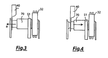
Fig. 3 and Fig. 4 respectively show a first and a second configurations of the system according to the present invention; -
Fig. 5 shows a detail of a support arm of the system according to the present invention; -
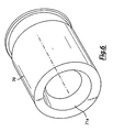
Fig. 6 shows a perspective view of a detail of a pulley belonging to the system according to the present invention. - Referring now to
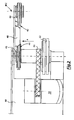
Fig. 1 ,reference numeral 10 designates as a whole a mechanical work sampling system for operating articulated extensions in vehicular applications. -
System 10 is based on the recognition of the practical usefulness of a variable geometry of a track of a trackedvehicle 30, and is especially designed for overcoming steps or stair ramps. - In particular, tracked
vehicle 30 has a first pair ofmain tracks 21, respectively positioned on the left side and on the right side of the vehicle itself, and a plurality ofsystems 10, each comprising at least one secondary track. - Therefore,
vehicle 30 shown inFig. 1 includes a second and a third pair ofsecondary tracks - the second pair of
secondary tracks 22 are positioned on a front part ofvehicle 30, wherein the second pair of secondary tracks include one track installed on the left side and one track installed on the right side; for this reason, a pair ofsystems 10 according to the present invention are fitted on the front part ofvehicle 30; - the third pair of
secondary tracks 23 are positioned on a rear part ofvehicle 30, wherein the third pair of secondary tracks include one track installed on the left side and one track installed on the right side; a pair ofsystems 10 according to the present invention are therefore also present at the rear ofvehicle 30. - The secondary tracks move in the same direction as
main tracks 21. - The second and third pairs of
secondary tracks support arms 40, each having afirst end 41 constrained to an axis coinciding with that of a driven or drive wheel carrying a track of the first pair ofmain tracks 21, and asecond end 42 on which a respective first drivenwheel 44 is installed, which is susceptible of tensioning the secondary track together with a second driven wheel 45 (not shown inFig. 1 because hidden bydrive wheel 32 of the main track), rotating about an axis parallel to that of the first drivenwheel 44. - In
Fig. 1 , for example, the third pair ofsecondary tracks 23 have respective left andright support arms 40, which are constrained to adriving wheel 32 of the pair ofmain tracks 21;driving wheel 32 is turned by at least onemain propulsor 50, schematically shown as a square box for simplicity. - Each one of
support arms 40 can rotate about thefirst end 41, so that the secondary tracks of the second and third pairs oftracks ground 100 on which trackedvehicle 30 is moving. -
Fig. 2 , which is a plan view of a detail ofFig. 1 , shows achassis 60 of the trackedvehicle 30, whereto a shaft is constrained on which drivingwheel 32 rotates, the latter receiving motion from themain propulsor 50 through adrive belt 51 turning on a couple of axes parallel to axis z. - The second driven
wheel 45 of the secondary track, axially positioned onsupport arm 40, is also connected to this shaft. - Each one of the
support arms 40 can slide with respect to the shaft in a direction orthogonal to its axis, i.e. it can slide sideways to the left and to the right with respect to the direction of forward motion of thevehicle 30, as shown inFig. 2 by arrow a, i.e. parallel to axis z. - Therefore, each one of
support arms 40 has a first and a second operating configurations. - In the first operating configuration, as shown in the detail of
Fig. 3 , a coupling takes place, for example and without limitation by means of bevel gears, betweensupport arm 40 andchassis 60. - On the contrary, the second operating configuration, as shown in the detail of
Fig. 4 , corresponds to a coupling betweensupport arm 40 andmain propulsor 50 which takes place through a drivenpulley 70 driven by said propulsor and mounted axially on the shaft. - When switching from the first to the second operating configuration, the first and second driven
wheels support arm 40 keep working in the axial position with respect to the arm itself; being idle, they can rotate with respect to supportarm 40 whenmain propulsor 50 is on. - However, while in the first operating
configuration support arm 40 is locked to a fixed angle α, in the second operatingconfiguration support arm 40 is rotated on thefirst end 41 and takes work offmain propulsor 50. - As previously described, the coupling between the
first end 41 ofsupport arm 40 and drivenpulley 70 occurs through the use of bevel gears; however, a similar system employs a pair of clutches arranged at the axis of rotation ofsupport arm 40. - In such a case, as shown in
Fig. 5 , thefirst end 41 ofsupport arm 40 has acylindrical body 41a which, when in use, is at least partially inserted in the body of the driven pulley;cylindrical body 41a ends with a hollow male truncatedconical section 41b. -
Driven pulley 70, shown inFig. 6 , is also hollow and has one end terminating with a female truncatedconical section 71a which, when in use, couples to the end ofcylindrical body 41a by contrast. - In the first operating configuration, the truncated conical ends do not touch each other, so that the arm is locked at a predefined angle.
- In the second operating configuration, instead, the truncated conical ends are brought near and therefore enter a configuration wherein they are mutually coupled by contrast; the driven pulley and
support arm 40 are thus coupled together, and the rotation ofsupport arm 40 can be governed throughmain propulsor 50. - Finally, system 1 according to the present invention is provided with limit switches (not shown) that may be linked to additional safety devices to ensure that
support arms 40 are used properly within the angular spaces required by a specific application and in accordance with the vehicle's dimensions. - The advantages of the mechanical work sampling system for operating articulated extensions in vehicular applications are apparent from the above description. In particular, it allows to change the position of the centre of gravity of a tracked vehicle, while at the same time allowing to overcome obstacles which traditionally might cause the vehicle to turn over or anyway jeopardize its stability.
- The system according to the present invention can be easily designed and manufactured, thus contributing to keeping the final cost of the tracked vehicle as low as possible.
- The system described so far may be subject to a number of variations, modifications and additions which are obvious to those skilled in the art, without however departing from the protection scope set forth in the appended claims.
- In particular, it is clear that the truncated conical couplings shown in the annexed drawings and described above may equivalently be replaced with clutching means arranged at the axis of rotation of the support arm.
Claims (7)
- A mechanical work sampling system (10) for the operation of extensions articulated in vehicular applications; the system is susceptible of being applied on a tracked vehicle (30) and comprises at least a supporting arm (40) and a secondary track (22; 23) associated to said supporting arm (40); said supporting arm (40) being configurable in rotation configuration within which it rotates with respect to a first end (41) through a sampling of work from a propulsor of said tracked,vehicle (30); said system comprises friction means susceptible of being coupled to an end of said supporting arm (40);
said friction means comprise at least a pulley (70);
said system is characterized in that said pulley (70) comprises a truncated conical section (71a) and wherein said supporting arm (40) has on its end a body (41a) ending with a truncated conical section; said truncated conical section (71a) of said pulley (70) and said truncated conical section (41b) of said body (41a) being susceptible of mutually coupling in use. - System according to claim 1, wherein said supporting arm comprises another configuration within which it is fixed with respect to said tracked vehicle (30).
- System according to claim 1, wherein said supporting arm (40) comprises also a second end (42) opposed with respect to said first end; said system (10) comprising also a first and second wheel (44, 45), positioned respectively upon said first and second end (41, 42) and upon which it is installed said secondary track (22; 23).
- System according to claim 1, wherein said truncated conical section (71a) of said pulley (70) and said truncated conical section (41b) of said body (41a) are respectively of male and female type or of female and male type.
- Tracked vehicle (30), comprising a mechanical work sampling system (10) for the operation of extensions articulated in vehicular applications according to claims 1-4.
- Tracked vehicle (30) according to claim 5, particularly designed for the overcoming steps and ramps, comprising a couple of main tracks (21) each one installed on at least a couple of wheels, and wherein for each wheel of said couple of wheels of each of said main tracks (21) is installed a system (10) according to claims 1-4.
- Tracked vehicle according to claim 5, susceptible in used of moving on a ground (100), and wherein said supporting arm (40) of said system (10), in said rotation configuration, varies an angle (α) between itself and said ground (100).
Priority Applications (1)
| Application Number | Priority Date | Filing Date | Title |
|---|---|---|---|
| PL12151345T PL2479088T3 (en) | 2011-01-20 | 2012-01-17 | Mechanical work sampling system for the operation of articulated extensions in vehicular applications. |
Applications Claiming Priority (1)
| Application Number | Priority Date | Filing Date | Title |
|---|---|---|---|
| ITTO2011A000037A IT1403799B1 (en) | 2011-01-20 | 2011-01-20 | MECHANICAL WITHDRAWAL SYSTEM FOR THE OPERATION OF ARTICULATED EXTENSIONS IN VEHICLE APPLICATIONS. |
Publications (2)
| Publication Number | Publication Date |
|---|---|
| EP2479088A1 EP2479088A1 (en) | 2012-07-25 |
| EP2479088B1 true EP2479088B1 (en) | 2013-10-16 |
Family
ID=43975617
Family Applications (1)
| Application Number | Title | Priority Date | Filing Date |
|---|---|---|---|
| EP12151345.1A Active EP2479088B1 (en) | 2011-01-20 | 2012-01-17 | Mechanical work sampling system for the operation of articulated extensions in vehicular applications. |
Country Status (10)
| Country | Link |
|---|---|
| US (1) | US8833493B2 (en) |
| EP (1) | EP2479088B1 (en) |
| CN (1) | CN102700635B (en) |
| CA (1) | CA2764485A1 (en) |
| ES (1) | ES2445022T3 (en) |
| IL (1) | IL217646A (en) |
| IN (1) | IN2012DE00156A (en) |
| IT (1) | IT1403799B1 (en) |
| PL (1) | PL2479088T3 (en) |
| SG (1) | SG182928A1 (en) |
Families Citing this family (10)
| Publication number | Priority date | Publication date | Assignee | Title |
|---|---|---|---|---|
| CN103610544B (en) * | 2013-10-24 | 2016-10-12 | 北京互邦之家爬楼车技术开发有限公司 | Folding telescopic stairs-mover chassis |
| CN103624765B (en) * | 2013-12-23 | 2015-08-19 | 哈尔滨工业大学 | A kind of modularization search and rescue robot of reconfigurable function |
| US9096281B1 (en) * | 2014-07-30 | 2015-08-04 | Engineering Services Inc. | Dual mode mobile robot |
| CN107235086B (en) * | 2017-06-02 | 2019-01-18 | 天津市龙眼机器人科技有限公司 | A kind of full topographical steps climbing robot |
| CN107539382A (en) * | 2017-09-08 | 2018-01-05 | 上海钧工机器人有限公司 | A kind of motion platform |
| CN109646199B (en) * | 2018-12-21 | 2020-09-04 | 杭州铭智云教育科技有限公司 | Electric wheelchair for improving use comfort |
| CN109515538B (en) * | 2018-12-29 | 2023-05-30 | 中国科学院沈阳自动化研究所 | Reconfigurable joint crawler composite mobile robot |
| CN109849011A (en) * | 2019-03-08 | 2019-06-07 | 哈尔滨工业大学 | A kind of dangerous material sampling robot |
| CN111547145A (en) * | 2020-05-26 | 2020-08-18 | 北京联博达科技有限公司 | Multi-mode driving crawler-type electric carrying device and method |
| CN111775134A (en) * | 2020-07-30 | 2020-10-16 | 嘉兴学院 | Inspection robot with obstacle crossing climbing mechanism and use method thereof |
Family Cites Families (9)
| Publication number | Priority date | Publication date | Assignee | Title |
|---|---|---|---|---|
| US3166138A (en) * | 1961-10-26 | 1965-01-19 | Jr Edward D Dunn | Stair climbing conveyance |
| US3288234A (en) * | 1964-08-17 | 1966-11-29 | Jack M Feliz | Stair climbing conveyance |
| US4932831A (en) * | 1988-09-26 | 1990-06-12 | Remotec, Inc. | All terrain mobile robot |
| US5443354A (en) * | 1992-07-20 | 1995-08-22 | The United States Of America As Represented By The Administrator Of The National Aeronautics And Space Administration | Hazardous materials emergency response mobile robot |
| US6263989B1 (en) * | 1998-03-27 | 2001-07-24 | Irobot Corporation | Robotic platform |
| IL163589A0 (en) * | 2004-08-17 | 2005-12-18 | Lev Kritman | Stair climbing apparatus |
| US7654348B2 (en) * | 2006-10-06 | 2010-02-02 | Irobot Corporation | Maneuvering robotic vehicles having a positionable sensor head |
| US8644991B2 (en) * | 2006-10-06 | 2014-02-04 | Irobot Corporation | Maneuvering robotic vehicles |
| CN101428652B (en) * | 2007-11-07 | 2010-06-02 | 中国科学院沈阳自动化研究所 | Movable robot for ice and snow surface |
-
2011
- 2011-01-20 IT ITTO2011A000037A patent/IT1403799B1/en active
-
2012
- 2012-01-17 PL PL12151345T patent/PL2479088T3/en unknown
- 2012-01-17 EP EP12151345.1A patent/EP2479088B1/en active Active
- 2012-01-17 ES ES12151345.1T patent/ES2445022T3/en active Active
- 2012-01-17 US US13/351,905 patent/US8833493B2/en active Active
- 2012-01-17 CA CA2764485A patent/CA2764485A1/en not_active Abandoned
- 2012-01-18 SG SG2012004206A patent/SG182928A1/en unknown
- 2012-01-19 IL IL217646A patent/IL217646A/en active IP Right Grant
- 2012-01-19 IN IN156DE2012 patent/IN2012DE00156A/en unknown
- 2012-01-20 CN CN201210124680.9A patent/CN102700635B/en not_active Expired - Fee Related
Also Published As
| Publication number | Publication date |
|---|---|
| US8833493B2 (en) | 2014-09-16 |
| ES2445022T3 (en) | 2014-02-27 |
| SG182928A1 (en) | 2012-08-30 |
| CN102700635A (en) | 2012-10-03 |
| CN102700635B (en) | 2016-08-03 |
| US20120186886A1 (en) | 2012-07-26 |
| PL2479088T3 (en) | 2014-05-30 |
| IN2012DE00156A (en) | 2015-06-12 |
| EP2479088A1 (en) | 2012-07-25 |
| CA2764485A1 (en) | 2012-07-20 |
| ITTO20110037A1 (en) | 2012-07-21 |
| IT1403799B1 (en) | 2013-10-31 |
| IL217646A0 (en) | 2012-06-28 |
| IL217646A (en) | 2016-10-31 |
Similar Documents
| Publication | Publication Date | Title |
|---|---|---|
| EP2479088B1 (en) | Mechanical work sampling system for the operation of articulated extensions in vehicular applications. | |
| JP6870032B2 (en) | Hinged vehicle chassis | |
| EP2726256B1 (en) | Mobile robot | |
| US9586633B2 (en) | Ground robot drive system | |
| KR101049626B1 (en) | robot | |
| EP3660619B1 (en) | Two wheel automatic guided vehicles used in combination | |
| KR101204147B1 (en) | Caster wheel mechanism having dual offset structure and omnidirectional mobile robot using the same | |
| CN107922020B (en) | Traveling apparatus and control method thereof | |
| CN107628134B (en) | Compound drive type spring coupling type active hinged towing robot | |
| WO2015035095A1 (en) | Three-wheeled mobile robot | |
| US20200070338A1 (en) | Multidirectional locomotive module with omnidirectional bending | |
| EP1918152A2 (en) | A drive unit and a powered vehicle | |
| JPH0717442A (en) | Vehicle for omnidirectional movement | |
| CN114585552B (en) | Omnidirectional line following autonomous vehicle | |
| JP2008126998A (en) | Steering device for completely concentrating axle directions of whole wheels | |
| JP2023044065A (en) | moving body | |
| CN201472053U (en) | Integrated bevel gear reversal Mecanum wheel | |
| CN113635762A (en) | Chassis assembly | |
| JPWO2021074843A5 (en) |
Legal Events
| Date | Code | Title | Description |
|---|---|---|---|
| PUAI | Public reference made under article 153(3) epc to a published international application that has entered the european phase |
Free format text: ORIGINAL CODE: 0009012 |
|
| AK | Designated contracting states |
Kind code of ref document: A1 Designated state(s): AL AT BE BG CH CY CZ DE DK EE ES FI FR GB GR HR HU IE IS IT LI LT LU LV MC MK MT NL NO PL PT RO RS SE SI SK SM TR |
|
| AX | Request for extension of the european patent |
Extension state: BA ME |
|
| 17P | Request for examination filed |
Effective date: 20130108 |
|
| GRAP | Despatch of communication of intention to grant a patent |
Free format text: ORIGINAL CODE: EPIDOSNIGR1 |
|
| INTG | Intention to grant announced |
Effective date: 20130516 |
|
| GRAS | Grant fee paid |
Free format text: ORIGINAL CODE: EPIDOSNIGR3 |
|
| GRAA | (expected) grant |
Free format text: ORIGINAL CODE: 0009210 |
|
| AK | Designated contracting states |
Kind code of ref document: B1 Designated state(s): AL AT BE BG CH CY CZ DE DK EE ES FI FR GB GR HR HU IE IS IT LI LT LU LV MC MK MT NL NO PL PT RO RS SE SI SK SM TR |
|
| REG | Reference to a national code |
Ref country code: GB Ref legal event code: FG4D |
|
| REG | Reference to a national code |
Ref country code: CH Ref legal event code: EP |
|
| REG | Reference to a national code |
Ref country code: IE Ref legal event code: FG4D |
|
| REG | Reference to a national code |
Ref country code: AT Ref legal event code: REF Ref document number: 636346 Country of ref document: AT Kind code of ref document: T Effective date: 20131115 |
|
| REG | Reference to a national code |
Ref country code: DE Ref legal event code: R096 Ref document number: 602012000377 Country of ref document: DE Effective date: 20131212 |
|
| REG | Reference to a national code |
Ref country code: CH Ref legal event code: NV Representative=s name: ROTTMANN, ZIMMERMANN + PARTNER AG, CH |
|
| REG | Reference to a national code |
Ref country code: NL Ref legal event code: T3 |
|
| REG | Reference to a national code |
Ref country code: NL Ref legal event code: T3 |
|
| REG | Reference to a national code |
Ref country code: ES Ref legal event code: FG2A Ref document number: 2445022 Country of ref document: ES Kind code of ref document: T3 Effective date: 20140227 |
|
| REG | Reference to a national code |
Ref country code: LT Ref legal event code: MG4D |
|
| PG25 | Lapsed in a contracting state [announced via postgrant information from national office to epo] |
Ref country code: LT Free format text: LAPSE BECAUSE OF FAILURE TO SUBMIT A TRANSLATION OF THE DESCRIPTION OR TO PAY THE FEE WITHIN THE PRESCRIBED TIME-LIMIT Effective date: 20131016 Ref country code: HR Free format text: LAPSE BECAUSE OF FAILURE TO SUBMIT A TRANSLATION OF THE DESCRIPTION OR TO PAY THE FEE WITHIN THE PRESCRIBED TIME-LIMIT Effective date: 20131016 Ref country code: IS Free format text: LAPSE BECAUSE OF FAILURE TO SUBMIT A TRANSLATION OF THE DESCRIPTION OR TO PAY THE FEE WITHIN THE PRESCRIBED TIME-LIMIT Effective date: 20140216 Ref country code: FI Free format text: LAPSE BECAUSE OF FAILURE TO SUBMIT A TRANSLATION OF THE DESCRIPTION OR TO PAY THE FEE WITHIN THE PRESCRIBED TIME-LIMIT Effective date: 20131016 Ref country code: SE Free format text: LAPSE BECAUSE OF FAILURE TO SUBMIT A TRANSLATION OF THE DESCRIPTION OR TO PAY THE FEE WITHIN THE PRESCRIBED TIME-LIMIT Effective date: 20131016 Ref country code: NO Free format text: LAPSE BECAUSE OF FAILURE TO SUBMIT A TRANSLATION OF THE DESCRIPTION OR TO PAY THE FEE WITHIN THE PRESCRIBED TIME-LIMIT Effective date: 20140116 |
|
| PG25 | Lapsed in a contracting state [announced via postgrant information from national office to epo] |
Ref country code: LV Free format text: LAPSE BECAUSE OF FAILURE TO SUBMIT A TRANSLATION OF THE DESCRIPTION OR TO PAY THE FEE WITHIN THE PRESCRIBED TIME-LIMIT Effective date: 20131016 Ref country code: RS Free format text: LAPSE BECAUSE OF FAILURE TO SUBMIT A TRANSLATION OF THE DESCRIPTION OR TO PAY THE FEE WITHIN THE PRESCRIBED TIME-LIMIT Effective date: 20131016 Ref country code: CY Free format text: LAPSE BECAUSE OF FAILURE TO SUBMIT A TRANSLATION OF THE DESCRIPTION OR TO PAY THE FEE WITHIN THE PRESCRIBED TIME-LIMIT Effective date: 20131016 |
|
| REG | Reference to a national code |
Ref country code: PL Ref legal event code: T3 |
|
| PG25 | Lapsed in a contracting state [announced via postgrant information from national office to epo] |
Ref country code: PT Free format text: LAPSE BECAUSE OF FAILURE TO SUBMIT A TRANSLATION OF THE DESCRIPTION OR TO PAY THE FEE WITHIN THE PRESCRIBED TIME-LIMIT Effective date: 20140217 |
|
| REG | Reference to a national code |
Ref country code: DE Ref legal event code: R097 Ref document number: 602012000377 Country of ref document: DE |
|
| PG25 | Lapsed in a contracting state [announced via postgrant information from national office to epo] |
Ref country code: EE Free format text: LAPSE BECAUSE OF FAILURE TO SUBMIT A TRANSLATION OF THE DESCRIPTION OR TO PAY THE FEE WITHIN THE PRESCRIBED TIME-LIMIT Effective date: 20131016 |
|
| PLBE | No opposition filed within time limit |
Free format text: ORIGINAL CODE: 0009261 |
|
| STAA | Information on the status of an ep patent application or granted ep patent |
Free format text: STATUS: NO OPPOSITION FILED WITHIN TIME LIMIT |
|
| PG25 | Lapsed in a contracting state [announced via postgrant information from national office to epo] |
Ref country code: SK Free format text: LAPSE BECAUSE OF FAILURE TO SUBMIT A TRANSLATION OF THE DESCRIPTION OR TO PAY THE FEE WITHIN THE PRESCRIBED TIME-LIMIT Effective date: 20131016 Ref country code: LU Free format text: LAPSE BECAUSE OF FAILURE TO SUBMIT A TRANSLATION OF THE DESCRIPTION OR TO PAY THE FEE WITHIN THE PRESCRIBED TIME-LIMIT Effective date: 20140117 Ref country code: CZ Free format text: LAPSE BECAUSE OF FAILURE TO SUBMIT A TRANSLATION OF THE DESCRIPTION OR TO PAY THE FEE WITHIN THE PRESCRIBED TIME-LIMIT Effective date: 20131016 Ref country code: RO Free format text: LAPSE BECAUSE OF FAILURE TO SUBMIT A TRANSLATION OF THE DESCRIPTION OR TO PAY THE FEE WITHIN THE PRESCRIBED TIME-LIMIT Effective date: 20131016 |
|
| 26N | No opposition filed |
Effective date: 20140717 |
|
| PG25 | Lapsed in a contracting state [announced via postgrant information from national office to epo] |
Ref country code: DK Free format text: LAPSE BECAUSE OF FAILURE TO SUBMIT A TRANSLATION OF THE DESCRIPTION OR TO PAY THE FEE WITHIN THE PRESCRIBED TIME-LIMIT Effective date: 20131016 |
|
| REG | Reference to a national code |
Ref country code: DE Ref legal event code: R097 Ref document number: 602012000377 Country of ref document: DE Effective date: 20140717 |
|
| REG | Reference to a national code |
Ref country code: FR Ref legal event code: ST Effective date: 20140930 |
|
| REG | Reference to a national code |
Ref country code: IE Ref legal event code: MM4A |
|
| PG25 | Lapsed in a contracting state [announced via postgrant information from national office to epo] |
Ref country code: FR Free format text: LAPSE BECAUSE OF NON-PAYMENT OF DUE FEES Effective date: 20140131 |
|
| PG25 | Lapsed in a contracting state [announced via postgrant information from national office to epo] |
Ref country code: IE Free format text: LAPSE BECAUSE OF NON-PAYMENT OF DUE FEES Effective date: 20140117 |
|
| PG25 | Lapsed in a contracting state [announced via postgrant information from national office to epo] |
Ref country code: SI Free format text: LAPSE BECAUSE OF FAILURE TO SUBMIT A TRANSLATION OF THE DESCRIPTION OR TO PAY THE FEE WITHIN THE PRESCRIBED TIME-LIMIT Effective date: 20131016 |
|
| PG25 | Lapsed in a contracting state [announced via postgrant information from national office to epo] |
Ref country code: MC Free format text: LAPSE BECAUSE OF FAILURE TO SUBMIT A TRANSLATION OF THE DESCRIPTION OR TO PAY THE FEE WITHIN THE PRESCRIBED TIME-LIMIT Effective date: 20131016 |
|
| PGFP | Annual fee paid to national office [announced via postgrant information from national office to epo] |
Ref country code: BE Payment date: 20150112 Year of fee payment: 4 |
|
| PG25 | Lapsed in a contracting state [announced via postgrant information from national office to epo] |
Ref country code: MT Free format text: LAPSE BECAUSE OF FAILURE TO SUBMIT A TRANSLATION OF THE DESCRIPTION OR TO PAY THE FEE WITHIN THE PRESCRIBED TIME-LIMIT Effective date: 20131016 |
|
| PG25 | Lapsed in a contracting state [announced via postgrant information from national office to epo] |
Ref country code: SM Free format text: LAPSE BECAUSE OF FAILURE TO SUBMIT A TRANSLATION OF THE DESCRIPTION OR TO PAY THE FEE WITHIN THE PRESCRIBED TIME-LIMIT Effective date: 20131016 |
|
| PGFP | Annual fee paid to national office [announced via postgrant information from national office to epo] |
Ref country code: CH Payment date: 20160111 Year of fee payment: 5 |
|
| PG25 | Lapsed in a contracting state [announced via postgrant information from national office to epo] |
Ref country code: BE Free format text: LAPSE BECAUSE OF NON-PAYMENT OF DUE FEES Effective date: 20160131 |
|
| PG25 | Lapsed in a contracting state [announced via postgrant information from national office to epo] |
Ref country code: BG Free format text: LAPSE BECAUSE OF FAILURE TO SUBMIT A TRANSLATION OF THE DESCRIPTION OR TO PAY THE FEE WITHIN THE PRESCRIBED TIME-LIMIT Effective date: 20131016 Ref country code: GR Free format text: LAPSE BECAUSE OF FAILURE TO SUBMIT A TRANSLATION OF THE DESCRIPTION OR TO PAY THE FEE WITHIN THE PRESCRIBED TIME-LIMIT Effective date: 20140117 |
|
| PG25 | Lapsed in a contracting state [announced via postgrant information from national office to epo] |
Ref country code: TR Free format text: LAPSE BECAUSE OF FAILURE TO SUBMIT A TRANSLATION OF THE DESCRIPTION OR TO PAY THE FEE WITHIN THE PRESCRIBED TIME-LIMIT Effective date: 20131016 Ref country code: HU Free format text: LAPSE BECAUSE OF FAILURE TO SUBMIT A TRANSLATION OF THE DESCRIPTION OR TO PAY THE FEE WITHIN THE PRESCRIBED TIME-LIMIT; INVALID AB INITIO Effective date: 20120117 |
|
| GBPC | Gb: european patent ceased through non-payment of renewal fee |
Effective date: 20160117 |
|
| PG25 | Lapsed in a contracting state [announced via postgrant information from national office to epo] |
Ref country code: GB Free format text: LAPSE BECAUSE OF NON-PAYMENT OF DUE FEES Effective date: 20160117 |
|
| REG | Reference to a national code |
Ref country code: CH Ref legal event code: PCAR Free format text: NEW ADDRESS: GARTENSTRASSE 28 A, 5400 BADEN (CH) |
|
| REG | Reference to a national code |
Ref country code: CH Ref legal event code: PL |
|
| PG25 | Lapsed in a contracting state [announced via postgrant information from national office to epo] |
Ref country code: LI Free format text: LAPSE BECAUSE OF NON-PAYMENT OF DUE FEES Effective date: 20170131 Ref country code: CH Free format text: LAPSE BECAUSE OF NON-PAYMENT OF DUE FEES Effective date: 20170131 |
|
| REG | Reference to a national code |
Ref country code: AT Ref legal event code: MM01 Ref document number: 636346 Country of ref document: AT Kind code of ref document: T Effective date: 20170117 |
|
| PG25 | Lapsed in a contracting state [announced via postgrant information from national office to epo] |
Ref country code: AT Free format text: LAPSE BECAUSE OF NON-PAYMENT OF DUE FEES Effective date: 20170117 |
|
| PG25 | Lapsed in a contracting state [announced via postgrant information from national office to epo] |
Ref country code: MK Free format text: LAPSE BECAUSE OF FAILURE TO SUBMIT A TRANSLATION OF THE DESCRIPTION OR TO PAY THE FEE WITHIN THE PRESCRIBED TIME-LIMIT Effective date: 20131016 |
|
| PG25 | Lapsed in a contracting state [announced via postgrant information from national office to epo] |
Ref country code: AL Free format text: LAPSE BECAUSE OF FAILURE TO SUBMIT A TRANSLATION OF THE DESCRIPTION OR TO PAY THE FEE WITHIN THE PRESCRIBED TIME-LIMIT Effective date: 20131016 |
|
| PGFP | Annual fee paid to national office [announced via postgrant information from national office to epo] |
Ref country code: ES Payment date: 20230216 Year of fee payment: 12 |
|
| PGFP | Annual fee paid to national office [announced via postgrant information from national office to epo] |
Ref country code: PL Payment date: 20230110 Year of fee payment: 12 Ref country code: IT Payment date: 20230112 Year of fee payment: 12 Ref country code: DE Payment date: 20230119 Year of fee payment: 12 |
|
| PGFP | Annual fee paid to national office [announced via postgrant information from national office to epo] |
Ref country code: NL Payment date: 20230124 Year of fee payment: 12 |
|
| PGFP | Annual fee paid to national office [announced via postgrant information from national office to epo] |
Ref country code: NL Payment date: 20240123 Year of fee payment: 13 |
|
| PGFP | Annual fee paid to national office [announced via postgrant information from national office to epo] |
Ref country code: ES Payment date: 20240216 Year of fee payment: 13 |