EP4088807B1 - Élimination d'impuretés d'hydrogène dans des flux gazeux - Google Patents
Élimination d'impuretés d'hydrogène dans des flux gazeux Download PDFInfo
- Publication number
- EP4088807B1 EP4088807B1 EP22174903.9A EP22174903A EP4088807B1 EP 4088807 B1 EP4088807 B1 EP 4088807B1 EP 22174903 A EP22174903 A EP 22174903A EP 4088807 B1 EP4088807 B1 EP 4088807B1
- Authority
- EP
- European Patent Office
- Prior art keywords
- hopcalite
- catalyst
- hydrogen
- layer
- gas
- Prior art date
- Legal status (The legal status is an assumption and is not a legal conclusion. Google has not performed a legal analysis and makes no representation as to the accuracy of the status listed.)
- Active
Links
- 239000001257 hydrogen Substances 0.000 title claims description 164
- 229910052739 hydrogen Inorganic materials 0.000 title claims description 164
- 239000007789 gas Substances 0.000 title claims description 152
- UFHFLCQGNIYNRP-UHFFFAOYSA-N Hydrogen Chemical compound [H][H] UFHFLCQGNIYNRP-UHFFFAOYSA-N 0.000 title claims description 143
- 239000012535 impurity Substances 0.000 title claims description 36
- 239000003054 catalyst Substances 0.000 claims description 258
- CURLTUGMZLYLDI-UHFFFAOYSA-N Carbon dioxide Chemical compound O=C=O CURLTUGMZLYLDI-UHFFFAOYSA-N 0.000 claims description 199
- 239000010410 layer Substances 0.000 claims description 136
- 239000010949 copper Substances 0.000 claims description 112
- UGFAIRIUMAVXCW-UHFFFAOYSA-N Carbon monoxide Chemical compound [O+]#[C-] UGFAIRIUMAVXCW-UHFFFAOYSA-N 0.000 claims description 109
- 229910002091 carbon monoxide Inorganic materials 0.000 claims description 109
- 229910002092 carbon dioxide Inorganic materials 0.000 claims description 103
- 239000001569 carbon dioxide Substances 0.000 claims description 96
- XLYOFNOQVPJJNP-UHFFFAOYSA-N water Substances O XLYOFNOQVPJJNP-UHFFFAOYSA-N 0.000 claims description 84
- 229910001868 water Inorganic materials 0.000 claims description 83
- 239000011572 manganese Substances 0.000 claims description 64
- 239000003463 adsorbent Substances 0.000 claims description 57
- 238000000034 method Methods 0.000 claims description 45
- 230000008569 process Effects 0.000 claims description 43
- RYGMFSIKBFXOCR-UHFFFAOYSA-N Copper Chemical compound [Cu] RYGMFSIKBFXOCR-UHFFFAOYSA-N 0.000 claims description 41
- 229910052802 copper Inorganic materials 0.000 claims description 41
- 238000001179 sorption measurement Methods 0.000 claims description 40
- PWHULOQIROXLJO-UHFFFAOYSA-N Manganese Chemical compound [Mn] PWHULOQIROXLJO-UHFFFAOYSA-N 0.000 claims description 37
- 229910052748 manganese Inorganic materials 0.000 claims description 37
- 239000000463 material Substances 0.000 claims description 34
- 239000002356 single layer Substances 0.000 claims description 22
- 150000002431 hydrogen Chemical class 0.000 claims description 21
- 239000011148 porous material Substances 0.000 claims description 11
- 238000011144 upstream manufacturing Methods 0.000 claims description 9
- 230000008929 regeneration Effects 0.000 description 46
- 238000011069 regeneration method Methods 0.000 description 46
- IJGRMHOSHXDMSA-UHFFFAOYSA-N Atomic nitrogen Chemical compound N#N IJGRMHOSHXDMSA-UHFFFAOYSA-N 0.000 description 41
- 238000007254 oxidation reaction Methods 0.000 description 29
- 230000003647 oxidation Effects 0.000 description 26
- 239000000047 product Substances 0.000 description 25
- 229910052757 nitrogen Inorganic materials 0.000 description 20
- PNEYBMLMFCGWSK-UHFFFAOYSA-N aluminium oxide Inorganic materials [O-2].[O-2].[O-2].[Al+3].[Al+3] PNEYBMLMFCGWSK-UHFFFAOYSA-N 0.000 description 17
- QVGXLLKOCUKJST-UHFFFAOYSA-N atomic oxygen Chemical compound [O] QVGXLLKOCUKJST-UHFFFAOYSA-N 0.000 description 15
- 239000001301 oxygen Substances 0.000 description 15
- 229910052760 oxygen Inorganic materials 0.000 description 15
- 238000010926 purge Methods 0.000 description 11
- 238000004821 distillation Methods 0.000 description 10
- 239000000203 mixture Substances 0.000 description 10
- 230000008901 benefit Effects 0.000 description 9
- 229910000510 noble metal Inorganic materials 0.000 description 8
- 239000010970 precious metal Substances 0.000 description 8
- 238000000746 purification Methods 0.000 description 8
- 229910052799 carbon Inorganic materials 0.000 description 7
- 238000001816 cooling Methods 0.000 description 7
- 238000002474 experimental method Methods 0.000 description 7
- 238000010438 heat treatment Methods 0.000 description 7
- 230000007246 mechanism Effects 0.000 description 7
- 229910052751 metal Inorganic materials 0.000 description 7
- 239000002184 metal Substances 0.000 description 7
- 238000013459 approach Methods 0.000 description 6
- 238000006243 chemical reaction Methods 0.000 description 6
- VUZPPFZMUPKLLV-UHFFFAOYSA-N methane;hydrate Chemical compound C.O VUZPPFZMUPKLLV-UHFFFAOYSA-N 0.000 description 6
- 230000036961 partial effect Effects 0.000 description 6
- 238000013461 design Methods 0.000 description 5
- 238000004519 manufacturing process Methods 0.000 description 5
- 238000005259 measurement Methods 0.000 description 5
- 238000000926 separation method Methods 0.000 description 5
- CDBYLPFSWZWCQE-UHFFFAOYSA-L Sodium Carbonate Chemical compound [Na+].[Na+].[O-]C([O-])=O CDBYLPFSWZWCQE-UHFFFAOYSA-L 0.000 description 4
- 229910021536 Zeolite Inorganic materials 0.000 description 4
- HNPSIPDUKPIQMN-UHFFFAOYSA-N dioxosilane;oxo(oxoalumanyloxy)alumane Chemical compound O=[Si]=O.O=[Al]O[Al]=O HNPSIPDUKPIQMN-UHFFFAOYSA-N 0.000 description 4
- 230000000694 effects Effects 0.000 description 4
- 238000011068 loading method Methods 0.000 description 4
- 239000010457 zeolite Substances 0.000 description 4
- ZLMJMSJWJFRBEC-UHFFFAOYSA-N Potassium Chemical compound [K] ZLMJMSJWJFRBEC-UHFFFAOYSA-N 0.000 description 3
- VYPSYNLAJGMNEJ-UHFFFAOYSA-N Silicium dioxide Chemical compound O=[Si]=O VYPSYNLAJGMNEJ-UHFFFAOYSA-N 0.000 description 3
- 230000003197 catalytic effect Effects 0.000 description 3
- XTVVROIMIGLXTD-UHFFFAOYSA-N copper(II) nitrate Chemical compound [Cu+2].[O-][N+]([O-])=O.[O-][N+]([O-])=O XTVVROIMIGLXTD-UHFFFAOYSA-N 0.000 description 3
- 230000007423 decrease Effects 0.000 description 3
- 230000003247 decreasing effect Effects 0.000 description 3
- 238000005516 engineering process Methods 0.000 description 3
- 239000002808 molecular sieve Substances 0.000 description 3
- 239000008188 pellet Substances 0.000 description 3
- 229910052700 potassium Inorganic materials 0.000 description 3
- 239000011591 potassium Substances 0.000 description 3
- 230000002829 reductive effect Effects 0.000 description 3
- URGAHOPLAPQHLN-UHFFFAOYSA-N sodium aluminosilicate Chemical compound [Na+].[Al+3].[O-][Si]([O-])=O.[O-][Si]([O-])=O URGAHOPLAPQHLN-UHFFFAOYSA-N 0.000 description 3
- 238000012360 testing method Methods 0.000 description 3
- 239000002912 waste gas Substances 0.000 description 3
- OKTJSMMVPCPJKN-UHFFFAOYSA-N Carbon Chemical compound [C] OKTJSMMVPCPJKN-UHFFFAOYSA-N 0.000 description 2
- QPLDLSVMHZLSFG-UHFFFAOYSA-N Copper oxide Chemical compound [Cu]=O QPLDLSVMHZLSFG-UHFFFAOYSA-N 0.000 description 2
- DGAQECJNVWCQMB-PUAWFVPOSA-M Ilexoside XXIX Chemical compound C[C@@H]1CC[C@@]2(CC[C@@]3(C(=CC[C@H]4[C@]3(CC[C@@H]5[C@@]4(CC[C@@H](C5(C)C)OS(=O)(=O)[O-])C)C)[C@@H]2[C@]1(C)O)C)C(=O)O[C@H]6[C@@H]([C@H]([C@@H]([C@H](O6)CO)O)O)O.[Na+] DGAQECJNVWCQMB-PUAWFVPOSA-M 0.000 description 2
- KDLHZDBZIXYQEI-UHFFFAOYSA-N Palladium Chemical compound [Pd] KDLHZDBZIXYQEI-UHFFFAOYSA-N 0.000 description 2
- XUIMIQQOPSSXEZ-UHFFFAOYSA-N Silicon Chemical compound [Si] XUIMIQQOPSSXEZ-UHFFFAOYSA-N 0.000 description 2
- 230000015572 biosynthetic process Effects 0.000 description 2
- 230000000052 comparative effect Effects 0.000 description 2
- 238000003795 desorption Methods 0.000 description 2
- PUFKGWVZPFANLN-UHFFFAOYSA-N dioxomanganese oxocopper Chemical group O=[Cu].O=[Mn]=O PUFKGWVZPFANLN-UHFFFAOYSA-N 0.000 description 2
- 238000011067 equilibration Methods 0.000 description 2
- AMWRITDGCCNYAT-UHFFFAOYSA-L hydroxy(oxo)manganese;manganese Chemical compound [Mn].O[Mn]=O.O[Mn]=O AMWRITDGCCNYAT-UHFFFAOYSA-L 0.000 description 2
- NUJOXMJBOLGQSY-UHFFFAOYSA-N manganese dioxide Chemical compound O=[Mn]=O NUJOXMJBOLGQSY-UHFFFAOYSA-N 0.000 description 2
- MIVBAHRSNUNMPP-UHFFFAOYSA-N manganese(2+);dinitrate Chemical compound [Mn+2].[O-][N+]([O-])=O.[O-][N+]([O-])=O MIVBAHRSNUNMPP-UHFFFAOYSA-N 0.000 description 2
- 229910044991 metal oxide Inorganic materials 0.000 description 2
- 150000004706 metal oxides Chemical class 0.000 description 2
- 230000001590 oxidative effect Effects 0.000 description 2
- 239000002245 particle Substances 0.000 description 2
- BASFCYQUMIYNBI-UHFFFAOYSA-N platinum Chemical compound [Pt] BASFCYQUMIYNBI-UHFFFAOYSA-N 0.000 description 2
- 239000002574 poison Substances 0.000 description 2
- 231100000614 poison Toxicity 0.000 description 2
- 239000000843 powder Substances 0.000 description 2
- 230000009257 reactivity Effects 0.000 description 2
- 230000001172 regenerating effect Effects 0.000 description 2
- 238000005070 sampling Methods 0.000 description 2
- 229920006395 saturated elastomer Polymers 0.000 description 2
- 230000035945 sensitivity Effects 0.000 description 2
- 239000010703 silicon Substances 0.000 description 2
- 229910052710 silicon Inorganic materials 0.000 description 2
- 239000011734 sodium Substances 0.000 description 2
- 229910052708 sodium Inorganic materials 0.000 description 2
- 229910000029 sodium carbonate Inorganic materials 0.000 description 2
- 239000007787 solid Substances 0.000 description 2
- 239000000243 solution Substances 0.000 description 2
- 239000000126 substance Substances 0.000 description 2
- 238000004846 x-ray emission Methods 0.000 description 2
- OCKGFTQIICXDQW-ZEQRLZLVSA-N 5-[(1r)-1-hydroxy-2-[4-[(2r)-2-hydroxy-2-(4-methyl-1-oxo-3h-2-benzofuran-5-yl)ethyl]piperazin-1-yl]ethyl]-4-methyl-3h-2-benzofuran-1-one Chemical compound C1=C2C(=O)OCC2=C(C)C([C@@H](O)CN2CCN(CC2)C[C@H](O)C2=CC=C3C(=O)OCC3=C2C)=C1 OCKGFTQIICXDQW-ZEQRLZLVSA-N 0.000 description 1
- OYPRJOBELJOOCE-UHFFFAOYSA-N Calcium Chemical compound [Ca] OYPRJOBELJOOCE-UHFFFAOYSA-N 0.000 description 1
- 239000005751 Copper oxide Substances 0.000 description 1
- MYMOFIZGZYHOMD-UHFFFAOYSA-N Dioxygen Chemical compound O=O MYMOFIZGZYHOMD-UHFFFAOYSA-N 0.000 description 1
- KJTLSVCANCCWHF-UHFFFAOYSA-N Ruthenium Chemical compound [Ru] KJTLSVCANCCWHF-UHFFFAOYSA-N 0.000 description 1
- 229910000831 Steel Inorganic materials 0.000 description 1
- 230000000274 adsorptive effect Effects 0.000 description 1
- 239000004411 aluminium Substances 0.000 description 1
- 229910052782 aluminium Inorganic materials 0.000 description 1
- XAGFODPZIPBFFR-UHFFFAOYSA-N aluminium Chemical compound [Al] XAGFODPZIPBFFR-UHFFFAOYSA-N 0.000 description 1
- 239000007864 aqueous solution Substances 0.000 description 1
- 238000009835 boiling Methods 0.000 description 1
- 239000006227 byproduct Substances 0.000 description 1
- 239000011575 calcium Substances 0.000 description 1
- 229910052791 calcium Inorganic materials 0.000 description 1
- 238000006555 catalytic reaction Methods 0.000 description 1
- 238000001311 chemical methods and process Methods 0.000 description 1
- 238000009833 condensation Methods 0.000 description 1
- 230000005494 condensation Effects 0.000 description 1
- 235000009508 confectionery Nutrition 0.000 description 1
- 238000010276 construction Methods 0.000 description 1
- 239000000112 cooling gas Substances 0.000 description 1
- 229910000431 copper oxide Inorganic materials 0.000 description 1
- 125000004122 cyclic group Chemical group 0.000 description 1
- 229910001882 dioxygen Inorganic materials 0.000 description 1
- 238000011156 evaluation Methods 0.000 description 1
- 230000002349 favourable effect Effects 0.000 description 1
- 239000012530 fluid Substances 0.000 description 1
- 239000008187 granular material Substances 0.000 description 1
- -1 i.e. Chemical compound 0.000 description 1
- 238000009434 installation Methods 0.000 description 1
- 230000000670 limiting effect Effects 0.000 description 1
- 238000012986 modification Methods 0.000 description 1
- 230000004048 modification Effects 0.000 description 1
- 229910052756 noble gas Inorganic materials 0.000 description 1
- 150000002835 noble gases Chemical class 0.000 description 1
- 239000007800 oxidant agent Substances 0.000 description 1
- 229910052763 palladium Inorganic materials 0.000 description 1
- 238000005191 phase separation Methods 0.000 description 1
- 229910052697 platinum Inorganic materials 0.000 description 1
- 231100000572 poisoning Toxicity 0.000 description 1
- 230000000607 poisoning effect Effects 0.000 description 1
- 238000000634 powder X-ray diffraction Methods 0.000 description 1
- 238000002360 preparation method Methods 0.000 description 1
- 238000002203 pretreatment Methods 0.000 description 1
- 238000012545 processing Methods 0.000 description 1
- 238000011084 recovery Methods 0.000 description 1
- 230000009467 reduction Effects 0.000 description 1
- 230000000717 retained effect Effects 0.000 description 1
- 238000009420 retrofitting Methods 0.000 description 1
- 229910052703 rhodium Inorganic materials 0.000 description 1
- 239000010948 rhodium Substances 0.000 description 1
- MHOVAHRLVXNVSD-UHFFFAOYSA-N rhodium atom Chemical compound [Rh] MHOVAHRLVXNVSD-UHFFFAOYSA-N 0.000 description 1
- 229910052707 ruthenium Inorganic materials 0.000 description 1
- 238000007789 sealing Methods 0.000 description 1
- 238000005204 segregation Methods 0.000 description 1
- 239000004065 semiconductor Substances 0.000 description 1
- 239000000741 silica gel Substances 0.000 description 1
- 229910002027 silica gel Inorganic materials 0.000 description 1
- 239000000377 silicon dioxide Substances 0.000 description 1
- 239000010959 steel Substances 0.000 description 1
- 239000011800 void material Substances 0.000 description 1
- 235000012431 wafers Nutrition 0.000 description 1
- 239000002699 waste material Substances 0.000 description 1
- 238000000177 wavelength dispersive X-ray spectroscopy Methods 0.000 description 1
- 230000004580 weight loss Effects 0.000 description 1
- 238000004876 x-ray fluorescence Methods 0.000 description 1
Images


Classifications
-
- B—PERFORMING OPERATIONS; TRANSPORTING
- B01—PHYSICAL OR CHEMICAL PROCESSES OR APPARATUS IN GENERAL
- B01D—SEPARATION
- B01D53/00—Separation of gases or vapours; Recovering vapours of volatile solvents from gases; Chemical or biological purification of waste gases, e.g. engine exhaust gases, smoke, fumes, flue gases, aerosols
- B01D53/34—Chemical or biological purification of waste gases
- B01D53/74—General processes for purification of waste gases; Apparatus or devices specially adapted therefor
- B01D53/86—Catalytic processes
- B01D53/8671—Removing components of defined structure not provided for in B01D53/8603 - B01D53/8668
-
- B—PERFORMING OPERATIONS; TRANSPORTING
- B01—PHYSICAL OR CHEMICAL PROCESSES OR APPARATUS IN GENERAL
- B01D—SEPARATION
- B01D53/00—Separation of gases or vapours; Recovering vapours of volatile solvents from gases; Chemical or biological purification of waste gases, e.g. engine exhaust gases, smoke, fumes, flue gases, aerosols
- B01D53/34—Chemical or biological purification of waste gases
- B01D53/74—General processes for purification of waste gases; Apparatus or devices specially adapted therefor
- B01D53/86—Catalytic processes
-
- C—CHEMISTRY; METALLURGY
- C01—INORGANIC CHEMISTRY
- C01G—COMPOUNDS CONTAINING METALS NOT COVERED BY SUBCLASSES C01D OR C01F
- C01G45/00—Compounds of manganese
-
- B—PERFORMING OPERATIONS; TRANSPORTING
- B01—PHYSICAL OR CHEMICAL PROCESSES OR APPARATUS IN GENERAL
- B01D—SEPARATION
- B01D53/00—Separation of gases or vapours; Recovering vapours of volatile solvents from gases; Chemical or biological purification of waste gases, e.g. engine exhaust gases, smoke, fumes, flue gases, aerosols
- B01D53/34—Chemical or biological purification of waste gases
- B01D53/74—General processes for purification of waste gases; Apparatus or devices specially adapted therefor
- B01D53/86—Catalytic processes
- B01D53/864—Removing carbon monoxide or hydrocarbons
-
- B—PERFORMING OPERATIONS; TRANSPORTING
- B01—PHYSICAL OR CHEMICAL PROCESSES OR APPARATUS IN GENERAL
- B01D—SEPARATION
- B01D53/00—Separation of gases or vapours; Recovering vapours of volatile solvents from gases; Chemical or biological purification of waste gases, e.g. engine exhaust gases, smoke, fumes, flue gases, aerosols
- B01D53/02—Separation of gases or vapours; Recovering vapours of volatile solvents from gases; Chemical or biological purification of waste gases, e.g. engine exhaust gases, smoke, fumes, flue gases, aerosols by adsorption, e.g. preparative gas chromatography
- B01D53/04—Separation of gases or vapours; Recovering vapours of volatile solvents from gases; Chemical or biological purification of waste gases, e.g. engine exhaust gases, smoke, fumes, flue gases, aerosols by adsorption, e.g. preparative gas chromatography with stationary adsorbents
- B01D53/0407—Constructional details of adsorbing systems
- B01D53/0423—Beds in columns
-
- B—PERFORMING OPERATIONS; TRANSPORTING
- B01—PHYSICAL OR CHEMICAL PROCESSES OR APPARATUS IN GENERAL
- B01D—SEPARATION
- B01D53/00—Separation of gases or vapours; Recovering vapours of volatile solvents from gases; Chemical or biological purification of waste gases, e.g. engine exhaust gases, smoke, fumes, flue gases, aerosols
- B01D53/02—Separation of gases or vapours; Recovering vapours of volatile solvents from gases; Chemical or biological purification of waste gases, e.g. engine exhaust gases, smoke, fumes, flue gases, aerosols by adsorption, e.g. preparative gas chromatography
- B01D53/04—Separation of gases or vapours; Recovering vapours of volatile solvents from gases; Chemical or biological purification of waste gases, e.g. engine exhaust gases, smoke, fumes, flue gases, aerosols by adsorption, e.g. preparative gas chromatography with stationary adsorbents
- B01D53/0462—Temperature swing adsorption
-
- B—PERFORMING OPERATIONS; TRANSPORTING
- B01—PHYSICAL OR CHEMICAL PROCESSES OR APPARATUS IN GENERAL
- B01D—SEPARATION
- B01D53/00—Separation of gases or vapours; Recovering vapours of volatile solvents from gases; Chemical or biological purification of waste gases, e.g. engine exhaust gases, smoke, fumes, flue gases, aerosols
- B01D53/26—Drying gases or vapours
- B01D53/261—Drying gases or vapours by adsorption
-
- B—PERFORMING OPERATIONS; TRANSPORTING
- B01—PHYSICAL OR CHEMICAL PROCESSES OR APPARATUS IN GENERAL
- B01D—SEPARATION
- B01D53/00—Separation of gases or vapours; Recovering vapours of volatile solvents from gases; Chemical or biological purification of waste gases, e.g. engine exhaust gases, smoke, fumes, flue gases, aerosols
- B01D53/34—Chemical or biological purification of waste gases
- B01D53/46—Removing components of defined structure
- B01D53/62—Carbon oxides
-
- B—PERFORMING OPERATIONS; TRANSPORTING
- B01—PHYSICAL OR CHEMICAL PROCESSES OR APPARATUS IN GENERAL
- B01D—SEPARATION
- B01D53/00—Separation of gases or vapours; Recovering vapours of volatile solvents from gases; Chemical or biological purification of waste gases, e.g. engine exhaust gases, smoke, fumes, flue gases, aerosols
- B01D53/34—Chemical or biological purification of waste gases
- B01D53/74—General processes for purification of waste gases; Apparatus or devices specially adapted therefor
- B01D53/75—Multi-step processes
-
- B—PERFORMING OPERATIONS; TRANSPORTING
- B01—PHYSICAL OR CHEMICAL PROCESSES OR APPARATUS IN GENERAL
- B01D—SEPARATION
- B01D53/00—Separation of gases or vapours; Recovering vapours of volatile solvents from gases; Chemical or biological purification of waste gases, e.g. engine exhaust gases, smoke, fumes, flue gases, aerosols
- B01D53/34—Chemical or biological purification of waste gases
- B01D53/74—General processes for purification of waste gases; Apparatus or devices specially adapted therefor
- B01D53/81—Solid phase processes
- B01D53/82—Solid phase processes with stationary reactants
-
- B—PERFORMING OPERATIONS; TRANSPORTING
- B01—PHYSICAL OR CHEMICAL PROCESSES OR APPARATUS IN GENERAL
- B01D—SEPARATION
- B01D53/00—Separation of gases or vapours; Recovering vapours of volatile solvents from gases; Chemical or biological purification of waste gases, e.g. engine exhaust gases, smoke, fumes, flue gases, aerosols
- B01D53/34—Chemical or biological purification of waste gases
- B01D53/74—General processes for purification of waste gases; Apparatus or devices specially adapted therefor
- B01D53/86—Catalytic processes
- B01D53/869—Multiple step processes
-
- B—PERFORMING OPERATIONS; TRANSPORTING
- B01—PHYSICAL OR CHEMICAL PROCESSES OR APPARATUS IN GENERAL
- B01D—SEPARATION
- B01D53/00—Separation of gases or vapours; Recovering vapours of volatile solvents from gases; Chemical or biological purification of waste gases, e.g. engine exhaust gases, smoke, fumes, flue gases, aerosols
- B01D53/34—Chemical or biological purification of waste gases
- B01D53/96—Regeneration, reactivation or recycling of reactants
-
- B—PERFORMING OPERATIONS; TRANSPORTING
- B01—PHYSICAL OR CHEMICAL PROCESSES OR APPARATUS IN GENERAL
- B01J—CHEMICAL OR PHYSICAL PROCESSES, e.g. CATALYSIS OR COLLOID CHEMISTRY; THEIR RELEVANT APPARATUS
- B01J20/00—Solid sorbent compositions or filter aid compositions; Sorbents for chromatography; Processes for preparing, regenerating or reactivating thereof
- B01J20/02—Solid sorbent compositions or filter aid compositions; Sorbents for chromatography; Processes for preparing, regenerating or reactivating thereof comprising inorganic material
- B01J20/06—Solid sorbent compositions or filter aid compositions; Sorbents for chromatography; Processes for preparing, regenerating or reactivating thereof comprising inorganic material comprising oxides or hydroxides of metals not provided for in group B01J20/04
-
- B—PERFORMING OPERATIONS; TRANSPORTING
- B01—PHYSICAL OR CHEMICAL PROCESSES OR APPARATUS IN GENERAL
- B01J—CHEMICAL OR PHYSICAL PROCESSES, e.g. CATALYSIS OR COLLOID CHEMISTRY; THEIR RELEVANT APPARATUS
- B01J20/00—Solid sorbent compositions or filter aid compositions; Sorbents for chromatography; Processes for preparing, regenerating or reactivating thereof
- B01J20/28—Solid sorbent compositions or filter aid compositions; Sorbents for chromatography; Processes for preparing, regenerating or reactivating thereof characterised by their form or physical properties
- B01J20/28014—Solid sorbent compositions or filter aid compositions; Sorbents for chromatography; Processes for preparing, regenerating or reactivating thereof characterised by their form or physical properties characterised by their form
- B01J20/28052—Several layers of identical or different sorbents stacked in a housing, e.g. in a column
-
- B—PERFORMING OPERATIONS; TRANSPORTING
- B01—PHYSICAL OR CHEMICAL PROCESSES OR APPARATUS IN GENERAL
- B01J—CHEMICAL OR PHYSICAL PROCESSES, e.g. CATALYSIS OR COLLOID CHEMISTRY; THEIR RELEVANT APPARATUS
- B01J20/00—Solid sorbent compositions or filter aid compositions; Sorbents for chromatography; Processes for preparing, regenerating or reactivating thereof
- B01J20/28—Solid sorbent compositions or filter aid compositions; Sorbents for chromatography; Processes for preparing, regenerating or reactivating thereof characterised by their form or physical properties
- B01J20/28054—Solid sorbent compositions or filter aid compositions; Sorbents for chromatography; Processes for preparing, regenerating or reactivating thereof characterised by their form or physical properties characterised by their surface properties or porosity
- B01J20/28057—Surface area, e.g. B.E.T specific surface area
-
- B—PERFORMING OPERATIONS; TRANSPORTING
- B01—PHYSICAL OR CHEMICAL PROCESSES OR APPARATUS IN GENERAL
- B01J—CHEMICAL OR PHYSICAL PROCESSES, e.g. CATALYSIS OR COLLOID CHEMISTRY; THEIR RELEVANT APPARATUS
- B01J20/00—Solid sorbent compositions or filter aid compositions; Sorbents for chromatography; Processes for preparing, regenerating or reactivating thereof
- B01J20/30—Processes for preparing, regenerating, or reactivating
- B01J20/34—Regenerating or reactivating
- B01J20/3433—Regenerating or reactivating of sorbents or filter aids other than those covered by B01J20/3408 - B01J20/3425
-
- B—PERFORMING OPERATIONS; TRANSPORTING
- B01—PHYSICAL OR CHEMICAL PROCESSES OR APPARATUS IN GENERAL
- B01J—CHEMICAL OR PHYSICAL PROCESSES, e.g. CATALYSIS OR COLLOID CHEMISTRY; THEIR RELEVANT APPARATUS
- B01J20/00—Solid sorbent compositions or filter aid compositions; Sorbents for chromatography; Processes for preparing, regenerating or reactivating thereof
- B01J20/30—Processes for preparing, regenerating, or reactivating
- B01J20/34—Regenerating or reactivating
- B01J20/3483—Regenerating or reactivating by thermal treatment not covered by groups B01J20/3441 - B01J20/3475, e.g. by heating or cooling
-
- B—PERFORMING OPERATIONS; TRANSPORTING
- B01—PHYSICAL OR CHEMICAL PROCESSES OR APPARATUS IN GENERAL
- B01J—CHEMICAL OR PHYSICAL PROCESSES, e.g. CATALYSIS OR COLLOID CHEMISTRY; THEIR RELEVANT APPARATUS
- B01J23/00—Catalysts comprising metals or metal oxides or hydroxides, not provided for in group B01J21/00
- B01J23/70—Catalysts comprising metals or metal oxides or hydroxides, not provided for in group B01J21/00 of the iron group metals or copper
- B01J23/76—Catalysts comprising metals or metal oxides or hydroxides, not provided for in group B01J21/00 of the iron group metals or copper combined with metals, oxides or hydroxides provided for in groups B01J23/02 - B01J23/36
- B01J23/84—Catalysts comprising metals or metal oxides or hydroxides, not provided for in group B01J21/00 of the iron group metals or copper combined with metals, oxides or hydroxides provided for in groups B01J23/02 - B01J23/36 with arsenic, antimony, bismuth, vanadium, niobium, tantalum, polonium, chromium, molybdenum, tungsten, manganese, technetium or rhenium
- B01J23/889—Manganese, technetium or rhenium
- B01J23/8892—Manganese
-
- B01J35/615—
-
- B01J35/633—
-
- B01J35/647—
-
- B—PERFORMING OPERATIONS; TRANSPORTING
- B01—PHYSICAL OR CHEMICAL PROCESSES OR APPARATUS IN GENERAL
- B01J—CHEMICAL OR PHYSICAL PROCESSES, e.g. CATALYSIS OR COLLOID CHEMISTRY; THEIR RELEVANT APPARATUS
- B01J38/00—Regeneration or reactivation of catalysts, in general
- B01J38/02—Heat treatment
-
- C—CHEMISTRY; METALLURGY
- C01—INORGANIC CHEMISTRY
- C01B—NON-METALLIC ELEMENTS; COMPOUNDS THEREOF; METALLOIDS OR COMPOUNDS THEREOF NOT COVERED BY SUBCLASS C01C
- C01B21/00—Nitrogen; Compounds thereof
- C01B21/02—Preparation of nitrogen
-
- C—CHEMISTRY; METALLURGY
- C01—INORGANIC CHEMISTRY
- C01B—NON-METALLIC ELEMENTS; COMPOUNDS THEREOF; METALLOIDS OR COMPOUNDS THEREOF NOT COVERED BY SUBCLASS C01C
- C01B21/00—Nitrogen; Compounds thereof
- C01B21/04—Purification or separation of nitrogen
- C01B21/0405—Purification or separation processes
- C01B21/0411—Chemical processing only
- C01B21/0416—Chemical processing only by oxidation
-
- C—CHEMISTRY; METALLURGY
- C01—INORGANIC CHEMISTRY
- C01G—COMPOUNDS CONTAINING METALS NOT COVERED BY SUBCLASSES C01D OR C01F
- C01G45/00—Compounds of manganese
- C01G45/12—Manganates manganites or permanganates
-
- C—CHEMISTRY; METALLURGY
- C10—PETROLEUM, GAS OR COKE INDUSTRIES; TECHNICAL GASES CONTAINING CARBON MONOXIDE; FUELS; LUBRICANTS; PEAT
- C10K—PURIFYING OR MODIFYING THE CHEMICAL COMPOSITION OF COMBUSTIBLE GASES CONTAINING CARBON MONOXIDE
- C10K1/00—Purifying combustible gases containing carbon monoxide
-
- B—PERFORMING OPERATIONS; TRANSPORTING
- B01—PHYSICAL OR CHEMICAL PROCESSES OR APPARATUS IN GENERAL
- B01D—SEPARATION
- B01D2253/00—Adsorbents used in seperation treatment of gases and vapours
- B01D2253/10—Inorganic adsorbents
- B01D2253/104—Alumina
-
- B—PERFORMING OPERATIONS; TRANSPORTING
- B01—PHYSICAL OR CHEMICAL PROCESSES OR APPARATUS IN GENERAL
- B01D—SEPARATION
- B01D2253/00—Adsorbents used in seperation treatment of gases and vapours
- B01D2253/10—Inorganic adsorbents
- B01D2253/106—Silica or silicates
- B01D2253/108—Zeolites
-
- B—PERFORMING OPERATIONS; TRANSPORTING
- B01—PHYSICAL OR CHEMICAL PROCESSES OR APPARATUS IN GENERAL
- B01D—SEPARATION
- B01D2253/00—Adsorbents used in seperation treatment of gases and vapours
- B01D2253/10—Inorganic adsorbents
- B01D2253/112—Metals or metal compounds not provided for in B01D2253/104 or B01D2253/106
- B01D2253/1124—Metal oxides
-
- B—PERFORMING OPERATIONS; TRANSPORTING
- B01—PHYSICAL OR CHEMICAL PROCESSES OR APPARATUS IN GENERAL
- B01D—SEPARATION
- B01D2255/00—Catalysts
- B01D2255/20—Metals or compounds thereof
- B01D2255/207—Transition metals
- B01D2255/2073—Manganese
-
- B—PERFORMING OPERATIONS; TRANSPORTING
- B01—PHYSICAL OR CHEMICAL PROCESSES OR APPARATUS IN GENERAL
- B01D—SEPARATION
- B01D2255/00—Catalysts
- B01D2255/20—Metals or compounds thereof
- B01D2255/207—Transition metals
- B01D2255/20761—Copper
-
- B—PERFORMING OPERATIONS; TRANSPORTING
- B01—PHYSICAL OR CHEMICAL PROCESSES OR APPARATUS IN GENERAL
- B01D—SEPARATION
- B01D2255/00—Catalysts
- B01D2255/90—Physical characteristics of catalysts
- B01D2255/904—Multiple catalysts
-
- B—PERFORMING OPERATIONS; TRANSPORTING
- B01—PHYSICAL OR CHEMICAL PROCESSES OR APPARATUS IN GENERAL
- B01D—SEPARATION
- B01D2255/00—Catalysts
- B01D2255/90—Physical characteristics of catalysts
- B01D2255/92—Dimensions
- B01D2255/9205—Porosity
-
- B—PERFORMING OPERATIONS; TRANSPORTING
- B01—PHYSICAL OR CHEMICAL PROCESSES OR APPARATUS IN GENERAL
- B01D—SEPARATION
- B01D2255/00—Catalysts
- B01D2255/90—Physical characteristics of catalysts
- B01D2255/92—Dimensions
- B01D2255/9207—Specific surface
-
- B—PERFORMING OPERATIONS; TRANSPORTING
- B01—PHYSICAL OR CHEMICAL PROCESSES OR APPARATUS IN GENERAL
- B01D—SEPARATION
- B01D2256/00—Main component in the product gas stream after treatment
- B01D2256/10—Nitrogen
-
- B—PERFORMING OPERATIONS; TRANSPORTING
- B01—PHYSICAL OR CHEMICAL PROCESSES OR APPARATUS IN GENERAL
- B01D—SEPARATION
- B01D2257/00—Components to be removed
- B01D2257/10—Single element gases other than halogens
- B01D2257/108—Hydrogen
-
- B—PERFORMING OPERATIONS; TRANSPORTING
- B01—PHYSICAL OR CHEMICAL PROCESSES OR APPARATUS IN GENERAL
- B01D—SEPARATION
- B01D2257/00—Components to be removed
- B01D2257/50—Carbon oxides
- B01D2257/502—Carbon monoxide
-
- B—PERFORMING OPERATIONS; TRANSPORTING
- B01—PHYSICAL OR CHEMICAL PROCESSES OR APPARATUS IN GENERAL
- B01D—SEPARATION
- B01D2257/00—Components to be removed
- B01D2257/50—Carbon oxides
- B01D2257/504—Carbon dioxide
-
- B—PERFORMING OPERATIONS; TRANSPORTING
- B01—PHYSICAL OR CHEMICAL PROCESSES OR APPARATUS IN GENERAL
- B01D—SEPARATION
- B01D2257/00—Components to be removed
- B01D2257/80—Water
-
- B—PERFORMING OPERATIONS; TRANSPORTING
- B01—PHYSICAL OR CHEMICAL PROCESSES OR APPARATUS IN GENERAL
- B01D—SEPARATION
- B01D2258/00—Sources of waste gases
- B01D2258/06—Polluted air
-
- B—PERFORMING OPERATIONS; TRANSPORTING
- B01—PHYSICAL OR CHEMICAL PROCESSES OR APPARATUS IN GENERAL
- B01D—SEPARATION
- B01D2259/00—Type of treatment
- B01D2259/40—Further details for adsorption processes and devices
- B01D2259/40083—Regeneration of adsorbents in processes other than pressure or temperature swing adsorption
- B01D2259/40088—Regeneration of adsorbents in processes other than pressure or temperature swing adsorption by heating
-
- B—PERFORMING OPERATIONS; TRANSPORTING
- B01—PHYSICAL OR CHEMICAL PROCESSES OR APPARATUS IN GENERAL
- B01D—SEPARATION
- B01D2259/00—Type of treatment
- B01D2259/40—Further details for adsorption processes and devices
- B01D2259/414—Further details for adsorption processes and devices using different types of adsorbents
- B01D2259/4141—Further details for adsorption processes and devices using different types of adsorbents within a single bed
- B01D2259/4145—Further details for adsorption processes and devices using different types of adsorbents within a single bed arranged in series
- B01D2259/4146—Contiguous multilayered adsorbents
-
- B—PERFORMING OPERATIONS; TRANSPORTING
- B01—PHYSICAL OR CHEMICAL PROCESSES OR APPARATUS IN GENERAL
- B01D—SEPARATION
- B01D53/00—Separation of gases or vapours; Recovering vapours of volatile solvents from gases; Chemical or biological purification of waste gases, e.g. engine exhaust gases, smoke, fumes, flue gases, aerosols
- B01D53/02—Separation of gases or vapours; Recovering vapours of volatile solvents from gases; Chemical or biological purification of waste gases, e.g. engine exhaust gases, smoke, fumes, flue gases, aerosols by adsorption, e.g. preparative gas chromatography
- B01D53/04—Separation of gases or vapours; Recovering vapours of volatile solvents from gases; Chemical or biological purification of waste gases, e.g. engine exhaust gases, smoke, fumes, flue gases, aerosols by adsorption, e.g. preparative gas chromatography with stationary adsorbents
- B01D53/047—Pressure swing adsorption
-
- C—CHEMISTRY; METALLURGY
- C01—INORGANIC CHEMISTRY
- C01B—NON-METALLIC ELEMENTS; COMPOUNDS THEREOF; METALLOIDS OR COMPOUNDS THEREOF NOT COVERED BY SUBCLASS C01C
- C01B2210/00—Purification or separation of specific gases
- C01B2210/0043—Impurity removed
- C01B2210/005—Carbon monoxide
-
- C—CHEMISTRY; METALLURGY
- C01—INORGANIC CHEMISTRY
- C01B—NON-METALLIC ELEMENTS; COMPOUNDS THEREOF; METALLOIDS OR COMPOUNDS THEREOF NOT COVERED BY SUBCLASS C01C
- C01B2210/00—Purification or separation of specific gases
- C01B2210/0043—Impurity removed
- C01B2210/0053—Hydrogen
-
- C—CHEMISTRY; METALLURGY
- C01—INORGANIC CHEMISTRY
- C01P—INDEXING SCHEME RELATING TO STRUCTURAL AND PHYSICAL ASPECTS OF SOLID INORGANIC COMPOUNDS
- C01P2006/00—Physical properties of inorganic compounds
- C01P2006/12—Surface area
-
- C—CHEMISTRY; METALLURGY
- C01—INORGANIC CHEMISTRY
- C01P—INDEXING SCHEME RELATING TO STRUCTURAL AND PHYSICAL ASPECTS OF SOLID INORGANIC COMPOUNDS
- C01P2006/00—Physical properties of inorganic compounds
- C01P2006/14—Pore volume
-
- C—CHEMISTRY; METALLURGY
- C01—INORGANIC CHEMISTRY
- C01P—INDEXING SCHEME RELATING TO STRUCTURAL AND PHYSICAL ASPECTS OF SOLID INORGANIC COMPOUNDS
- C01P2006/00—Physical properties of inorganic compounds
- C01P2006/16—Pore diameter
-
- Y—GENERAL TAGGING OF NEW TECHNOLOGICAL DEVELOPMENTS; GENERAL TAGGING OF CROSS-SECTIONAL TECHNOLOGIES SPANNING OVER SEVERAL SECTIONS OF THE IPC; TECHNICAL SUBJECTS COVERED BY FORMER USPC CROSS-REFERENCE ART COLLECTIONS [XRACs] AND DIGESTS
- Y02—TECHNOLOGIES OR APPLICATIONS FOR MITIGATION OR ADAPTATION AGAINST CLIMATE CHANGE
- Y02C—CAPTURE, STORAGE, SEQUESTRATION OR DISPOSAL OF GREENHOUSE GASES [GHG]
- Y02C20/00—Capture or disposal of greenhouse gases
- Y02C20/40—Capture or disposal of greenhouse gases of CO2
-
- Y—GENERAL TAGGING OF NEW TECHNOLOGICAL DEVELOPMENTS; GENERAL TAGGING OF CROSS-SECTIONAL TECHNOLOGIES SPANNING OVER SEVERAL SECTIONS OF THE IPC; TECHNICAL SUBJECTS COVERED BY FORMER USPC CROSS-REFERENCE ART COLLECTIONS [XRACs] AND DIGESTS
- Y02—TECHNOLOGIES OR APPLICATIONS FOR MITIGATION OR ADAPTATION AGAINST CLIMATE CHANGE
- Y02P—CLIMATE CHANGE MITIGATION TECHNOLOGIES IN THE PRODUCTION OR PROCESSING OF GOODS
- Y02P20/00—Technologies relating to chemical industry
- Y02P20/151—Reduction of greenhouse gas [GHG] emissions, e.g. CO2
Definitions
- the present invention relates generally to the removal of hydrogen (H 2 ) as an impurity from gas streams, typically together with the removal of carbon monoxide (CO) as a further impurity in the gas streams.
- the invention relates to the removal of these impurities from air.
- the invention has particular application in the production of high purity (HP) and ultra-high purity (UHP) nitrogen (N 2 ) gas.
- feed air is compressed, cooled to low temperature, and then introduced to a cryogenic distillation unit (otherwise known as air separation unit or ASU), that usually involves one or two distillation columns. If not removed, water and carbon dioxide present in the feed air will freeze out and block heat exchangers employed for cooling the gas prior to distillation.
- ASU air separation unit
- the separation unit used to remove water and carbon dioxide is commonly referred to as the Front End Unit (FEU).
- atmospheric air Before entering the FEU, atmospheric air is typically compressed to an elevated pressure from 50 to 150 psig (0.45 to 1.1 MPa), followed by water cooling and removal of condensed water.
- the cooled air which is then about 100°F (38°C), can be further cooled to 40°F (4.5°C) using combination of a water chiller tower and Direct Contact After Cooling (DCAC).
- DCAC Direct Contact After Cooling
- the bulk of the water present in the air is removed by condensation and phase separation.
- the gas is then passed to a molecular sieve bed or mixed alumina/molecular sieve beds of the FEU where the remaining water and carbon dioxide are removed by adsorption.
- the capacity of the adsorbent to adsorb water and carbon dioxide is exhausted and water and/or carbon dioxide will begin to "break through” the adsorbent bed and leave the FEU.
- the exhausted bed is taken “off-line", i.e., off feed gas, and regenerated to desorb some of the water and carbon dioxide, and restore the adsorption capacity of the adsorbent.
- at least two adsorbent beds are used, one bed “on-line” operating under the adsorption step while the other bed is regenerated, their roles being periodically reversed in the operating cycle.
- Bed regeneration is conducted by heating the bed to higher temperature (thermal swing adsorption, or TSA - see, for example, US4541851 and US5137548 ) or by decreasing the pressure of the gas in the bed with no heating (pressure swing adsorption, or PSA - see, for example, US5232474 ).
- the heating step of the TSA approach can be conducted at the original feed pressure, or more commonly, at a lower pressure of 2 to 15 psig (0.1 to 0.2 MPa).
- a flow of a gas that is at least substantially free of carbon dioxide and water is used to simultaneously purge the beds.
- the present invention typically involves a thermal regeneration step, however the case of PSA regeneration can be applied.
- part of the purified air from the bed on feed, part of the UHP nitrogen product gas from the cryogenic distillation unit, or some of the waste stream from the cold box is heated to 200 to 250°C.
- the hot gas is passed through the adsorber bed being regenerated for a period of time equal to perhaps half of the total regeneration time.
- This step is then followed by flowing cool regeneration gas (e.g., at 5 to 30°C) for the remainder of the regeneration time, thereby cooling the bed to that temperature.
- Regeneration is usually carried out in a countercurrent direction with respect to the adsorption step and is typically conducted at the lower pressure of 2 to 15 psig (0.1 to 0.2 MPa).
- the conventional TSA FEU is quite capable of removing carbon dioxide and water from air.
- alumina or molecular sieve beds are not effective for the removal of carbon monoxide or hydrogen.
- Applications for UHP nitrogen in the electronics area often stipulate both hydrogen and carbon monoxide specifications. Thus, there is a need for processes for the combined removal of carbon monoxide and hydrogen from air.
- a common approach for producing UHP nitrogen is air pre-treatment and involves oxidizing carbon monoxide and hydrogen in the feed gas and then removing the resultant carbon dioxide and water in the FEU. This approach is attractive because the oxidation reactions in the air stream are very favourable thermodynamically and equilibrium conversion is essentially complete. In addition, the by-products formed by the process are conveniently handled by the existing FEU.
- the removal of hydrogen necessitates the use of expensive supported metal catalysts, typically a precious metal catalyst based on palladium, platinum, ruthenium, rhodium and the like, supported on alumina, zeolite, or silica.
- a precious metal catalyst based on palladium, platinum, ruthenium, rhodium and the like, supported on alumina, zeolite, or silica.
- Precious metals are generally in high demand and subject to market forces, making them very expensive on a unit mass basis.
- the cost of the support, manufacture of the catalyst, shipping, etc. are additional charges on the final catalyst.
- catalysts employing precious metals are often loaded with the minimum amount of metal possible which makes them more susceptible to poisoning.
- the precious metal catalysts used in the in-bed technology are thermally regenerated in oxygen-containing streams, typically oxygen-enriched waste gas from the ASU.
- Noble metals are well known to resist oxidation, but over time they will slowly oxidize and lose catalytic activity under these conditions.
- in-bed technologies designed to remove both carbon monoxide and hydrogen are often arranged with multiple catalyst layers, one for carbon monoxide oxidation and another for hydrogen oxidation. This arrangement is especially the case when there is reason to conduct the carbon monoxide oxidation and hydrogen oxidation at different locations within the TSA unit. For example, carbon monoxide oxidation is often conducted after water rejection (since water deactivates the catalyst) and before the carbon dioxide rejection (so carbon dioxide formed from the oxidation is removed as well). Hydrogen oxidation is often conducted after both water and carbon dioxide rejection.
- Precious metal-based catalyst can be specified for the two separate catalyst layers. It is widely known, however, that hopcalite is very effective for converting carbon monoxide to carbon dioxide. It is significantly cheaper than precious metal catalysts.
- hopcalite for the carbon monoxide oxidation catalyst layer and noble metal-based catalyst for the hydrogen oxidation catalyst layer.
- a silver-exchanged zeolite for carbon monoxide adsorption and removal, followed by a metal-based catalyst for hydrogen reaction.
- Increased layering in a packed bed leads to increased complexity for bed loading and replacement, and additional costs associated with screens for layer segregation.
- Some TSA vessel designs are not very amenable to multiple bed layers (e.g., radial flow designs), so an excessive number of layers can even make the approach infeasible.
- adsorbent layer adds volume and therefore capital costs to the TSA vessel (in addition to the further cost for the adsorbent) as well as operating cost due to the increase in regeneration power and gas requirements since the vessel is larger and the adsorbent charge is greater. It also adds void volume, which decreases the effective recovery of purified gas from the TSA. Removal of deactivated catalyst is made more difficult, as the adsorbent layer must first be removed. Finally, the catalyst is not as effectively regenerated as it would if it was at the product end of the bed. This is because hot purge gas is passed from the product end to the feed end of the bed, so the impact of heat loss (external losses to the environment and energy used for desorption) becomes more significant as the catalyst layer is placed further from the product end of the bed.
- hopcalite is a generic term for a range of catalysts typically comprising primarily a mixture of manganese oxide and copper oxide. Hopcalite catalysts have been known and used since at least 1920 (see, for example, US1345323 ) to oxidise carbon monoxide to form carbon dioxide.
- hopcalite is able to simultaneously (i) oxidize carbon monoxide to carbon dioxide; (ii) chemisorb hydrogen; and (iii) oxidise hydrogen to form water, in addition to adsorbing the resultant carbon dioxide and water so produced.
- hopcalite was not known at that time for the simultaneous removal of hydrogen. Indeed, based on the state of the art then, it was entirely unexpected that hydrogen would be removed by an adsorption mechanism. In the catalytic removal of hydrogen, the feed stream hydrogen is converted to water. Therefore, in a purely catalytic process, the feed impurity is converted to another species. However, the results of the experiments reported in EP2789376A clearly indicate that hydrogen is removed by adsorption. In this regard, hydrogen breaks through the bed and continues to increase in concentration until the bed is saturated and the feed inlet concentration is approached.
- the hopcalite is acting both as a catalyst and an adsorbent.
- the observation that hydrogen may be removed by adsorption has not been disclosed prior to EP2789376A because the hopcalite layer must satisfy certain criteria for hydrogen removal to be enabled.
- the levels of water and carbon dioxide be each reduced to no more than 10 parts per million by volume ("ppmv"), preferably no more than 1 ppmv.
- ppmv parts per million by volume
- the hopcalite layer must be placed downstream of water and carbon dioxide removal layer(s) in an adsorption unit such as a TSA unit. As explained above, this is not the case in the relevant in-bed TSA prior art utilizing hopcalite for carbon monoxide oxidation.
- hopcalite is a relatively inexpensive catalyst, this approach enables the design and construction of simpler and lower cost layered TSA beds for FEUs. As an added benefit of this approach, as it is a mixture of metal oxides, hopcalite cannot suffer from over-oxidation during thermal regeneration with oxygen-enriched purge gas.
- Typical hopcalite catalyst used for oxidation of carbon monoxide has a molar ratio of copper to manganese of 0.45 to 0.55, e.g., about 0.5, with a surface area (N 2 BET at 77K) of more than 250 m 2 /g, e.g. from 280 m 2 /g to 320 m 2 /g, and a total pore volume from 0.4 to 0.5 cm 3 /g.
- a hopcalite catalyst is referred to as a "standard" hopcalite catalyst.
- An example of a standard hopcalite catalyst in this context is Carulite ® 300 (Carus Corporation) used in EP2662653 and EP2789376A .
- a process for removing hydrogen from a dry gas comprising hydrogen as an impurity comprising passing said dry gas at a temperature from about 0°C to about 60°C through at least one layer of a first hopcalite catalyst to produce product gas that is at least substantially free of hydrogen, wherein said first hopcalite catalyst has a molar ratio of copper to manganese in a range from more than 0.55 to 7, and wherein said dry gas is passed through at least one layer of a second hopcalite catalyst upstream of said layer(s) of said first hopcalite catalyst, wherein said second hopcalite catalyst has a molar ratio of copper to manganese of no more than 0.55.
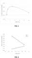
- the hydrogen capacity of a hopcalite catalyst increases as the Cu/Mn molar ratio increases from about 0.5 and peaks as the Cu/Mn ratio reaches about 3.
- the molar ratio of copper to manganese in the first hopcalite catalyst is typically at least 0.6, or at least 0.7, or at least 0.8, or at least 0.9, or at least 1, or at least 1.1, or at least 1.2, or at least 1.5.
- the Inventors have also observed that the hydrogen capacity of a hopcalite catalyst having a Cu/Mn molar ratio greater than about 7, e.g., about 10, is less than that of a standard hopcalite catalyst. Therefore, there is typically a "sweet spot" in the Cu/Mn molar ratio in terms of hydrogen capacity.
- the molar ratio of copper to manganese in the first hopcalite catalyst is no more than 7, e.g., no more than 6 or no more than 5.
- the molar ratio of copper to manganese in the first hopcalite catalyst is in a range from 0.6 to 4, e.g., from 0.6 to 3 or from 1 to 4.
- the molar ratio of copper to manganese in the first hopcalite catalyst is in a range from 1 to 5, such as from 2 to 4, e.g., from 2.5 to 3.5.
- the Inventors expect that such hopcalite catalysts would be particularly suitable for catalyst layers where the focus is on removing trace hydrogen rather than trace carbon monoxide.
- the capacity of hopcalite for carbon monoxide tends to reduce as the Cu/Mn molar ratio increases beyond about 0.5. Therefore, in other embodiments, the molar ratio of copper to manganese in the first hopcalite catalyst is in a range from 0.6 to 1.2, e.g., from 0.8 to 1.2 or from 0.9 to 1.2 or from 1 to 1.2.
- the Inventors have observed that a hopcalite catalyst having a Cu/Mn molar ratio within these ranges, and particularly a hopcalite catalyst having a Cu/Mn molar ratio of 1, tends to strike an acceptable balance between gain in hydrogen capacity and loss of carbon monoxide capacity. The Inventors expect that such hopcalite catalysts would be particularly suitable for catalysts layers where the focus is on removing both trace hydrogen and trace carbon dioxide.
- the dry gas may be passed through one or more layers of a first hopcalite catalyst to remove both hydrogen and carbon monoxide impurities.
- the Cu/Mn molar ratio of the first hopcalite catalyst may be in the range from 0.6 to 3, such as from 0.6 to 1.2, e.g., from 0.8 to 1.2 or from 0.9 to 1.2.
- Another suitable range for the Cu/Mn molar ratio may be from 1 to 3, such as from 1 to 1.2.
- Trace hydrogen and trace carbon monoxide are removed in separate layers of hopcalite. Trace carbon monoxide is removed by passing the dry gas across at least one layer of a standard hopcalite catalyst or a mixture of a standard hopcalite catalyst and a high Cu hopcalite catalyst, and trace hydrogen is removed by passing the dry gas across at least one layer of a high Cu hopcalite catalyst.
- the Cu/Mn molar ratio of the high Cu hopcalite catalyst used to remove trace carbon monoxide may be in the range from 0.6 to 3, such as from 0.6 to 1.2, e.g., from 0.8 to 1.2 or from 0.9 to 1.2 or from 1 to 1.2. Additionally or alternatively, the Cu/Mn molar ratio of the high Cu hopcalite catalyst used to remove trace hydrogen may be in the range from 0.6 to 4, such as from 2 to 4, e.g., from 2.5 to 3.5.
- a layer of carbon dioxide adsorbent material may be provided between adjacent layers of hopcalite catalyst.
- the Inventors have observed that the high Cu hopcalite catalyst are less sensitive to the presence of carbon dioxide in the dry gas than a standard hopcalite catalyst.
- the feed gas to the catalyst layer must contain no more than 10 ppmv carbon dioxide in order to enable hydrogen removal by adsorption on the hopcalite.
- both hydrogen and carbon monoxide can still be removed effectively in the presence of 400 ppmv carbon dioxide.
- the first hopcalite catalyst usually has a surface area of less than 280 m 2 /g, such as no more than 250 m 2 /g, e.g., from 150 m 2 /g to 250 m 2 /g, or such as no more than 200 m 2 /g, e.g. from 100 m 2 /g to 200 m 2 /g.
- the total pore volume and/or average pore size may also contribute to the improved performance of the high Cu hopcalite catalyst in the presence of carbon dioxide.
- the first hopcalite catalyst typically has a total pore volume of less than 0.4 cm 3 /g. In preferred embodiments, the first hopcalite catalyst has a total pore volume in a range from 0.1 cm 3 /g to 0.3 cm 3 /g.
- an advantage of preferred embodiments of the present invention is that the process can accommodate higher concentrations of hydrogen and carbon monoxide impurities in the dry gas than the concentrations disclosed in EP2789376A .
- the dry gas of the present process typically contains up to 40 ppmv hydrogen, e.g., from more than 20 ppmv to 40 ppmv. Additionally or alternatively, the dry gas may contain up to 50 ppmv carbon monoxide.
- the present process can accommodate a greater amount of carbon dioxide in the dry gas.
- the process can accommodate up to 900 ppmv carbon dioxide, e.g. up to 600 ppmv or up to 500 ppmv carbon dioxide, in the dry gas.
- the process will usually tolerate carbon dioxide in the dry gas in an amount of more than 10 ppmv to 600 ppmv, such as from 20 ppmv to 600 ppmv, e.g. from 50 ppmv to 500 ppmv.
- EP2789376A exemplifies regenerating a layer of standard hopcalite catalyst at a temperature of 180°C.
- the high Cu hopcalite catalyst used in the present invention may be regenerated at a temperature below 180°C, for example no more than 150°C or no more than 100°C, e.g. from 50°C to 100°C or 70°C or 60°C.
- the lower regeneration temperature extends the range of air pre-purification cycles in which hopcalite can be used to remove both carbon monoxide and hydrogen.
- the present process may be incorporated within a temperature swing adsorption (TSA) cycle, a thermal pressure swing adsorption (TPSA) cycle or a thermally enhanced pressure swing adsorption (TEPSA) cycle which have decreasing regeneration temperature levels of about 200°C, about 180°C and about 60°C respectively.
- TSA temperature swing adsorption
- TPSA thermal pressure swing adsorption
- TEPSA thermally enhanced pressure swing adsorption
- the high Cu hopcalite catalyst would be significantly less expensive than noble metal catalyst in either TEPSA or PSA.
- a further advantage of preferred embodiments of the present invention is that preferred feed temperatures may be lower.
- the dry gas in EP2789376A is most preferably at a temperature from 15°C to 30°C.
- the dry gas may be at a temperature below 15°C down to 10°C.
- the dry gas is usually passed through the layer(s) of the first hopcalite catalyst at a pressure in a range from 3 bar to 45 bar (0.3 MPa to 4.5 MPa), typically from 3 bar to 30 bar (0.3 MPa to 3 MPa).
- the dry gas is passed through at least one layer of a second hopcalite catalyst upstream of first layer(s) of the first hopcalite catalyst, wherein the second hopcalite catalyst has a molar ratio of copper to manganese of no more than 0.55.
- the dry gas is typically passed through a layer of carbon dioxide adsorbent material downstream of the second hopcalite catalyst and upstream of the first hopcalite catalyst.
- a process for removing hydrogen from dry air comprising the hydrogen as an impurity, the process comprising passing the dry air at a pressure from 3 bar to 30 bar (0.3 MPa to 3 MPa) and at a temperature from about 0°C to about 60°C through at least one layer of a first hopcalite catalyst to produce dry air that is at least substantially free of hydrogen, wherein the first hopcalite catalyst has a molar ratio of copper to manganese in a range from 2 to 4.
- a process for removing hydrogen and carbon monoxide from dry air comprising the hydrogen and the carbon monoxide as impurities, the process comprising passing the dry air at a pressure from 3 bar to 30 bar (0.3 MPa to 3 MPa) and at a temperature from about 0°C to about 60°C through at least one layer of a first hopcalite catalyst to produce dry air that is at least substantially free of hydrogen and carbon monoxide, wherein the first hopcalite catalyst has a molar ratio of copper to manganese in a range from 0.6 to 1.2, e.g.
- an adsorption unit for removing water, carbon dioxide, hydrogen and carbon monoxide impurities from a gas comprising the impurities, the unit comprising an adsorbent bed having a feed end and a product end opposite the feed end, the adsorbent bed consisting of:
- the adsorbent bed may consist of (in "on stream” order):
- the hopcalite catalysts are typically the sole catalysts present for removing hydrogen.
- one advantage of preferred embodiments of the present invention is that hydrogen impurity is removed from the dry gas in the absence of a noble metal catalyst.
- a process for removing hydrogen from a dry gas comprising hydrogen as an impurity comprising passing the dry gas at a temperature from about 0°C to about 60°C through at least one layer of a first hopcalite catalyst to produce product gas that is at least substantially free of hydrogen, wherein said first hopcalite catalyst has a molar ratio of copper to manganese of more than 0.55 to 7, and wherein said dry gas is passed through at least one layer of a second hopcalite catalyst upstream of said layer(s) of said first hopcalite catalyst, wherein said second hopcalite catalyst has a molar ratio of copper to manganese of no more than 0.55..
- the hydrogen impurity, or trace hydrogen is typically removed from the dry gas in the absence of a noble metal catalyst.
- Hopcalite is typically present as the sole catalyst for removing trace hydrogen.
- the hopcalite catalyst is either high Cu hopcalite catalyst alone or a combination of high Cu hopcalite catalyst and standard hopcalite catalyst. Where combinations of different hopcalites are used, the different hopcalite catalysts are preferably in different layers from each other although one or more layers of mixed hopcalites are possible.
- the first hopcalite catalyst typically comprises from about 5 wt % to about 40 wt % manganese and from about 25 wt % to about 70 wt % copper in embodiments having a molar ratio of copper to manganese in the range from 0.6 to 7, and from about 15 wt % to about 40 wt % manganese and from about 25 wt % to about 60 wt % copper in embodiments having a molar ratio of copper to manganese in the range from 0.6 to 3.
- "wt %” is based on the total metal content of the catalyst measured by X-ray fluorescence, or XRF.
- the first hopcalite catalyst may consist essentially of oxides of manganese and copper.
- the catalyst comprises at least one (and preferably each) additional metal species selected from the group consisting of potassium, sodium, calcium, silicon, and aluminium.
- the additional metal species are typically present in total amount from about 2 wt % to about 10 wt %.
- the first hopcalite catalyst may have any suitable form but is usually in the form of pellets such as extruded pellets.
- the catalyst pellets typically have a mean average diameter in a range from about 1 mm to about 6 mm, such as from about 2.5 mm to 3.5 mm, and a mean average length in a range from about 1 mm to about 10 mm, such as from about 3 mm to about 7 mm.
- the dry gas typically has a residence time within the layer of high Cu hopcalite of at least 0.1 s, such as at least 0.2 s, e.g. at least 0.3 s.
- the residence time of the dry gas within the layer of high Cu hopcalite catalyst is preferably no more than about 5 s, such as no more than 4 s, e.g. no more than 3 s or no more than 2 s.
- the residence time may be from 0.1 s to 5 s, from 0.2 s to 4 s or from 0.3 s to 3 s.
- the residence time is usually shorter than required in EP2789376A due to the greater reactivity of the catalyst to hydrogen.
- “residence time” is defined as the volume of the catalyst layer divided by the volumetric feed gas flow rate evaluated at the temperature and pressure within the catalyst layer.
- the hydrogen content of the dry gas is typically no more than 40 ppmv.
- the hydrogen content in the dry gas may be as low as 0.1 ppmv, e.g. from 0.1 ppmv to 40 ppmv, e.g. from more than 20 ppmv to 40 ppmv.
- the carbon monoxide content of the dry gas is typically no more than 50 ppmv, and usually from 0.5 ppmv to 20 ppmv.
- the dry gas typically contains no more than 10 ppmv, usually no more than 1 ppmv and typically no more than 0.5 ppmv, water.
- the catalyst comprises a mixture of metal oxides
- the catalyst itself may provide the oxygen required to oxide carbon monoxide and/or hydrogen.
- carbon monoxide would be oxidised to carbon dioxide according to the following reaction mechanism: CO + MnO 2 ⁇ CO 2 + MnO
- oxygen gas may be present in the dry gas and, if so, would be available as the oxidant for the oxidation reactions.
- Oxygen may be present in an amount from about 1 mol. % to about 99.9 mol. %.
- the dry gas is oxygen containing for example up to 1 mol. % hydrogen as an impurity.
- the dry gas may comprise at least one other gaseous component such as nitrogen and/or one or more noble gases.
- oxygen may be present in an amount from about 1 mol. % to about 50 mol. %.
- the dry gas is air.
- the process may be carried out at any suitable pressure, for example at atmospheric pressure or 1 bar (0.1 MPa).
- the effect of increasing the pressure of the gas is to increase the partial pressure of the impurity being removed. Since adsorption capacity increases as partial pressure increases, operation of the process at higher pressures enhances the adsorptive capacity of the bed, thereby enabling a reduction in size of the bed.
- the process is therefore preferably operated at an elevated pressure of more than 1 bar (0.1 MPa) and usually less than 50 bar (5 MPa), e.g. from 3 bar to 25 bar (0.3 to 2.5 MPa).
- pressures given in metric units are calculated on an absolute basis.
- the dry gas is typically at a temperature from about 0°C to about 60°C, e.g. from about 5°C to about 50°C, such as from about 15°C to about 30°C, i.e. about ambient temperature, or from about 10°C to about 15°C.
- the product gas typically comprises no more than about 1 ppmv, e.g. no more than about 500 ppb, preferably no more than about 50 ppb and more preferably no more than about 10 ppb, carbon monoxide.
- the product gas typically comprises no more than about 1 ppmv, e.g. no more than about 500 ppb, preferably no more than about 50 ppb and more preferably no more than about 10 ppb, hydrogen.
- the dry gas may be formed by passing feed gas through at least one adsorbent layer to remove water and carbon dioxide.
- the adsorbent layer may comprise either alumina or potassium carbonate-promoted alumina alone (to remove both water and carbon dioxide), or a first layer of alumina or potassium carbonate-promoted alumina (to remove primarily water) together with a second layer of zeolite (e.g., 13X) to remove carbon dioxide.
- carbon dioxide adsorbent material e.g., 13X zeolite
- the catalyst layer is regenerated.
- the catalyst must be regenerated thermally in order to restore the chemisorptive capacity of the catalyst towards hydrogen.
- the catalyst layer is preferably regenerated by passing a regeneration gas at a temperature in a range from 60°C to 200°C, or from 60°C to less than 180°C, through the catalyst layer.
- the regeneration gas is usually passed through the catalyst layer for not more than 6 h and usually not more than 4 h.
- the catalyst layer is usually regenerated by passing a regeneration gas at a temperature of at least 60°C through the catalyst layer for at least 25 min. More preferably, the regeneration gas is passed at a temperature of at least 150°C for at least 2 h.
- the regeneration gas may comprise a waste gas from a cryogenic distillation process.
- the regeneration gas comprises a portion of the product gas.
- the regeneration gas comprises oxygen and is at a temperature at least as high as the temperature of the product gas when used as regeneration gas, to supply oxygen to the catalyst surface.
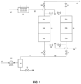
- a stream 10 of air is compressed to an elevated pressure from 3 bar to 25 bar (0.3 to 2.5 MPa) in a main air compressor 12.
- the compressed stream is cooled in cooler 14 and a portion of the water in the air stream is condensed and separated from the gas and discharged through valve 16.
- a stream 17 of cooled, partially dried air at a temperature of 5 to 60°C is then passed to vessel 24 via valve 20.
- Vessels 24 and 26 are each packed with identical layers of adsorbent and catalyst.
- the feed air passes to a first layer (24a or 26a) of water adsorbent which dries the feed air.
- This layer can also remove a portion of the carbon dioxide in the feed gas due to co-adsorption of carbon dioxide with water.
- This layer typically consists of alumina, base-promoted alumina, or silica gel.
- This layer consists of a zeolitic adsorbent such as NaX, NaLSX or CaX.
- the dried, carbon dioxide-free air is then passed to a layer of high copper hopcalite (24c or 26c) where carbon monoxide is oxidized to carbon dioxide and hydrogen is chemisorbed and possibly reacted to form water.
- the resultant trace level of carbon dioxide and any water produced from these reactions are adsorbed onto the hopcalite.
- Air flow continues for a predetermined period of time, and the various layers are sized so that water, carbon dioxide, carbon monoxide, and hydrogen are retained in the bed and a stream of purified air (containing no more than 0.5 ppmv water, no more than 1 ppmv carbon dioxide, no more than 500 ppb carbon monoxide, and no more than 500 ppb hydrogen) exits the vessel 24.
- This purified air passes through valve 36 and is directed as stream 40 to a cryogenic distillation system (not shown) where UHP nitrogen is produced.
- Vessel 26 is subjected to thermal regeneration steps while vessel 24 is processing the feed stream. Regeneration desorbs water from layer 26a and carbon dioxide from layer 26b. In addition, thermal regeneration of the hopcalite catalyst in layer 26c restores the hydrogen chemisorption capacity of the material. Thermal regeneration may be conducted at a temperature of at least 60 °C, more preferably at least 150°C, for example at about 180°C, in order to drive chemisorbed hydrogen/water from the catalyst.
- Regeneration is conducted by heating a stream 47 of dry, carbon dioxide-free purge gas through heater 52 to produce a stream 48 of warm purge gas which is fed to vessel 26 via manifold 42 and valve 46.
- the purge gas can be taken as a portion of the product gas 40 or from waste gas from the cryogenic distillation unit.
- the warm purge gas passes through layers 26c, 26b, and 26a of vessel 26, thereby regenerating the catalyst and adsorbent.
- the effluent gas from bed 26 passes through valve 32 and manifold 28 before being vented from the process as stream 34. Once the layers have been sufficiently warmed and regenerated, the bed is cooled by turning off or by-passing heater 52 so that cool purge gas at a temperature from 10 to 60°C flows through the bed.
- the feed and regeneration steps are conducted as described for a predetermined period of time, after which the functions of vessels 24 and 26 are switched so vessel 26 comes “on-line” and accepts feed gas, and vessel 24 goes “off-line” and is regenerated.
- the vessels alternate between feed and regeneration to maintain constant production of purified air.
- the regeneration step can be conducted in different ways to help improve the efficiency of the process.
- the bed undergoing regeneration can first be depressurized to essentially atmospheric pressure via valves 30 or 32 and vent 34, and the heating and cooling step can be conducted at the lower pressure.
- the warm purge fluid can be fed to the vessel until the entire vessel reaches the higher regeneration temperature, and then the cooling gas flow can be started. This is known in the art as a TSA cycle. However, in preferred embodiments, only a portion of the warm purge gas needed to heat the entire contents of the vessel is used before starting the cooling step.
- Fig. 1 illustrates a two-bed TSA process, but systems utilizing three or more vessels are also possible.
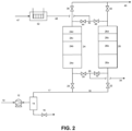
- FIG. 2 A second reference example is illustrated in Fig. 2 where an additional adsorbent layer 24d, 26d is added after the catalyst layer 24c, 26c.
- the hopcalite catalyst has a significant capacity for carbon dioxide adsorption, the capacity is finite. It is therefore possible that breakthrough of carbon dioxide formed from carbon monoxide oxidation in the catalyst would limit the time during which the system illustrated in Fig. 1 is on-line. In that case, a longer on-line time can be achieved by adding a short layer 24d, 26d of carbon dioxide adsorbent after the hopcalite layer. This layer would consist of a zeolitic adsorbent such as 13X, CaX, or NaLSX.
- compositions made in this manner had lower surface areas than commercially supplied hopcalite, with surface areas less than 100 m 2 /g.
- Particle sizes from each composition were determined to be similar from powder X-ray diffraction line broadening of diffraction peaks. hydrogen uptake differences were therefore attributed to Cu/Mn differences, and not to variation in particle size or surface area.
- Hydrogen (H 2 ) uptake capacity on synthesized hopcalites catalysts were measured on a commercial gas isotherm measurement device (HPA 300 Adsorption Unit, VTI Corp.). Two grams were used for each hopcalite powder. The powders were vacuum activated at 200°C overnight, then held at 30°C for duration of hydrogen uptake measurement. Hydrogen was dosed at increasing partial pressures, with 5.5 seconds of equilibration time, to simulate contact times in packed column breakthrough experiments. After 5.5 seconds, the uptake capacity was recorded by the instrument, and the next incremental pressure of hydrogen was dosed.
- HPA 300 Adsorption Unit VTI Corp.
- Feed gas was passed through a reactor vessel packed with hopcalite, and the gas effluent concentration was monitored to demonstrate the performance differences of standard vs. high Cu hopcalite.
- the reactor vessel was fitted with sample taps along the length of the reactor.
- the catalyst was regenerated by heating to 200°C (standard hopcalite catalyst) or 70°C (high Cu hopcalite catalyst) under a flow of air for at least 4 h, then allowed to cool to room temperature.
- Dry air was pre-treated (to remove carbon dioxide and trace levels of hydrogen and carbon monoxide) and used as feed gas, and dilute mixtures in nitrogen (spike gases) of carbon monoxide, hydrogen and/or carbon dioxide were blended with the feed air to achieve the desired feed gas compositions. Varying hydrogen, carbon monoxide, and carbon dioxide concentrations in air are described below in Reference Examples 2A through 2F.
- Column pressure was maintained at 130 psig (0.9 MPa), and the reactor temperature was controlled with external coils circulating chilled or heated water to a temperature from 14°C, 25°C or 40°C.
- the feed gas flow rate was 3.5 scfm (1.7 ⁇ 10 -3 m 3 /s).
- a feed step was initiated by starting the desired air and spike gas flows to the column and sampling the gas at the various sample ports with a residual gas analyser (Peak Performer 1, Peak Laboratories) to detect hydrogen and carbon monoxide. Analysers were also available for measuring the effluent gas carbon dioxide content (Teledyne GFC7000TU) and dew point (Meeco Aquamatic +). Carbon dioxide could be seen to breakthrough prior to hydrogen on the high Cu hopcalite under some conditions, but water was never observed in the effluent. Sampling at the multiple sample ports during a run allowed evaluation of the breakthrough performance for various gas residence times, where the residence time is defined as the volume of the catalyst layer from the feed end to the chosen sample port divided by the volumetric feed gas flow rate evaluated at the reactor temperature and pressure.
- Breakthrough curves were used to calculate relative residence time requirements shown in Table 1 for varying feed conditions in Reference Examples 2A through 2E.
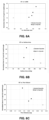
- Results of Reference Example 2F are shown in Fig. 7 .
- Results of Reference Example 2C at varying feed gas temperatures, and extrapolated to lower temperatures, are shown in Figure 10 .
- Reference Example 2A 2 ppmv hydrogen Reference Example 2B 10 ppmv carbon monoxide
- Reference Example 2C 2 ppmv hydrogen & 10 ppmv carbon monoxide
- Optimal ranges of varying properties of the hopcalite material for hydrogen capacity have been determined with breakthrough tests, as described in Reference Example 2C, and as shown in Fig 6A (Cu/Mn molar ratio), Fig. 6B (surface area) and Fig. 6C (pore volume) on varying commercially supplied hopcalite materials.
- the surface areas and pore volumes were determined by N 2 isotherms at 77K (Micrometrics 3Flex), and Cu/Mn ratios determined by X-ray fluorescence spectroscopy (Axios WDXRF Spectrometer).
- Reference Example 2D 2 ppmv hydrogen & 400 ppmv carbon dioxide
- the regeneration step prior to the feed step, was conducted at only 70°C instead of 200°C.
- a feed step was then run at same conditions as described in Reference Example 2C, while measuring hydrogen concentration exiting the gas layer at 3.5 sec residence time.
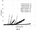
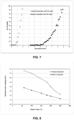
- Figs. 4 & 5 show that the high Cu hopcalite catalyst has significantly higher hydrogen capacity than the standard hopcalite catalyst, enabling the use of high Cu hopcalite for hydrogen and carbon monoxide removal in gas purification cycles utilizing low temperature regeneration (as described in, but not limited to, US5614000 which discloses TEPSA purification prior to cryogenic distillation).
- Regeneration temperatures included 60°C, 100°C, 150°C, 180°C, 200°C, 220°C and 250°C.
- the residual water (wt %) was calculated using the following formula: 100 ⁇ weight loss between regeneration temperature and 400 ° C sample weight after 400 ° C dwell
- the high Cu hopcalite catalyst had less residual water than the standard hopcalite catalyst at any given regeneration temperature. It is known in the art that adsorbed water deactivates the catalyst. Therefore, these results suggest that the high Cu hopcalite catalyst can be regenerated at lower temperatures than the standard hopcalite catalyst
- An air pre-purification adsorption unit can be designed using different adsorbents to remove water, carbon dioxide, hydrogen, and carbon monoxide.
- An air feed at a pressure of 130 psig and a temperature of 25°C can contain 1900 ppmv water, 400 ppmv carbon dioxide, 2 ppmv hydrogen and 10 ppmv carbon monoxide. As shown in Fig. 9 , many possible layering configurations can accomplish the removal of these impurities.
- Fig. 11 The arrangement exemplified in Fig. 1 of EP2789376A (where standard hopcalite catalyst (Carulite 300) was used as a single layer at the product end of the bed for removal of hydrogen and carbon monoxide removal) is illustrated in Fig. 11 in comparison with a corresponding arrangement according to a reference example of the present invention.
- standard hopcalite catalyst Carulite 300
- Alumina and 13X can be used in either configuration to reduce water and carbon dioxide respectively, below 1 ppmv in the product gas, i.e., purified air.
- Such an adsorption unit could be run in a cyclic fashion, where purge gas, taken from the downstream cryogenic distillation process, can be used to regenerate the materials in the adsorption unit at ambient pressure and a temperature of 200°C, before cooling the adsorption bed and re-pressurizing the unit back to feed conditions to begin another on-stream cycle.
- the feed air can also be chilled by a device to a temperature in the range from 10°C to 15°C to enable further advantages arising from the use of high Cu hopcalite catalyst.
- the overall size of the adsorption unit can be reduced as the colder air will contain less water vapor, and accordingly less alumina will be required. Further, alumina and 13X will have increased adsorption capacity for water and carbon dioxide at lower temperature.
- the hopcalite catalyst requirement will increase at colder temperatures, the increase in requirement regarding the high Cu hopcalite catalyst will be less than that for the standard hopcalite catalyst, as illustrated in Fig. 11 .
- a layer of water adsorption material e.g., alumina
- a layer of water adsorption material at the front end of the bed is typically the most practical arrangement.
- a first layer of hopcalite catalyst can be used next for removal of trace carbon monoxide.
- This layer can be standard hopcalite catalyst or high Cu hopcalite catalyst. If high Cu hopcalite catalyst is used, a reasonable amount of residence time can be used to remove at least substantially all trace hydrogen as well (see Table 1).
- An advantage of high Cu hopcalite catalyst in this location is being closer to the temperature rise from water adsorption on alumina, where higher temperature improves capacity in the catalyst layer ( Fig 5 ). Standard hopcalite cannot be placed immediately after the alumina layer due to the sensitivity of the hopcalite to carbon dioxide (see EP2789376A ).
- Hopcalite catalysts with lower surface areas will have lower carbon dioxide capacity.
- the lower surface area of high Cu hopcalite catalyst necessitates the presence of a carbon monoxide oxidation layer upstream of a carbon dioxide removal layer.
- Low surface area hopcalite cannot be the final layer if carbon monoxide is still present in the feed gas, otherwise carbon dioxide made from carbon monoxide oxidation will end up in the product stream. Therefore, a layer of carbon dioxide adsorbent material (e.g ., 13X) is typically next.
- a second layer of high Cu hopcalite catalyst may be used as a final purification layer.
- a standard hopcalite catalyst must be placed after a layer to remove water and a layer to remove carbon dioxide as these impurities poison the hopcalite catalyst and dramatically reduce its effectiveness towards hydrogen and carbon dioxide oxidation.
- high Cu hopcalite catalyst is less sensitive to carbon dioxide.
- the Inventors attribute this insensitivity to (a) higher Cu/Mn ratio giving higher hydrogen activity, and (b) the relative lower surface area and higher CuO content decreasing affinity of the material for water, which would normally poison hopcalite activity.
- the carbon monoxide removal effectiveness is lower than standard hopcalite, one skilled in the art can design a front-end adsorption unit using less overall catalyst compared to simply using standard hopcalite (see Table 1).
- Table 1 provides details of relative required contact times, showing how high Cu hopcalite catalyst reduces the amount of residence time needed compared with standard hopcalite for varying impurities in the feed gas.
Claims (16)
- Procédé pour éliminer l'hydrogène d'un gaz sec comprenant de l'hydrogène en tant qu'impureté, ledit procédé comprenant le passage dudit gaz sec à une température d'environ 0 °C à environ 60 °C à travers au moins une couche d'un premier catalyseur hopcalite pour produire un produit gazeux qui est au moins sensiblement exempt d'hydrogène, dans lequel ledit premier catalyseur hopcalite présente un rapport molaire du cuivre au manganèse dans une plage de plus de 0,55 à 7, et dans lequel ledit gaz sec est amené à passer à travers au moins une couche d'un deuxième catalyseur hopcalite en amont de ladite (desdites) couche(s) dudit premier catalyseur hopcalite, dans lequel ledit deuxième catalyseur hopcalite présente un rapport molaire du cuivre au manganèse non supérieur à 0,55.
- Procédé selon la revendication 1, dans lequel ledit rapport molaire du cuivre au manganèse dans ledit premier catalyseur hopcalite est dans une plage de 0,8 à 7.
- Procédé selon la revendication 1, dans lequel ledit rapport molaire du cuivre au manganèse dans ledit premier catalyseur hopcalite est dans une plage de 0,6 à 4.
- Procédé selon la revendication 3, dans lequel ledit rapport molaire du cuivre au manganèse dans ledit premier catalyseur hopcalite est dans une plage de 0,6 à 1,2.
- Procédé selon la revendication 2 ou revendication 3, dans lequel ledit rapport molaire du cuivre au manganèse dans ledit premier catalyseur hopcalite est dans une plage de 2 à 4.
- Procédé selon l'une quelconque des revendications précédentes, dans lequel ledit premier catalyseur hopcalite présente une surface dans une plage de 100 m2/g à 200 m2/g.
- Procédé selon l'une quelconque des revendications précédentes, dans lequel ledit premier catalyseur hopcalite présente un volume des pores total dans une plage de 0,1 cm3/g à 0,3 cm3/g.
- Procédé selon l'une quelconque des revendications précédentes, dans lequel ladite impureté hydrogène est présente dans ledit gaz sec dans une quantité allant jusqu'à 40 ppmv.
- Procédé selon l'une quelconque des revendications précédentes, dans lequel ledit gaz sec comprend du dioxyde de carbone dans une quantité allant jusqu'à 900 ppmv.
- Procédé selon l'une quelconque des revendications précédentes, dans lequel ladite(lesdites) couche(s) dudit premier catalyseur hopcalite est/sont régénérées à une température non supérieure à 150 °C.
- Procédé selon la revendication 10, dans lequel ladite(lesdites) couche(s) dudit premier catalyseur hopcalite est/sont régénérées à une température de 50 °C à 100 °C.
- Procédé selon l'une quelconque des revendications précédentes, dans lequel la température dudit gaz sec est dans une plage de 10 °C à 15 °C.
- Procédé selon l'une quelconque des revendications précédentes, dans lequel ledit gaz sec est amené à passer à travers ladite(lesdites) couche(s) dudit premier catalyseur hopcalite à une pression dans une plage de 3 bar à 45 bar (0,3 MPa à 4,5 MPa).
- Procédé selon l'une quelconque des revendications précédentes, dans lequel ledit gaz sec est de l'air.
- Unité d'adsorption pour éliminer les impuretés eau, dioxyde de carbone, hydrogène et monoxyde de carbone d'un gaz comprenant lesdites impuretés, ladite unité comprenant un lit adsorbant présentant une extrémité d'alimentation et une extrémité de produit en aval de ladite extrémité d'alimentation, ledit lit adsorbant étant constitué de :une couche de matériau adsorbant l'eau prévue à l'extrémité d'alimentation du lit pour éliminer l'eau dudit gaz pour produire le gaz sec ;au moins une couche d'un premier catalyseur hopcalite présentant un rapport molaire du cuivre au manganèse dans une plage de plus de 0,55 à 7 pour éliminer l'impureté hydrogène dudit gaz sec pour produire un produit gazeux qui est sensiblement exempt d'hydrogène ;au moins une couche de matériau adsorbant le dioxyde de carbone pour éliminer le dioxyde de carbone dudit gaz sec ; etau moins une couche d'un deuxième catalyseur hopcalite en amont de ladite (desdites) couche(s) dudit premier catalyseur hopcalite pour éliminer le monoxyde de carbone dudit gaz sec, dans lequel ledit deuxième catalyseur hopcalite présente un rapport molaire du cuivre au manganèse non supérieur à 0,55.
- Unité d'adsorption selon la revendication 15 dans lequel le lit adsorbant est constitué (dans l'ordre « en service ») d'une couche d'un matériau adsorbant l'eau, d'une seule couche du deuxième catalyseur hopcalite, d'une seule couche d'un matériau adsorbant le dioxyde de carbone et d'une seule couche du premier catalyseur hopcalite.
Applications Claiming Priority (2)
| Application Number | Priority Date | Filing Date | Title |
|---|---|---|---|
| US17/083,435 US11173451B1 (en) | 2020-10-29 | 2020-10-29 | Removal of hydrogen impurity from gas streams |
| EP21204594.2A EP3991826A1 (fr) | 2020-10-29 | 2021-10-25 | Élimination d'impuretés d'hydrogène dans des flux gazeux |
Related Parent Applications (1)
| Application Number | Title | Priority Date | Filing Date |
|---|---|---|---|
| EP21204594.2A Division EP3991826A1 (fr) | 2020-10-29 | 2021-10-25 | Élimination d'impuretés d'hydrogène dans des flux gazeux |
Publications (2)
| Publication Number | Publication Date |
|---|---|
| EP4088807A1 EP4088807A1 (fr) | 2022-11-16 |
| EP4088807B1 true EP4088807B1 (fr) | 2024-04-03 |
Family
ID=78524045
Family Applications (3)
| Application Number | Title | Priority Date | Filing Date |
|---|---|---|---|
| EP21204594.2A Pending EP3991826A1 (fr) | 2020-10-29 | 2021-10-25 | Élimination d'impuretés d'hydrogène dans des flux gazeux |
| EP22174903.9A Active EP4088807B1 (fr) | 2020-10-29 | 2021-10-25 | Élimination d'impuretés d'hydrogène dans des flux gazeux |
| EP22174900.5A Pending EP4088806A1 (fr) | 2020-10-29 | 2021-10-25 | Élimination d'impuretés d'hydrogène dans des flux gazeux |
Family Applications Before (1)
| Application Number | Title | Priority Date | Filing Date |
|---|---|---|---|
| EP21204594.2A Pending EP3991826A1 (fr) | 2020-10-29 | 2021-10-25 | Élimination d'impuretés d'hydrogène dans des flux gazeux |
Family Applications After (1)
| Application Number | Title | Priority Date | Filing Date |
|---|---|---|---|
| EP22174900.5A Pending EP4088806A1 (fr) | 2020-10-29 | 2021-10-25 | Élimination d'impuretés d'hydrogène dans des flux gazeux |
Country Status (5)
| Country | Link |
|---|---|
| US (1) | US11173451B1 (fr) |
| EP (3) | EP3991826A1 (fr) |
| KR (1) | KR20220057442A (fr) |
| CN (1) | CN114425233A (fr) |
| TW (1) | TW202216275A (fr) |
Families Citing this family (4)
| Publication number | Priority date | Publication date | Assignee | Title |
|---|---|---|---|---|
| US11359859B2 (en) * | 2020-08-19 | 2022-06-14 | Praxair Technology, Inc. | System for pre-purification of a feed gas stream |
| US11666861B2 (en) | 2020-08-19 | 2023-06-06 | Ralph J. Mancini | Method and system for pre-purification of a feed gas stream |
| US11850553B2 (en) | 2020-08-19 | 2023-12-26 | Praxair Technology, Inc. | System for pre-purification of a feed gas stream |
| CN117567795B (zh) * | 2024-01-16 | 2024-04-02 | 派纳维森(苏州)电气科技有限公司 | 一种电线电缆用抑烟减毒杂化材料及其制备方法和应用 |
Family Cites Families (19)
| Publication number | Priority date | Publication date | Assignee | Title |
|---|---|---|---|---|
| US1345323A (en) | 1919-02-04 | 1920-06-29 | Joseph C W Frazer | Catalyst and process of making it |
| FR2541588B1 (fr) | 1983-02-28 | 1985-07-05 | Air Liquide | Recipient et installation d'epuration par adsorption |
| US4925631A (en) * | 1988-09-26 | 1990-05-15 | Figgie International, Inc. | Method of casting a hopcalite filter and cast ceramic fiber-hopcalite |
| US5202096A (en) | 1990-01-19 | 1993-04-13 | The Boc Group, Inc. | Apparatus for low temperature purification of gases |
| CN1027802C (zh) | 1990-01-19 | 1995-03-08 | 波克集团股份有限公司 | 一种从原料气流中去除杂质的方法 |
| US5232474A (en) | 1990-04-20 | 1993-08-03 | The Boc Group, Inc. | Pre-purification of air for separation |
| FR2661841B1 (fr) | 1990-05-09 | 1992-07-17 | Air Liquide | Procede et appareil d'epuration par adsorption d'air destine a etre distille. |
| US5614000A (en) | 1995-10-04 | 1997-03-25 | Air Products And Chemicals, Inc. | Purification of gases using solid adsorbents |
| US5855650A (en) | 1997-09-09 | 1999-01-05 | Air Products And Chemicals, Inc. | Purification of gases using solid adsorbents |
| US5914455A (en) | 1997-09-30 | 1999-06-22 | The Boc Group, Inc. | Air purification process |
| US5906675A (en) | 1997-09-30 | 1999-05-25 | The Boc Group, Inc. | Air purification process |
| JP2000247919A (ja) * | 1999-02-26 | 2000-09-12 | Japan Pionics Co Ltd | 弗化アルコールの気相処理方法及び気相精製方法 |
| US6511640B1 (en) | 2000-06-29 | 2003-01-28 | The Boc Group, Inc. | Purification of gases |
| US20030064014A1 (en) | 2001-08-03 | 2003-04-03 | Ravi Kumar | Purification of gases by pressure swing adsorption |
| JP4048108B2 (ja) * | 2002-12-26 | 2008-02-13 | 日本パイオニクス株式会社 | 有害ガスの浄化方法 |
| DE102007037796A1 (de) * | 2007-08-10 | 2009-02-12 | Süd-Chemie AG | Verfahren zur Entfernung von CO, H2 und/oder CH4 aus dem Anodenabgas einer Brennstoffzelle mit Mischoxidkatalysatoren umfassend Cu, Mn und gegebenenfalls mindestens ein Seltenerdmetall |
| JP5863819B2 (ja) * | 2010-11-18 | 2016-02-17 | クラリアント コーポレイション | 燃料電池のアノード排ガスからco、h2、及びch4を除去する方法並びにこれらのガスを除去するのに有用な触媒 |
| EP2662653A1 (fr) | 2012-05-08 | 2013-11-13 | Linde Aktiengesellschaft | Procédé et dispositif destinés à la production dýazote sans hydrogène |
| US8940263B2 (en) | 2013-04-10 | 2015-01-27 | Air Products And Chemicals, Inc. | Removal of hydrogen and carbon monoxide impurities from gas streams |
-
2020
- 2020-10-29 US US17/083,435 patent/US11173451B1/en active Active
-
2021
- 2021-10-25 EP EP21204594.2A patent/EP3991826A1/fr active Pending
- 2021-10-25 TW TW110139470A patent/TW202216275A/zh unknown
- 2021-10-25 KR KR1020210142767A patent/KR20220057442A/ko not_active Application Discontinuation
- 2021-10-25 EP EP22174903.9A patent/EP4088807B1/fr active Active
- 2021-10-25 EP EP22174900.5A patent/EP4088806A1/fr active Pending
- 2021-10-29 CN CN202111274995.7A patent/CN114425233A/zh active Pending
Also Published As
| Publication number | Publication date |
|---|---|
| CN114425233A (zh) | 2022-05-03 |
| TW202216275A (zh) | 2022-05-01 |
| EP3991826A1 (fr) | 2022-05-04 |
| US11173451B1 (en) | 2021-11-16 |
| EP4088807A1 (fr) | 2022-11-16 |
| EP4088806A1 (fr) | 2022-11-16 |
| KR20220057442A (ko) | 2022-05-09 |
Similar Documents
| Publication | Publication Date | Title |
|---|---|---|
| EP2789376B1 (fr) | Élimination d'impuretés d'hydrogène et de monoxyde de carbone de courants gazeux utilisant un catalyseur à base de cuivre et de manganèse | |
| EP4088807B1 (fr) | Élimination d'impuretés d'hydrogène dans des flux gazeux | |
| US6113869A (en) | Process for argon purification | |
| US6048509A (en) | Gas purifying process and gas purifying apparatus | |
| CA2420756C (fr) | Charbon active utilise comme adsorbant unique dans un systeme de production d'hydrogene a cycles rapides par adsorption modulee en pression (amp) | |
| US7524358B2 (en) | Production of high purity and ultra-high purity gas | |
| EP1697042B1 (fr) | Procede de purification d'un flux gazeux contamine par co 2 et un ou plusieurs hydrocarbures et/ou oxydes d'azote par adsorption sur un adsorbant zeolitique agrege | |
| CA2291388C (fr) | Epuration de gaz | |
| US6093379A (en) | Purification of gases | |
| US6660240B1 (en) | Gas processing agent and manufacturing method therefor, gas purification method, gas purifier and gas purification apparatus | |
| US20030064014A1 (en) | Purification of gases by pressure swing adsorption | |
| EP1060774A1 (fr) | Purification de gaz | |
| EP1005895A1 (fr) | Purification de gaz | |
| KR101190461B1 (ko) | 고순도 및 초-고순도 기체의 제조 |
Legal Events
| Date | Code | Title | Description |
|---|---|---|---|
| PUAI | Public reference made under article 153(3) epc to a published international application that has entered the european phase |
Free format text: ORIGINAL CODE: 0009012 |
|
| STAA | Information on the status of an ep patent application or granted ep patent |
Free format text: STATUS: REQUEST FOR EXAMINATION WAS MADE |
|
| 17P | Request for examination filed |
Effective date: 20220523 |
|
| AC | Divisional application: reference to earlier application |
Ref document number: 3991826 Country of ref document: EP Kind code of ref document: P |
|
| AK | Designated contracting states |
Kind code of ref document: A1 Designated state(s): AL AT BE BG CH CY CZ DE DK EE ES FI FR GB GR HR HU IE IS IT LI LT LU LV MC MK MT NL NO PL PT RO RS SE SI SK SM TR |
|
| STAA | Information on the status of an ep patent application or granted ep patent |
Free format text: STATUS: EXAMINATION IS IN PROGRESS |
|
| 17Q | First examination report despatched |
Effective date: 20230602 |
|
| GRAP | Despatch of communication of intention to grant a patent |
Free format text: ORIGINAL CODE: EPIDOSNIGR1 |
|
| STAA | Information on the status of an ep patent application or granted ep patent |
Free format text: STATUS: GRANT OF PATENT IS INTENDED |
|
| INTG | Intention to grant announced |
Effective date: 20240116 |
|
| GRAS | Grant fee paid |
Free format text: ORIGINAL CODE: EPIDOSNIGR3 |
|
| GRAA | (expected) grant |
Free format text: ORIGINAL CODE: 0009210 |
|
| STAA | Information on the status of an ep patent application or granted ep patent |
Free format text: STATUS: THE PATENT HAS BEEN GRANTED |
|
| P01 | Opt-out of the competence of the unified patent court (upc) registered |
Effective date: 20240206 |
|
| AC | Divisional application: reference to earlier application |
Ref document number: 3991826 Country of ref document: EP Kind code of ref document: P |
|
| AK | Designated contracting states |
Kind code of ref document: B1 Designated state(s): AL AT BE BG CH CY CZ DE DK EE ES FI FR GB GR HR HU IE IS IT LI LT LU LV MC MK MT NL NO PL PT RO RS SE SI SK SM TR |
|
| REG | Reference to a national code |
Ref country code: CH Ref legal event code: EP |
|
| REG | Reference to a national code |
Ref country code: DE Ref legal event code: R096 Ref document number: 602021011431 Country of ref document: DE |