EP4088604B1 - Schutzkleidung - Google Patents
Schutzkleidung Download PDFInfo
- Publication number
- EP4088604B1 EP4088604B1 EP22173275.3A EP22173275A EP4088604B1 EP 4088604 B1 EP4088604 B1 EP 4088604B1 EP 22173275 A EP22173275 A EP 22173275A EP 4088604 B1 EP4088604 B1 EP 4088604B1
- Authority
- EP
- European Patent Office
- Prior art keywords
- protective garment
- inflation device
- container
- garment
- coupling
- Prior art date
- Legal status (The legal status is an assumption and is not a legal conclusion. Google has not performed a legal analysis and makes no representation as to the accuracy of the status listed.)
- Active
Links
Images


Classifications
-
- A—HUMAN NECESSITIES
- A41—WEARING APPAREL
- A41D—OUTERWEAR; PROTECTIVE GARMENTS; ACCESSORIES
- A41D13/00—Professional, industrial or sporting protective garments, e.g. surgeons' gowns or garments protecting against blows or punches
- A41D13/015—Professional, industrial or sporting protective garments, e.g. surgeons' gowns or garments protecting against blows or punches with shock-absorbing means
- A41D13/018—Professional, industrial or sporting protective garments, e.g. surgeons' gowns or garments protecting against blows or punches with shock-absorbing means inflatable automatically
-
- A—HUMAN NECESSITIES
- A41—WEARING APPAREL
- A41D—OUTERWEAR; PROTECTIVE GARMENTS; ACCESSORIES
- A41D13/00—Professional, industrial or sporting protective garments, e.g. surgeons' gowns or garments protecting against blows or punches
- A41D13/02—Overalls, e.g. bodysuits or bib overalls
-
- A—HUMAN NECESSITIES
- A41—WEARING APPAREL
- A41D—OUTERWEAR; PROTECTIVE GARMENTS; ACCESSORIES
- A41D2400/00—Functions or special features of garments
- A41D2400/24—Reducing drag or turbulence in air or water
-
- A—HUMAN NECESSITIES
- A41—WEARING APPAREL
- A41D—OUTERWEAR; PROTECTIVE GARMENTS; ACCESSORIES
- A41D2600/00—Uses of garments specially adapted for specific purposes
- A41D2600/10—Uses of garments specially adapted for specific purposes for sport activities
- A41D2600/102—Motorcycling
Definitions
- the present invention relates in general to the sector of providing protection by means of an inflatable element for protecting a user from falls and/or impacts during use of a vehicle, preferably a two-wheeled vehicle. More particularly, the present disclosure relates to a protective garment, preferably for motorcycling, for example a motorcycle suit, containing an inflation device for inflating an inflatable element designed to protect a user in the event of falls and/or impacts of various types.
- a personal protection device which include inflatable elements.
- a personal protection device normally includes an inflatable element or inflatable bag, an inflation device, sensors for detecting the fall or the impact and at least one control unit for managing the activation of the inflation device in order to inflate the inflatable element.
- the inflatable element is placed in fluid communication with the inflation device, which is configured to inflate the inflatable element in the event of an impact or fall.
- such an inflation device is formed by a fluid source, such as a canister which contains pressurised gas and which is opened by means of a punch or a small explosion which is managed by means of an electric activation signal.
- a fluid source such as a canister which contains pressurised gas and which is opened by means of a punch or a small explosion which is managed by means of an electric activation signal.
- gas generator Any form of fluid source intended to determine the outflow of pressurised gas into an inflatable element is referred to in the continuation of the present disclosure by the term "gas generator”.
- EP2939555A1 discloses the preamble of claim 1, US20080235854A1 , US6298487B1 , DE19703805A1 and EP3704981A1
- the gas generator is arranged inside the inflatable element, for reasons of convenience, so as to facilitate the fluid connection with the inflatable element.
- the entire protection device is then associated with the protective garment, inside which it is integrally inserted.
- the inflatable element and the gas generator are housed together inside the protective garment, for example inside an internal pocket of the same protective garment, underneath an external protection layer.
- Such a garment although advantageous from many points of view, has a number of drawbacks.
- the protection device is arranged so that its components are in a zone or region of the protective garment which are difficult for the user to access, and this condition requires the user to perform many operations in order to change, if necessary, the inflatable element or other components.
- one of the drawbacks consists in the fact that, for example, in the event of an impact or fall and consequently activation of the inflation device intended to inflate the inflatable device, in order to be able to restore the garment to its working condition and continue to ensure the protection by the inflatable element, the protection device must be fully replaced before it can be used again.
- the problem underlying the invention described below is therefore that of providing a protective garment, for example a motorcycling suit, which allows a user to restore the protection device to its working condition in a simplified manner, for example following initial inflation, and/or which is able to provide further advantages.
- the present invention is based on the recognition by the inventor that it is possible to incorporate a gas generator inside a special container so as to form a single body, which results in simple and safe handling by the user, and that the single body formed by the gas generator and the container may be easily coupled and uncoupled together with/from the inflatable element by means of a removable coupling device.
- the single body formed by the gas generator and container, which is in fact an inflation device, inside the aerodynamic hump present in the protective garments, in particular in motorcycle suits, for example inside a housing cavity.
- the single body formed by the gas generator and container, which is in fact an inflation device
- the aerodynamic hump present in the protective garments, in particular in motorcycle suits, for example inside a housing cavity.
- the aerodynamic hump from the inside of the protective garment, for example via a lining, so that access to the inflation device by the user is simplified.
- the access to the aerodynamic hump therefore allows a user to disconnect and reconnect easily the inflation device from/to the inflatable element, owing to the removable coupling device, in such a way as to allow rapid replacement of the gas generator, while the inflatable element may be configured to be used again for several successive inflation operations, without having to be replaced. It follows that a condition for removal of said inflation device corresponds to a condition for access to the aerodynamic hump from the internal surface of said garment.
- the main advantage of the invention consists in having a protective garment, for example a motorcycle suit, which contains the inflatable element inside it and in which the aerodynamic hump of the garment accommodates the inflation device inside the housing cavity so that it can be handled independently of the inflatable element, in such a way that the inflation device is easily accessible for a user by means of access to the aerodynamic hump, preferably from the inside of the garment.
- a protective garment for example a motorcycle suit, which contains the inflatable element inside it and in which the aerodynamic hump of the garment accommodates the inflation device inside the housing cavity so that it can be handled independently of the inflatable element, in such a way that the inflation device is easily accessible for a user by means of access to the aerodynamic hump, preferably from the inside of the garment.
- the inflation device needs to be replaced, a user may easily access the housing cavity of the aerodynamic cage by means of, for example, an internal lining and disconnect the inflatable element, being then able to connect it up again easily once the gas generator has been replaced.
- the protective garment for example a motorcycle suit, includes a support plate arranged inside the housing cavity and configured to support the inflation device and, if necessary, other components.
- the support plate preferably has a mechanical coupling component for allowing mechanical coupling with the inflation device, for example consisting of a clip-action coupling. Mechanical coupling is performed preferably together with the gas generator container.
- the housing cavity of the aerodynamic hump houses a support plate able to be connected to the inflation device by means of a mechanical coupling component.
- the mechanical coupling component is positioned in a coupling portion of the support plate.
- the mechanical coupling component may be clip or more than one clip for example with a C shape and elastic behaviour, which receives between the arms of the C the container of the inflation device.
- Gripping elements for example in the form of a ribbon or strip, may be provided, being connected to the container, in order to facilitate removal of the inflation device.
- the housing cavity of the aerodynamic hump also houses the electronic control unit, which has the function of controlling activation of the personal protection device and therefore inflation of the inflatable element by the gas generator.
- the control unit may be arranged on the support plate, for example alongside the inflation device, and may be connected to the support plate in a fixed manner, for example by means of screws.
- the garment includes a container or reservoir for drinkable liquids, referred to as "drinking bottle", which is arranged inside the housing cavity.
- the housing cavity of the aerodynamic hump also houses a liquids container.
- the liquids container is configured to occupy inside the housing cavity the space around the inflation device.
- the liquids container has an arc shape, or a curved shape along an arc trajectory, which defines a concavity.
- the empty zone defined by the concavity of said arc shape may accommodate the inflation device.
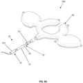
- the embodiment of the liquids container described above allows the container to be inserted inside the housing cavity by means of a rotational movement about the inflation device, wherein the liquids container passes through a receiving cavity of the support plate.
- This allows the container to be extracted and inserted back inside the aerodynamic hump, in order to fill it and/or empty it, without necessarily having to remove or displace the other components contained inside the housing cavity.
- the liquids container may be inserted inside the housing cavity of the aerodynamic hump by means of rotation about an axis which coincides with the longitudinal axis of the inflation device, when the latter is already positioned on the support plate and is located inside the housing cavity, passing through a receiving cavity of the support plate.
- each embodiment may have one or more of the advantages listed above; in any case it is nevertheless not necessary that each embodiment should have simultaneously all the advantages listed.
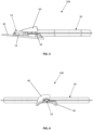
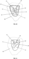
- the reference number 1000 indicates a protective garment such as a motorcycle suit, containing the personal protection device 100 according to an embodiment of the present invention and an aerodynamic hump 70.
- aerodynamic hump is understood as meaning a component - known in the motorcycling sector - which is shaped in the manner of a protuberance and used in the high part of the back with an aerodynamic function since it stabilizes a rider at high speeds.
- the aerodynamic hump 70 may be made with any form known to the person skilled in the art.
- the aerodynamic hump defines a cavity 71 which is accessible for a user, as will be explained below.
- the personal protection device 100 includes an inflatable element 50 which is configured to assume a deflated condition and an inflated condition and which is inflated when necessary, for example in the event of danger or an impact, or a fall.
- inflatable element is understood as meaning any body, member, device (also formed by several units) which may be inflated if necessary between the deflated condition and the inflated condition.
- the inflatable element may be realized using any technology known to the person skilled in the art.
- the personal protection device 100 further comprises an inflation device 10 able to inflate the inflatable element 50 and an electronic control unit 42.
- the inflation device 10 inflates the inflatable element 50, under the control of the electronic unit 42 which is in turn operatively connected to impact detection sensors.
- the protection device 100 is adapted to cooperate with special activation means (normally consisting of the aforementioned control unit and sensors) which are operatively connected for example to the inflation device.
- the activation modes although being an aspect of particular importance for effective operation of the device, will not be further described in greater detail since they are methods which are essentially already known to a person skilled in the art of protection of an individual from sudden impacts.
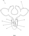
- the protective garment 1000 further includes a support plate 30 and a container or reservoir for drinkable liquids, referred to hereinbelow as "drinking bottle 60".
- the inflatable element 50 is intended to protect the upper zone of the torso of a user wearing the protective garment 1000.
- the inflation device 10, the support plate 30, the control unit 42 and the drinking bottle 60 are positioned inside the housing cavity 71 of the aerodynamic hump 70 of the protective garment 1000.
- the garment 1000 comprises an access zone 15 which allows a user wearing the suit 1000 to access the housing cavity 71 from the inside 80 of the said suit.
- the access zone 15 is identified for example by a zip 20 or other opening zip fastener, formed on a lining of the garment 1000.
- the electronic unit 42 is located preferably on one side of the inflation device in order to optimize the space inside the housing cavity 71.
- the access zone 15 is located in the vicinity of the aerodynamic hump 70.
- the access zone 15 is located on an inner surface or inner side 80 of the housing cavity 71.
- the inner side 80 is a side facing the zone which accommodates the body of a user when the protective garment 1000 is worn. In other words, it consists of a side facing a hidden zone of the protective garment 100 which is not visible when the garment is closed or worn.
- the access zone 15 may be configured to open or close in a simple manner the access to the housing cavity 71 by a user of the garment 1000, for example by means of a zip fastener or zip 20 associated with a lining of the garment 1000.
- the access zone 15 allows a user wearing the garment 1000 to access easily the housing cavity 71 of the aerodynamic hump from the inside of the protective garment 1000, so as to handle the components inserted inside the said cavity. for example in order to extract or reinsert them.
- the inflation device 10 includes at least one gas generator 12 and a container 14 for containing said at least one gas generator 12.
- the gas generator 12 is provided with a region 16 intended for the passage of gas, namely a region which, when the gas generator 12 is activated, allows gas to pass towards the inflatable element 50.
- the gas generator 12 may be provided, as is known, with a shut-off valve, not visible in the drawings.
- the gas generator 12 may be a canister containing compressed cold gas, such as helium.
- the gas generator 12 may be a gas generator of the pyrotechnic or hybrid type or of other types known in the state of the art.
- the container 14 and the at least one gas generator 12 form a structurally independent assembly configured to be handled as a single body with respect to said inflatable element 50.
- the inflation device 10 comprises a coupling component 18 configured to be removably coupled with a coupling counter-component 52 associated with said inflatable element 50.
- Such an inflation device 10 may be positioned on the support plate 30 to which it is coupled by means of a mechanical type coupling.
- the support plate 30 has a coupling portion 31 inside which the inflation device 10 may be housed.
- the coupling between the inflation device 10 and the support plate 30 is a mechanical type coupling which allows the two components to be easily disconnected and connected together again, for example consisting of a clip-action coupling.
- the clip has a C-shaped form with arms which are able to stably receive the container of the inflation device 10. The presence of the container allows a stable mechanical coupling to be obtained.
- a gripping element for example of a flexible nature, may be provided in order to facilitate removal of the container 14 with the gas generator 12 contained therein.
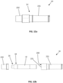
- the container 14 has the form of a tubular shell body defining an internal housing chamber 130 for housing the gas generator 12. In other words it consists of a body which may be easily gripped by a user.
- the container 14 includes two half-shells coupled together by means of conventional mechanical connection means so as to form said shell.
- the container 14 may comprise a main body 31, having a tubular shape, and a shell in the form of a closing cover 232, configured to close off the main body in the manner of a hood. It therefore consists of an end shell for closing off the main body 231 of the container 14.
- the container 14 may in turn comprise an end cover which closes off an end zone of the main body 231.
- the end cover may be a slider body configured to be able to slide in at least one insertion guide positioned in the proximity of the end zone of the main body 231.
- the main body 231 defines preferably a first open end 221, which may accommodate the coupling component 18 of the gas generator 12, and an opening in the vicinity of the end region, namely a second open end 222.
- the main body 231 and the closing cover 232 are, as mentioned, initially connected together to form one piece, as shown in Figure 12a .
- the container 14 is a closed single-piece body and connection means may be provided between the main body 231 and the closing cover 232.
- the connection means may be calibrated breakage bridge-pieces, also called breakable bridge-pieces. These calibrated breakage bridge-pieces may be broken by a user by means of relative rotation of the main body 231 and the closing cover 232 in opposite directions.
- a user who is holding the container 14 may rotate at least one of the main body 231 and the closing cover 232 in order to break the calibrated bridge-pieces so as to be able to separate the main body 231 and the closing cover 232, a shown in Figure 12b .
- the mechanical coupling between the inflation device 10 and the support plate 30 is therefore configured to allow easy connection and disconnection of the container 14 to/from the coupling portion 31 of the support plate 30.
- the coupling portion 31 has a housing with a form suitable for accommodating the tubular form of the container 14 and allowing the aforementioned clip-action coupling.
- the shell is made of rigid material.
- the rigid material facilitates the screw-type closure or generally mechanical coupling together with the coupling counter-component of the inflatable element 50.
- the support plate 30 is also made of rigid material, so as to favour the mechanical coupling between the support plate 30 and the inflation device 10.
- the coupling which is formed between the inflation device 10 and the inflatable element 50 is a mechanical coupling, for example a so-called quick-release coupling, quick-fit coupling, screw connection or a similar mechanical coupling which is known to the person skilled in the art. More preferably, it consists of a mechanical coupling of the male/female type.
- the inflation device therefore comprises either one of the male coupling component or a female coupling counter-component.
- the coupling component 18 is placed in the region 16 of the gas generator 12 intended for the outflow of the inflation gas.
- the coupling component 18, for example the aforementioned male or female component, may surround the region 16 intended for the gas outflow and be coupled with the other coupling component 52 which in turn may surround a gas intake opening of the inflatable element. In this way, as soon as the inflation device 10 is coupled together with the inflatable element 50, it is possible to establish fluid communication between the gas generator 12 and the inflatable element 50 when the gas generator 12 is activated.
- the gas generator 12 comprises said coupling component 18.
- the gas generator 12 is suitably modified to allow coupling.
- This solution ensures a greater pressure-tightness, considering the fact that the pressure comes from the gas generator.
- the gas generator 12 is shaped to comprise said coupling component as one piece or integrally.
- the coupling component 18 and the gas generator 12 therefore preferably form a single piece, namely they are components which are integrally made as a single body.
- the gas generator 12 is canister-shaped and, as mentioned above, said container 14 has a tubular form for accommodating the gas generator 12, and even more preferably the gas generator 12 is modified to include the coupling component 18 which, in the embodiment, is a male engaging component.
- the container 14 has a first open end 21, wherein said first open end 21 accommodates said coupling component 18 of the gas generator 12.
- the gas generator 12 may be inserted inside the container 14 and then, together with the latter, may be handled as a single body by a user.
- the gas generator 12 may then be coupled to the coupling counter-component 52 of the inflatable element 50 by means of direct gripping of the container 14.
- the container 14 therefore acts as a handle or gripping body for the gas generator 12.
- the container 14 may be advantageously configured to include a second open end 22.
- the second open end 22 may accommodate a component 40 for electrical connection with the control unit 42, so as to control activation of the gas generator 12.
- the container 14 may therefore be designed so as not to hinder, on the one hand, coupling with the inflatable element 50 and, on the other hand, connection with the control unit 42.
- the inflatable element 50 may project partially inside the aerodynamic hump 70 so as to allow connection together with the inflation device 10.
- a portion of the inflatable element, in particular the portion associated with the coupling counter-component 52 may be positioned partially inside the aerodynamic hump 70 so as to allow connection together of the coupling component 18, associated with the inflation device 10, and the coupling counter-component 52, associated with the inflatable element 50.
- control unit 42 is positioned in the vicinity of the inflation device 10 and inside the housing cavity 71 of the aerodynamic hump 70. Even more preferably, the control unit 42 is positioned on the support plate 30, to which it is coupled by means of a fixed coupling.
- the fixed coupling is a screw-type coupling. In other words, screws may be present for connecting in a fixed manner the control unit 42 and the support plate 30.
- the control unit 42 is positioned on the support plate 30 alongside the inflation device 10, along the longitudinal direction of the latter.
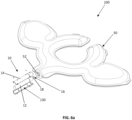
- the drinking bottle 60 is positioned inside the housing cavity 71 of the aerodynamic hump 70. Furthermore the drinking bottle 60 has an arc shape or a curved shape along an arc trajectory. Even more preferably, the shape of the drinking bottle 60 is comparable to the shape of the external surface of the aerodynamic hump 70, which has a curved shape along an arc trajectory.
- the aforementioned shape allows the drinking bottle 60 to occupy at least partially the space inside the housing cavity 71 situated between the inflation device 10 and the external surface of the aerodynamic hump 70.
- the drinking bottle 60 is positioned inside the housing cavity 71 in an intermediate space between the inflation device 10 and the external wall of the aerodynamic hump 70 of the protective garment 1000.
- the support plate 30 may have a receiving cavity 32 through which the drinking bottle 60 may be passed so as to be inserted into (or extracted from) the housing cavity 71.
- Said receiving cavity 32 is located in the vicinity of the inflation device 10, in particular is located alongside it, relative to the longitudinal direction of the inflation device 10.
- the receiving cavity 32 is located on the opposite side to the control unit 42, relative to the inflation device 10.
- the inflation device 10 is located in the centre of the support plate and is situated between the control unit 42 and the receiving cavity 32.
- the drinking bottle 60 is rotated about the inflation device 10 so as to pass between a position outside the housing cavity 71 into a position inside the latter.
- the drinking bottle 60 is rotated about an axis corresponding to the longitudinal axis of the inflation device 10, when the latter is positioned in the coupling portion 31 of the support plate 30.
- the drinking bottle 60 may be easily inserted inside (or removed from) the housing cavity 71 of the aerodynamic hump 70 in order to be emptied or filled, without having to displace or extract the other components present inside the same housing cavity 71.
Landscapes
- Health & Medical Sciences (AREA)
- General Health & Medical Sciences (AREA)
- Physical Education & Sports Medicine (AREA)
- Engineering & Computer Science (AREA)
- Textile Engineering (AREA)
- Professional, Industrial, Or Sporting Protective Garments (AREA)
- Polishing Bodies And Polishing Tools (AREA)
- Electronic Switches (AREA)
Claims (19)
- Schutzkleidung (1000) mit einer sichtbaren Außenfläche und einer Innenfläche (80), die geeignet ist, während des Gebrauchs dem Körper eines Benutzers zugewandt zu sein; wobei die Schutzkleidung (1000) ein aufblasbares Element (50) umfasst, das dazu bestimmt ist, zumindest teilweise einen Bereich des Körpers eines Benutzers zu schützen, und eine Aufblasvorrichtung (10), die konfiguriert ist, um das aufblasbare Element (50) aufzublasen, wobei die Schutzkleidung (1000) ferner einen aerodynamischen Höcker (70) umfasst, der konfiguriert ist, um zumindest teilweise einen Bereich auf dem Rücken eines Benutzers zu schützen, und der einen Aufnahmehohlraum (71) definiert, der der Innenfläche (80) zugewandt und konfiguriert ist, um die Aufblasvorrichtung (10) aufzunehmen, wobei die Aufblasvorrichtung (10) mindestens einen Gasgenerator (12) und einen Behälter (14) zum Aufnehmen des mindestens einen Gasgenerators (12) umfasst, wobei der Behälter (14) und der mindestens eine Gasgenerator (12) eine strukturell unabhängige Anordnung definieren und konfiguriert sind, um in Bezug auf das aufblasbare Element (50) als ein einziger Körper gehandhabt zu werden, und wobei die Aufblasvorrichtung (10) eine Kupplungskomponente (18) umfasst und das aufblasbare Element (50) eine Kupplungsgegenkomponente (52) aufweist, wobei die Kupplungskomponente (18) konfiguriert ist, um auf abnehmbare Weise mit der Kupplungsgegenkomponente (52), die dem aufblasbaren Element (50) zugehörig ist, gekoppelt zu werden, dadurch gekennzeichnet, dass die Kleidung eine Zugangszone (15) umfasst, die konfiguriert ist, um Zugang zu dem Aufnahmehohlraum (71) zu ermöglichen.
- Schutzkleidung (1000) nach dem vorstehenden Anspruch, wobei die Schutzkleidung (1000) ein Futter umfasst und die Zugangszone (15) eine im Futter der Kleidung ausgebildete Öffnung ist.
- Schutzkleidung (1000) nach einem der vorstehenden Ansprüche, wobei der Behälter (14) die Form einer rohrförmigen Schale aufweist, die eine innere Aufnahmekammer (130) zur Aufnahme des Gasgenerators (12) definiert.
- Schutzkleidung (1000) nach dem vorstehenden Anspruch, wobei der Behälter (14) einen Hauptkörper (231) und eine Verschlussabdeckung (232) für den Hauptkörper (231) aufweist, wobei der Hauptkörper (231) die Form einer rohrförmigen Schale aufweist, die eine innere Aufnahmekammer (230) zur Aufnahme des Gasgenerators (12) definiert, und wobei der Hauptkörper (231) ein erstes offenes Ende (221) aufweist, wobei das erste offene Ende (221) die Kupplungskomponente (18) des Gasgenerators (12) aufnimmt.
- Schutzkleidung (1000) nach dem vorstehenden Anspruch, wobei der Hauptkörper (231) und die Verschlussabdeckung (232) einstückig miteinander verbunden sind und nur einmal oder irreversibel voneinander gelöst werden können oder durch kalibrierte Bruchmittel verbunden sind.
- Schutzkleidung (1000) nach einem der vorstehenden Ansprüche, wobei die Kupplungskomponente (18) konfiguriert ist, um mit der dem aufblasbaren Element (50) zugeordneten Kupplungsgegenkomponente (52) in dem aerodynamischen Höcker (70) gekoppelt werden kann.
- Schutzkleidung (1000) nach einem der vorstehenden Ansprüche, wobei die Kupplungsgegenkomponente (52) in dem Aufnahmehohlraum (71) des aerodynamischen Höckers (70) angeordnet ist.
- Schutzkleidung (1000) nach dem vorstehenden Anspruch, wobei ein Abschnitt des aufblasbaren Elements (50), das an der Kupplungsgegenkomponente (52) befestigt ist, in dem Aufnahmehohlraum (71) des aerodynamischen Höckers (70) angeordnet ist.
- Schutzkleidung (1000) nach einem der vorstehenden Ansprüche, wobei die Schutzkleidung (1000) eine Trägerplatte (30) umfasst, die in dem Aufnahmehohlraum (71) des aerodynamischen Höckers (71) angeordnet ist, und wobei die Trägerplatte (30) einen Kupplungsabschnitt (31) umfasst, der für eine Verbindung mit der Aufblasvorrichtung (10) konfiguriert ist.
- Schutzkleidung (1000) nach dem vorstehenden Anspruch, wobei eine Verbindung zwischen dem Kupplungsabschnitt (31) der Trägerplatte (30) und der Aufblasvorrichtung (10) eine mechanische Kupplung ist.
- Schutzkleidung (1000) nach Anspruch 9 oder 10, wobei der Behälter (14) und die Trägerplatte (30) aus starrem Material hergestellt sind.
- Schutzkleidung (1000) nach einem der vorstehenden Ansprüche, umfassend eine Steuereinheit (42), die mit der Aufblasvorrichtung (10) in Wirkverbindung steht, um die Aktivierung des Gasgenerators (12) zu steuern.
- Schutzkleidung (1000) nach dem vorstehenden Anspruch, wobei die Steuereinheit (42) im Inneren des Aufnahmehohlraums (71) des aerodynamischen Höckers (70) angeordnet ist.
- Schutzkleidung (1000) nach dem vorstehenden Anspruch in Kombination mit Anspruch 9, 10 oder 11, wobei die Steuereinheit (42) der Trägerplatte (30) auf einer Seite der Aufblasvorrichtung (10) zugehörig ist.
- Schutzkleidung (1000) nach einem der vorstehenden Ansprüche, wobei der Aufnahmehohlraum (71) des aerodynamischen Höckers ferner einen Behälter für trinkbare Flüssigkeiten (60) aufweist.
- Schutzkleidung (1000) nach dem vorstehenden Anspruch, wobei der Behälter für trinkbare Flüssigkeiten (60) eine Bogenform oder eine gekrümmte Form entlang einer Bogenbahn aufweist und wobei die Aufblasvorrichtung (10) innerhalb einer durch den Behälter für trinkbare Flüssigkeiten (60) gebildeten Aushöhlung positioniert ist.
- Schutzkleidung (1000) nach Anspruch 16 in Kombination mit einem der Ansprüche 9, 10, 11 oder 14, wobei die Trägerplatte (30) einen Durchgangshohlraum (32) umfasst, der konfiguriert ist, um einen Durchgang des Behälters für trinkbare Flüssigkeiten (60) zur Innenseite und zur Außenseite des Aufnahmehohlraums (71) des aerodynamischen Höckers (70) hin zu ermöglichen.
- Schutzkleidung (1000) nach einem der vorstehenden Ansprüche, wobei die Schutzkleidung (1000) eine Motorradkleidung oder ein Motorradanzug ist.
- Schutzkleidung (1000) nach einem der vorstehenden Ansprüche, wobei eine Bedingung für das Entfernen der Aufblasvorrichtung einer Bedingung für den Zugang zum aerodynamischen Höcker von der Innenfläche der Kleidung (1000) aus entspricht.
Applications Claiming Priority (1)
| Application Number | Priority Date | Filing Date | Title |
|---|---|---|---|
| IT102021000012506A IT202100012506A1 (it) | 2021-05-14 | 2021-05-14 | Indumento protettivo |
Publications (3)
| Publication Number | Publication Date |
|---|---|
| EP4088604A1 EP4088604A1 (de) | 2022-11-16 |
| EP4088604B1 true EP4088604B1 (de) | 2024-05-22 |
| EP4088604C0 EP4088604C0 (de) | 2024-05-22 |
Family
ID=77519484
Family Applications (1)
| Application Number | Title | Priority Date | Filing Date |
|---|---|---|---|
| EP22173275.3A Active EP4088604B1 (de) | 2021-05-14 | 2022-05-13 | Schutzkleidung |
Country Status (2)
| Country | Link |
|---|---|
| EP (1) | EP4088604B1 (de) |
| IT (1) | IT202100012506A1 (de) |
Families Citing this family (2)
| Publication number | Priority date | Publication date | Assignee | Title |
|---|---|---|---|---|
| EP4520209A1 (de) | 2023-08-24 | 2025-03-12 | Dainese S.p.A. | Tragbares schutzgerät |
| EP4620338A1 (de) * | 2024-03-20 | 2025-09-24 | Dainese S.p.A. | Gas generator |
Family Cites Families (5)
| Publication number | Priority date | Publication date | Assignee | Title |
|---|---|---|---|---|
| DE19703805C2 (de) * | 1996-02-05 | 2001-05-03 | Werner Herrmann | Sicherheitskleidung für einen Motorradfahrer |
| US6298487B1 (en) * | 2000-09-15 | 2001-10-09 | James W. Mayhew | Survival article of clothing |
| JP4968782B2 (ja) * | 2007-03-30 | 2012-07-04 | 本田技研工業株式会社 | エアバッグジャケット |
| ITTV20120084A1 (it) * | 2012-05-15 | 2013-11-16 | Alpinestars Res Srl | Dispositivo di protezione autonomo ed indossabile e complesso di abbigliamento protettivo |
| IT201900003315A1 (it) * | 2019-03-07 | 2020-09-07 | Sas Access Equip Motos France | Gobba aereodinamica perfezionata per indumento |
-
2021
- 2021-05-14 IT IT102021000012506A patent/IT202100012506A1/it unknown
-
2022
- 2022-05-13 EP EP22173275.3A patent/EP4088604B1/de active Active
Also Published As
| Publication number | Publication date |
|---|---|
| EP4088604C0 (de) | 2024-05-22 |
| EP4088604A1 (de) | 2022-11-16 |
| IT202100012506A1 (it) | 2022-11-14 |
Similar Documents
| Publication | Publication Date | Title |
|---|---|---|
| EP4046514B1 (de) | Aufblasvorrichtung und persönliche schutzvorrichtung einschliesslich der aufblasvorrichtung | |
| EP4088604B1 (de) | Schutzkleidung | |
| CN104411194B (zh) | 安装有可充气的保护器的内衬和保护性服饰组件 | |
| EP2673190B1 (de) | Aufblasbarer schwimmanzug | |
| KR102843907B1 (ko) | 웨어러블 보호 디바이스 | |
| KR101849050B1 (ko) | 에어백 급팽창 장치 및 그것을 갖는 안전 자켓 | |
| WO2002054895A3 (en) | Inflatable safety vest with a cartridge actuation mechanism | |
| JPH02270696A (ja) | スクーバダイビング用浮力調整装置 | |
| CN115835793A (zh) | 可穿戴保护装置 | |
| US20020026142A1 (en) | Feeding apparatus for breathing masks that allows food and drink intake when the mask is in use | |
| EP4144418B1 (de) | Rucksack für sturzsicherung | |
| US9446826B2 (en) | Survival aid, in particular for swimmers and for those taking part in water sports | |
| US7299507B1 (en) | Protective harness for a motorcycle rider | |
| EP4192279A1 (de) | Elektronische zigarettenvorrichtung mit temperaturaktiviertem batterieauslassanschluss | |
| GB2382121A (en) | Poppet valve for safety cushion | |
| EP4434382B1 (de) | Füllvorrichtung | |
| EP3250064B1 (de) | Entfernbares elektronisches system zur aktivierung der auslösung einer aufblasbaren sicherheitsweste | |
| EP4327685B1 (de) | Tragbares schutzgerät | |
| EP2740376B1 (de) | Kleidungsstück, das zur Verbindung mit einer aufblasbaren Schutzeinrichtung ausgelegt ist | |
| CN216363714U (zh) | 煤矿用的安全保护装置 | |
| CN211153910U (zh) | 一种可穿戴式智能型身体保护气囊防护服 | |
| US20260000143A1 (en) | Protection device and protection method | |
| CN119894401A (zh) | 包括可充胀构件的可穿戴保护装置和用于安全地激活所述可穿戴保护装置的可充胀构件的方法 | |
| GB2176578A (en) | Valve protector | |
| CN205757833U (zh) | 汽车钥匙便携包 |
Legal Events
| Date | Code | Title | Description |
|---|---|---|---|
| PUAI | Public reference made under article 153(3) epc to a published international application that has entered the european phase |
Free format text: ORIGINAL CODE: 0009012 |
|
| STAA | Information on the status of an ep patent application or granted ep patent |
Free format text: STATUS: THE APPLICATION HAS BEEN PUBLISHED |
|
| AK | Designated contracting states |
Kind code of ref document: A1 Designated state(s): AL AT BE BG CH CY CZ DE DK EE ES FI FR GB GR HR HU IE IS IT LI LT LU LV MC MK MT NL NO PL PT RO RS SE SI SK SM TR |
|
| STAA | Information on the status of an ep patent application or granted ep patent |
Free format text: STATUS: REQUEST FOR EXAMINATION WAS MADE |
|
| 17P | Request for examination filed |
Effective date: 20230515 |
|
| RBV | Designated contracting states (corrected) |
Designated state(s): AL AT BE BG CH CY CZ DE DK EE ES FI FR GB GR HR HU IE IS IT LI LT LU LV MC MK MT NL NO PL PT RO RS SE SI SK SM TR |
|
| GRAP | Despatch of communication of intention to grant a patent |
Free format text: ORIGINAL CODE: EPIDOSNIGR1 |
|
| STAA | Information on the status of an ep patent application or granted ep patent |
Free format text: STATUS: GRANT OF PATENT IS INTENDED |
|
| INTG | Intention to grant announced |
Effective date: 20231220 |
|
| GRAS | Grant fee paid |
Free format text: ORIGINAL CODE: EPIDOSNIGR3 |
|
| GRAA | (expected) grant |
Free format text: ORIGINAL CODE: 0009210 |
|
| STAA | Information on the status of an ep patent application or granted ep patent |
Free format text: STATUS: THE PATENT HAS BEEN GRANTED |
|
| AK | Designated contracting states |
Kind code of ref document: B1 Designated state(s): AL AT BE BG CH CY CZ DE DK EE ES FI FR GB GR HR HU IE IS IT LI LT LU LV MC MK MT NL NO PL PT RO RS SE SI SK SM TR |
|
| REG | Reference to a national code |
Ref country code: GB Ref legal event code: FG4D |
|
| REG | Reference to a national code |
Ref country code: CH Ref legal event code: EP |
|
| REG | Reference to a national code |
Ref country code: DE Ref legal event code: R096 Ref document number: 602022003546 Country of ref document: DE |
|
| REG | Reference to a national code |
Ref country code: IE Ref legal event code: FG4D |
|
| U01 | Request for unitary effect filed |
Effective date: 20240620 |
|
| U07 | Unitary effect registered |
Designated state(s): AT BE BG DE DK EE FI FR IT LT LU LV MT NL PT SE SI Effective date: 20240628 |
|
| PG25 | Lapsed in a contracting state [announced via postgrant information from national office to epo] |
Ref country code: IS Free format text: LAPSE BECAUSE OF FAILURE TO SUBMIT A TRANSLATION OF THE DESCRIPTION OR TO PAY THE FEE WITHIN THE PRESCRIBED TIME-LIMIT Effective date: 20240922 |
|
| PG25 | Lapsed in a contracting state [announced via postgrant information from national office to epo] |
Ref country code: HR Free format text: LAPSE BECAUSE OF FAILURE TO SUBMIT A TRANSLATION OF THE DESCRIPTION OR TO PAY THE FEE WITHIN THE PRESCRIBED TIME-LIMIT Effective date: 20240522 |
|
| PG25 | Lapsed in a contracting state [announced via postgrant information from national office to epo] |
Ref country code: GR Free format text: LAPSE BECAUSE OF FAILURE TO SUBMIT A TRANSLATION OF THE DESCRIPTION OR TO PAY THE FEE WITHIN THE PRESCRIBED TIME-LIMIT Effective date: 20240823 |
|
| PG25 | Lapsed in a contracting state [announced via postgrant information from national office to epo] |
Ref country code: ES Free format text: LAPSE BECAUSE OF FAILURE TO SUBMIT A TRANSLATION OF THE DESCRIPTION OR TO PAY THE FEE WITHIN THE PRESCRIBED TIME-LIMIT Effective date: 20240522 |
|
| PG25 | Lapsed in a contracting state [announced via postgrant information from national office to epo] |
Ref country code: PL Free format text: LAPSE BECAUSE OF FAILURE TO SUBMIT A TRANSLATION OF THE DESCRIPTION OR TO PAY THE FEE WITHIN THE PRESCRIBED TIME-LIMIT Effective date: 20240522 |
|
| PG25 | Lapsed in a contracting state [announced via postgrant information from national office to epo] |
Ref country code: PL Free format text: LAPSE BECAUSE OF FAILURE TO SUBMIT A TRANSLATION OF THE DESCRIPTION OR TO PAY THE FEE WITHIN THE PRESCRIBED TIME-LIMIT Effective date: 20240522 Ref country code: NO Free format text: LAPSE BECAUSE OF FAILURE TO SUBMIT A TRANSLATION OF THE DESCRIPTION OR TO PAY THE FEE WITHIN THE PRESCRIBED TIME-LIMIT Effective date: 20240822 Ref country code: IS Free format text: LAPSE BECAUSE OF FAILURE TO SUBMIT A TRANSLATION OF THE DESCRIPTION OR TO PAY THE FEE WITHIN THE PRESCRIBED TIME-LIMIT Effective date: 20240922 Ref country code: HR Free format text: LAPSE BECAUSE OF FAILURE TO SUBMIT A TRANSLATION OF THE DESCRIPTION OR TO PAY THE FEE WITHIN THE PRESCRIBED TIME-LIMIT Effective date: 20240522 Ref country code: GR Free format text: LAPSE BECAUSE OF FAILURE TO SUBMIT A TRANSLATION OF THE DESCRIPTION OR TO PAY THE FEE WITHIN THE PRESCRIBED TIME-LIMIT Effective date: 20240823 Ref country code: ES Free format text: LAPSE BECAUSE OF FAILURE TO SUBMIT A TRANSLATION OF THE DESCRIPTION OR TO PAY THE FEE WITHIN THE PRESCRIBED TIME-LIMIT Effective date: 20240522 Ref country code: RS Free format text: LAPSE BECAUSE OF FAILURE TO SUBMIT A TRANSLATION OF THE DESCRIPTION OR TO PAY THE FEE WITHIN THE PRESCRIBED TIME-LIMIT Effective date: 20240822 |
|
| PG25 | Lapsed in a contracting state [announced via postgrant information from national office to epo] |
Ref country code: CZ Free format text: LAPSE BECAUSE OF FAILURE TO SUBMIT A TRANSLATION OF THE DESCRIPTION OR TO PAY THE FEE WITHIN THE PRESCRIBED TIME-LIMIT Effective date: 20240522 |
|
| PG25 | Lapsed in a contracting state [announced via postgrant information from national office to epo] |
Ref country code: RO Free format text: LAPSE BECAUSE OF FAILURE TO SUBMIT A TRANSLATION OF THE DESCRIPTION OR TO PAY THE FEE WITHIN THE PRESCRIBED TIME-LIMIT Effective date: 20240522 Ref country code: SK Free format text: LAPSE BECAUSE OF FAILURE TO SUBMIT A TRANSLATION OF THE DESCRIPTION OR TO PAY THE FEE WITHIN THE PRESCRIBED TIME-LIMIT Effective date: 20240522 |
|
| PG25 | Lapsed in a contracting state [announced via postgrant information from national office to epo] |
Ref country code: SK Free format text: LAPSE BECAUSE OF FAILURE TO SUBMIT A TRANSLATION OF THE DESCRIPTION OR TO PAY THE FEE WITHIN THE PRESCRIBED TIME-LIMIT Effective date: 20240522 Ref country code: RO Free format text: LAPSE BECAUSE OF FAILURE TO SUBMIT A TRANSLATION OF THE DESCRIPTION OR TO PAY THE FEE WITHIN THE PRESCRIBED TIME-LIMIT Effective date: 20240522 Ref country code: CZ Free format text: LAPSE BECAUSE OF FAILURE TO SUBMIT A TRANSLATION OF THE DESCRIPTION OR TO PAY THE FEE WITHIN THE PRESCRIBED TIME-LIMIT Effective date: 20240522 |
|
| REG | Reference to a national code |
Ref country code: DE Ref legal event code: R097 Ref document number: 602022003546 Country of ref document: DE |
|
| PLBE | No opposition filed within time limit |
Free format text: ORIGINAL CODE: 0009261 |
|
| STAA | Information on the status of an ep patent application or granted ep patent |
Free format text: STATUS: NO OPPOSITION FILED WITHIN TIME LIMIT |
|
| 26N | No opposition filed |
Effective date: 20250225 |
|
| U20 | Renewal fee for the european patent with unitary effect paid |
Year of fee payment: 4 Effective date: 20250522 |
|
| REG | Reference to a national code |
Ref country code: CH Ref legal event code: H13 Free format text: ST27 STATUS EVENT CODE: U-0-0-H10-H13 (AS PROVIDED BY THE NATIONAL OFFICE) Effective date: 20251223 |
|
| PG25 | Lapsed in a contracting state [announced via postgrant information from national office to epo] |
Ref country code: CH Free format text: LAPSE BECAUSE OF NON-PAYMENT OF DUE FEES Effective date: 20250531 |
|
| PG25 | Lapsed in a contracting state [announced via postgrant information from national office to epo] |
Ref country code: MC Free format text: LAPSE BECAUSE OF FAILURE TO SUBMIT A TRANSLATION OF THE DESCRIPTION OR TO PAY THE FEE WITHIN THE PRESCRIBED TIME-LIMIT Effective date: 20240522 |