EP4046514B1 - Aufblasvorrichtung und persönliche schutzvorrichtung einschliesslich der aufblasvorrichtung - Google Patents
Aufblasvorrichtung und persönliche schutzvorrichtung einschliesslich der aufblasvorrichtung Download PDFInfo
- Publication number
- EP4046514B1 EP4046514B1 EP22157262.1A EP22157262A EP4046514B1 EP 4046514 B1 EP4046514 B1 EP 4046514B1 EP 22157262 A EP22157262 A EP 22157262A EP 4046514 B1 EP4046514 B1 EP 4046514B1
- Authority
- EP
- European Patent Office
- Prior art keywords
- gas generator
- inflatable element
- component
- coupling
- inflation device
- Prior art date
- Legal status (The legal status is an assumption and is not a legal conclusion. Google has not performed a legal analysis and makes no representation as to the accuracy of the status listed.)
- Active
Links
Images


Classifications
-
- A—HUMAN NECESSITIES
- A41—WEARING APPAREL
- A41D—OUTERWEAR; PROTECTIVE GARMENTS; ACCESSORIES
- A41D13/00—Professional, industrial or sporting protective garments, e.g. surgeons' gowns or garments protecting against blows or punches
- A41D13/015—Professional, industrial or sporting protective garments, e.g. surgeons' gowns or garments protecting against blows or punches with shock-absorbing means
- A41D13/018—Professional, industrial or sporting protective garments, e.g. surgeons' gowns or garments protecting against blows or punches with shock-absorbing means inflatable automatically
-
- A—HUMAN NECESSITIES
- A41—WEARING APPAREL
- A41D—OUTERWEAR; PROTECTIVE GARMENTS; ACCESSORIES
- A41D2600/00—Uses of garments specially adapted for specific purposes
- A41D2600/10—Uses of garments specially adapted for specific purposes for sport activities
- A41D2600/102—Motorcycling
Definitions
- the present invention relates generally to the sector of providing protection by means of an inflatable element, so as to protect a user from impacts, following falling or sliding, for example when performing any activity or when travelling on a means of transport, such as a vehicle, preferably a two-wheeled vehicle, or any other means of transport, such as a horse or other animal, sports equipment, such as a pair of skis or a bobsleigh, or similar means of transport.
- a means of transport such as a vehicle, preferably a two-wheeled vehicle, or any other means of transport, such as a horse or other animal, sports equipment, such as a pair of skis or a bobsleigh, or similar means of transport.
- the present disclosure relates to an inflation device for inflating an inflatable element for protecting a user in the event of falls and/or impacts of various types.
- protection devices including inflatable elements, which are inflated in the event of an impact by an inflation device which is in fluid communication with the said inflatable element.
- an inflation device is formed by a fluid source, such as a canister which contains compressed gas and which is opened by means of a punch, or a small explosion, or a pyrotechnic gas canister which expands, also following a small explosion, which is managed by means of an electric activation signal.
- gas generator Any form of fluid source intended to determine the outflow of pressurised gas into an inflatable element is referred to in the continuation of the present disclosure by the term "gas generator".
- Protection devices are normally formed by an inflatable element, the aforementioned gas generator, sensors for detecting the fall or the impact and at least one control unit for managing the activation of the gas generator in order to inflate the inflatable element.
- the entire protection device is then associated with a garment, for example inside a pocket, or joined to it by means of a connection system of the known type.
- the gas generator is arranged inside the inflatable element, for reasons of convenience, so as to facilitate the fluid connection with the inflatable element.
- An inflation device according to the preamble of claim 1 is known for example from US 6,158,380 .
- One problem forming the basis of the present disclosure is that of providing an inflation device which allows a user to replace a gas generator without necessarily removing the inflatable element and which may also have other advantages and also providing a protection device which includes said inflation device.
- the present disclosure is based on the recognition by the inventor of the present disclosure that it is possible to incorporate the gas generator in a container and form a single body therewith.
- the container acts as a handle or gripping body for the gas generator.
- the container consists of a closed container which may be opened in an irreversible manner at the time of use of the gas generator, so as to open a gas outlet zone and allow the gas generator to be placed in fluid communication with the inflatable element.
- the container may be formed by two shells which are joined together by calibrated breakage means which are broken at the time of use. These calibrated breakage means are, for example, breakable bridge-pieces between the two shells.
- the container is therefore able to prevent direct contact between an end user and the gas generator.
- the assembly formed by the container and the gas generator may then be coupled to an inflatable element by means of a detachable coupling device. In this way, a user may change only the gas generator without having to remove the inflatable element.
- the inflatable element may be configured to allow several inflation operations and ensure the same protection performance after a number of inflation operations.
- the main advantage therefore consists in the fact that it allows direct contact with the gas generator to be avoided since the user may handle the container or only one of the two shells if the other one is removed following breakage.
- the gas generator container therefore acts as grip for the gas generator.
- a user may handle the gas generator by means of the container and connect by means of coupling the inflation device to the inflatable element in a quick and safe manner.
- the inflation device may advantageously be arranged in a garment so as to be easily reached by a user.
- a user may avoid coming into direct contact with the gas generator and avoid the risks associated with direct handling thereof.
- each embodiment may have one or more of the advantages listed above; in any case it is nevertheless not necessary that each embodiment should have simultaneously all the advantages listed.
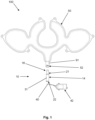
- the reference number 10 indicates a personal inflation device according to an embodiment of the present disclosure.
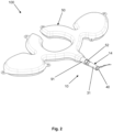
- the inflation device 10 is able to inflate an inflatable element 50.
- the inflatable element 50 is intended to protect at least partially an area of a user's body.
- the inflation device 10 forms part of a personal protection device 100 which includes the aforementioned inflatable element 50.
- the inflatable element 50 may be a single bag.
- the inflatable element 50 may be made using the technology described in patent application PCT/IB2009/055512 and in patent application PCT/IT2009/000547 , or more preferably using the technology described in patent application WO2016178143A1 , or even more preferably in patent application WO2017163196A1 .
- This inflatable element 50 is intended to protect at least partially a body area of the user, for example a top area of a user's torso.
- said inflatable element 50 may be connected to the inflation device 10 in an area of the spinal column.
- the connection area is however not an essential characteristic of the present disclosure.
- the connection is advantageously provided where said connection may be easily accessed by a user.
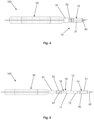
- the inflation device 10 includes at least one gas generator 12 and a container 14 for containing said at least one gas generator 12.
- the gas generator 12 is provided with a region 16 intended for the passage of gas, namely a region which, when the gas generator 12 is activated, allows gas to pass towards the inflatable element 50.
- the gas generator 12 may be provided, as is known, with a shut-off valve, not visible in the drawings.
- the gas generator 12 may be a canister containing compressed cold gas, such as helium.
- the gas generator 12 may be a gas generator of the pyrotechnic or hybrid type or of other types known in the state of the art.
- the container 14 and the at least one gas generator 12 form a structurally independent assembly, configured to be handled as a single body, with respect to said inflatable element 50.
- the inflation device 10 comprises a coupling component 18 configured to be coupled in a detachable manner with a coupling counter-component 52 associated with said inflatable element 50.
- the container 14 has the form of a tubular shell defining an internal housing chamber 30 for housing the gas generator 12.
- the container 14 consists of a body which may be easily gripped by a user.
- the container 14 includes a substantially closed single-piece body formed by two shells which can be separated from each other in an irreversible manner, for example by breakage of calibrated breakage means.
- the container 14 comprises a main body 31, having a tubular shape, and a shell in the form of a closing cover 32, configured to close off the main body in the manner of a hood. It therefore consists of an end shell for closing off the main body 31 of the container 14.
- the container 14 may in turn comprise an end cover which closes off an end zone of the main body 31.
- the end cover may be a slider body configured so as to be able to slide inside at least one insertion guide positioned in the proximity of the end zone of the main body 31.
- the main body 31 defines preferably a first open end 21, which may receive the coupling component 18 of the gas generator 12, and an opening in the vicinity of the end region, namely a second open end 22.
- the main body 31 and the closing cover 32 are made of rigid material.
- the rigid material facilitates the management of the components as indicated hereinbelow.
- the main body 31 and the closing cover 32 are, as mentioned, initially connected to form a single piece.
- the container 14 is a closed single-piece body and connection means may be provided between the main body 31 and the closing cover 32.
- the connection means may be calibrated breakage bridge-pieces, also called breakable bridge-pieces. These calibrated breakage bridge-pieces may be broken by a user by means of relative rotation of the main body 31 and the closing cover 32 in opposite directions.
- a user who is holding the container 14 may rotate at least either the main body 31 or the closing cover 32 in order to break the calibrated bridge-pieces so as to be able to separate the main body 31 and the closing cover 32.
- the coupling which is formed between the inflation device 10 and the inflatable element 50 is a mechanical coupling, for example a so-called quick-release coupling, quick-fit coupling, screw connection or a similar mechanical coupling which is known to the person skilled in the art. More preferably, it consists of a mechanical coupling of the male/female type.
- the inflation device therefore comprises one between a male coupling component and a female coupling counter-component.
- the coupling component 18 is placed in the region 16 of the gas generator 12 intended for the outflow of the inflation gas.
- the coupling component 18, for example the aforementioned male or female component, may be located in the vicinity of the region 16 intended for the gas outflow and be coupled with the other coupling component 52 which in turn may be located on the vicinity of a gas intake opening of the inflatable element. In this way, as soon as the inflation device 10 is coupled to the inflatable element 50, it is possible to establish fluid communication between the gas generator 12 and the inflatable element 50 when the gas generator is activated 12.
- the gas generator 12 comprises said coupling component 18.
- the gas generator 12 is suitably modified to allow coupling. This solution ensures a greater pressure tightness, considering the fact that the pressure comes from the gas generator.
- the gas generator 12 is shaped to comprise said coupling component as one piece or integrally.
- the coupling component 18 and the gas generator 12 form a single piece, namely they are components which are integrally made as a single body.
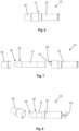
- the coupling component 18 comprises a first plug-in component 71 connected to the gas generator 12, and the coupling counter-component comprises a first guide seat 81.
- the first guide seat is preferably configured to allow sliding of the first plug-in component 71 in such a way as to couple in a detachable manner the gas generator 12 to the inflatable element 50.
- the first plug-in component 71 may slide along the first guide seat 81 so as to couple in a detachable manner together the coupling component 18 and the coupling counter-component 52.
- the first guide seat 81 has an L-shaped form or a right-angled form.
- the L-shaped or right-angled form allows the first plug-in component 71 to slide along the first guide seat 81 and, once the angle of the L-shaped or right-angled form is reached, by means of relative rotation of the coupling component 18 and the coupling counter-component 52 it is possible to prevent a further sliding action of the first plug-in component 71. In this way uncoupling of the coupling component 18 and the coupling counter-component 52, and therefore of the gas generator 12 and the inflatable element 50, may be prevented.
- the inflation device 10 further comprises a ring nut body associated with the coupling counter-component 52 and configured to prevent the first plug-in component 71 from coming out of the first guide seat 81.
- the ring nut body may prevent sliding in the opposite direction of the first plug-in component 71, for example by means of rotation of the ring-nut body about the coupling counter-component 52.
- the container 14 has in the end region the aforementioned second open end 22 which may receive an electrical connection component 40 configured so that it may be connected to a control unit 42 in order to control activation of the gas generator 12.
- the inflation device 10 comprises a second plug-in component 72 connected to said gas generator 12, and the main body 31 of the container 14 comprises a second guide seat 82.
- the second guide seat 82 may be configured to allow sliding of the second plug-in component 72 in such a way as to guide insertion of the gas generator 12 inside the internal housing chamber 30 of the main body 31.
- the inflation device 10 comprises an annular body 91 configured to surround the coupling counter-component 52 in such a way as to support a connection between the coupling counter-component 52 and the inflatable element 50, for example exerting a given pressure.
- the gas generator 12 is shaped like a canister and, as mentioned above, the container 14 has a tubular form for receiving the gas generator 12, and even more preferably the gas generator 12 is modified to include the coupling component 18 which, in the embodiment, is a male engaging component.
- the main body 31 of the container 14 has a first open end 21, said first open end 21 receiving the coupling component 18 of the gas generator 12.
- the gas generator 12 after being inserted inside the container 14, together with the latter, may be handled as a single body by the user.
- the gas generator 12 may be coupled to the coupling counter-component 52 of the inflatable element 50 by means of direct gripping of the container 14.
- the main body 31 of the container 14 therefore acts as a handle or gripping body for the gas generator 12, for example during coupling together of the gas generator 12 and the inflatable element 50.
- the main body 31 of the container 14 may be advantageously configured to include the aforementioned second open end 22.
- the second open end may be closed by the aforementioned end cover, which may be said slider body or a slidable body configured so that it can slide inside the at least one insertion guide positioned close to the end zone of the main body 31.
- the end body may be uncoupled from the main body 31, for example by means of sliding, so as to define the second open end 22, which may receive the electrical connection component 40.
- the container 14 may therefore be designed so as not to prevent, on the one hand, coupling with the inflatable element 50 and, on the other hand, connection with the control unit 42.
- control unit 42 it is pointed out that, in a known manner, it may be configured for the opening of the aforementioned shut-off valve of the gas generator 12 depending on the detection of the state of the user; for example, said control unit 42 may implement a fall prediction system which allows early identification of the fall event and a reliable prediction thereof by means of accelerometric sensors and a unit for processing the signals produced by the said sensors.
- the device according to the present disclosure may also be applied using an activation cable connected to a vehicle ridden/driven by a user, which cable activates inflation of the inflatable element following the movement of the user away from the vehicle, for example following a fall or a sudden impact. Use of a cable is employed in particular in the horse-riding sector.
- the activation modes although being an aspect of particular importance for effective operation of the device, will not be further described in greater detail since they are methods which are essentially already known to a person skilled in the art of protection of an individual from sudden impacts.
- the inflation device forms part of a personal protection device 100 comprising the inflatable element 50 and the inflation device 10 according to one or more of the characteristics described above.
- the inflatable element 50 comprises said coupling counter-component 52.
- the gas generator 14 is a body which has a region 16 intended for a gas outflow and said coupling component 18 is configured to connect said gas outflow region 16 to the inflatable element 50.
- a coupled condition of the inflation device 10 and the inflatable element 50 corresponds to a condition of possible fluid communication between the gas generator 12 and the inflatable element 50.
- the protection device 100 may include in a known manner the control unit 42 and sensor means (not shown) designed to detect the fall or an impact for a user.
- the personal protection device 100 may be worn on its own as a separate garment, optionally lined with a fabric aesthetically attractive for a user, or a comfortable and practical fabric, or may be incorporated in suitable pockets inside a garment, such as a motorcyclist's suit or jacket.
- the personal protection device 100 may be associated with a wearable article 1000, such as a garment, or a motorcyclist's suit such as that shown in Figure 9 .
- the garment therefore comprises the personal protection device 100 and the inflation device 10.
- Figure 9 shows only a rear part of the personal protection device 100, transparent with respect to the garment.
- the present disclosure also relates to a method for assembling a personal protection device. According to the method, before associating the gas generator 12 with the inflatable element 50, the gas generator 12 is arranged inside a container 14 so as to define a structurally independent assembly, configured to be handled as a single body, with respect to said inflatable element 50.
- the container 14 therefore acts as a gripping body for the gas generator 12.
- the structurally independent assembly thus obtained is then coupled in a detachable manner to the inflatable element 50 by means of a detachable coupling device.
- the detachable coupling device includes preferably the coupling component 18 and the coupling counter-component 52.
- the gas generator 12 is arranged inside the container 14 formed by the main body 31 and the closing cover 32 which covers at least partially a gas outflow region 16 of the gas generator 12.
- the closing cover 32 is removed from the main body 31 so as to allow fluid communication between the gas outflow region 16 and the inflatable element 50 following coupling together.
- the closing cover 32 is joined together initially as one piece to the main body and is broken in an irreversible manner.
- the device consists of a mechanical coupling device. Therefore, the structurally independent assembly is coupled to the inflatable element 50 by means of a mechanical coupling and one coupling component is one between a coupling component and a coupling counter-component associated with the gas generator 12 and one component is the other between a coupling component and a coupling counter-component associated with the inflatable element 50.
- the gas generator 14 is a body shaped like a canister having said region 16 intended for a gas outflow. In this way, when the gas generator is coupled to the inflatable element in said region 16, simultaneously the gas generator is coupled to the inflatable element 50. By so doing, the gas generator 12 may be placed in fluid communication with the inflatable element 50.
- the gas generator is then connected to the control unit 42 in order to control activation of the gas generator 12.
- the coupling counter-component 52 comprises a first guide seat 81, which is for example shaped as an L or a right angle. Even more preferably, the first guide seat 81 is configured to allow sliding of a first plug-in component 71 of the coupling component 18 in such a way as to couple in a detachable manner the coupling component 18 and the coupling counter-component 52.
- the first plug-in component 71 may be connected to the gas generator 12.
- the first plug-in component 71 is slid along the first guide seat 81, which is preferably L-shaped.
- the device 10 comprises a ring nut body associated with the coupling counter-component 52 and configured to prevent the first plug-in component 71 from coming out of the first guide seat 81.
- the ring nut body may be rotated so as to prevent the first plug-in component 71 from sliding out from the first guide seat 81.
- an annular body 91 of the device 10 may surround the coupling counter-component 52 so as to support a connection between the coupling counter-component 52 and the inflatable element 50.
- the coupling together of the gas generator 12 and the container 14 may be assisted by a second plug-in component 72 which is connected to the gas generator 12 and configured to allow sliding along a second guide seat 82 of the container 14.
- the second guide seat 82 may be formed along the main body 31 of the container 14 in such a way as to assist "controlled" insertion of the gas generator inside an internal housing chamber 30 of the main body 31 by means of guided sliding of the second plug-in component 72 along the second guide seat 82.
- the container 14 comprises, even more preferably along the main body 31, a third opening configured to allow viewing of at least one portion of the gas generator 12 contained inside it, for example in order to view an alphanumeric code or a bar code of the gas generator 12.
- the container 14 may be made at least partially of transparent material.
- the second plug-in component 72 is preferably a body separate from the first plug-in component 71. Moreover, the second plug-in component 72 may be replaced by one or more similar elements associated with the gas generator 12 and having the same function described above. For example, the second guide seat 82 may be associated with the gas generator 12 and the second plug-in component 72 may be associated with the container 14, while maintaining a similar method of use.
- the present disclosure also relates to use of a coupling device for coupling an inflatable element of a personal protection device to a gas generator for inflating the inflatable element.
- the gas generator is housed inside a container so as to define a structurally independent assembly, configured to be handled as a single body, with respect to said inflatable element.
- the detachable coupling device is used to allow, when the gas generator is activated, stable fluid communication between the gas generator and the inflatable element.
- the personal protection device may be the personal protection device 100 in accordance with one or more of the characteristics described above.
- the personal protection device is that used in the wearable article 100 or is used to carry out a method described above.
Landscapes
- Health & Medical Sciences (AREA)
- General Health & Medical Sciences (AREA)
- Physical Education & Sports Medicine (AREA)
- Engineering & Computer Science (AREA)
- Textile Engineering (AREA)
- Professional, Industrial, Or Sporting Protective Garments (AREA)
- Shaping By String And By Release Of Stress In Plastics And The Like (AREA)
- Yarns And Mechanical Finishing Of Yarns Or Ropes (AREA)
- Gloves (AREA)
Claims (19)
- Aufblasvorrichtung (10) zum Aufblasen eines aufblasbaren Elements (50), wobei das aufblasbare Element (50) dazu bestimmt ist, eine Region eines Körpers eines Benutzers mindestens teilweise zu schützen, und wobei die Aufblasvorrichtung (10) mindestens einen Gasgenerator (12) und einen Behälter (14) zum Enthalten des mindestens einen Gasgenerators (12) einschließt, und wobei der Behälter (14) und der mindestens eine Gasgenerator (12) eine strukturell unabhängige Anordnung definieren, die konfiguriert ist, um in Bezug auf das aufblasbare Element (50) als ein einziger Körper gehandhabt zu werden, und wobei die Aufblasvorrichtung (10) eine Kopplungskomponente (18) umfasst, die konfiguriert ist, um auf eine lösbare Weise mit einer Kopplungsgegenkomponente (52) gekoppelt zu werden, die mit dem aufblasbaren Element (50) verknüpft ist, dadurch gekennzeichnet, dass der Behälter (14) ein geschlossener Körper ist, umfassend mindestens zwei Schalen, die als ein Stück zusammengefügt sind und nur einmal oder auf eine irreversible Weise voneinander lösbar sind oder durch kalibrierte Bruchmittel verbunden sind.
- Aufblasvorrichtung (10) nach Anspruch 1, wobei die zwei Schalen jeweils einen Hauptkörper (31) und eine Abdeckung (32) zum Schließen des Hauptkörpers (31) einschließen, wobei der Hauptkörper die Form einer rohrförmigen Schale aufweist, die eine innere Aufnahmekammer (30) zum Aufnehmen des Gasgenerators (12) definiert, und wobei der Hauptkörper (31) ein erstes offenes Ende (21) aufweist, wobei das erste offene Ende (21) die Kopplungskomponente (18) des Gasgenerators (12) empfängt.
- Aufblasvorrichtung (10) nach einem der vorstehenden Ansprüche, wobei die zwei Schalen mittels zerbrechlicher Brückenstücke verbunden sind.
- Aufblasvorrichtung (10) nach einem der vorstehenden Ansprüche, wobei die Kopplung eine mechanische Kopplung, vorzugsweise von der Art männlichweiblich, ist und wobei die Kopplungskomponente entweder eine männliche Kopplungskomponente oder eine weibliche Kopplungsgegenkomponente ist.
- Aufblasvorrichtung (10) nach einem der vorstehenden Ansprüche, wobei der Gasgenerator (12) die Kopplungskomponente (18) umfasst oder wobei der Gasgenerator (12) geformt ist, um die Kopplungskomponente (18) als ein Stück oder integral zu umfassen.
- Aufblasvorrichtung (10) nach einem der vorstehenden Ansprüche, wobei die Kopplungskomponente (18) eine erste Einsteckkomponente (71) umfasst, die mit dem Gasgenerator (12) verbunden ist, und wobei die Kopplungsgegenkomponente (52) einen ersten Führungssitz (81) umfasst, der konfiguriert ist, um ein Gleiten der ersten Einsteckkomponente (71) so zu ermöglichen, um den Gasgenerator (12) auf eine lösbare Weise mit dem aufblasbaren Element (50) zu koppeln.
- Aufblasvorrichtung (10) nach dem vorstehenden Anspruch, wobei der erste Führungssitz (81) eine L-förmige Gestalt aufweist.
- Aufblasvorrichtung (10) nach Anspruch 7, umfassend einen Ringmutterkörper, der mit der Kopplungsgegenkomponente (52) verknüpft ist und konfiguriert ist, um ein Herauskommen der ersten Einsteckkomponente (71) aus dem ersten Führungssitz (81) zu verhindern.
- Aufblasvorrichtung (10) nach Anspruch 7 oder 8, wobei der Behälter (14) ein zweites offenes Ende (22) aufweist, wobei das zweite offene Ende (22) eine elektrische Verbindungskomponente (40) mit einer Steuereinheit (42) zum Steuern einer Aktivierung des Gasgenerators (12) empfängt.
- Aufblasvorrichtung (10) nach dem vorstehenden Anspruch, umfassend eine Endabdeckung zum vorübergehenden Abdecken des zweiten offenen Endes (22).
- Aufblasvorrichtung (10) nach einem der vorstehenden Ansprüche in Kombination mit Anspruch 2, umfassend eine zweite Einsteckkomponente (72), die mit dem Gasgenerator (12) verbunden ist, und wobei der Hauptkörper (31) des Behälters (14) einen zweiten Führungssitz (82) umfasst, der konfiguriert ist, um das Gleiten der zweiten Einsteckkomponente (72) so zu ermöglichen, um ein Einsetzen des Gasgenerators (12) in die innere Aufnahmekammer (30) des Hauptkörpers (31) zu führen.
- Persönliche Schutzvorrichtung (100), umfassend ein aufblasbares Element (50) und eine Aufblasvorrichtung (10) nach einem der Ansprüche 1 bis 11.
- Persönliche Schutzvorrichtung (100) nach dem vorstehenden Anspruch, wobei das aufblasbare Element (50) die Kopplungsgegenkomponente (52) umfasst, und wobei der Gasgenerator (12) ein Körper ist, der einen Bereich (16) aufweist, der für den Gasausfluss bestimmt ist, und wobei die Kopplungskomponente (18) konfiguriert ist, um den Gasausflussbereich (16) mit dem aufblasbaren Element (50) zu verbinden, und wobei ein gekoppelter Zustand zwischen der Aufblasvorrichtung (10) und dem aufblasbaren Element (50) einem Zustand zum Ermöglichen einer Fluidkommunikation zwischen dem Gasgenerator (12) und dem aufblasbaren Element (50) entspricht.
- Tragbarer Artikel (1000), wie ein Kleidungsstück, umfassend eine persönliche Schutzvorrichtung (100) nach einem der Ansprüche 12 oder 13.
- Verfahren zum Anordnen einer persönlichen Schutzvorrichtung (100), wobei die persönliche Schutzvorrichtung (100) mindestens ein aufblasbares Element (50) und einen Gasgenerator (12) zum Aufblasen eines aufblasbaren Elements (50) umfasst, und wobei vor dem Verknüpfen des Gasgenerators (12) mit dem aufblasbaren Element (50) der Gasgenerator (12) in einem Behälter (14) eingerichtet wird, um eine strukturell unabhängige Anordnung zu definieren, die konfiguriert ist, um in Bezug auf das aufblasbare Element (50) als ein einziger Körper gehandhabt zu werden, und wobei die strukturell unabhängige Anordnung dann mittels einer Kopplungsvorrichtung auf eine lösbare Weise mit dem aufblasbaren Element (50) gekoppelt wird, dadurch gekennzeichnet, dass der Behälter (14) ein geschlossener Körper ist, umfassend mindestens zwei Schalen, die als ein Stück zusammengefügt sind, und wobei, um den Gasgenerators zu verwenden, eine Schale von der anderen Schale irreversibel oder durch kalibrierte Bruchmittel oder nur einmal gelöst wird.
- Verfahren nach Anspruch 15, wobei die zwei Schalen jeweils einen Hauptkörper (31), der die Form einer röhrenförmigen Schale aufweist, die eine innere Aufnahmekammer (30) zum Aufnehmen des Gasgenerators (12) definiert, und eine Abdeckung (32) zum Schließen des Hauptkörpers (31) umfassen, wobei die Abdeckung (32) auf eine lösbare Weise mit dem Hauptkörper (31) verknüpft ist und wobei die Abdeckung (32) von dem Hauptkörper (31) entkoppelt wird, bevor die strukturell unabhängige Anordnung auf eine lösbare Weise mit dem aufblasbaren Element (50) gekoppelt wird.
- Verfahren nach einem der vorstehenden Ansprüche 15 oder 16, wobei die Schalen durch Brechen von zerbrechlichen Brückenstücken voneinander gelöst werden.
- Verfahren nach einem der Ansprüche 15 bis 17, wobei die strukturell unabhängige Anordnung mittels einer mechanischen Kopplung mit dem aufblasbaren Element (50) gekoppelt wird, und wobei eine Kopplungskomponente eine zwischen einer Kopplungskomponente (18) und einer Kopplungsgegenkomponente ist, die mit dem Gasgenerator (12) verknüpft ist, und eine Komponente die andere zwischen einer Kopplungskomponente und einer Kopplungsgegenkomponente (52) ist, die mit dem aufblasbaren Element (50) verknüpft ist, und wobei der Gasgenerator (14) ein Körper ist, der wie ein Kanister geformt ist, der einen Bereich (16) aufweist, der für den Ausfluss des Gases bestimmt ist, und wobei der Gasgenerator (12) in diesem Bereich (16) mit dem aufblasbaren Element (50) gekoppelt ist, und wobei, wenn der Gasgenerator (12) mit dem aufblasbaren Element (50) gekoppelt ist, der Gasgenerator (12) in einen Zustand der Fluidkommunikation mit dem aufblasbaren Element (50) gebracht werden kann, und wobei der Gasgenerator mit einer Steuereinheit (42) zum Steuern einer Aktivierung des Gasgenerators (12) verbunden ist.
- Verwendung einer lösbaren Kopplungsvorrichtung zum Koppeln auf eine lösbare Weise eines aufblasbaren Elements (50) einer persönlichen Schutzvorrichtung (100) mit einem Gasgenerator zum Aufblasen des aufblasbaren Elements (50), und wobei der Gasgenerator (12) in einem Behälter (14) aufgenommen ist, um eine strukturell unabhängige Anordnung auszubilden, die konfiguriert ist, um in Bezug auf das aufblasbare Element (50) als ein einziger Körper gehandhabt zu werden, und wobei die lösbare Kopplungsvorrichtung verwendet wird, um eine stabile Flüssigkeitskommunikation zwischen dem Gasgenerator (12) und dem aufblasbaren Element zu ermöglichen,
wobei die persönliche Schutzvorrichtung diese nach einem der Ansprüche 12 oder 13 ist, oder wobei die persönliche Schutzvorrichtung in dem tragbaren Artikel (1000) nach Anspruch 14 angewendet wird, oder um ein Verfahren nach einem der Ansprüche 15 bis 18 durchzuführen.
Applications Claiming Priority (1)
| Application Number | Priority Date | Filing Date | Title |
|---|---|---|---|
| IT102021000003803A IT202100003803A1 (it) | 2021-02-18 | 2021-02-18 | Dispositivo di gonfiaggio e dispositivo di protezione personale includente detto dispositivo di gonfiaggio |
Publications (3)
| Publication Number | Publication Date |
|---|---|
| EP4046514A1 EP4046514A1 (de) | 2022-08-24 |
| EP4046514B1 true EP4046514B1 (de) | 2024-07-24 |
| EP4046514C0 EP4046514C0 (de) | 2024-07-24 |
Family
ID=75850481
Family Applications (1)
| Application Number | Title | Priority Date | Filing Date |
|---|---|---|---|
| EP22157262.1A Active EP4046514B1 (de) | 2021-02-18 | 2022-02-17 | Aufblasvorrichtung und persönliche schutzvorrichtung einschliesslich der aufblasvorrichtung |
Country Status (2)
| Country | Link |
|---|---|
| EP (1) | EP4046514B1 (de) |
| IT (1) | IT202100003803A1 (de) |
Families Citing this family (4)
| Publication number | Priority date | Publication date | Assignee | Title |
|---|---|---|---|---|
| IT202200017448A1 (it) | 2022-08-22 | 2024-02-22 | Dainese Spa | Dispositivo di protezione indossabile |
| IT202200021045A1 (it) * | 2022-10-12 | 2024-04-12 | Dainese Spa | Dispositivo di collegamento a boccola e dispositivo di protezione personale includente detto dispositivo di collegamento a boccola |
| IT202200022623A1 (it) * | 2022-11-04 | 2024-05-04 | Alpinestars Res Spa | Dispositivo di protezione gonfiabile per un dispositivo di protezione indossabile, dispositivo di protezione indossabile e relativa modalità di funzionamento |
| IT202300005097A1 (it) * | 2023-03-17 | 2024-09-17 | D Air Lab S R L | Dispositivo di gonfiaggio |
Family Cites Families (7)
| Publication number | Priority date | Publication date | Assignee | Title |
|---|---|---|---|---|
| US5313670A (en) * | 1991-09-06 | 1994-05-24 | Entropy Racing | Cervical protection system |
| CA2237627C (en) * | 1995-05-09 | 2007-01-23 | Peter Aschauer | Lifesaving device for people in avalanches |
| JP3070441U (ja) * | 2000-01-21 | 2000-08-04 | 宗平 高島 | 自動ガス膨張式頭部用衝撃緩和装置。 |
| EP2203475B1 (de) | 2007-10-22 | 2014-04-16 | The Scripps Research Institute | Verfahren und zusammensetzungen zur gewinnung hochauflösender kristalle aus membranproteinen |
| US20110154561A1 (en) * | 2009-12-30 | 2011-06-30 | Tara Chand Singhal | Motorcycle rider safety harness |
| ITVR20150074A1 (it) | 2015-05-06 | 2016-11-06 | Dainese Spa | Dispositivo di protezione e metodo per realizzare tale dispositivo di protezione |
| ITUA20161999A1 (it) | 2016-03-24 | 2017-09-24 | Dainese Spa | Dispositivo di protezione |
-
2021
- 2021-02-18 IT IT102021000003803A patent/IT202100003803A1/it unknown
-
2022
- 2022-02-17 EP EP22157262.1A patent/EP4046514B1/de active Active
Also Published As
| Publication number | Publication date |
|---|---|
| EP4046514A1 (de) | 2022-08-24 |
| EP4046514C0 (de) | 2024-07-24 |
| IT202100003803A1 (it) | 2022-08-18 |
Similar Documents
| Publication | Publication Date | Title |
|---|---|---|
| EP4046514B1 (de) | Aufblasvorrichtung und persönliche schutzvorrichtung einschliesslich der aufblasvorrichtung | |
| CN104411194B (zh) | 安装有可充气的保护器的内衬和保护性服饰组件 | |
| EP2994002B1 (de) | Personenschutzvorrichtung | |
| EP4054366B1 (de) | Am körper tragbare schutzvorrichtung | |
| EP4088604B1 (de) | Schutzkleidung | |
| US20160129977A1 (en) | Life-saving bracelet | |
| EP4178392B1 (de) | Tragbare schutzvorrichtung | |
| US20010049840A1 (en) | Safety apparatus | |
| EP2671463A1 (de) | Kleidungsstück, das zur Verbindung mit einer aufblasbaren Schutzeinrichtung ausgelegt ist | |
| US20230071017A1 (en) | Backpack for Fall Protection | |
| US20200352259A1 (en) | Clothing | |
| US7299507B1 (en) | Protective harness for a motorcycle rider | |
| US12286184B2 (en) | Waist belt and safety apparatus for protecting motorcycle driver | |
| EP4434382B1 (de) | Füllvorrichtung | |
| EP4327685B1 (de) | Tragbares schutzgerät | |
| EP4483734B1 (de) | Schutzkleidung | |
| EP4620338A1 (de) | Gas generator | |
| KR101786937B1 (ko) | 수중 소지품 휴대장치 | |
| EP2740376B1 (de) | Kleidungsstück, das zur Verbindung mit einer aufblasbaren Schutzeinrichtung ausgelegt ist | |
| EP4046513B1 (de) | Hülle für eine gaspatrone | |
| US20260000143A1 (en) | Protection device and protection method | |
| EP4563030A1 (de) | Verschlussvorrichtung für eine tragbare persönliche schutzvorrichtung und entsprechende tragbare persönliche schutzvorrichtung | |
| KR20250066470A (ko) | 팽창 가능 부재를 포함하는 웨어러블 보호 디바이스 및 상기 웨어러블 보호 디바이스의 팽창 가능 부재를 안전하게 활성화하기 위한 방법 | |
| IT202100021860A1 (it) | Dispositivo di gonfiaggio |
Legal Events
| Date | Code | Title | Description |
|---|---|---|---|
| PUAI | Public reference made under article 153(3) epc to a published international application that has entered the european phase |
Free format text: ORIGINAL CODE: 0009012 |
|
| STAA | Information on the status of an ep patent application or granted ep patent |
Free format text: STATUS: THE APPLICATION HAS BEEN PUBLISHED |
|
| AK | Designated contracting states |
Kind code of ref document: A1 Designated state(s): AL AT BE BG CH CY CZ DE DK EE ES FI FR GB GR HR HU IE IS IT LI LT LU LV MC MK MT NL NO PL PT RO RS SE SI SK SM TR |
|
| STAA | Information on the status of an ep patent application or granted ep patent |
Free format text: STATUS: REQUEST FOR EXAMINATION WAS MADE |
|
| 17P | Request for examination filed |
Effective date: 20230222 |
|
| RBV | Designated contracting states (corrected) |
Designated state(s): AL AT BE BG CH CY CZ DE DK EE ES FI FR GB GR HR HU IE IS IT LI LT LU LV MC MK MT NL NO PL PT RO RS SE SI SK SM TR |
|
| GRAJ | Information related to disapproval of communication of intention to grant by the applicant or resumption of examination proceedings by the epo deleted |
Free format text: ORIGINAL CODE: EPIDOSDIGR1 |
|
| GRAP | Despatch of communication of intention to grant a patent |
Free format text: ORIGINAL CODE: EPIDOSNIGR1 |
|
| GRAP | Despatch of communication of intention to grant a patent |
Free format text: ORIGINAL CODE: EPIDOSNIGR1 |
|
| STAA | Information on the status of an ep patent application or granted ep patent |
Free format text: STATUS: GRANT OF PATENT IS INTENDED |
|
| INTG | Intention to grant announced |
Effective date: 20240307 |
|
| GRAS | Grant fee paid |
Free format text: ORIGINAL CODE: EPIDOSNIGR3 |
|
| GRAA | (expected) grant |
Free format text: ORIGINAL CODE: 0009210 |
|
| STAA | Information on the status of an ep patent application or granted ep patent |
Free format text: STATUS: THE PATENT HAS BEEN GRANTED |
|
| AK | Designated contracting states |
Kind code of ref document: B1 Designated state(s): AL AT BE BG CH CY CZ DE DK EE ES FI FR GB GR HR HU IE IS IT LI LT LU LV MC MK MT NL NO PL PT RO RS SE SI SK SM TR |
|
| REG | Reference to a national code |
Ref country code: GB Ref legal event code: FG4D |
|
| REG | Reference to a national code |
Ref country code: CH Ref legal event code: EP |
|
| REG | Reference to a national code |
Ref country code: DE Ref legal event code: R096 Ref document number: 602022004690 Country of ref document: DE |
|
| REG | Reference to a national code |
Ref country code: IE Ref legal event code: FG4D |
|
| U01 | Request for unitary effect filed |
Effective date: 20240821 |
|
| U07 | Unitary effect registered |
Designated state(s): AT BE BG DE DK EE FI FR IT LT LU LV MT NL PT RO SE SI Effective date: 20240902 |
|
| PG25 | Lapsed in a contracting state [announced via postgrant information from national office to epo] |
Ref country code: NO Free format text: LAPSE BECAUSE OF FAILURE TO SUBMIT A TRANSLATION OF THE DESCRIPTION OR TO PAY THE FEE WITHIN THE PRESCRIBED TIME-LIMIT Effective date: 20241024 |
|
| PG25 | Lapsed in a contracting state [announced via postgrant information from national office to epo] |
Ref country code: PL Free format text: LAPSE BECAUSE OF FAILURE TO SUBMIT A TRANSLATION OF THE DESCRIPTION OR TO PAY THE FEE WITHIN THE PRESCRIBED TIME-LIMIT Effective date: 20240724 Ref country code: GR Free format text: LAPSE BECAUSE OF FAILURE TO SUBMIT A TRANSLATION OF THE DESCRIPTION OR TO PAY THE FEE WITHIN THE PRESCRIBED TIME-LIMIT Effective date: 20241025 |
|
| PG25 | Lapsed in a contracting state [announced via postgrant information from national office to epo] |
Ref country code: IS Free format text: LAPSE BECAUSE OF FAILURE TO SUBMIT A TRANSLATION OF THE DESCRIPTION OR TO PAY THE FEE WITHIN THE PRESCRIBED TIME-LIMIT Effective date: 20241124 |
|
| PG25 | Lapsed in a contracting state [announced via postgrant information from national office to epo] |
Ref country code: HR Free format text: LAPSE BECAUSE OF FAILURE TO SUBMIT A TRANSLATION OF THE DESCRIPTION OR TO PAY THE FEE WITHIN THE PRESCRIBED TIME-LIMIT Effective date: 20240724 |
|
| PG25 | Lapsed in a contracting state [announced via postgrant information from national office to epo] |
Ref country code: RS Free format text: LAPSE BECAUSE OF FAILURE TO SUBMIT A TRANSLATION OF THE DESCRIPTION OR TO PAY THE FEE WITHIN THE PRESCRIBED TIME-LIMIT Effective date: 20241024 Ref country code: ES Free format text: LAPSE BECAUSE OF FAILURE TO SUBMIT A TRANSLATION OF THE DESCRIPTION OR TO PAY THE FEE WITHIN THE PRESCRIBED TIME-LIMIT Effective date: 20240724 |
|
| PG25 | Lapsed in a contracting state [announced via postgrant information from national office to epo] |
Ref country code: RS Free format text: LAPSE BECAUSE OF FAILURE TO SUBMIT A TRANSLATION OF THE DESCRIPTION OR TO PAY THE FEE WITHIN THE PRESCRIBED TIME-LIMIT Effective date: 20241024 Ref country code: PL Free format text: LAPSE BECAUSE OF FAILURE TO SUBMIT A TRANSLATION OF THE DESCRIPTION OR TO PAY THE FEE WITHIN THE PRESCRIBED TIME-LIMIT Effective date: 20240724 Ref country code: NO Free format text: LAPSE BECAUSE OF FAILURE TO SUBMIT A TRANSLATION OF THE DESCRIPTION OR TO PAY THE FEE WITHIN THE PRESCRIBED TIME-LIMIT Effective date: 20241024 Ref country code: IS Free format text: LAPSE BECAUSE OF FAILURE TO SUBMIT A TRANSLATION OF THE DESCRIPTION OR TO PAY THE FEE WITHIN THE PRESCRIBED TIME-LIMIT Effective date: 20241124 Ref country code: HR Free format text: LAPSE BECAUSE OF FAILURE TO SUBMIT A TRANSLATION OF THE DESCRIPTION OR TO PAY THE FEE WITHIN THE PRESCRIBED TIME-LIMIT Effective date: 20240724 Ref country code: GR Free format text: LAPSE BECAUSE OF FAILURE TO SUBMIT A TRANSLATION OF THE DESCRIPTION OR TO PAY THE FEE WITHIN THE PRESCRIBED TIME-LIMIT Effective date: 20241025 Ref country code: ES Free format text: LAPSE BECAUSE OF FAILURE TO SUBMIT A TRANSLATION OF THE DESCRIPTION OR TO PAY THE FEE WITHIN THE PRESCRIBED TIME-LIMIT Effective date: 20240724 |
|
| U20 | Renewal fee for the european patent with unitary effect paid |
Year of fee payment: 4 Effective date: 20250224 |
|
| PG25 | Lapsed in a contracting state [announced via postgrant information from national office to epo] |
Ref country code: SM Free format text: LAPSE BECAUSE OF FAILURE TO SUBMIT A TRANSLATION OF THE DESCRIPTION OR TO PAY THE FEE WITHIN THE PRESCRIBED TIME-LIMIT Effective date: 20240724 |
|
| PG25 | Lapsed in a contracting state [announced via postgrant information from national office to epo] |
Ref country code: CZ Free format text: LAPSE BECAUSE OF FAILURE TO SUBMIT A TRANSLATION OF THE DESCRIPTION OR TO PAY THE FEE WITHIN THE PRESCRIBED TIME-LIMIT Effective date: 20240724 |
|
| PG25 | Lapsed in a contracting state [announced via postgrant information from national office to epo] |
Ref country code: SK Free format text: LAPSE BECAUSE OF FAILURE TO SUBMIT A TRANSLATION OF THE DESCRIPTION OR TO PAY THE FEE WITHIN THE PRESCRIBED TIME-LIMIT Effective date: 20240724 |
|
| PLBE | No opposition filed within time limit |
Free format text: ORIGINAL CODE: 0009261 |
|
| STAA | Information on the status of an ep patent application or granted ep patent |
Free format text: STATUS: NO OPPOSITION FILED WITHIN TIME LIMIT |
|
| 26N | No opposition filed |
Effective date: 20250425 |
|
| PG25 | Lapsed in a contracting state [announced via postgrant information from national office to epo] |
Ref country code: MC Free format text: LAPSE BECAUSE OF FAILURE TO SUBMIT A TRANSLATION OF THE DESCRIPTION OR TO PAY THE FEE WITHIN THE PRESCRIBED TIME-LIMIT Effective date: 20240724 |
|
| REG | Reference to a national code |
Ref country code: CH Ref legal event code: PL |
|
| PG25 | Lapsed in a contracting state [announced via postgrant information from national office to epo] |
Ref country code: CH Free format text: LAPSE BECAUSE OF NON-PAYMENT OF DUE FEES Effective date: 20250228 |
|
| PG25 | Lapsed in a contracting state [announced via postgrant information from national office to epo] |
Ref country code: IE Free format text: LAPSE BECAUSE OF NON-PAYMENT OF DUE FEES Effective date: 20250217 |