EP4088014B1 - Kühlvorrichtung für ein kraftfahrzeug - Google Patents
Kühlvorrichtung für ein kraftfahrzeug Download PDFInfo
- Publication number
- EP4088014B1 EP4088014B1 EP20828296.2A EP20828296A EP4088014B1 EP 4088014 B1 EP4088014 B1 EP 4088014B1 EP 20828296 A EP20828296 A EP 20828296A EP 4088014 B1 EP4088014 B1 EP 4088014B1
- Authority
- EP
- European Patent Office
- Prior art keywords
- heat exchanger
- air guide
- cooling device
- securing
- air
- Prior art date
- Legal status (The legal status is an assumption and is not a legal conclusion. Google has not performed a legal analysis and makes no representation as to the accuracy of the status listed.)
- Active
Links
Images


Classifications
-
- F—MECHANICAL ENGINEERING; LIGHTING; HEATING; WEAPONS; BLASTING
- F01—MACHINES OR ENGINES IN GENERAL; ENGINE PLANTS IN GENERAL; STEAM ENGINES
- F01P—COOLING OF MACHINES OR ENGINES IN GENERAL; COOLING OF INTERNAL-COMBUSTION ENGINES
- F01P3/00—Liquid cooling
- F01P3/18—Arrangements or mounting of liquid-to-air heat-exchangers
-
- F—MECHANICAL ENGINEERING; LIGHTING; HEATING; WEAPONS; BLASTING
- F01—MACHINES OR ENGINES IN GENERAL; ENGINE PLANTS IN GENERAL; STEAM ENGINES
- F01M—LUBRICATING OF MACHINES OR ENGINES IN GENERAL; LUBRICATING INTERNAL COMBUSTION ENGINES; CRANKCASE VENTILATING
- F01M5/00—Heating, cooling, or controlling temperature of lubricant; Lubrication means facilitating engine starting
- F01M5/002—Cooling
-
- F—MECHANICAL ENGINEERING; LIGHTING; HEATING; WEAPONS; BLASTING
- F01—MACHINES OR ENGINES IN GENERAL; ENGINE PLANTS IN GENERAL; STEAM ENGINES
- F01M—LUBRICATING OF MACHINES OR ENGINES IN GENERAL; LUBRICATING INTERNAL COMBUSTION ENGINES; CRANKCASE VENTILATING
- F01M5/00—Heating, cooling, or controlling temperature of lubricant; Lubrication means facilitating engine starting
- F01M5/005—Controlling temperature of lubricant
- F01M5/007—Thermostatic control
-
- F—MECHANICAL ENGINEERING; LIGHTING; HEATING; WEAPONS; BLASTING
- F01—MACHINES OR ENGINES IN GENERAL; ENGINE PLANTS IN GENERAL; STEAM ENGINES
- F01P—COOLING OF MACHINES OR ENGINES IN GENERAL; COOLING OF INTERNAL-COMBUSTION ENGINES
- F01P11/00—Component parts, details, or accessories not provided for in, or of interest apart from, groups F01P1/00 - F01P9/00
- F01P11/04—Arrangements of liquid pipes or hoses
-
- F—MECHANICAL ENGINEERING; LIGHTING; HEATING; WEAPONS; BLASTING
- F01—MACHINES OR ENGINES IN GENERAL; ENGINE PLANTS IN GENERAL; STEAM ENGINES
- F01P—COOLING OF MACHINES OR ENGINES IN GENERAL; COOLING OF INTERNAL-COMBUSTION ENGINES
- F01P11/00—Component parts, details, or accessories not provided for in, or of interest apart from, groups F01P1/00 - F01P9/00
- F01P11/08—Arrangements of lubricant coolers
-
- F—MECHANICAL ENGINEERING; LIGHTING; HEATING; WEAPONS; BLASTING
- F01—MACHINES OR ENGINES IN GENERAL; ENGINE PLANTS IN GENERAL; STEAM ENGINES
- F01P—COOLING OF MACHINES OR ENGINES IN GENERAL; COOLING OF INTERNAL-COMBUSTION ENGINES
- F01P3/00—Liquid cooling
- F01P3/18—Arrangements or mounting of liquid-to-air heat-exchangers
- F01P2003/185—Arrangements or mounting of liquid-to-air heat-exchangers arranged in parallel
-
- F—MECHANICAL ENGINEERING; LIGHTING; HEATING; WEAPONS; BLASTING
- F01—MACHINES OR ENGINES IN GENERAL; ENGINE PLANTS IN GENERAL; STEAM ENGINES
- F01P—COOLING OF MACHINES OR ENGINES IN GENERAL; COOLING OF INTERNAL-COMBUSTION ENGINES
- F01P2060/00—Cooling circuits using auxiliaries
- F01P2060/04—Lubricant cooler
Definitions
- the invention relates to a cooling device for a motor vehicle.
- the invention also relates to a motor vehicle comprising such a cooling device.
- the invention further relates to a method for manufacturing such a cooling device.
- a cooling system generally includes a circuit through which a heat transfer fluid circulates.
- the heat transfer fluid heats up upon contact with the vehicle's parts and cools down by passing through a heat exchanger, also called a radiator.
- the heat exchanger generally includes a body provided with channels through which the heat transfer fluid circulates.
- the heat exchanger is positioned so that an air flow passes through it.
- the heat exchanger may be positioned at the front of the vehicle so that it receives an air flow as the vehicle moves forward.
- a vehicle may thus comprise a first heat exchanger for cooling oil used to lubricate and cool vehicle components, and a second heat exchanger for cooling water or at least a water-based heat transfer fluid.
- These heat exchangers comprise interfaces for attachment to a vehicle frame. Different equipment may then be attached to the heat exchangers by means of specific attachment interfaces. In particular, it is known to attach the first heat exchanger to the second heat exchanger, behind it. The same air flow therefore passes through successively the second heat exchanger and then the first heat exchanger.
- an air guide is generally fixed around these two heat exchangers. The air guide allows the air flow to be channeled so as to force the passage of air through the two heat exchangers.
- fixing interfaces are generally bulky and can limit the efficiency of each of the two heat exchangers.
- the fixing interfaces can reduce the useful surface area of a heat exchanger and therefore reduce the air flow that can pass through it.
- these fixing interfaces generate excess weight and significant bulk. They can also be subject to significant stresses in the event of thermal expansion.
- the aim of the invention is to provide a cooling device which overcomes the above drawbacks and improves the cooling devices known from the prior art.
- a first object of the invention is a cooling device making it possible to maximize the flow of air crossed by the body of a heat exchanger.
- a second object of the invention is a lightweight and space-saving cooling device.
- a third object of the invention is an easy-to-manufacture cooling device.
- a fourth object of the invention is a solution for fixing a heat exchanger compatible with thermal expansions.
- the first attachment interface may include a plastic material overmolded on the first side of the body, and/or the second attachment interface may include a plastic material overmolded on the second side of the body.
- the first heat exchanger may include a first header box along the first side of the body and a second header box along the second side of the body, the first attachment interface being overmolded onto the first header box and/or the second attachment interface being overmolded onto the second header box.
- the cooling device comprises a housing equipped with a thermostat, an inlet duct and an outlet duct, the cooling device comprising a means for positioning the housing relative to the air guide.
- the first heat exchanger may comprise an inlet duct and an outlet duct, the inlet duct being positioned in a first slot arranged in a wall of the air guide, and/or the outlet duct being positioned in a second slot arranged in a wall of the air guide.
- the cooling device may comprise a first sealing element made of flexible material, in particular rubber or foam, the first sealing element being arranged at the interface between the first slot and the inlet duct, and/or it may comprise a second sealing element made of flexible material, in particular rubber or foam, the second sealing element being arranged at the interface between the second slot and the outlet duct.
- the first heat exchanger may extend generally in a plane, the first heat exchanger being attached in play to the air guide so as to be able to move parallel to said plane, and/or the first heat exchanger being attached to the air guide so as to be immobilized perpendicular to said plane.
- the air guide may comprise a central opening and the first heat exchanger may comprise a width substantially equal to the width of the central opening and a height strictly less than the height of the central opening.
- the air guide may comprise a transverse bar delimiting two separate openings of the air guide, each of the two openings being capable of being crossed by an air flow, the two attachment interfaces of the first heat exchanger being attached to the transverse bar.
- the cooling device may comprise a second heat exchanger extending substantially parallel to the first heat exchanger, the air guide conforming to the contour of the second heat exchanger.
- the invention also relates to a motor vehicle comprising a cooling device as defined previously.
- the manufacturing method may then include a step of fixing the air guide to a second heat exchanger.
- FIG. 1 schematically illustrates a motor vehicle 1 equipped with a cooling system 2 according to an embodiment of the invention.
- the vehicle 1 can be of any type. In particular, it can be, for example, a private vehicle, a utility vehicle, a truck or a bus.
- the cooling system 2 comprises a first circuit 3 and a second circuit 4, independent of the first circuit.
- a heat transfer fluid circulates in a closed cycle in each of the two circuits 3 and 4.
- the heat transfer fluid circulating in the first circuit is oil and the second heat transfer fluid is water or a water-based heat transfer fluid.
- the heat transfer fluids could be different.
- the first circuit comprises at least one member 5 capable of heating up during operation of the vehicle, a first heat exchanger 6 and a pump 7 capable of circulating the oil in the first circuit.
- the second circuit comprises at least one member 8 capable of heating up during operation of the vehicle, a second heat exchanger 9 and a pump 10 capable of circulating the water in the second circuit.
- the first heat exchanger 6 and the second heat exchanger 9 are part of a cooling device 11 according to one embodiment of the invention.
- the X axis designates the longitudinal axis of the vehicle 1.
- the X axis is oriented from the front to the rear of the vehicle, i.e., in the direction of reverse travel.
- the Y axis designates the transverse axis of the vehicle.
- the Y axis is oriented from left to right, with left and right being defined according to the point of view of a driver of the vehicle 1.
- the Z axis designates the axis perpendicular to the X axis and the Y axis.
- the Z axis is a vertical axis when the vehicle is resting on horizontal ground.
- the Z axis is oriented from bottom to top.
- the X, Y and Z axes form an orthogonal coordinate system.
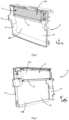
- FIGS. 2 and 3 illustrate respectively in front view and in rear view the cooling device 11 according to an embodiment of the invention.
- the second heat exchanger 9 is masked in these figures so as to make the first heat exchanger 6 clearly visible.
- the first heat exchanger 6 and the second heat exchanger 9 both extend parallel to a plane perpendicular to the longitudinal axis X.
- the first heat exchanger 6 is positioned behind the second heat exchanger 9.
- An air gap can separate the first heat exchanger 6 of the second heat exchanger 9.
- the cooling device also comprises an air guide 12.
- the air guide 12 comprises a frame 13 arranged around the first heat exchanger 6 and the second heat exchanger 9.
- the frame 13 comprises a central opening 14 inside which the first heat exchanger 6 and the second heat exchanger 9 are housed. More particularly, the air guide 12 has a generally rectangular external shape. It extends generally in a plane perpendicular to the longitudinal axis X.
- the air guide further comprises at least one transverse bar 15 extending parallel to the transverse axis Y. The transverse bar therefore passes through the central opening 14 and separates it into at least two secondary openings 14A, 14B.
- a first secondary opening 14A is arranged above a second secondary opening 14B along the Z axis.
- the air guide matches the shape of the second heat exchanger, that is to say that the second heat exchanger occupies substantially the entire central opening 14.
- the transverse bar 15 is positioned just below the first heat exchanger 6.
- the first heat exchanger could be positioned at the bottom of the air guide 12 and occupy the secondary opening 14B.
- the air guide 12 could comprise two transverse bars and the first heat exchanger would then be positioned halfway up the air guide, between these two transverse bars.
- the air guide delimits the outer contour of the cooling device 11. It also allows the two heat exchangers 6 and 9 to be protected laterally.
- the air guide allows an air flow to be guided towards the two heat exchangers by preventing the air from escaping to the sides. In other words, it allows the air flow to be channeled so as to force the air to pass through the two heat exchangers 6 and 9.
- the air guide comprises walls which extend parallel to the longitudinal axis X.
- the length of the air guide along the longitudinal axis X can be of the order of magnitude of the length of the superposition of the two heat exchangers 6 and 9 along the longitudinal axis X.
- the length of the air guide can also be greater than the superposition of the two heat exchangers 6 and 9 along the longitudinal axis X, because it is often intended to guide the air from an air intake which is at the front of the vehicle.
- the first radiator or heat exchanger in our case, is housed in the air guide in order to avoid leaks on the sides after the passage of its bundle, the air guide arriving at the level of the bundle of the second radiator or heat exchanger to be crossed by the air. It is not necessary to extend the air guide along the longitudinal axis X substantially beyond the level of the bundle of the second exchanger.
- the thickness of the walls constituting the air guide can be of the order of a few millimeters.
- the air passage section can be maximized.
- a compromise can be made at the level of the bar consisting of ribbing it so as to create gaps allowing the passage of as much air as possible along the longitudinal axis X. This also makes it possible to lighten the air guide.
- the air guide can be manufactured from a single- or dual-material plastic material.
- the air guide can be a single-piece element, for example obtained by plastic injection. Alternatively, it could for example be manufactured from sheet metal or any other material comprising equivalent mass and/or rigidity characteristics.
- the first heat exchanger 6 is also clearly visible on the Figure 4 in which the second heat exchanger 9 is still hidden.
- the first heat exchanger 6 comprises a body 16 capable of being crossed by an air flow, a first fixing interface 17, a second fixing interface 18, and a housing 19.
- the housing 19 is equipped with a thermostat 20, an inlet duct 21 and an outlet duct 22.
- the body 16 is a part of the heat exchanger intended to be cooled by an air flow. It may be provided with channels in which the oil circulates.
- the body 16 has a generally rectangular shape extending perpendicular to the longitudinal axis X.
- the body 16 therefore comprises four sides, two sides of which extend parallel to the transverse axis Y and two sides extend parallel to the axis Z.
- the dimension of the body 16 in the plane perpendicular to the longitudinal axis X may be substantially equal to the dimension of the secondary opening 14A. In other words, the body 16 occupies substantially the entire width of the opening 14A of the air guide.
- the body 16 may be equipped with fins and/or a honeycomb structure and/or any other structure making it possible to increase a heat exchange surface with the air circulating along the body 16.
- the housing 19 is attached to the body 16 and rigidly fixed thereto.
- the housing 19 is positioned next to the first fixing interface 17. It may have a generally parallelepiped shape.
- the housing 19 contains the thermostat 20, i.e. a valve whose fluid flow rate passing through it can be adjusted as a function of a temperature. The thermostat therefore makes it possible to regulate the quantity of oil circulating inside the body 16. Internal conduits in the first heat exchanger therefore make it possible to connect the housing 19 to the body 16.
- the inlet duct 21 extends from the housing 19 substantially parallel to the transverse axis Y.
- the outlet duct 22 also extends from the housing 19, substantially parallel to the axis Z.
- the inlet duct and the outlet duct are in the form of a generally cylindrical tube.
- the orientation of these two ducts could be reversed, that is to say that the inlet duct would extend substantially parallel to the axis Z and the outlet duct would extend substantially parallel to the transverse axis Y.
- the inlet duct and the outlet duct therefore preferably extend in mutually perpendicular directions. These directions are both perpendicular to the longitudinal axis X.
- the two ducts 21, 22 could each extend in any other direction.
- the body 16 and the housing 19 may be made of metal and rigidly fixed together.
- the body 16 and the housing 19 may be generally non-deformable compared to a plastic material.
- the housing 19 comprising the thermostat 20 may be the most rigid part of the first heat exchanger.
- the two fixing interfaces 17, 18 connect the first heat exchanger 6 to the air guide 12.
- the two fixing interfaces 17, 18 can be fixed to an upper edge of the frame 13 of the air guide 12 and to the transverse bar 15.
- the first heat exchanger is therefore fixed directly to the air guide 12 via its two fixing interfaces 17, 18.
- the first heat exchanger 6 is not fixed directly to the second heat exchanger 9.
- the first heat exchanger 6 and the second heat exchanger 9 are not in contact with each other.
- the two fixing interfaces 17, 18 are arranged respectively along two opposite sides of the body.
- the two opposite sides of the body on which the fixing interfaces 17, 18 are arranged are sides extending parallel to the Z axis.
- the heat exchanger may comprise two manifolds extending parallel to the Z axis on either side of the body 16.
- the manifolds are buffer volumes in which the heat transfer fluid can be stored before circulating through the channels arranged in the body 16.
- the two fixing interfaces 17, 18 may cover these manifolds and extend over the entire height of the body 16.
- opposite sides we preferably mean two parallel sides. More preferably, the opposite sides are not adjacent.
- the first heat exchanger is fixed exclusively by the first and second interfaces.
- the two fixing interfaces 17, 18 are made of plastic.
- the use of plastic gives the fixing interfaces a certain flexibility which can be useful for compensating for thermal expansions and/or dispersions linked to the manufacture of elements of the cooling device.
- the fixing interfaces are overmolded on the two opposite sides of the body, in particular overmolded respectively on the two manifolds of the body.
- the fixing interfaces could be in the form of half-shells fixed together, in particular clipped together around the two opposite sides of the body.
- the fixing interfaces 17, 18 are made directly with the manifolds in the sense that they come respectively from the material of one of the manifolds of the first heat exchanger 6, which is then made by molding a plastic material.
- the fixing interfaces are firmly retained on the body 16.
- the fixing interfaces do not cover the housing 19. They also do not cover the useful surface of the body 16, i.e. the surface of the body 16 extending perpendicular to the longitudinal axis X and intended to receive an air flow.
- the fixing interfaces do not reduce not the useful surface area of the body 16. They also do not reduce the useful surface area of a body of the second heat exchanger 9.
- the fixing interfaces 17, 18 may be at least globally identical or symmetrical. They each comprise a first fixing means 23 and a second fixing means 24.
- the first fixing means 23 is arranged at the top of each fixing interface 17, 18 and it cooperates with the upper edge 25 of the frame 13 of the air guide 12.
- the second fixing means 24 is arranged at the bottom of each fixing interface 17, 18 and it cooperates with the transverse bar 15 of the air guide 12.
- the fixing means 23, 24 are produced by holes capable of cooperating with fixing screws 26.
- these fixing means could be produced for example with clips.
- the second heat exchanger 9, not shown, may also comprise a body extending perpendicular to the longitudinal axis and capable of being traversed by an air flow. This body may then extend over the entire surface of the main opening 14.
- the useful surface area of the body of the second heat exchanger i.e. the surface area of the body of the second heat exchanger which receives an air flow (the surface area perpendicular to the longitudinal axis X), is greater than the useful surface area of the body of the first heat exchanger.
- the entire air flow passing through the body of the first heat exchanger has previously passed through the body of the second heat exchanger.
- a portion of the air flow passing through the body of the second heat exchanger does not pass through the body of the first heat exchanger.
- the second heat exchanger 9 may also be fixed to the air guide 12.
- FIG. 5 illustrates in more detail a feature of the cooling device, in particular the interface between the housing 19 and the air guide 12.
- the air guide 12 comprises a first chamber 27 in which the inlet duct 21 is arranged, and a second chamber 28 in which the outlet duct 22 is arranged.
- the two chambers are integrated into the frame 13 of the air guide 12, in particular at the level of an upper part of a lateral edge of the frame. In particular, they are arranged in a lateral edge of the air guide opposite the first heat exchanger 6.
- the first chamber 27 comprises walls 29 substantially parallel to the longitudinal axis X.
- the second chamber comprises walls 30 substantially parallel to the longitudinal axis X.
- the two chambers 27, 28 are positioned side by side.
- a wall 31 is common to both the first chamber and the second chamber.
- the first chamber 27 and the second chamber 28 respectively isolate the inlet duct 21 and the outlet duct 22 from the housing 19.
- the walls 29, 30, 31 form ribs and thus contribute to the overall rigidity of the air guide 12.
- the air guide comprises a first slot 32 through which the inlet duct passes.
- This slot 32 is arranged in one of the walls 29 forming the first chamber, in particular a wall extending perpendicular to the axis in which the inlet duct extends.
- the air guide comprises a second slot 33 through which the outlet duct passes.
- This second slot 33 is arranged in one of the walls 30 forming the second chamber, in particular a wall extending perpendicular to the axis in which the outlet duct extends.
- the first slot 32 and the second slot 33 are also clearly visible on the Figure 6 . They may have a generally identical shape.
- the two slots 32, 33 may open towards the rear of the air guide.
- the two slots may have a generally keyhole shape.
- the inlet duct and the outlet duct are positioned at the bottom of their respective slot, in the wider portions 35.
- the sealing device further comprises a first sealing element 36 made of flexible and/or elastic material, arranged at the interface between the first slot and the inlet duct.
- the sealing device comprises a second sealing element 37 made of flexible material, arranged at the interface between the second slot and the outlet duct.
- the first sealing element and/or the second sealing element may be made, for example, of rubber or foam. They are sufficiently flexible to deform and allow the inlet and outlet ducts to pass along the narrow portions 34 of each slot when assembling the first heat exchanger to the air guide.
- the sealing elements make it possible to fill a gap existing between the edges of each slot 32, 33 and the respective ducts. They therefore prevent an air flow from escaping through the slots 32, 33. The air flow thus remains concentrated towards the housing 19 and the body 16.
- the slots 32, 33 could not be equipped with the sealing elements 36, 37 if air leaks through the slots are acceptable.
- the inlet duct 21 When the inlet duct 21 is in place in the first slot 32, it can only move slightly parallel to the Z axis thanks to the elasticity of the first sealing element 36.
- the positioning of the inlet duct 21 in the first slot 32 does not in itself define the position of the first heat exchanger 6 relative to the air guide 12 along the Z axis.
- the position of the first heat exchanger 6 along the Z axis can be defined by a support of the thermostat body, in particular on the axis of the screw in the upper left part.
- the outlet duct 22 when the outlet duct 22 is in place in the second slot 33, it can only slightly move parallel to the transverse axis Y thanks to the elasticity of the second sealing element 37.
- the positioning of the outlet duct 22 in the second slot 33 does not alone therefore define the position of the first heat exchanger 6 relative to the air guide 12 along the transverse axis Y.
- the position of the first heat exchanger 6 along the Y axis can be defined by a support of the thermostat body.
- the position along the transverse axis Y can be limited on the other side by the side of the elastic clip in the upper part of the thermostat.
- the two slots 32, 33 do not constitute a means of positioning the housing, but serve to extract the inlet and outlet ducts towards the air chambers external to the air guide.
- the two slots 32, 33 do not prevent a translational movement of the first heat exchanger 6 relative to the air guide 12 along the longitudinal axis X.
- the reaction force of the narrow portions 34 on the ducts 21 and 22 generates an increase in the force necessary to engage or disengage the first heat exchanger 6 against the air guide 12.
- the position of the first heat exchanger relative to the air guide along the longitudinal axis X is defined by the cooperation of the fixing means 23, 24 with the frame of the air guide and the fixing screws 26.
- the fixing means 23, 24 are made by oblong holes 38.
- the oblong holes 38 have the shape of an oval oriented parallel to the transverse axis Y. They are positioned substantially opposite a circular hole 39 provided in the air guide 12. The use of such oblong holes therefore allows the fixing interfaces 17, 18 to move relative to the air guide parallel to the transverse axis Y. This makes it possible to compensate for a certain dispersion resulting from the manufacture of the components of the cooling device and/or relative movements linked to the thermal expansion of components of the cooling device.
- the height of the oblong holes 38 in the lower part along the Z axis can also be greater than the diameter of the circular holes 39 to allow in the same way a relative movement between the heat exchanger 6 and the air guide 12 along the Z axis.
- the height along the Z axis of the oblong hole of axis Y positioned at the bottom of the fixing interfaces 17 and 18 is greater than the diameter of the circular hole 39 in the air guide.
- the thickness and/or the rigidity of the plastic materials forming the air guide (in particular the walls supporting the slots 32, 33) and the fixing interfaces 17, 18 can also confer a certain mobility of the first heat exchanger relative to the air guide.
- the oblong holes are arranged in upper and lower appendages 40 of each fixing interface 17, 18. These appendages may have a generally rectangular shape extending perpendicular to the longitudinal axis X.
- the upper appendage 40 of the fixing interface 18, or even the upper appendage 40 of the fixing interface 17, may be surmounted by a rim 41 capable of bearing vertically on an edge of the air guide in order to support the weight of the body 16 and to ensure a positioning along the Z axis.
- the fixing screws 26 do not support the weight of the body 16 or the housing 19 but only serve for the longitudinal fixing of the first heat exchanger.
- the rim 41 can help to position the first heat exchanger 6 relative to the air guide 12 during their assembly.
- the fixing screws 26 are screws suitable for soft materials such as plastic.
- the fixing screws 26 may comprise a pointed end and wide threads to fit well into the plastic material forming the air guide.
- the first heat exchanger is therefore fixed to the air guide without any degree of freedom relative to the longitudinal axis X.
- the air guide further comprises an elastic support means 42 exerting a downward force on the housing 19 so that the left side of the air guide serves as a reference for stopping the cooler in its Y movement, in particular to the right.
- the support means may be in the form of a flexible tab, or blade, made of the same material as that forming the air guide 12.
- the support means 42 exerts a force on the housing 19 which contributes to its good holding against the air guide 12 without however preventing any relative movement between the air guide and the first heat exchanger 6.
- other equivalent support means could be used to generate a stress on the first heat exchanger parallel to the transverse axis Y or parallel to the longitudinal axis X.
- an air guide 12 can first be manufactured. This can be manufactured, for example, by plastic injection.
- a first exchanger can be manufactured. heat exchanger and a second heat exchanger.
- the housing 19 can be assembled to the body 16 and then the two lateral edges of the body 16 can be overmolded to form the two fixing interfaces.
- the two lateral edges of the body 16 could be overmolded beforehand to form the two fixing interfaces and then the body 16 could be assembled to the housing 19.
- the first heat exchanger 6 can be positioned relative to the air guide 12. The first heat exchanger is inserted parallel to the longitudinal axis X in the air guide 12.
- the correct positioning of the first heat exchanger relative to the air guide is obtained by positioning the housing 19 of the first heat exchanger relative to the air guide.
- the housing 19 forming the most rigid part of the first heat exchanger, it is preferable to first fix the position of the housing 19 then of the body 16 because the body 16 will be able to deform slightly more easily to adjust its position relative to the air guide 12.
- the correct positioning of the housing 19 relative to the air guide can be obtained when the inlet ducts 21 and the outlet duct 22 are positioned respectively in the wider portions 35 of the slots 32 and 33.
- This positioning of the housing 19 can be obtained during the Y-shaped supports on the sides of the thermostat and in Z-shaped supports at the bottom of the thermostat, so that this positioning is immobilized while waiting for the screws, by the elastic blade located in the upper part against the body of the thermostat. It is essential that there is no transmitted force or friction in the ducts, because they are fixed by aluminum-aluminum welding to the housing and their thickness generally does not exceed one millimeter. The presence of the thermostat, a solid piece of aluminum, made it possible to avoid placing additional constraints on the fixing screws for soft materials.
- the fixing screws 26 be screwed through the oblong holes 38 of the fixing interfaces 17, 18 and through the holes circular 39 of the air guide 12, which will have the effect of freezing the position of the first heat exchanger along the longitudinal axis X, but also along the vertical axis Z in the upper part on the left side, or even along the vertical axis Z in the upper part on the right side, by being equipped with a force recovery lug so as to only make the screws work along the longitudinal axis X.
- the air guide 12 can be fixed to the second heat exchanger 9.
- the second heat exchanger can be assembled to the body by a filtration means, in particular via filter pads in the upper and lower part of this exchanger.
- the mounting of the cooling device 11 can optionally be completed by fixing other peripherals, for example a fan, against one of the heat exchangers 6, 9 and/or against the air guide 12.
- the first heat exchanger could not include the housing 19.
- the inlet and outlet ducts would then be arranged directly on one of the two manifolds. In this case, it is the manifold carrying the inlet and outlet duct which would position the air guide.
- the cooling device is preferably fixed to the body using filter pads in the upper and lower parts.
- the air flow generated by the movement of the vehicle 1 successively passes through the first heat exchanger 6 then the second heat exchanger 9, or vice versa.
- the air cools in a limited manner the body 19 which is a solid aluminum body machined so as to receive all of the components making it possible to open and close the circulation of the liquid through the bundle 16. If thermal expansions occur on the set of coolers 6 and 9, the relative positions of the exchangers 6, 9 and the air guide can vary without creating mechanical stress in these components.
- the efficiency of the first heat exchanger is optimal because its fixing interfaces do not reduce its useful surface area.
- the air flow is guided towards the body of each of the heat exchangers, which allows the heat transfer fluids circulating inside these bodies to be efficiently cooled.
Landscapes
- Engineering & Computer Science (AREA)
- Mechanical Engineering (AREA)
- General Engineering & Computer Science (AREA)
- Chemical & Material Sciences (AREA)
- Combustion & Propulsion (AREA)
- Cooling, Air Intake And Gas Exhaust, And Fuel Tank Arrangements In Propulsion Units (AREA)
- Details Of Measuring And Other Instruments (AREA)
Claims (11)
- Kühlvorrichtung (11) für ein Kraftfahrzeug (1), beinhaltend:- einen ersten Wärmetauscher (6) und- eine Luftführung (12), die einen Rahmen (13) beinhaltet, der den ersten Wärmetauscher (6) umgibt,wobei der erste Wärmetauscher (6) Folgendes beinhaltet:- einen Körper (16), der dazu fähig ist, von einem Luftstrom durchquert zu werden, und- eine erste Befestigungsschnittstelle (17), die entlang einer ersten Seite des Körpers (16) eingerichtet ist,- eine zweite Befestigungsschnittstelle (18), die entlang einer zweiten Seite des Körpers (16) eingerichtet ist, wobei die zweite Seite der ersten Seite entgegengesetzt ist,wobei der erste Wärmetauscher (6) durch die zwei Befestigungsschnittstellen (17, 18) an der Luftführung (12) befestigt ist,dadurch gekennzeichnet, dass er ferner ein Gehäuse (19) beinhaltet, das mit einem Thermostaten (20), einer Eingangsleitung (21) und einer Ausgangsleitung (22) ausgerüstet ist, wobei die Kühlvorrichtung (11) ein Mittel zum Positionieren des Gehäuses (19) in Bezug auf die Luftführung (12) beinhaltet.
- Kühlvorrichtung (11) nach dem vorhergehenden Anspruch, dadurch gekennzeichnet, dass die erste Befestigungsschnittstelle (17) ein Kunststoffmaterial beinhaltet, das auf die erste Seite des Körpers (16) aufgeformt ist, und/oder dass die zweite Befestigungsschnittstelle (18) ein Kunststoffmaterial beinhaltet, das auf die zweite Seite des Körpers (16) aufgeformt ist.
- Kühlvorrichtung (11) nach einem der vorhergehenden Ansprüche, dadurch gekennzeichnet, dass der erste Wärmetauscher (6) eine erste Sammlerkammer entlang der ersten Seite des Körpers (16) und eine zweite Sammlerkammer entlang der zweiten Seite des Körpers (16) beinhaltet, wobei die erste Befestigungsschnittstelle (17) auf die erste Sammlerkammer aufgeformt ist und/oder die zweite Befestigungsschnittstelle (18) auf die zweite Sammlerkammer aufgeformt ist.
- Kühlvorrichtung (11) nach einem der vorhergehenden Ansprüche, dadurch gekennzeichnet, dass der erste Wärmetauscher (6) eine Eingangsleitung (21) und eine Ausgangsleitung (22) beinhaltet, wobei die Eingangsleitung (21) in einem ersten Spalt (32), der in einer Wand der Luftführung (12) eingerichtet ist, positioniert ist und/oder die Ausgangsleitung (22) in einem zweiten Spalt (3), der in einer Wand der Luftführung (12) eingerichtet ist, positioniert ist.
- Kühlvorrichtung (11) nach dem vorhergehenden Anspruch, dadurch gekennzeichnet, dass sie ein erstes Dichtungselement (36) aus flexiblem Material, insbesondere aus Gummi oder Schaumstoff, beinhaltet, wobei das erste Dichtungselement (36) an der Schnittstelle zwischen dem ersten Spalt (32) und der Eingangsleitung (21) eingerichtet ist, und/oder dass sie ein zweites Dichtungselement (37) aus flexiblem Material, insbesondere aus Gummi oder Schaumstoff, beinhaltet, wobei das zweite Dichtungselement an der Schnittstelle zwischen dem zweiten Spalt (33) und der Ausgangsleitung (22) eingerichtet ist.
- Kühlvorrichtung (11) nach einem der vorhergehenden Ansprüche, dadurch gekennzeichnet, dass sich der erste Wärmetauscher (6) im Wesentlichen in einer Ebene erstreckt, wobei der erste Wärmetauscher (6) mit Spiel an der Luftführung (12) befestigt ist, sodass er sich parallel zu der Ebene bewegen kann, und/oder wobei der erste Wärmetauscher (6) so an der Luftführung (12) befestigt ist, dass er senkrecht zu der Ebene unbeweglich ist.
- Kühlvorrichtung (11) nach einem der vorhergehenden Ansprüche, dadurch gekennzeichnet, dass:- die Luftführung (12) eine zentrale Öffnung (14) beinhaltet und der erste Wärmetauscher (6) eine Breite, die im Wesentlichen gleich der Breite der zentralen Öffnung (14) ist, und eine Höhe, die strikt kleiner als die Höhe der zentralen Öffnung (14) ist, beinhaltet,und/oder dadurch gekennzeichnet, dass:- die Luftführung eine Querstrebe (15) beinhaltet, die zwei individuelle Öffnungen (14A, 14B) der Luftführung begrenzt, wobei jede der zwei Öffnungen dazu fähig ist, von einem Luftstrom durchquert zu werden, wobei die zwei Befestigungsschnittstellen (17, 18) des ersten Wärmetauschers (6) an der Querstrebe (15) befestigt sind.
- Kühlvorrichtung (11) nach einem der vorhergehenden Ansprüche, dadurch gekennzeichnet, dass sie einen zweiten Wärmetauscher (9) beinhaltet, der sich im Wesentlichen parallel zu dem ersten Wärmetauscher (6) erstreckt, wobei die Luftführung (12) an die Kontur des zweiten Wärmetauschers (9) angepasst ist.
- Kraftfahrzeug (1), dadurch gekennzeichnet, dass es eine Kühlvorrichtung (11) nach einem der vorhergehenden Ansprüche umfasst.
- Verfahren zur Herstellung einer Kühlvorrichtung (11) nach einem der Ansprüche 1 bis 8, dadurch gekennzeichnet, dass es Folgendes beinhaltet:- einen Schritt des Positionierens des ersten Wärmetauschers (6) in Bezug auf die Luftführung (12), wobei das Positionieren des ersten Wärmetauschers (6) in Bezug auf die Luftführung (12) dadurch bestimmt wird, dass ein Gehäuse (19) des ersten Wärmetauschers (6) in Bezug auf die Luftführung (12) positioniert wird, wobei das Gehäuse (19) mit einem Thermostaten (20) und/oder einer Eingangsleitung (21) und/oder einer Ausgangsleitung (22) ausgerüstet ist, dann- einen Schritt des Befestigens des ersten Wärmetauschers (6) an der Luftführung (12) mit Hilfe der zwei Befestigungsschnittstellen (17, 18).
- Verfahren zur Herstellung einer Kühlvorrichtung (11) nach dem vorhergehenden Anspruch, dadurch gekennzeichnet, dass es anschließend einen Schritt des Befestigens der Luftführung (12) an einem zweiten Wärmetauscher (9) beinhaltet.
Applications Claiming Priority (2)
| Application Number | Priority Date | Filing Date | Title |
|---|---|---|---|
| FR2000099A FR3105982B1 (fr) | 2020-01-07 | 2020-01-07 | Dispositif de refroidissement pour véhicule automobile |
| PCT/EP2020/086406 WO2021139980A1 (fr) | 2020-01-07 | 2020-12-16 | Dispositif de refroidissement pour véhicule automobile |
Publications (2)
| Publication Number | Publication Date |
|---|---|
| EP4088014A1 EP4088014A1 (de) | 2022-11-16 |
| EP4088014B1 true EP4088014B1 (de) | 2025-05-14 |
Family
ID=69903620
Family Applications (1)
| Application Number | Title | Priority Date | Filing Date |
|---|---|---|---|
| EP20828296.2A Active EP4088014B1 (de) | 2020-01-07 | 2020-12-16 | Kühlvorrichtung für ein kraftfahrzeug |
Country Status (4)
| Country | Link |
|---|---|
| EP (1) | EP4088014B1 (de) |
| KR (1) | KR20220121882A (de) |
| FR (1) | FR3105982B1 (de) |
| WO (1) | WO2021139980A1 (de) |
Family Cites Families (6)
| Publication number | Priority date | Publication date | Assignee | Title |
|---|---|---|---|---|
| DE3112202C2 (de) * | 1981-03-27 | 1984-11-15 | Bayerische Motoren Werke Ag, 8000 Muenchen | Kühlvorrichtung für flüssigkeitsgekühlte Brennkraftmaschinen |
| DE9213450U1 (de) * | 1992-10-06 | 1993-01-07 | Cummins Engine Co. Ltd., New Malden, Surrey | Antriebseinheit |
| DE10344219A1 (de) * | 2003-09-22 | 2005-04-14 | Behr Gmbh & Co. Kg | Wärmeübertragermodul für ein Kraftfahrzeug |
| US20090159239A1 (en) * | 2007-12-22 | 2009-06-25 | Sameer Desai | Vehicle heat exchanger and method for selectively controlling functions |
| DE102009056508A1 (de) * | 2009-12-02 | 2011-06-09 | Behr Gmbh & Co. Kg | Kühlmodul und Adapterpaar für Modulvereinheitlichung |
| FR3070321B1 (fr) * | 2017-08-29 | 2020-07-17 | Valeo Systemes Thermiques | Unite de refroidissement pour un compartiment d'un vehicule automobile |
-
2020
- 2020-01-07 FR FR2000099A patent/FR3105982B1/fr active Active
- 2020-12-16 EP EP20828296.2A patent/EP4088014B1/de active Active
- 2020-12-16 KR KR1020227027296A patent/KR20220121882A/ko active Pending
- 2020-12-16 WO PCT/EP2020/086406 patent/WO2021139980A1/fr not_active Ceased
Also Published As
| Publication number | Publication date |
|---|---|
| FR3105982B1 (fr) | 2022-03-25 |
| FR3105982A1 (fr) | 2021-07-09 |
| EP4088014A1 (de) | 2022-11-16 |
| KR20220121882A (ko) | 2022-09-01 |
| WO2021139980A1 (fr) | 2021-07-15 |
Similar Documents
| Publication | Publication Date | Title |
|---|---|---|
| EP1120620A1 (de) | Wärmeaustauschmodul, insbesondere für Kraftfahrzeuge | |
| EP4072883B1 (de) | Kühlmodul für ein kraftfahrzeug | |
| WO2004005830A2 (fr) | Dispositif de support d'echangeurs de chaleur et module d'echange de chaleur associe | |
| EP0183596A1 (de) | Kühlfluidumkühlvorrichtung einer Brennkraftmaschine | |
| EP1456596B1 (de) | Verbesserte anordnung zur instandhaltung einer kraftfahrzeugausrüstung und schutz der ausrüstung bei einem aufprall | |
| WO2012159777A1 (fr) | Echangeur thermique, notamment pour vehicule automobile, et dispositif d'admission d'air correspondant | |
| EP4088014B1 (de) | Kühlvorrichtung für ein kraftfahrzeug | |
| FR2703957A1 (fr) | Ensemble de radiateurs de refroidissement et dispositif de fixation pour celui-ci. | |
| WO2020160885A1 (fr) | Agencement d'un compartiment moteur d'un véhicule automobile | |
| EP3931018B1 (de) | Multifunktionshalterung für eine wärmekraftmaschine | |
| WO2019002728A1 (fr) | Unité de refroidissement pour compartiment moteur | |
| WO2018134491A1 (fr) | Dispositif d'obturation d'entree d'air de face avant de vehicule automobile et procede de fabrication | |
| EP3194195B1 (de) | Kühlanordnung für eine zu kühlende einheit, umfassend einen kühler und eine ventilatorhalterung | |
| FR3061877A1 (fr) | Dispositif d’obturation d’entree d’air de face avant de vehicule automobile et procede de fabrication | |
| FR2822941A1 (fr) | Module d'echange de chaleur a montage simplifie pour vehicule automobile | |
| FR2800862A1 (fr) | Radiateur de fluide de refroidissement comportant un reservoir de compensation | |
| FR2726074A1 (fr) | Dispositif d'assemblage entre deux echangeurs de chaleur adjacents | |
| FR3089000A1 (fr) | Agencement d’un échangeur de chaleur | |
| FR2841974A1 (fr) | Equipement et procede de montage d'un echangeur de chaleur, notamment pour vehicule automobile | |
| WO2018134493A1 (fr) | Dispositif d'obturation d'entree d'air de face avant de vehicule automobile | |
| FR3160458A1 (fr) | Echangeur de chaleur configuré pour être monté sur un cadre | |
| FR2933044A3 (fr) | Dispositif d'admission d'air pour vehicule automobile | |
| WO2021014090A1 (fr) | Dispositif de fermeture et module de refroidissement pour vehicule automobile | |
| WO2022242957A1 (fr) | Module thermique pour vehicule automobile | |
| FR3114047A1 (fr) | Module d’échange thermique et véhicule automobile correspondant |
Legal Events
| Date | Code | Title | Description |
|---|---|---|---|
| STAA | Information on the status of an ep patent application or granted ep patent |
Free format text: STATUS: UNKNOWN |
|
| STAA | Information on the status of an ep patent application or granted ep patent |
Free format text: STATUS: THE INTERNATIONAL PUBLICATION HAS BEEN MADE |
|
| PUAI | Public reference made under article 153(3) epc to a published international application that has entered the european phase |
Free format text: ORIGINAL CODE: 0009012 |
|
| STAA | Information on the status of an ep patent application or granted ep patent |
Free format text: STATUS: REQUEST FOR EXAMINATION WAS MADE |
|
| 17P | Request for examination filed |
Effective date: 20220704 |
|
| AK | Designated contracting states |
Kind code of ref document: A1 Designated state(s): AL AT BE BG CH CY CZ DE DK EE ES FI FR GB GR HR HU IE IS IT LI LT LU LV MC MK MT NL NO PL PT RO RS SE SI SK SM TR |
|
| DAV | Request for validation of the european patent (deleted) | ||
| DAX | Request for extension of the european patent (deleted) | ||
| GRAP | Despatch of communication of intention to grant a patent |
Free format text: ORIGINAL CODE: EPIDOSNIGR1 |
|
| STAA | Information on the status of an ep patent application or granted ep patent |
Free format text: STATUS: GRANT OF PATENT IS INTENDED |
|
| INTG | Intention to grant announced |
Effective date: 20241211 |
|
| GRAS | Grant fee paid |
Free format text: ORIGINAL CODE: EPIDOSNIGR3 |
|
| GRAA | (expected) grant |
Free format text: ORIGINAL CODE: 0009210 |
|
| STAA | Information on the status of an ep patent application or granted ep patent |
Free format text: STATUS: THE PATENT HAS BEEN GRANTED |
|
| AK | Designated contracting states |
Kind code of ref document: B1 Designated state(s): AL AT BE BG CH CY CZ DE DK EE ES FI FR GB GR HR HU IE IS IT LI LT LU LV MC MK MT NL NO PL PT RO RS SE SI SK SM TR |
|
| REG | Reference to a national code |
Ref country code: GB Ref legal event code: FG4D Free format text: NOT ENGLISH |
|
| REG | Reference to a national code |
Ref country code: CH Ref legal event code: EP |
|
| REG | Reference to a national code |
Ref country code: IE Ref legal event code: FG4D Free format text: LANGUAGE OF EP DOCUMENT: FRENCH |
|
| REG | Reference to a national code |
Ref country code: DE Ref legal event code: R096 Ref document number: 602020051358 Country of ref document: DE |
|
| REG | Reference to a national code |
Ref country code: NL Ref legal event code: MP Effective date: 20250514 |
|
| PG25 | Lapsed in a contracting state [announced via postgrant information from national office to epo] |
Ref country code: PT Free format text: LAPSE BECAUSE OF FAILURE TO SUBMIT A TRANSLATION OF THE DESCRIPTION OR TO PAY THE FEE WITHIN THE PRESCRIBED TIME-LIMIT Effective date: 20250915 Ref country code: FI Free format text: LAPSE BECAUSE OF FAILURE TO SUBMIT A TRANSLATION OF THE DESCRIPTION OR TO PAY THE FEE WITHIN THE PRESCRIBED TIME-LIMIT Effective date: 20250514 Ref country code: ES Free format text: LAPSE BECAUSE OF FAILURE TO SUBMIT A TRANSLATION OF THE DESCRIPTION OR TO PAY THE FEE WITHIN THE PRESCRIBED TIME-LIMIT Effective date: 20250514 |
|
| REG | Reference to a national code |
Ref country code: LT Ref legal event code: MG9D |
|
| PG25 | Lapsed in a contracting state [announced via postgrant information from national office to epo] |
Ref country code: NO Free format text: LAPSE BECAUSE OF FAILURE TO SUBMIT A TRANSLATION OF THE DESCRIPTION OR TO PAY THE FEE WITHIN THE PRESCRIBED TIME-LIMIT Effective date: 20250814 Ref country code: GR Free format text: LAPSE BECAUSE OF FAILURE TO SUBMIT A TRANSLATION OF THE DESCRIPTION OR TO PAY THE FEE WITHIN THE PRESCRIBED TIME-LIMIT Effective date: 20250815 |
|
| PG25 | Lapsed in a contracting state [announced via postgrant information from national office to epo] |
Ref country code: NL Free format text: LAPSE BECAUSE OF FAILURE TO SUBMIT A TRANSLATION OF THE DESCRIPTION OR TO PAY THE FEE WITHIN THE PRESCRIBED TIME-LIMIT Effective date: 20250514 Ref country code: PL Free format text: LAPSE BECAUSE OF FAILURE TO SUBMIT A TRANSLATION OF THE DESCRIPTION OR TO PAY THE FEE WITHIN THE PRESCRIBED TIME-LIMIT Effective date: 20250514 |
|
| REG | Reference to a national code |
Ref country code: AT Ref legal event code: MK05 Ref document number: 1794936 Country of ref document: AT Kind code of ref document: T Effective date: 20250514 |
|
| PG25 | Lapsed in a contracting state [announced via postgrant information from national office to epo] |
Ref country code: BG Free format text: LAPSE BECAUSE OF FAILURE TO SUBMIT A TRANSLATION OF THE DESCRIPTION OR TO PAY THE FEE WITHIN THE PRESCRIBED TIME-LIMIT Effective date: 20250514 |
|
| PG25 | Lapsed in a contracting state [announced via postgrant information from national office to epo] |
Ref country code: HR Free format text: LAPSE BECAUSE OF FAILURE TO SUBMIT A TRANSLATION OF THE DESCRIPTION OR TO PAY THE FEE WITHIN THE PRESCRIBED TIME-LIMIT Effective date: 20250514 |
|
| PG25 | Lapsed in a contracting state [announced via postgrant information from national office to epo] |
Ref country code: AT Free format text: LAPSE BECAUSE OF FAILURE TO SUBMIT A TRANSLATION OF THE DESCRIPTION OR TO PAY THE FEE WITHIN THE PRESCRIBED TIME-LIMIT Effective date: 20250514 |
|
| PG25 | Lapsed in a contracting state [announced via postgrant information from national office to epo] |
Ref country code: RS Free format text: LAPSE BECAUSE OF FAILURE TO SUBMIT A TRANSLATION OF THE DESCRIPTION OR TO PAY THE FEE WITHIN THE PRESCRIBED TIME-LIMIT Effective date: 20250814 |
|
| PG25 | Lapsed in a contracting state [announced via postgrant information from national office to epo] |
Ref country code: IS Free format text: LAPSE BECAUSE OF FAILURE TO SUBMIT A TRANSLATION OF THE DESCRIPTION OR TO PAY THE FEE WITHIN THE PRESCRIBED TIME-LIMIT Effective date: 20250914 |
|
| PG25 | Lapsed in a contracting state [announced via postgrant information from national office to epo] |
Ref country code: LV Free format text: LAPSE BECAUSE OF FAILURE TO SUBMIT A TRANSLATION OF THE DESCRIPTION OR TO PAY THE FEE WITHIN THE PRESCRIBED TIME-LIMIT Effective date: 20250514 |
|
| PGFP | Annual fee paid to national office [announced via postgrant information from national office to epo] |
Ref country code: DE Payment date: 20251211 Year of fee payment: 6 |
|
| PGFP | Annual fee paid to national office [announced via postgrant information from national office to epo] |
Ref country code: GB Payment date: 20251219 Year of fee payment: 6 |
|
| PG25 | Lapsed in a contracting state [announced via postgrant information from national office to epo] |
Ref country code: DK Free format text: LAPSE BECAUSE OF FAILURE TO SUBMIT A TRANSLATION OF THE DESCRIPTION OR TO PAY THE FEE WITHIN THE PRESCRIBED TIME-LIMIT Effective date: 20250514 Ref country code: SM Free format text: LAPSE BECAUSE OF FAILURE TO SUBMIT A TRANSLATION OF THE DESCRIPTION OR TO PAY THE FEE WITHIN THE PRESCRIBED TIME-LIMIT Effective date: 20250514 |
|
| PGFP | Annual fee paid to national office [announced via postgrant information from national office to epo] |
Ref country code: FR Payment date: 20251229 Year of fee payment: 6 |
|
| PG25 | Lapsed in a contracting state [announced via postgrant information from national office to epo] |
Ref country code: CZ Free format text: LAPSE BECAUSE OF FAILURE TO SUBMIT A TRANSLATION OF THE DESCRIPTION OR TO PAY THE FEE WITHIN THE PRESCRIBED TIME-LIMIT Effective date: 20250514 |
|
| PG25 | Lapsed in a contracting state [announced via postgrant information from national office to epo] |
Ref country code: EE Free format text: LAPSE BECAUSE OF FAILURE TO SUBMIT A TRANSLATION OF THE DESCRIPTION OR TO PAY THE FEE WITHIN THE PRESCRIBED TIME-LIMIT Effective date: 20250514 |
|
| PG25 | Lapsed in a contracting state [announced via postgrant information from national office to epo] |
Ref country code: SK Free format text: LAPSE BECAUSE OF FAILURE TO SUBMIT A TRANSLATION OF THE DESCRIPTION OR TO PAY THE FEE WITHIN THE PRESCRIBED TIME-LIMIT Effective date: 20250514 |
|
| PG25 | Lapsed in a contracting state [announced via postgrant information from national office to epo] |
Ref country code: IT Free format text: LAPSE BECAUSE OF FAILURE TO SUBMIT A TRANSLATION OF THE DESCRIPTION OR TO PAY THE FEE WITHIN THE PRESCRIBED TIME-LIMIT Effective date: 20250514 |
|
| PG25 | Lapsed in a contracting state [announced via postgrant information from national office to epo] |
Ref country code: RO Free format text: LAPSE BECAUSE OF FAILURE TO SUBMIT A TRANSLATION OF THE DESCRIPTION OR TO PAY THE FEE WITHIN THE PRESCRIBED TIME-LIMIT Effective date: 20250514 |
|
| PLBE | No opposition filed within time limit |
Free format text: ORIGINAL CODE: 0009261 |
|
| STAA | Information on the status of an ep patent application or granted ep patent |
Free format text: STATUS: NO OPPOSITION FILED WITHIN TIME LIMIT |
|
| REG | Reference to a national code |
Ref country code: CH Ref legal event code: L10 Free format text: ST27 STATUS EVENT CODE: U-0-0-L10-L00 (AS PROVIDED BY THE NATIONAL OFFICE) Effective date: 20260325 |