EP4087095B1 - Elektrische maschine mit rotorkühlung - Google Patents
Elektrische maschine mit rotorkühlung Download PDFInfo
- Publication number
- EP4087095B1 EP4087095B1 EP22170521.3A EP22170521A EP4087095B1 EP 4087095 B1 EP4087095 B1 EP 4087095B1 EP 22170521 A EP22170521 A EP 22170521A EP 4087095 B1 EP4087095 B1 EP 4087095B1
- Authority
- EP
- European Patent Office
- Prior art keywords
- rotor
- oil
- channels
- cooling
- electric machine
- Prior art date
- Legal status (The legal status is an assumption and is not a legal conclusion. Google has not performed a legal analysis and makes no representation as to the accuracy of the status listed.)
- Active
Links
Images


Classifications
-
- H—ELECTRICITY
- H02—GENERATION; CONVERSION OR DISTRIBUTION OF ELECTRIC POWER
- H02K—DYNAMO-ELECTRIC MACHINES
- H02K1/00—Details of the magnetic circuit
- H02K1/06—Details of the magnetic circuit characterised by the shape, form or construction
- H02K1/22—Rotating parts of the magnetic circuit
- H02K1/32—Rotating parts of the magnetic circuit with channels or ducts for flow of cooling medium
-
- H—ELECTRICITY
- H02—GENERATION; CONVERSION OR DISTRIBUTION OF ELECTRIC POWER
- H02K—DYNAMO-ELECTRIC MACHINES
- H02K5/00—Casings; Enclosures; Supports
- H02K5/04—Casings or enclosures characterised by the shape, form or construction thereof
- H02K5/20—Casings or enclosures characterised by the shape, form or construction thereof with channels or ducts for flow of cooling medium
- H02K5/203—Casings or enclosures characterised by the shape, form or construction thereof with channels or ducts for flow of cooling medium specially adapted for liquids, e.g. cooling jackets
-
- H—ELECTRICITY
- H02—GENERATION; CONVERSION OR DISTRIBUTION OF ELECTRIC POWER
- H02K—DYNAMO-ELECTRIC MACHINES
- H02K1/00—Details of the magnetic circuit
- H02K1/06—Details of the magnetic circuit characterised by the shape, form or construction
- H02K1/22—Rotating parts of the magnetic circuit
- H02K1/27—Rotor cores with permanent magnets
- H02K1/2706—Inner rotors
-
- H—ELECTRICITY
- H02—GENERATION; CONVERSION OR DISTRIBUTION OF ELECTRIC POWER
- H02K—DYNAMO-ELECTRIC MACHINES
- H02K1/00—Details of the magnetic circuit
- H02K1/06—Details of the magnetic circuit characterised by the shape, form or construction
- H02K1/22—Rotating parts of the magnetic circuit
- H02K1/27—Rotor cores with permanent magnets
- H02K1/2706—Inner rotors
- H02K1/272—Inner rotors the magnetisation axis of the magnets being perpendicular to the rotor axis
- H02K1/274—Inner rotors the magnetisation axis of the magnets being perpendicular to the rotor axis the rotor consisting of two or more circumferentially positioned magnets
-
- H—ELECTRICITY
- H02—GENERATION; CONVERSION OR DISTRIBUTION OF ELECTRIC POWER
- H02K—DYNAMO-ELECTRIC MACHINES
- H02K21/00—Synchronous motors having permanent magnets; Synchronous generators having permanent magnets
- H02K21/12—Synchronous motors having permanent magnets; Synchronous generators having permanent magnets with stationary armatures and rotating magnets
- H02K21/14—Synchronous motors having permanent magnets; Synchronous generators having permanent magnets with stationary armatures and rotating magnets with magnets rotating within the armatures
-
- H—ELECTRICITY
- H02—GENERATION; CONVERSION OR DISTRIBUTION OF ELECTRIC POWER
- H02K—DYNAMO-ELECTRIC MACHINES
- H02K3/00—Details of windings
- H02K3/04—Windings characterised by the conductor shape, form or construction, e.g. with bar conductors
- H02K3/24—Windings characterised by the conductor shape, form or construction, e.g. with bar conductors with channels or ducts for cooling medium between the conductors
-
- H—ELECTRICITY
- H02—GENERATION; CONVERSION OR DISTRIBUTION OF ELECTRIC POWER
- H02K—DYNAMO-ELECTRIC MACHINES
- H02K7/00—Arrangements for handling mechanical energy structurally associated with dynamo-electric machines, e.g. structural association with mechanical driving motors or auxiliary dynamo-electric machines
- H02K7/04—Balancing means
-
- H—ELECTRICITY
- H02—GENERATION; CONVERSION OR DISTRIBUTION OF ELECTRIC POWER
- H02K—DYNAMO-ELECTRIC MACHINES
- H02K9/00—Arrangements for cooling or ventilating
- H02K9/19—Arrangements for cooling or ventilating for machines with closed casing and closed-circuit cooling using a liquid cooling medium, e.g. oil
Definitions
- the invention relates to an electrical machine with a stator and a rotor, wherein the rotor has rotor laminations mounted on a shaft, wherein the shaft comprises an oil channel, and the rotor laminations have channels parallel to the axis of the shaft and end plates at the ends, wherein the oil channel has transverse openings.
- Permanent magnets containing rare earth elements are used in electric motors. If the permanent magnet gets too hot, there is a risk of demagnetization, which can cause irreparable damage to the electric motor. Therefore, cooling the electric motor is a crucial factor in hybrid vehicles, regardless of the specific installation method.
- Heat management is particularly problematic in 2.5-cylinder hybrid architectures.
- An example of such a transmission can be found in the DE 10 2010 004 711 C5 Due to the special connection, higher speeds of the electric motor occur when driving at high vehicle speeds, which can last for minutes.
- the JP 2011 254 580 A shows an electric machine with a stator and rotor.
- a refrigerant flow path is provided along the rotor axis, with the coolant exiting through openings in the rotor shaft and flowing through end plates to longitudinal channels in the rotor laminations.
- the cooling path located on the second level runs through the oil channel in the rotor shaft and a distribution port, as well as through a switching unit preloaded by a spring. If the spring keeps the distribution port open, coolant can flow into the channels of the rotor core.
- the oil flow in the two cooling paths is not parallel and always simultaneous. Rather, the two cooling paths are controlled so that either one or the other cooling oil path is active.
- WO 2019/ 049 397 A1 This shows a cooling system with a cooling channel that has a single supply through a connecting opening.
- the coolant is not spun out via a rotor shaft, but rather supplied by a pump specifically for the rotor channels. No oil is sprayed from a bore onto a shoulder due to centrifugal force.
- a redirection of the incoming coolant, supplied by a pump, is also provided.
- the flow is directed against a pocket-like structure, supplying a rotor channel with coolant.
- JP 2009 118 686 A shows an electrical machine with stator and rotor, wherein the rotor has rotor laminations mounted on a shaft, wherein the shaft comprises an oil channel, and wherein the rotor laminations have channels parallel to the axis of the shaft and end plates at the ends of the rotor laminations, wherein the oil channel has transverse bores which are arranged on the front side of the electrical machine in axially spaced-apart planes and supply a first and a second cooling oil path, and a first plane of the planes runs within the thickness of an end plate designed as a balancing disk and a second plane outside the balancing disk in the region of winding heads of the stator, wherein the second cooling oil path runs via the oil channel and the transverse bores, wherein oil sprays out of the channel and the transverse bores.
- WO 2020 / 217 075 A1 shows a balancing disc which has a cooling oil path on the front side, wherein the balancing disc is guided into the channels of the rotor core and the balancing disc has at least one circumferential shoulder in which openings or pockets to the channels in the rotor core are provided along the circumference of the shoulder, through which the oil impacting on the shoulder is guided axially to the rotor.
- the object of the invention is to provide an electric machine with an improved cooling system that enables efficient cooling of the rotor while maintaining stator cooling.
- the task is solved with an electrical machine with stator and rotor, wherein the rotor has rotor laminations mounted on a shaft, wherein the shaft comprises an oil channel, and the rotor laminations have channels parallel to the axis of the Shaft and end plates at the end, wherein the oil channel has transverse openings arranged on the front of the electric machine in axially spaced planes.
- the arrangement of the transverse openings creates axially offset oil jets that are thrown away from the shaft.
- a first level is provided within the thickness of a cover plate of the rotor core designed as a balancing plate on the front side of the electrical machine and a second level is provided outside the balancing plate in the area of the winding heads of the stator.
- the axially offset oil jets pass the balancing disc on the one hand and enter an internal structure of the balancing disc on the other.
- the second cooling oil path is led via the oil channel, the cross holes on the front side, the balancing disc into the channels of the rotor core.
- the balancing disc is designed in such a way that the balancing disc has at least one circumferential shoulder in which openings or pockets to the channels in the rotor core are provided along the circumference of the shoulder.
- the shoulder has a depth of up to half the thickness of the balancing disc.
- steps are radially spaced from one another with staggered depths.
- a balancing disc with several steps is suitable for guiding channels with different radial distances through the rotor core according to the steps and thus optimally dissipating heat in the vicinity of the permanent magnets.
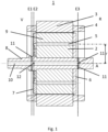
- FIG. 1 and 2 1 shows a longitudinal section of an electrical machine 1.
- the electrical machine consists of two main components: a rotor 2 and a stator 3.
- the stator 3 has winding heads 4 on both sides.
- the rotor 2 is constructed from rotor lamination stacks 9 that are mounted on a shaft 8.
- the shaft 8 is guided from a housing (not shown) on the front side V of the electrical machine 1.
- Channels 5 that extend along the axis A are arranged within the rotor lamination stacks 9. The number of channels 5 is adapted to the cooling problem.
- the channels 5 extend, for example, along a radius r at a uniform radial distance from one another, which does not correspond to the invention, or are distributed according to the invention along the circumference of different radii r1, r2.
- the rotor lamination stack 9 is provided with a cover plate on both the front side V and the back side R, which covers the rotor lamination stack.
- the cover disc On the front side V, the cover disc is designed as a balancing disc 7 with a structure, on the back side R an unstructured cover disc 6 is provided.
- a cooling channel 10 which extends from the front side V to the rear side R.
- the shaft 8 has transverse bores 11 in a first plane E1 and transverse bores 12 in a second plane E2 axially spaced therefrom. On the rear side R of the electrical machine 1, transverse bores 11 are provided in a single plane E3.
- the oil flow is shown by arrows.
- the cooling of the winding heads 4 takes place via the transverse bores 11, both on the front side V of the electrical machine and on the rear side R.
- the cooling oil is thrown out of the openings 11 and hits the winding heads 4 via the path 13. Since the transport of the oil depends on the rotational speed of the shaft 8 and on the amount of oil available, the cooling of the winding head 4 on the rear side R of the electrical machine is sometimes weaker because no more oil reaches it.
- the newly introduced cooling oil path 14 also ensures that the winding heads 4 on the rear side R of the electrical machine 1 are sufficiently cooled.
- the cooling oil path 14 initially extends radially from the transverse bore 12 of the shaft 8, meets the structure of the balancing disc 7, which is described in more detail below, is deflected and guided along the channels 5 of the rotor laminations 9. This part of the cooling oil exits at the rear R of the electrical machine 1 and is thrown towards the winding head 4 at the rear of the electrical machine.
- the permanent magnets not shown in the drawing are embedded in the rotor laminations 9 and are located close to the channels 5.
- the heat of the permanent magnets is dissipated by the cooling oil in the channels 5.
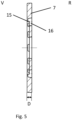
- the Figures 3 and 4 show a view of the front V of the electrical machine 1. A section through the Figure 3 The balancing disc 7 shown can be seen in Figure 5.
- the balancing disc 7 has a shoulder 15 in which the thickness D of the balancing disc is almost halved. This creates an edge approximately half the thickness of the balancing disc.
- the depth of the shoulder 15 is adapted to the specific design of the balancing disc and the cooling channels 5.
- the balancing disc 7 also has axial recesses in the form of pockets 16 through which the oil impacting on the shoulder 15 is guided axially to the rotor 2 and then through the channels 5.
- part of the oil quantity is collected by the balancing disc 7 and directed axially through the rotor 2.
- the remaining oil sprays through transverse openings 11 onto the winding heads and cools the stator.
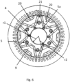
- Figure 6 shows the inventive solution, which is not limited to one type of channel.
- the figure shows winding heads 4 arranged around the rotor cores 9.
- Permanent magnets 20 are installed in a typical arrangement within the rotor cores 9.
- One set of permanent magnets 20 is located along the outer circumference of the rotor cores 9, while additional permanent magnets are arranged in a V, alternating inward and outward. This creates installation spaces 21 and 22 in the interstices between two permanent magnets 20.
- Channels 5 are distributed along a circumference of the first radius r1 in the installation space 21. Additionally, channels 5a are provided along a circumference with radius r2, which in this example have a smaller inner diameter than channels 5.
- a further advantageous arrangement uses channels arranged in the installation space 22 adjacent to three permanent magnets 20.
- the balancing disc is adapted accordingly according to the invention by means of further shoulders 15 and pockets 16 along the circumferences of the radii r1 and r2 etc.
Landscapes
- Engineering & Computer Science (AREA)
- Power Engineering (AREA)
- Motor Or Generator Cooling System (AREA)
Description
- Die Erfindung betrifft eine elektrische Maschine mit Stator und Rotor, wobei der Rotor Rotorblechpakete auf einer Welle montiert aufweist, wobei die Welle einen Ölkanal umfasst, und die Rotorblechpakete Kanäle parallel zur Achse der Welle und Abschlussscheiben endseitig aufweisen, wobei der Ölkanal Queröffnungen aufweist.
- Bei elektrischen Maschinen werden Permanentmagnete mit Seltenen Erden eingesetzt. Wird der Permanentmagnet zu heiß, besteht die Gefahr der Entmagnetisierung, wodurch die elektrische Maschine irreparabel Schaden nehmen kann. Daher ist bei Hybridfahrzeugen die Kühlung der elektrischen Maschine ein wesentlicher Faktor, unabhängig von der speziellen Einbauart.
- Besonders problematisch ist das Wärmemanagement in den 2,5- Hybrid-Architekturen. Ein Beispiel eines solches Getriebes findet sich in der
DE 10 2010 004 711 C5 . Durch die spezielle Anbindung kommt es beim Fahren mit hoher Fahrzeuggeschwindigkeit zu höheren Drehzahlen an der elektrischen Maschine, die durchaus über Minuten andauern können. - Durch die in der elektrischen Maschine auftretenden hohen Verluste kommt man dadurch in den Bereich, in dem die Temperaturen für die Magnete bereits kritisch werden.
- Deshalb muss aktiv Wärme aus den Rotorblechen und den magnetnahen Bereichen entnommen werden, um das elektrische System länger ohne Limitierung betreiben zu können.
- Die
JP 2011 254 580 A - Aus der
JP 2009- 118 686 A - Der in der zweiten Ebene angeordnete Kühlpfad verläuft über den Ölkanal in der Rotorwelle und einen Verteilerport und über eine Schalteinheit, die von einer Feder vorgespannt ist. Hält die Feder den Verteilerport geöffnet, kann Kühlmittel in die Kanäle des Rotorblechpakets fließen. Allerdings erfolgt der Ölfluss der beiden Kühlwege nicht parallel und immer gleichzeitig. Vielmehr erfolgt eine Steuerung der beiden Kühlpfade, so dass entweder der eine oder der andere Kühlölpfad aktiv ist.
-
WO 2019/ 049 397 A1 zeigt eine Kühlung mit einem Kühlkanal, der eine einzige Zufuhr über eine Verbindungsöffnung aufweist. Das Kühlmittel wird nicht über eine Rotorwelle abgeschleudert, sondern mit einer Pumpe speziell für die Rotorkanäle zur Verfügung gestellt. Es spritzt kein Öl durch Fliehkraft aus einer Bohrung auf einen Absatz. - Aus der
JP 2019- 30 051 A - Auch in der
JP 2018- 191 363 A -
JP 2009 118 686 A -
WO 2020 / 217 075 A1 zeigt eine Wuchtscheibe, welche einen Kühlölpfad auf der Vorderseite aufweist, wobei die Wuchtscheibe in die Kanäle des Rotorblechpakets geführt ist und die Wuchtscheibe mindestens einen umlaufenden Absatz aufweist, in dem entlang des Umfangs des Absatzes Durchbrüche oder Taschen zu den Kanälen im Rotorblechpaket vorgesehen sind, die das an dem Absatz aufprallende Öl axial zum Rotor geleitet wird. - Es ist Aufgabe der Erfindung, eine elektrische Maschine mit einem verbesserten Kühlsystem zu schaffen, die eine effiziente Kühlung des Rotors ermöglicht, bei gleichzeitiger Aufrechterhaltung der Stator-Kühlung.
- Die Aufgabe wird gelöst mit einer elektrischen Maschine mit Stator und Rotor, wobei der Rotor Rotorblechpakete auf einer Welle montiert aufweist, wobei die Welle einen Ölkanal umfasst, und die Rotorblechpakete Kanäle parallel zur Achse der Welle und Abschlussscheiben endseitig aufweisen, wobei der Ölkanal Queröffnungen aufweist, die an der Vorderseite der elektrischen Maschine in axial zueinander beabstandeten Ebenen angeordnet sind.
- Durch die Anordnung der Queröffnungen entstehen axial versetzte Ölstrahlen, die von der Welle weggeschleudert werden.
- Um sowohl den Stator als auch den Rotor zu kühlen, ist eine erste Ebene innerhalb der Dicke einer als Wuchtscheibe ausgelegte Abschlussscheibe des Rotorblechpakets auf der Vorderseite der elektrischen Maschine und eine zweite Ebene außerhalb der Wuchtscheibe im Bereich von Wickelköpfen des Stators vorgesehen.
- Die axial versetzt weggeschleuderten Ölstrahlen gehen einerseits an der Wuchtscheibe vorbei und andererseits direkt in eine interne Struktur der Wuchtscheibe hinein.
- Dadurch ergibt sich ein erster Kühlölpfad, der sich entlang des Ölkanals, durch die Querbohrungen der Vorderseite und der Rückseite der elektrischen Maschine erstreckt und das austretende Kühlöl auf Wickelköpfe geschleudert wird.
- Der zweiter Kühlölpfad ist über den Ölkanal, die Querbohrungen auf der Vorderseite, die Wuchtscheibe in die Kanäle des Rotorblechpakets geführt.
- Die Wuchtscheibe ist so ausgestaltet, dass die Wuchtscheibe mindestens einen umlaufenden Absatz aufweist, in dem entlang des Umfangs des Absatzes Durchbrüche oder Taschen zu den Kanälen im Rotorblechpaket vorgesehen sind.
- Der Absatz weist eine Tiefe im Bereich bis zur halben Dicke der Wuchtscheibe auf.
- Erfindungsgemäß liegen mehrere Absätze radial beabstandet voneinander mit gestaffelten Tiefen vor.
- Eine Wuchtscheibe mit mehreren Absätzen ist geeignet, erfindungsgemäß Kanäle mit unterschiedlichen radialen Abständen entsprechend der Absätze durch das Rotorblechpaket zu führen und so optimal Wärme in der Nähe der Permanentmagneten abzuführen.
-
-
Figur 1 zeigt eine elektrische Maschine im Schnitt, -
Figur 2 zeigt dasselbe Schnittbild mit skizzierter Ölführung, -
Figur 3 und 4 zeigen eine Aufsicht auf die Vorderseite der elektrischen Maschine, -
Figur 5 zeigt einen Längsschnitt durch eine Rotorwuchtscheibe, -
Figur 6 zeigt eine Aufsicht auf das Rotorblechpaket innerhalb des Stators. - Die
Figuren 1-5 entsprechen nicht der Erfindung, da sie lediglich einen Absatz (15) zeigen, an dem Kanäle (5) angeordnet sind. DieFigur 6 hingegen entspricht der Erfindung, da sie mehrere Absätze (15) mit daran angeordneten Kanälen (5,5a) mit unterschiedlich radialen Abständen (r1,r2) zeigt. - In den
Figuren 1 und2 ist in einem Längsschnitt eine elektrische Maschine 1 dargestellt. Die elektrische Maschine besteht aus den beiden Hauptkomponenten, einem Rotor 2 sowie einem Stator 3. Der Stator 3 weist beidseitig Wickelköpfe 4 auf. Der Rotor 2 ist aus Rotorblechpaketen 9 aufgebaut, die auf einer Welle 8 montiert sind. Die Welle 8 wird auf der Vorderseite V der elektrischen Maschine 1 aus einem, nicht dargestellten, Gehäuse geführt. Innerhalb der Rotorblechpakete 9 sind Kanäle 5 angeordnet, die sich entlang der Achse A erstrecken. Die Anzahl der Kanäle 5 ist dabei dem Kühlproblem anzupassen. - Die Kanäle 5 erstrecken sich beispielsweise entlang eines Radius r im gleichmäßigen radialen Abstand voneinander, welches nicht der Erfindung entspricht, oder sind erfindungsgemäß entlang des Umfangs unterschiedlicher Radien r1,r2 verteilt.
- Das Rotorblechpaket 9 ist sowohl auf der Vorderseite V als auch auf der Rückseite R mit einer Abschlussscheibe versehen, die das Rotorblechpaket abdeckt.
- Auf der Vorderseite V ist die Abschlussscheibe als Wuchtscheibe 7 mit einer Struktur ausgebildet, auf der Rückseite R ist eine unstrukturierte Abschlussscheibe 6 vorgesehen.
- In der Welle 8 des Rotors 2 ist ein Kühlkanal 10 vorhanden, der sich von der Vorderseite V bis zur Rückseite R erstreckt.
- Die Welle 8 weist in einer ersten Ebene E1 Querbohrungen 11 auf, sowie in einer zweiten, axial davon beanstandende Ebene E2 Querbohrungen 12. Auf der Rückseite R der elektrischen Maschine 1 sind Querbohrungen 11 in einer einzigen Ebenen E3 vorgesehen.
- In der Ebene E1 spritzt das Öl durch die Zentrifugalkraft aus dem Kanal 10 über die Querbohrungen 11 und einem freien Raum auf die Wickelköpfe 4. In der Ebene E2 spritzt Öl aus dem Kanal 10 und den Querbohrungen 12 an die, an der Wuchtscheibe 7 ausgebildete Struktur und wird über die Struktur in die Kanäle 5 der Rotorbleche 9 geführt.
- In der
Figur 2 ist der Ölfluss über Pfeile dargestellt. Die Kühlung der Wickelköpfe 4 erfolgt über die Querbohrungen 11, sowohl auf der Vorderseite V der elektrischen Maschine als auch auf der Rückseite R. Das Kühlöl wird aus den Öffnungen 11 geschleudert und trifft über den Pfad 13 auf die Wickelköpfe 4. Da der Transport des Öls von der Drehgeschwindigkeit der Welle 8 abhängig ist, sowie von der zur Verfügung gestellten Ölmenge, ist die Kühlung des Wickelkopfs 4 auf der Rückseite R der elektrischen Maschine manchmal schwächer ausgebildet, weil kein Öl mehr ankommt. - Durch den neu eingeführten Kühlölpfad 14 werden aber auch die Wickelköpfe 4 auf der Rückseite R der elektrischen Maschine 1 ausreichend gekühlt. Der Kühlölpfad 14 erstreckt sich zunächst radial von den Querbohrung 12 der Welle 8 ausgehend, trifft auf die im Folgenden näher ausgeführte Struktur der Wuchtscheibe 7, wird umgelenkt und entlang des Kanäle 5 der Rotorbleche 9 geführt. Auf der Rückseite R der elektrischen Maschine 1 tritt dieser Teil des Kühlöls aus und wird in Richtung auf den Wickelkopf 4 an der Rückseite der elektrischen Maschine geschleudert.
- Die in der Zeichnung nicht dargestellten Permanentmagneten sind in den Rotorblechen 9 eingebettet und befinden sich räumlich nahe an den Kanälen 5. Durch das Kühlöl in den Kanälen 5 wird die Wärme der Permanentmagnete abgeführt. Die
Figuren 3 und 4 zeigen eine Ansicht auf die Vorderseite V der elektrischen Maschine 1. Ein Schnitt durch die inFigur 3 dargestellte Wuchtscheibe 7 ist in Figur 5 zu erkennen. - Die Wuchtscheibe 7 weist in dem Ausführungsbeispiel einen Absatz 15 auf, in dem sich die Dicke D der Wuchtscheibe nahezu halbiert. Dadurch wird eine Kante mit in etwa der halben Dicke der Wuchtscheibe gebildet. Die Tiefe des Absatzes 15 ist an die spezielle Ausführung der Wuchtscheibe und den Kühlkanälen 5 angepasst.
- Die Wuchtscheibe 7 weist zudem axiale Aussparung in Form von Taschen 16 auf, durch die das an dem Absatz 15 aufprallende Öl axial zum Rotor 2 und dann durch die Kanäle 5 geleitet wird.
- Zur optimierten Kühlung der elektrischen Maschine wird also ein Teil der Ölmenge von der Wuchtscheibe 7 aufgefangen und axial durch den Rotor 2 geleitet. Das restliche Öl spritzt über Queröffnungen 11 auf die Wickelköpfe und kühlt den Stator.
-
Figur 6 zeigt die erfindungsgemäße Lösung, die sich nicht auf einen Typ von Kanälen beschränkt. - Die Figur zeigt Wickelkopfe 4, die um die Rotorblechpakete 9 angeordnet sind. Innerhalb der Rotorblechpakete 9 sind Permanentmagnete 20 in einer typischen Anordnung eingebaut. Ein Satz Permanentmagnete 20 liegt entlang des Außenumfangs der Rotorblechpakete 9, weitere Permanentmagnete sind als V angeordnet, alternierend nach innen und nach außen zulaufend. Dadurch ergeben sich Bauräume 21 und 22 jeweils in den Zwickeln zwischen zwei Permanentmagneten 20. Kanäle 5 sind auf einem Umfang des ersten Radius r1 im Bauraum 21 verteilt eingebracht. Zusätzlich sind Kanäle 5a entlang eines Umfangs mit Radius r2 vorhanden, die in diesem Beispiel einen geringeren Innendurchmesser aufweisen als die Kanäle 5.
- Eine weitere vorteilhafte Anordnung verwendet Kanäle, die im Bauraum 22 benachbart zu drei Permanentmagneten 20 angeordnet sind.
- Damit alle Kanäle 5, 5a mit Öl versorgt werden können ist die Wuchtscheibe erfindungsgemäß entsprechend angepasst durch weitere Absätze 15 und Taschen 16 entlang der Umfänge der Radien r1 und r2 usw.
Claims (3)
- Elektrische Maschine (1) mit Stator (3) und Rotor (2), wobei der Rotor (2) Rotorblechpakete (9) auf einer Welle (8) montiert aufweist, wobei die Welle (8) einen Ölkanal (10) umfasst, und wobei die Rotorblechpakete (9) Kanäle (5) parallel zur Achse (A) der Welle (8) und Abschlussscheiben (6, 7) endseitig der Rotorblechpakete (9) aufweisen, wobei der Ölkanal (10) Querbohrungen (11, 12) aufweist, die auf einer Vorderseite (V) der elektrische Maschine (1) in axial zueinander beabstandeten Ebenen (E1, E2) angeordnet sind und einen ersten und einen zweiten Kühlölpfad versorgen und eine erste Ebene (E2) der Ebenen (E1, E2) innerhalb der Dicke (D) einer als Wuchtscheibe (7) ausgelegte Abschlussscheibe verläuft und eine zweite Ebene (E1) außerhalb der Wuchtscheibe (7) im Bereich von Wickelköpfen (4) des Stators (3) verläuft, dadurch gekennzeichnet, dass der zweite Kühlölpfad über den Ölkanal (10), die Querbohrungen (12) , wobei Öl aus dem Kanal (10) und den Querbohrungen (12) spritzt, auf der Vorderseite (V), über die Wuchtscheibe (7) in die Kanäle (5) des Rotorblechpakets (9) geführt ist und die Wuchtscheibe (7) mindestens einen umlaufenden Absatz (15) aufweist, in dem entlang des Umfangs des Absatzes Durchbrüche oder Taschen (16) zu den Kanälen (5) im Rotorblechpaket vorgesehen sind, die das an dem Absatz (15) aufprallende Öl axial zum Rotor (2) leiten, wobei mehrere Absätze (15) radial beabstandet voneinander mit gestaffelter Tiefe vorliegen und Kanäle (5,5a) mit unterschiedlichen radialen Abständen (r1, r2) entsprechend der Absätze (15) durch das Rotorblechpaket (9) führen.
- Elektrische Maschine (1) nach Anspruch 1, dadurch gekennzeichnet, dass sich ein erster Kühlölpfad entlang des Ölkanals (10), durch die Querbohrungen (11) der Vorderseite (V) und einer der Rückseite (R) der elektrischen Maschine erstreckt und das austretende Kühlöl auf die Wickelköpfe (4) geschleudert wird.
- Elektrische Maschine (1) nach Anspruch 1, dadurch gekennzeichnet, dass der Absatz (15) eine Tiefe bis zu der halben Dicke (D) der Wuchtscheibe (7) aufweist.
Applications Claiming Priority (1)
| Application Number | Priority Date | Filing Date | Title |
|---|---|---|---|
| DE102021204671.1A DE102021204671A1 (de) | 2021-05-07 | 2021-05-07 | Elektrische Maschine mit Rotorkühlung |
Publications (2)
| Publication Number | Publication Date |
|---|---|
| EP4087095A1 EP4087095A1 (de) | 2022-11-09 |
| EP4087095B1 true EP4087095B1 (de) | 2025-06-04 |
Family
ID=81392706
Family Applications (1)
| Application Number | Title | Priority Date | Filing Date |
|---|---|---|---|
| EP22170521.3A Active EP4087095B1 (de) | 2021-05-07 | 2022-04-28 | Elektrische maschine mit rotorkühlung |
Country Status (4)
| Country | Link |
|---|---|
| US (1) | US12328053B2 (de) |
| EP (1) | EP4087095B1 (de) |
| CN (1) | CN115313720B (de) |
| DE (1) | DE102021204671A1 (de) |
Families Citing this family (9)
| Publication number | Priority date | Publication date | Assignee | Title |
|---|---|---|---|---|
| US12312091B2 (en) | 2022-10-06 | 2025-05-27 | Archer Aviation Inc. | Systems and methods for improved gearboxes for evtol aircraft |
| US11787551B1 (en) | 2022-10-06 | 2023-10-17 | Archer Aviation, Inc. | Vertical takeoff and landing aircraft electric engine configuration |
| US12227300B2 (en) | 2022-10-06 | 2025-02-18 | Archer Aviation Inc. | Systems and methods for oil maintenance in gearboxes for eVTOL aircraft |
| DE102022211820A1 (de) * | 2022-11-09 | 2024-05-16 | Robert Bosch Gesellschaft mit beschränkter Haftung | Rotor einer elektrischen Maschine |
| CN115664117B (zh) * | 2022-12-26 | 2023-03-03 | 河北乾顺节能科技有限公司 | 一种双定子永磁直驱电机液冷装置 |
| EP4425758A1 (de) * | 2023-03-02 | 2024-09-04 | Volvo Truck Corporation | Elektrische maschinenanordnung |
| DE102023205918A1 (de) * | 2023-06-23 | 2024-12-24 | Volkswagen Aktiengesellschaft | Rotor für eine elektrische Maschine und elektrische Maschine |
| CN117154982A (zh) * | 2023-08-11 | 2023-12-01 | 联合汽车电子有限公司 | 一种电机转子油冷冷却系统 |
| CN118293204A (zh) * | 2024-05-11 | 2024-07-05 | 浙江吉利控股集团有限公司 | 混动变速器及车辆 |
Family Cites Families (18)
| Publication number | Priority date | Publication date | Assignee | Title |
|---|---|---|---|---|
| JP4469670B2 (ja) * | 2004-07-08 | 2010-05-26 | 東芝産業機器製造株式会社 | 回転電機 |
| JP2009118686A (ja) | 2007-11-08 | 2009-05-28 | Aisin Aw Co Ltd | 回転電機の冷却構造 |
| DE102008033959B4 (de) * | 2008-07-21 | 2010-07-15 | Siemens Aktiengesellschaft | Elektrische Maschine mit Radialtrennblechen zur Kühlluftführung |
| DE102010004711C5 (de) | 2010-01-11 | 2018-11-15 | GETRAG B.V. & Co. KG | Verfahren zum Ansteuern eines Hybrid-Antriebsstrangs |
| JP5483095B2 (ja) | 2010-05-31 | 2014-05-07 | アイシン精機株式会社 | 回転電機の冷却構造 |
| JP6367875B2 (ja) * | 2016-08-25 | 2018-08-01 | 本田技研工業株式会社 | 回転電機のロータ構造 |
| US10931158B2 (en) * | 2016-09-29 | 2021-02-23 | Mitsubishi Electric Corporation | Rotor, rotary electric machine, and compressor |
| JP2018191363A (ja) | 2017-04-28 | 2018-11-29 | アイシン精機株式会社 | 回転電機冷却装置 |
| JP6954779B2 (ja) | 2017-07-26 | 2021-10-27 | 株式会社デンソー | 永久磁石式回転電機 |
| WO2019049397A1 (ja) | 2017-09-07 | 2019-03-14 | 三菱自動車工業株式会社 | 回転電機のロータ冷却構造 |
| DE102018111993A1 (de) * | 2018-05-18 | 2019-11-21 | Dr. Ing. H.C. F. Porsche Aktiengesellschaft | Rotor mit einer Endscheibenanordnung |
| JP7135522B2 (ja) * | 2018-07-13 | 2022-09-13 | トヨタ自動車株式会社 | 回転電機 |
| KR102113230B1 (ko) * | 2019-01-25 | 2020-05-20 | 엘지전자 주식회사 | 전동기 |
| JP7103267B2 (ja) | 2019-02-22 | 2022-07-20 | トヨタ自動車株式会社 | 冷却器 |
| WO2020217075A1 (ja) * | 2019-04-23 | 2020-10-29 | 日産自動車株式会社 | 回転電機 |
| DE102019124209B4 (de) * | 2019-09-10 | 2021-12-09 | Audi Ag | Kühlsystem für einen Elektromotor |
| JP2021050619A (ja) * | 2019-09-20 | 2021-04-01 | 株式会社富士通ゼネラル | 圧縮機 |
| WO2022077349A1 (zh) * | 2020-10-15 | 2022-04-21 | 舍弗勒技术股份两合公司 | 具有冷却流道的电机 |
-
2021
- 2021-05-07 DE DE102021204671.1A patent/DE102021204671A1/de active Pending
-
2022
- 2022-04-28 EP EP22170521.3A patent/EP4087095B1/de active Active
- 2022-05-02 US US17/734,241 patent/US12328053B2/en active Active
- 2022-05-07 CN CN202210492484.0A patent/CN115313720B/zh active Active
Also Published As
| Publication number | Publication date |
|---|---|
| US20220360133A1 (en) | 2022-11-10 |
| CN115313720A (zh) | 2022-11-08 |
| EP4087095A1 (de) | 2022-11-09 |
| US12328053B2 (en) | 2025-06-10 |
| CN115313720B (zh) | 2025-07-08 |
| DE102021204671A1 (de) | 2022-11-10 |
Similar Documents
| Publication | Publication Date | Title |
|---|---|---|
| EP4087095A1 (de) | Elektrische maschine mit rotorkühlung | |
| DE102016211872B4 (de) | Rotor von rotierender elektrischer Maschine | |
| EP3403319B1 (de) | Elektrische maschine | |
| DE102016210211B4 (de) | Rotor von rotierender elektrischer maschine | |
| EP3507889B1 (de) | Rotor für eine elektrische maschine | |
| WO2017162389A1 (de) | Elektrische maschine mit einer kühleinrichtung | |
| DE102014213159A1 (de) | Anordnung zur Statorkühlung eines elektrischen Motors | |
| DE112008001905T5 (de) | Rotierende elektrische Maschine | |
| DE102014018223A1 (de) | Elektrische Maschine, insbesondere Asynchronmaschine | |
| DE112011103347T5 (de) | Internes Kühlen einer Statorbaugruppe in einer elektrischen Maschine | |
| DE102015223462A1 (de) | Rotor, flüssigkeitsgekühlte, elektrische Maschine sowie Fahrzeug | |
| DE102013020331A1 (de) | Elektrische Maschine, insbesondere Asynchronmaschine | |
| WO2019072489A1 (de) | Rotorhohlwelle mit integriertem pumpenelement | |
| DE102021111700A1 (de) | Wickelkopfkühlung | |
| DE102023109925A1 (de) | Wärmeverwaltungsbaugruppe und -verfahren für elektrische maschine | |
| DE102019212256A1 (de) | Rotor mit minierten Streustegen | |
| DE102020129142B4 (de) | Läufer für eine rotierende elektrische Maschine | |
| DE102021131448A1 (de) | Kühlvorrichtung für einen Stator mit Kühlmantel außerhalb eines Innengehäuseteils | |
| DE102022213027A1 (de) | Rotor und elektrische Maschine | |
| DE112020000996T5 (de) | Elektrische Maschine Mit Internen Kühldurchgängen | |
| DE102023117610B3 (de) | Rotor eines Elektromotors mit Statorkühlung | |
| DE102023204449A1 (de) | Rotoranordnung zur verbesserten Kühlung eines Rotors | |
| DE102022207210A1 (de) | Gekühlte Rotoranordnung mit vergrößerter Rotorwellenaufnahme | |
| DE102018213558A1 (de) | Elektromaschine für ein Kraftfahrzeug und Stator für eine Elektromaschine | |
| DE102012200965A1 (de) | Vereinfachte Kühlung eines Läufers einer elektrischen Maschine |
Legal Events
| Date | Code | Title | Description |
|---|---|---|---|
| PUAI | Public reference made under article 153(3) epc to a published international application that has entered the european phase |
Free format text: ORIGINAL CODE: 0009012 |
|
| STAA | Information on the status of an ep patent application or granted ep patent |
Free format text: STATUS: THE APPLICATION HAS BEEN PUBLISHED |
|
| STAA | Information on the status of an ep patent application or granted ep patent |
Free format text: STATUS: REQUEST FOR EXAMINATION WAS MADE |
|
| AK | Designated contracting states |
Kind code of ref document: A1 Designated state(s): AL AT BE BG CH CY CZ DE DK EE ES FI FR GB GR HR HU IE IS IT LI LT LU LV MC MK MT NL NO PL PT RO RS SE SI SK SM TR |
|
| 17P | Request for examination filed |
Effective date: 20221025 |
|
| RBV | Designated contracting states (corrected) |
Designated state(s): AL AT BE BG CH CY CZ DE DK EE ES FI FR GB GR HR HU IE IS IT LI LT LU LV MC MK MT NL NO PL PT RO RS SE SI SK SM TR |
|
| GRAP | Despatch of communication of intention to grant a patent |
Free format text: ORIGINAL CODE: EPIDOSNIGR1 |
|
| STAA | Information on the status of an ep patent application or granted ep patent |
Free format text: STATUS: GRANT OF PATENT IS INTENDED |
|
| RIC1 | Information provided on ipc code assigned before grant |
Ipc: H02K 9/19 20060101ALI20241231BHEP Ipc: H02K 3/24 20060101ALI20241231BHEP Ipc: H02K 7/04 20060101ALI20241231BHEP Ipc: H02K 1/32 20060101AFI20241231BHEP |
|
| INTG | Intention to grant announced |
Effective date: 20250124 |
|
| GRAS | Grant fee paid |
Free format text: ORIGINAL CODE: EPIDOSNIGR3 |
|
| GRAA | (expected) grant |
Free format text: ORIGINAL CODE: 0009210 |
|
| STAA | Information on the status of an ep patent application or granted ep patent |
Free format text: STATUS: THE PATENT HAS BEEN GRANTED |
|
| AK | Designated contracting states |
Kind code of ref document: B1 Designated state(s): AL AT BE BG CH CY CZ DE DK EE ES FI FR GB GR HR HU IE IS IT LI LT LU LV MC MK MT NL NO PL PT RO RS SE SI SK SM TR |
|
| REG | Reference to a national code |
Ref country code: GB Ref legal event code: FG4D Free format text: NOT ENGLISH |
|
| REG | Reference to a national code |
Ref country code: CH Ref legal event code: EP |
|
| REG | Reference to a national code |
Ref country code: DE Ref legal event code: R096 Ref document number: 502022004124 Country of ref document: DE |
|
| REG | Reference to a national code |
Ref country code: IE Ref legal event code: FG4D Free format text: LANGUAGE OF EP DOCUMENT: GERMAN |
|
| REG | Reference to a national code |
Ref country code: DE Ref legal event code: R081 Ref document number: 502022004124 Country of ref document: DE Owner name: MAGNA PT B.V. & CO. KGAA, DE Free format text: FORMER OWNER: MAGNA PT B.V. & CO. KG, 74199 UNTERGRUPPENBACH, DE |
|
| REG | Reference to a national code |
Ref country code: NL Ref legal event code: MP Effective date: 20250604 |
|
| PG25 | Lapsed in a contracting state [announced via postgrant information from national office to epo] |
Ref country code: ES Free format text: LAPSE BECAUSE OF FAILURE TO SUBMIT A TRANSLATION OF THE DESCRIPTION OR TO PAY THE FEE WITHIN THE PRESCRIBED TIME-LIMIT Effective date: 20250604 Ref country code: FI Free format text: LAPSE BECAUSE OF FAILURE TO SUBMIT A TRANSLATION OF THE DESCRIPTION OR TO PAY THE FEE WITHIN THE PRESCRIBED TIME-LIMIT Effective date: 20250604 |
|
| REG | Reference to a national code |
Ref country code: LT Ref legal event code: MG9D |
|
| PG25 | Lapsed in a contracting state [announced via postgrant information from national office to epo] |
Ref country code: GR Free format text: LAPSE BECAUSE OF FAILURE TO SUBMIT A TRANSLATION OF THE DESCRIPTION OR TO PAY THE FEE WITHIN THE PRESCRIBED TIME-LIMIT Effective date: 20250905 Ref country code: NO Free format text: LAPSE BECAUSE OF FAILURE TO SUBMIT A TRANSLATION OF THE DESCRIPTION OR TO PAY THE FEE WITHIN THE PRESCRIBED TIME-LIMIT Effective date: 20250904 |
|
| PG25 | Lapsed in a contracting state [announced via postgrant information from national office to epo] |
Ref country code: PL Free format text: LAPSE BECAUSE OF FAILURE TO SUBMIT A TRANSLATION OF THE DESCRIPTION OR TO PAY THE FEE WITHIN THE PRESCRIBED TIME-LIMIT Effective date: 20250604 |
|
| PG25 | Lapsed in a contracting state [announced via postgrant information from national office to epo] |
Ref country code: BG Free format text: LAPSE BECAUSE OF FAILURE TO SUBMIT A TRANSLATION OF THE DESCRIPTION OR TO PAY THE FEE WITHIN THE PRESCRIBED TIME-LIMIT Effective date: 20250604 |
|
| PG25 | Lapsed in a contracting state [announced via postgrant information from national office to epo] |
Ref country code: HR Free format text: LAPSE BECAUSE OF FAILURE TO SUBMIT A TRANSLATION OF THE DESCRIPTION OR TO PAY THE FEE WITHIN THE PRESCRIBED TIME-LIMIT Effective date: 20250604 |
|
| PG25 | Lapsed in a contracting state [announced via postgrant information from national office to epo] |
Ref country code: RS Free format text: LAPSE BECAUSE OF FAILURE TO SUBMIT A TRANSLATION OF THE DESCRIPTION OR TO PAY THE FEE WITHIN THE PRESCRIBED TIME-LIMIT Effective date: 20250904 |
|
| PG25 | Lapsed in a contracting state [announced via postgrant information from national office to epo] |
Ref country code: LV Free format text: LAPSE BECAUSE OF FAILURE TO SUBMIT A TRANSLATION OF THE DESCRIPTION OR TO PAY THE FEE WITHIN THE PRESCRIBED TIME-LIMIT Effective date: 20250604 |
|
| PG25 | Lapsed in a contracting state [announced via postgrant information from national office to epo] |
Ref country code: NL Free format text: LAPSE BECAUSE OF FAILURE TO SUBMIT A TRANSLATION OF THE DESCRIPTION OR TO PAY THE FEE WITHIN THE PRESCRIBED TIME-LIMIT Effective date: 20250604 |
|
| PG25 | Lapsed in a contracting state [announced via postgrant information from national office to epo] |
Ref country code: PT Free format text: LAPSE BECAUSE OF FAILURE TO SUBMIT A TRANSLATION OF THE DESCRIPTION OR TO PAY THE FEE WITHIN THE PRESCRIBED TIME-LIMIT Effective date: 20251006 |
|
| PG25 | Lapsed in a contracting state [announced via postgrant information from national office to epo] |
Ref country code: IS Free format text: LAPSE BECAUSE OF FAILURE TO SUBMIT A TRANSLATION OF THE DESCRIPTION OR TO PAY THE FEE WITHIN THE PRESCRIBED TIME-LIMIT Effective date: 20251004 |
|
| PG25 | Lapsed in a contracting state [announced via postgrant information from national office to epo] |
Ref country code: SM Free format text: LAPSE BECAUSE OF FAILURE TO SUBMIT A TRANSLATION OF THE DESCRIPTION OR TO PAY THE FEE WITHIN THE PRESCRIBED TIME-LIMIT Effective date: 20250604 |
|
| PG25 | Lapsed in a contracting state [announced via postgrant information from national office to epo] |
Ref country code: CZ Free format text: LAPSE BECAUSE OF FAILURE TO SUBMIT A TRANSLATION OF THE DESCRIPTION OR TO PAY THE FEE WITHIN THE PRESCRIBED TIME-LIMIT Effective date: 20250604 |
|
| PG25 | Lapsed in a contracting state [announced via postgrant information from national office to epo] |
Ref country code: EE Free format text: LAPSE BECAUSE OF FAILURE TO SUBMIT A TRANSLATION OF THE DESCRIPTION OR TO PAY THE FEE WITHIN THE PRESCRIBED TIME-LIMIT Effective date: 20250604 |
|
| PG25 | Lapsed in a contracting state [announced via postgrant information from national office to epo] |
Ref country code: SK Free format text: LAPSE BECAUSE OF FAILURE TO SUBMIT A TRANSLATION OF THE DESCRIPTION OR TO PAY THE FEE WITHIN THE PRESCRIBED TIME-LIMIT Effective date: 20250604 |
|
| PG25 | Lapsed in a contracting state [announced via postgrant information from national office to epo] |
Ref country code: IT Free format text: LAPSE BECAUSE OF FAILURE TO SUBMIT A TRANSLATION OF THE DESCRIPTION OR TO PAY THE FEE WITHIN THE PRESCRIBED TIME-LIMIT Effective date: 20250604 |
|
| REG | Reference to a national code |
Ref country code: DE Ref legal event code: R097 Ref document number: 502022004124 Country of ref document: DE |
|
| PLBE | No opposition filed within time limit |
Free format text: ORIGINAL CODE: 0009261 |
|
| STAA | Information on the status of an ep patent application or granted ep patent |
Free format text: STATUS: NO OPPOSITION FILED WITHIN TIME LIMIT |
|
| PG25 | Lapsed in a contracting state [announced via postgrant information from national office to epo] |
Ref country code: DK Free format text: LAPSE BECAUSE OF FAILURE TO SUBMIT A TRANSLATION OF THE DESCRIPTION OR TO PAY THE FEE WITHIN THE PRESCRIBED TIME-LIMIT Effective date: 20250604 |
|
| REG | Reference to a national code |
Ref country code: CH Ref legal event code: L10 Free format text: ST27 STATUS EVENT CODE: U-0-0-L10-L00 (AS PROVIDED BY THE NATIONAL OFFICE) Effective date: 20260416 |
|
| 26N | No opposition filed |
Effective date: 20260305 |