EP4086723B1 - Fahrerassistenzverfahren, steuergerät und fahrzeug mit dem steuergerät - Google Patents
Fahrerassistenzverfahren, steuergerät und fahrzeug mit dem steuergerät Download PDFInfo
- Publication number
- EP4086723B1 EP4086723B1 EP22173549.1A EP22173549A EP4086723B1 EP 4086723 B1 EP4086723 B1 EP 4086723B1 EP 22173549 A EP22173549 A EP 22173549A EP 4086723 B1 EP4086723 B1 EP 4086723B1
- Authority
- EP
- European Patent Office
- Prior art keywords
- vehicle
- driver assistance
- assistance method
- corridor
- driving
- Prior art date
- Legal status (The legal status is an assumption and is not a legal conclusion. Google has not performed a legal analysis and makes no representation as to the accuracy of the status listed.)
- Active
Links
Images




Classifications
-
- B—PERFORMING OPERATIONS; TRANSPORTING
- B60—VEHICLES IN GENERAL
- B60W—CONJOINT CONTROL OF VEHICLE SUB-UNITS OF DIFFERENT TYPE OR DIFFERENT FUNCTION; CONTROL SYSTEMS SPECIALLY ADAPTED FOR HYBRID VEHICLES; ROAD VEHICLE DRIVE CONTROL SYSTEMS FOR PURPOSES NOT RELATED TO THE CONTROL OF A PARTICULAR SUB-UNIT
- B60W30/00—Purposes of road vehicle drive control systems not related to the control of a particular sub-unit, e.g. of systems using conjoint control of vehicle sub-units
- B60W30/08—Active safety systems predicting or avoiding probable or impending collision or attempting to minimise its consequences
- B60W30/095—Predicting travel path or likelihood of collision
-
- B—PERFORMING OPERATIONS; TRANSPORTING
- B62—LAND VEHICLES FOR TRAVELLING OTHERWISE THAN ON RAILS
- B62D—MOTOR VEHICLES; TRAILERS
- B62D15/00—Steering not otherwise provided for
- B62D15/02—Steering position indicators ; Steering position determination; Steering aids
- B62D15/027—Parking aids, e.g. instruction means
- B62D15/0275—Parking aids, e.g. instruction means by overlaying a vehicle path based on present steering angle over an image without processing that image
-
- B—PERFORMING OPERATIONS; TRANSPORTING
- B60—VEHICLES IN GENERAL
- B60W—CONJOINT CONTROL OF VEHICLE SUB-UNITS OF DIFFERENT TYPE OR DIFFERENT FUNCTION; CONTROL SYSTEMS SPECIALLY ADAPTED FOR HYBRID VEHICLES; ROAD VEHICLE DRIVE CONTROL SYSTEMS FOR PURPOSES NOT RELATED TO THE CONTROL OF A PARTICULAR SUB-UNIT
- B60W10/00—Conjoint control of vehicle sub-units of different type or different function
- B60W10/04—Conjoint control of vehicle sub-units of different type or different function including control of propulsion units
-
- B—PERFORMING OPERATIONS; TRANSPORTING
- B60—VEHICLES IN GENERAL
- B60W—CONJOINT CONTROL OF VEHICLE SUB-UNITS OF DIFFERENT TYPE OR DIFFERENT FUNCTION; CONTROL SYSTEMS SPECIALLY ADAPTED FOR HYBRID VEHICLES; ROAD VEHICLE DRIVE CONTROL SYSTEMS FOR PURPOSES NOT RELATED TO THE CONTROL OF A PARTICULAR SUB-UNIT
- B60W10/00—Conjoint control of vehicle sub-units of different type or different function
- B60W10/20—Conjoint control of vehicle sub-units of different type or different function including control of steering systems
-
- B—PERFORMING OPERATIONS; TRANSPORTING
- B60—VEHICLES IN GENERAL
- B60W—CONJOINT CONTROL OF VEHICLE SUB-UNITS OF DIFFERENT TYPE OR DIFFERENT FUNCTION; CONTROL SYSTEMS SPECIALLY ADAPTED FOR HYBRID VEHICLES; ROAD VEHICLE DRIVE CONTROL SYSTEMS FOR PURPOSES NOT RELATED TO THE CONTROL OF A PARTICULAR SUB-UNIT
- B60W50/00—Details of control systems for road vehicle drive control not related to the control of a particular sub-unit, e.g. process diagnostic or vehicle driver interfaces
- B60W50/08—Interaction between the driver and the control system
- B60W50/14—Means for informing the driver, warning the driver or prompting a driver intervention
-
- B—PERFORMING OPERATIONS; TRANSPORTING
- B60—VEHICLES IN GENERAL
- B60W—CONJOINT CONTROL OF VEHICLE SUB-UNITS OF DIFFERENT TYPE OR DIFFERENT FUNCTION; CONTROL SYSTEMS SPECIALLY ADAPTED FOR HYBRID VEHICLES; ROAD VEHICLE DRIVE CONTROL SYSTEMS FOR PURPOSES NOT RELATED TO THE CONTROL OF A PARTICULAR SUB-UNIT
- B60W60/00—Drive control systems specially adapted for autonomous road vehicles
- B60W60/001—Planning or execution of driving tasks
-
- B—PERFORMING OPERATIONS; TRANSPORTING
- B62—LAND VEHICLES FOR TRAVELLING OTHERWISE THAN ON RAILS
- B62D—MOTOR VEHICLES; TRAILERS
- B62D15/00—Steering not otherwise provided for
- B62D15/02—Steering position indicators ; Steering position determination; Steering aids
- B62D15/027—Parking aids, e.g. instruction means
- B62D15/0285—Parking performed automatically
-
- G—PHYSICS
- G05—CONTROLLING; REGULATING
- G05D—SYSTEMS FOR CONTROLLING OR REGULATING NON-ELECTRIC VARIABLES
- G05D1/00—Control of position, course, altitude or attitude of land, water, air or space vehicles, e.g. using automatic pilots
- G05D1/02—Control of position or course in two dimensions
- G05D1/021—Control of position or course in two dimensions specially adapted to land vehicles
- G05D1/0212—Control of position or course in two dimensions specially adapted to land vehicles with means for defining a desired trajectory
- G05D1/0221—Control of position or course in two dimensions specially adapted to land vehicles with means for defining a desired trajectory involving a learning process
-
- G—PHYSICS
- G05—CONTROLLING; REGULATING
- G05D—SYSTEMS FOR CONTROLLING OR REGULATING NON-ELECTRIC VARIABLES
- G05D1/00—Control of position, course, altitude or attitude of land, water, air or space vehicles, e.g. using automatic pilots
- G05D1/02—Control of position or course in two dimensions
- G05D1/021—Control of position or course in two dimensions specially adapted to land vehicles
- G05D1/0231—Control of position or course in two dimensions specially adapted to land vehicles using optical position detecting means
- G05D1/0246—Control of position or course in two dimensions specially adapted to land vehicles using optical position detecting means using a video camera in combination with image processing means
-
- G—PHYSICS
- G05—CONTROLLING; REGULATING
- G05D—SYSTEMS FOR CONTROLLING OR REGULATING NON-ELECTRIC VARIABLES
- G05D1/00—Control of position, course, altitude or attitude of land, water, air or space vehicles, e.g. using automatic pilots
- G05D1/02—Control of position or course in two dimensions
- G05D1/021—Control of position or course in two dimensions specially adapted to land vehicles
- G05D1/0268—Control of position or course in two dimensions specially adapted to land vehicles using internal positioning means
- G05D1/0274—Control of position or course in two dimensions specially adapted to land vehicles using internal positioning means using mapping information stored in a memory device
-
- B—PERFORMING OPERATIONS; TRANSPORTING
- B60—VEHICLES IN GENERAL
- B60R—VEHICLES, VEHICLE FITTINGS, OR VEHICLE PARTS, NOT OTHERWISE PROVIDED FOR
- B60R2300/00—Details of viewing arrangements using cameras and displays, specially adapted for use in a vehicle
- B60R2300/10—Details of viewing arrangements using cameras and displays, specially adapted for use in a vehicle characterised by the type of camera system used
-
- B—PERFORMING OPERATIONS; TRANSPORTING
- B60—VEHICLES IN GENERAL
- B60R—VEHICLES, VEHICLE FITTINGS, OR VEHICLE PARTS, NOT OTHERWISE PROVIDED FOR
- B60R2300/00—Details of viewing arrangements using cameras and displays, specially adapted for use in a vehicle
- B60R2300/20—Details of viewing arrangements using cameras and displays, specially adapted for use in a vehicle characterised by the type of display used
-
- B—PERFORMING OPERATIONS; TRANSPORTING
- B60—VEHICLES IN GENERAL
- B60R—VEHICLES, VEHICLE FITTINGS, OR VEHICLE PARTS, NOT OTHERWISE PROVIDED FOR
- B60R2300/00—Details of viewing arrangements using cameras and displays, specially adapted for use in a vehicle
- B60R2300/30—Details of viewing arrangements using cameras and displays, specially adapted for use in a vehicle characterised by the type of image processing
- B60R2300/304—Details of viewing arrangements using cameras and displays, specially adapted for use in a vehicle characterised by the type of image processing using merged images, e.g. merging camera image with stored images
-
- B—PERFORMING OPERATIONS; TRANSPORTING
- B60—VEHICLES IN GENERAL
- B60W—CONJOINT CONTROL OF VEHICLE SUB-UNITS OF DIFFERENT TYPE OR DIFFERENT FUNCTION; CONTROL SYSTEMS SPECIALLY ADAPTED FOR HYBRID VEHICLES; ROAD VEHICLE DRIVE CONTROL SYSTEMS FOR PURPOSES NOT RELATED TO THE CONTROL OF A PARTICULAR SUB-UNIT
- B60W50/00—Details of control systems for road vehicle drive control not related to the control of a particular sub-unit, e.g. process diagnostic or vehicle driver interfaces
- B60W50/08—Interaction between the driver and the control system
- B60W50/14—Means for informing the driver, warning the driver or prompting a driver intervention
- B60W2050/146—Display means
-
- B—PERFORMING OPERATIONS; TRANSPORTING
- B60—VEHICLES IN GENERAL
- B60W—CONJOINT CONTROL OF VEHICLE SUB-UNITS OF DIFFERENT TYPE OR DIFFERENT FUNCTION; CONTROL SYSTEMS SPECIALLY ADAPTED FOR HYBRID VEHICLES; ROAD VEHICLE DRIVE CONTROL SYSTEMS FOR PURPOSES NOT RELATED TO THE CONTROL OF A PARTICULAR SUB-UNIT
- B60W2420/00—Indexing codes relating to the type of sensors based on the principle of their operation
- B60W2420/40—Photo, light or radio wave sensitive means, e.g. infrared sensors
- B60W2420/403—Image sensing, e.g. optical camera
-
- B—PERFORMING OPERATIONS; TRANSPORTING
- B60—VEHICLES IN GENERAL
- B60W—CONJOINT CONTROL OF VEHICLE SUB-UNITS OF DIFFERENT TYPE OR DIFFERENT FUNCTION; CONTROL SYSTEMS SPECIALLY ADAPTED FOR HYBRID VEHICLES; ROAD VEHICLE DRIVE CONTROL SYSTEMS FOR PURPOSES NOT RELATED TO THE CONTROL OF A PARTICULAR SUB-UNIT
- B60W2554/00—Input parameters relating to objects
- B60W2554/80—Spatial relation or speed relative to objects
Definitions
- the present invention relates to a training method for a driver assistance method of a vehicle, the driver assistance method, a control device for carrying out the training method and for carrying out the driver assistance method, and a vehicle with the control device.
- the document US 2010/0049402 A1 discloses a driving assistance system for parking a vehicle, wherein a target parking position can be set by a user of the driving assistance system.
- the object of the present invention is to improve support for a driver through a driver assistance method at a known location.
- the present invention relates to a training method for a driver assistance method of a vehicle, wherein the vehicle has at least one Camera included.
- the training method captures a sequence of camera images, in particular a video sequence, during a user-guided training drive of the vehicle along a desired trajectory.
- the driver drives the vehicle along a desired trajectory from a starting point to an end point, with a video sequence being recorded by the camera during this training drive.
- the user drives the vehicle from an entrance to an underground car park to a parking space in the underground car park.
- the user drives the vehicle from a position in front of a property entrance to a parking space on the property.
- a driving corridor for the driver assistance method is then determined along the desired trajectory depending on image processing of the captured sequence of camera images.
- a tolerance range is determined for the trajectory desired by the user, wherein the tolerance range or the driving corridor represents an area in which the vehicle may be moved during a later implementation of the driver assistance method, for example to avoid non-stationary obstacles.
- the captured sequence of camera images and/or an environmental model determined depending on the captured sequence of camera images is shown to the user on a display.
- the determined driving corridor is displayed as an overlay superimposed on the display.
- an input from the user to adjust a limitation of the determined travel corridor is recorded.
- the user changes the boundary of the determined driving corridor during the display.
- the determined driving corridor is then adapted depending on the recorded input and the determined driving corridor and/or the adapted driving corridor is stored in an electronic memory of the vehicle.
- the advantage arises that a vehicle can be moved semi-automatically or automatically within the driving corridor on a variable trajectory while the driver assistance method is being carried out, that is, for example, it can avoid obstacles such as a ball without the driver assistance method being aborted must become.
- the adjustment of the driving corridor by the user also has the advantage that For example, driving on flower beds or a lawn or driving over curbs is prevented during the driver assistance procedure. Undesirable trajectories are thus avoided during implementation of the driver assistance method by the training method.
- location coordinates of the vehicle are recorded during the training process.
- the location coordinates can represent the position relative to a global reference point (e.g. GPS coordinates) or relative to a specific position or a reference point of the desired trajectory, e.g. a starting point of the trajectory.
- the stored travel corridor is then assigned to the recorded location coordinates.
- distances between the vehicle and objects in the area surrounding the vehicle are recorded during the training drive guided by the user, in particular an environmental model or a depth map being determined depending on the recorded distances.
- the travel corridor is then additionally determined depending on the recorded distances or the depth map or the environmental model. This advantageously defines the driving corridor more precisely relative to the surroundings.
- objects and/or obstacles in the environment, such as curbs are recognized more reliably.
- At least one segment, a segment boundary, an object edge and/or objects are detected depending on an image analysis or image processing of at least one captured camera image and/or depending on captured distance data.
- segment or object recognition is carried out using a neural network that is trained for the respective recognition target.
- the detected segment, the detected segment boundary, the detected object edge and/or the detected object are then additionally displayed on a display in the display of the captured sequence of camera images and/or the determined environmental model as an overlay superimposed on the display. This creates the advantage that the user is supported by the displayed segment, the displayed segment boundary, the displayed object edge and/or the displayed object when entering to adjust a boundary of the determined travel corridor.
- the boundary of the determined travel corridor is pre-adjusted depending on the detected segment, the detected segment boundary, the detected object edge and/or the detected object. This creates the advantage that the input for adjusting the limitation of the determined travel corridor is made easier for the user and/or the travel corridor is automatically corrected before the display or input.
- the adjustment of the limitation of the determined driving corridor can take place in sections along the determined driving corridor or along the desired trajectory depending on the user's input and/or depending on markings displayed in the representation at the boundaries of the displayed driving corridor.
- the user can advantageously change the boundary of the determined driving corridor by moving a finger on a touch screen.
- a time input for carrying out the driver assistance method is recorded by the user.
- the saved travel corridor is then assigned to the recorded time input. This creates the advantage that, for example, parking the vehicle in the morning can be done automatically at a specified time, which reduces the user's time and operating effort.
- the invention also relates to a driver assistance method for the vehicle.
- the driver assistance method includes detection of a start input.
- the start input to start the driver assistance method is preferably made by the user. Alternatively, the start input can be made automatically depending on the assigned location coordinates and/or depending on the assigned time input.
- a capture of a sequence of camera images and/or a capture of distances between the vehicle and objects in an area surrounding the vehicle is carried out.
- the saved driving corridor is then loaded, the saved driving corridor being determined by the training method according to the invention.
- a determination of at least one assisted trajectory within the driving corridor is then carried out depending on the vehicle geometry, depending on the recorded sequence of camera images and/or the recorded distances, and depending on the loaded driving corridor.
- the vehicle is then controlled depending on the determined assisted trajectory, so that the vehicle is only moved within the travel corridor, with at least one drive motor and/or a steering motor of the vehicle being controlled.
- the driver assistance method advantageously enables a semi-automatic or automatic journey of the vehicle from a starting point along a situation-dependent assisted trajectory to an end point or the avoidance of obstacles within the driving corridor, the driving corridor being precisely defined by the user.
- the location coordinates of the vehicle are recorded in the driver assistance method and the stored driving corridor is loaded depending on the recorded location coordinates.
- the driver assistance method provides a visual and/or acoustic display of a warning for the user, in particular on a mobile electronic device, and the driver assistance process has been aborted.
- the invention also relates to a control device, wherein the control device is set up to carry out a training method according to the invention and a driver assistance method according to the invention.
- the invention also relates to the vehicle with the control device according to the invention.
- a vehicle 100 is shown in supervision.
- the vehicle 100 has a drive motor 101 for driving the vehicle 100 and a steering motor 102 for steering the vehicle 100.
- a control unit 104 of the vehicle 100 is set up to control the drive motor 101 and the steering motor 102.
- a display 103 for displaying information for the user of the vehicle 100 is also arranged in the vehicle 100.
- the display 103 is controlled by a control device 104 and can include a touch screen for recording user input or alternative input means.
- the control device 104 is set up to capture camera data or captured camera images and/or a sequence of camera images or video sequences from a forward-facing camera 105, a backward-facing camera 106 and two laterally arranged wide-angle cameras 107 and use the display 103 to display these captured To control camera data and/or an environmental model.
- the cameras 105, 106 and 107 are set up to capture camera images or video sequences of the surroundings of the vehicle 100. Additional cameras can be arranged.
- the vehicle 100 has an ultrasonic sensor system.
- the ultrasonic sensor system includes ten ultrasonic sensors 108, which are connected to the control device 104.
- the control device 104 is therefore set up to record the distances between the vehicle 100 and objects in the surroundings of the vehicle 100, which are detected by means of the ultrasonic sensors 108. Furthermore, a mobile electronic device 121 with a display device 122 can be connected to the control unit 104 of the vehicle 100 via a wireless radio connection, wherein the display device 122 can have a touch screen for recording an input from the user 120 or alternative input means of the mobile electronic device 121 .
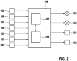
- FIG 2 is the control unit 104 of the exemplary embodiment of Figure 1 shown as a block diagram.
- the control device 104 captures camera data, ie camera images and/or a sequence of camera images or a video sequence, from the front-facing camera 105, the rear-facing camera 106 and the two side-mounted wide-angle cameras 107. Furthermore, the control device 104 captures distance data from the Ultrasonic sensors 108 of the ultrasonic sensor system. Furthermore is the control device 104 is set up to record an input from the user by means of a touch screen of the display 103 or the display device 122 and/or another input means 203, the input means 203 being arranged, for example, on the steering wheel of the vehicle 100.
- the connection to the touch screen 122 of the mobile electronic device 121 takes place via a wireless radio connection.
- the control device also has a computing unit 201, which is connected to an electronic memory 202 of the control device 104.
- the control unit 104 is set up to control the display 103, the display device 122, the drive motor 101 and/or the steering motor 102.
- a flowchart of a training method for a driver assistance method is shown as a block diagram.
- a step 310 while the user is carrying out the training method, that is, while the user is moving the vehicle 100 along a desired trajectory from a starting point to an end point, at least one sequence of camera images of the surroundings of the vehicle 100 is created using the at least one camera 105, 106 and/or 107 recorded.
- distances can be detected using the ultrasonic sensor system or the ultrasonic sensors 108.
- a detection 330 of location coordinates of the vehicle 100 can also take place.
- an image analysis 340 of at least one camera image of the captured sequence of camera images objects, object boundaries, segments and/or segment boundaries can optionally be recognized in the camera image.
- the recognition by the image analysis 340 is carried out, for example, by means of a neural network that has been trained using a large number of training data.
- the determined driving corridor corresponds to the driving path or driving area traveled during the training process along the desired trajectory of the vehicle 100, the driving corridor preferably comprising the driving path traveled and an additional tolerance range.
- the tolerance range extends the traveled travel tube laterally, for example, by 1 cm to 5 m.
- the travel corridor represents a movement during the driver assistance process of the vehicle 100 permitted or passable area. It can optionally be provided that in a step 360 the determined driving corridor is pre-adjusted depending on the detected segment, the detected segment boundary, the detected object edge and/or the detected object in the surroundings of the vehicle 100. Subsequently, in step 370, the captured sequence of camera images and/or an environmental model determined depending on the captured sequence of camera images is displayed on the display 103, 122. At least the determined or pre-adjusted driving corridor is superimposed on this display as an overlay. In a further step 380, an input from the user to adjust a limitation of the determined driving corridor is recorded during the display 370.
- the user can easily move the boundary of the driving corridor on a touch screen of the display 103 or 122 by moving a finger.
- the capture 380 of the user's input can take place in sections along the determined travel corridor or the desired trajectory and/or depending on markings displayed in the display at the boundaries of the displayed travel corridor.
- the user then independently defines the driving corridor to be saved.
- An adjustment 390 of the determined travel corridor then takes place depending on the input recorded in step 380.
- the determined or pre-adapted driving corridor or the driving corridor adapted by the driver is saved in a step 395.
- an assignment 396 of the stored driving corridor to the recorded location coordinates can take place.
- a time input for carrying out the driver assistance method is recorded 397 by the user and that this time input is assigned to the stored driving corridor in a step 398.
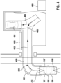
- FIG 4 an environment model with a superimposed display of the traveled or desired trajectory 400 is shown.
- the user drives this desired trajectory 400 during the training process by manually steering the vehicle 100 from a starting position 410 to an end position or parking position 405.
- the cameras 105, 106 and/or 107 record the surroundings of the vehicle 100.
- the environment model shown is dependent on the camera images captured by the cameras 105, 106 and/or 107 and/or depending on the distances captured by the ultrasonic sensors 108 determined.
- the trajectory For example, 400 consists, as in Figure 4 shown, from several travel sections 401, 402, 403, 404, 405 and 410, ie a first right turn 401, a straight exit 402, a second right turn 403 and a reset 404 in reverse gear as well as the start position 410 and the end position 405.
- a Driving hose 450 shown in dashed lines can be seen.
- the driving route 450 represents the area actually traveled by the vehicle 100 during the training trip.
- the area that can in principle be driven by the vehicle 100 is not evenly distributed around the driving tube 450; for example, the flower bed 460 and a children's playground 480 located directly next to the driving tube should not be driven over during a driving assistance procedure.
- Figure 5 is an environment model according to the Figure 4 with the determined driving corridor 500 displayed.
- the driving route 450 lies within the determined driving corridor 500. It can be seen that the determined driving corridor 500 extends the traveled driving route 450 by a tolerance range 510, shown hatched here, which can therefore also be traveled by the vehicle during the driver assistance procedure to be carried out later.
- FIG 6 is an environment model according to the Figures 4 and 5 shown with the pre-adjusted driving corridor 600 displayed.
- the determined driving corridor is expanded to asphalt ground based on a segment recognized by image processing.
- a children's playground segment was recognized using image processing, with a predetermined minimum distance range being provided for this area.
- the pre-adjusted driving corridor is therefore adapted depending on the determined driving corridor, the recognized “asphalted ground” and “children's playground” segments.
- recognized segments, recognized segment boundaries, recognized objects and/or recognized object boundaries can be highlighted as an overlay in the display of the displayed travel corridor, so that a user can be on a recognized segment while recording the input to adjust the boundary of the displayed travel corridor. can easily orientate recognized segment boundaries, a recognized object and/or recognized object boundaries.
- Figure 7 shows a representation of an environment model according to Figures 4 to 6 , whereby a driving corridor (700) adapted by the user is superimposed on the environmental model as an overlay. It can be seen that the user has changed the boundary of the pre-adjusted driving corridor at certain points, for example by moving the boundary of the pre-adapted driving corridor in Figure 6 by dragging your finger on a touch screen so that the adapted driving corridor no longer contains certain areas or contains them additionally.
- FIG. 8 a flowchart of the driver assistance process is shown as a block diagram.
- the driver assistance method begins with a detection 810 of a start input. This method step can be carried out by manual input by the user or automatically depending on recorded current location coordinates of the vehicle 100. Subsequently, in step 820, a sequence of camera images and/or distances between the vehicle 100 and objects in an environment of the vehicle 100 are recorded. This detection 820 is carried out continuously throughout the entire driver assistance process.
- the stored driving corridor 500, 600 or 700 is loaded from the electronic memory 202 of the control device 104 by the computing unit 201 of the control device 104. The loading 840 optionally takes place depending on location coordinates recorded in an optional step 830.
- the computing unit 201 determines at least one assisted trajectory depending on a vehicle geometry, depending on the captured sequence of camera images and/or the captured distances, and depending on the loaded driving corridor 500, 600 or 700.
- the vehicle geometry of the vehicle 100 is, for example also stored in memory 202.
- the assisted trajectory can deviate in any way from the trajectory followed during the training procedure. However, the assisted trajectory always lies within the loaded driving corridor 500, 600 or 700. This is followed by, for example, a time-delayed control 870 of the vehicle 100 depending on the determined assisted trajectory, with at least one drive motor 101 and / or a steering motor 102 of the vehicle 100, for example automatically be controlled.
- the driver assistance method allows the user of the driver assistance method to leave the vehicle 100, for example, at the starting position or shortly after the start input. It can des It can also be provided that the user is warned, for example on a mobile electronic device 121, and the driver assistance process is ended if no obstacle-free, assisted trajectory within the loaded driving corridor 700 can be determined in step 850.
- the detection 820 of the sequence of camera images and/or distances, the determination 840 of the assisted trajectory, the warning 860 as well as the termination 861 and the control 870 of the vehicle 100 are repeated until the target position 405 is reached, so that, for example, the determined assisted trajectory is ongoing can be updated or adjusted.
Landscapes
- Engineering & Computer Science (AREA)
- Mechanical Engineering (AREA)
- Transportation (AREA)
- Automation & Control Theory (AREA)
- Chemical & Material Sciences (AREA)
- Combustion & Propulsion (AREA)
- Radar, Positioning & Navigation (AREA)
- Physics & Mathematics (AREA)
- Aviation & Aerospace Engineering (AREA)
- Remote Sensing (AREA)
- General Physics & Mathematics (AREA)
- Human Computer Interaction (AREA)
- Multimedia (AREA)
- Computer Vision & Pattern Recognition (AREA)
- Electromagnetism (AREA)
- Traffic Control Systems (AREA)
- Control Of Driving Devices And Active Controlling Of Vehicle (AREA)
Description
- Die vorliegende Erfindung betrifft ein Trainingsverfahren für ein Fahrerassistenzverfahren eines Fahrzeugs, das Fahrerassistenzverfahren, ein Steuergerät zur Durchführung des Trainingsverfahrens und zur Durchführung des Fahrerassistenzverfahrens sowie ein Fahrzeug mit dem Steuergerät.
- Das Dokument
US 2010/0049402 A1 offenbart ein Fahrassistenzsystem zum Einparken eines Fahrzeugs, wobei eine Zielparkposition von einem Nutzer des Fahrassistenzsystems eingestellt werden kann. - Das Dokument
US 9,522,675 B1
Sowohl dieDE 10 2016 122215 A1 als auch dieDE 10 2010 023162 A1 zeigen die folgenden Merkmale:
Fahrerassistenzverfahren für ein Fahrzeug mit den folgenden Verfahrensschritten - Erfassung einer Starteingabe, und
- Erfassung einer Abfolge von Kamerabildern,
- Laden eines gespeicherten Fahrkorridors,
- Ermittlung einer assistierten Trajektorie in Abhängigkeit der erfassten Abfolge von Kamerabildern; und
- Ansteuerung des Fahrzeugs in Abhängigkeit der ermittelten assistierten Trajektorie, wobei ein Antriebsmotor und ein Lenkmotor des Fahrzeugs angesteuert werden.
- Die Aufgabe der vorliegenden Erfindung ist es, eine Unterstützung eines Fahrers durch ein Fahrerassistenzverfahren an einem bekannten Ort zu verbessern.
- Die obige Aufgabe wird gemäß der unabhängigen Ansprüche 1, 4 oder 5 gelöst. Die vorliegende Erfindung betrifft ein Trainingsverfahren für ein Fahrerassistenzverfahren eines Fahrzeugs, wobei das Fahrzeug zumindest eine Kamera umfasst. Zunächst erfolgt durch das Trainingsverfahren eine Erfassung einer Abfolge von Kamerabildern, insbesondere einer Videosequenz, während einer durch einen Nutzer geführten Trainingsfahrt des Fahrzeugs entlang einer gewünschten Trajektorie. Anders ausgedrückt fährt der Fahrer das Fahrzeug entlang einer von ihm gewünschten Trajektorie von einem Startpunkt zu einem Endpunkt, wobei während dieser Trainingsfahrt mittels der Kamera eine Videosequenz erfasst wird. Zum Beispiel fährt der Nutzer das Fahrzeug von einem Eingang einer Tiefgarage zu einem Parkplatz der Tiefgarage. In einem anderen Beispiel fährt der Nutzer das Fahrzeug von einer Position vor einer Einfahrt eines Grundstückes zu einem Parkplatz auf dem Grundstück. Anschließend wird entlang der gewünschten Trajektorie ein Fahrkorridor für das Fahrerassistenzverfahren in Abhängigkeit einer Bildverarbeitung der erfassten Abfolge von Kamerabildern ermittelt. Mit anderen Worten wird zu der durch den Nutzer gewünschten Trajektorie ein Toleranzbereich bestimmt, wobei der Toleranzbereich beziehungsweise der Fahrkorridor einen Bereich repräsentiert, in dem das Fahrzeug während einer späteren Durchführung des Fahrerassistenzverfahrens bewegt werden darf, beispielsweise zur Umfahrung von nicht-stationären Hindernissen. In einem nachfolgenden Schritt wird dem Nutzer die erfasste Abfolge von Kamerabildern und/oder eines in Abhängigkeit der erfassten Abfolge von Kamerabildern ermittelten Umgebungsmodells auf einem Display angezeigt. Bei dieser Darstellung wird der ermittelte Fahrkorridor als eine der Darstellung überlagerte Einblendung angezeigt. Während dieser Darstellung wird eine Eingabe des Nutzers zur Anpassung einer Begrenzung des ermittelten Fahrkorridors erfasst. Mit anderen Worten ändert der Nutzer die Begrenzung des ermittelten Fahrkorridors während der Darstellung. Danach erfolgt eine Anpassung des ermittelten Fahrkorridors in Abhängigkeit der erfassten Eingabe und eine Speicherung des ermittelten Fahrkorridors und/oder des angepassten Fahrkorridors in einem elektronischen Speicher des Fahrzeugs.
- Durch die Bestimmung des Fahrkorridors mittels des Trainingsverfahrens entsteht der Vorteil, dass ein Fahrzeug während der Durchführung des Fahrerassistenzverfahrens halbautomatisch oder automatisch innerhalb des Fahrkorridors auf einer variablen Trajektorie bewegt werden kann, d.h. beispielsweise Hindernissen, wie einem Ball, ausweichen kann ohne, dass das Fahrerassistenzverfahren abgebrochen werden muss. Die Anpassung des Fahrkorridors durch den Nutzer weist darüber hinaus den Vorteil auf, dass beispielsweise das Befahren von Blumenbeeten oder einem Rasen oder das Überfahren von Bordsteinkanten während des Fahrerassistenzverfahrens verhindert wird. Somit werden unerwünschte Trajektorien während einer Durchführung des Fahrerassistenzverfahrens durch das Trainingsverfahren vermieden.
- In einer bevorzugten Ausführung der Erfindung erfolgt während des Trainingsverfahrens eine Erfassung von Ortskoordinaten des Fahrzeugs. Die Ortskoordinaten können die Position relativ zu einem globalen Referenzpunkt (z.B. GPS-Koordinaten) oder relativ zu einer spezifischen Position beziehungsweise einem Referenzpunkt der gewünschten Trajektorie, z.B. einem Startpunkt der Trajektorie, darstellen. Anschließend erfolgt eine Zuordnung des gespeicherten Fahrkorridors zu den erfassten Ortskoordinaten. Durch diese Ausführung entsteht der Vorteil, dass das Fahrerassistenzverfahren an mehreren Orten mit einem ortsabhängig bestimmten Fahrkorridor durchgeführt werden kann und, dass das Fahrerassistenzverfahren halbautomatisch oder automatisch in Abhängigkeit einer Erfassung von Ortskoordinaten gestartet werden kann.
- In einer besonders bevorzugten Ausführungsform erfolgt eine Erfassung von Abständen zwischen dem Fahrzeug und Objekten in der Umgebung des Fahrzeugs während der durch den Nutzer geführten Trainingsfahrt, wobei insbesondere ein Umgebungsmodell beziehungsweise eine Tiefenkarte in Abhängigkeit der erfassten Abstände bestimmt wird. Anschließend wird der Fahrkorridor zusätzlich in Abhängigkeit der erfassten Abstände beziehungsweise der Tiefenkarte beziehungsweise des Umgebungsmodells ermittelt. Dadurch wird vorteilhafterweise der Fahrkorridor relativ zur Umgebung genauer definiert. Außerdem werden in dieser Ausführungsform Objekte und/oder Hindernisse in der Umgebung, beispielsweise Bordsteinkanten, zuverlässiger erkannt. Darüber hinaus ergibt sich der Vorteil, dass die Erfassung von Bilddaten sowie deren Auswertung lediglich während des Trainingsverfahrens durchgeführt werden muss, während eine Fahrttrajektorie für eine spätere Durchführung des Fahrerassistenzverfahrens alternativ oder zusätzlich auf erfassten Abständen basiert werden kann, beispielsweise um das Fahrassistenzverfahren zuverlässig bei ungünstigen Licht- oder Witterungsverhältnisse durchzuführen oder allgemein die Genauigkeit des Fahrkorridors zu verbessern.
- In einer Weiterführung erfolgt eine Erkennung von mindestens einem Segment, einer Segmentgrenze, einer Objektkante und/oder Objekten in Abhängigkeit einer Bildanalyse beziehungsweise Bildverarbeitung von zumindest einem erfassten Kamerabild und/oder in Abhängigkeit von erfassten Abstandsdaten. Beispielsweise erfolgt eine Segment- oder Objekterkennung mittels eines neuronalen Netzes, welches auf das jeweilige Erkennungsziel angelernt ist. Anschließend wird in der Darstellung der erfassten Abfolge von Kamerabildern und/oder des ermittelten Umgebungsmodells auf einem Display zusätzlich das erkannte Segment, die erkannte Segmentgrenze, die erkannte Objektkante und/oder das erkannte Objekt als eine der Darstellung überlagerte Einblendung angezeigt. Dadurch entsteht der Vorteil, dass der Nutzer bei der Eingabe zur Anpassung einer Begrenzung des ermittelten Fahrkorridors durch das angezeigte Segment, die angezeigte Segmentgrenze, die angezeigte Objektkante und/oder das angezeigte Objekt unterstützt wird. Optional oder alternativ erfolgt eine Voranpassung der Begrenzung des ermittelten Fahrkorridors in Abhängigkeit des erkannten Segments, der erkannten Segmentgrenze, der erkannten Objektkante und/oder des erkannten Objekts. Dadurch entsteht der Vorteil, dass die Eingabe zur Anpassung der Begrenzung des ermittelten Fahrkorridors dem Nutzer erleichtert und/oder der Fahrkorridor vor der Darstellung bzw. der Eingabe automatisch korrigiert wird.
- In einer weiteren Ausgestaltung kann die Anpassung der Begrenzung des ermittelten Fahrkorridors in Abhängigkeit der Eingabe des Nutzers abschnittsweise entlang des ermittelten Fahrkorridors beziehungsweise entlang der gewünschten Trajektorie und/oder in Abhängigkeit von in der Darstellung angezeigten Markierungen an den Grenzen des eingeblendeten Fahrkorridors erfolgen. Beispielsweise kann der Nutzer die Begrenzung des ermittelten Fahrkorridors vorteilhafterweise mittels des Verschiebens eines Fingers auf einem Touch-Screen verändern. Durch diese Ausgestaltung der Erfindung wird die Eingabe zur Anpassung der Begrenzung des ermittelten Fahrkorridors erleichtert.
- Ferner kann es vorgesehen sein, dass die Darstellung der erfassten Abfolge von Kamerabildern und/oder des ermittelten Umgebungsmodells auf einem Display eines mobilen elektronischen Gerätes und die Erfassung der Eingabe des Nutzers zur Anpassung der Begrenzung des ermittelten Fahrkorridors mittels des mobilen elektronischen Gerätes erfolgen. Dadurch wird die Bestimmung des Fahrkorridors durch den Nutzer komfortabler.
- In einer anderen Ausgestaltung wird eine Zeiteingabe zur Durchführung des Fahrerassistenzverfahrens durch den Nutzer erfasst. Anschließend wird der gespeicherte Fahrkorridor der erfassten Zeiteingabe zugeordnet. Dadurch entsteht der Vorteil, dass beispielsweise ein morgendliches Ausparken des Fahrzeugs zu einer eingegebenen Uhrzeit automatisiert erfolgen kann, wodurch der zeitliche Aufwand und der Bedienungsaufwand des Nutzers reduziert werden.
- Die Erfindung betrifft auch ein Fahrerassistenzverfahren für das Fahrzeug. Das Fahrerassistenzverfahren weist eine Erfassung einer Starteingabe auf. Vorzugsweise erfolgt die Starteingabe zum Start des Fahrerassistenzverfahrens durch den Nutzer. Alternativ kann die Starteingabe automatisiert in Abhängigkeit der zugeordneten Ortskoordinaten und/oder in Abhängigkeit der zugeordneten Zeiteingabe erfolgen. Nach der Starteingabe wird eine Erfassung einer Abfolge von Kamerabildern und/oder eine Erfassung von Abständen zwischen dem Fahrzeug und Objekten in einer Umgebung des Fahrzeugs durchgeführt. Danach wird der gespeicherte Fahrkorridor geladen, wobei der gespeicherte Fahrkorridor durch das erfindungsgemäße Trainingsverfahren bestimmt wurde. Eine Ermittlung von zumindest einer assistierten Trajektorie innerhalb des Fahrkorridors erfolgt anschließend in Abhängigkeit der Fahrzeuggeometrie, in Abhängigkeit der erfassten Abfolge von Kamerabildern und/oder der erfassten Abstände sowie in Abhängigkeit des geladenen Fahrkorridors. Im Anschluss daran wird eine Ansteuerung des Fahrzeugs in Abhängigkeit der ermittelten assistierten Trajektorie durchgeführt, so dass das Fahrzeug nur innerhalb des Fahrkorridors bewegt wird, wobei zumindest ein Antriebsmotor und/oder ein Lenkmotor des Fahrzeugs angesteuert werden. Durch das Fahrerassistenzverfahren wird vorteilhafterweise eine halbautomatische oder automatische Fahrt des Fahrzeugs von einem Startpunkt entlang einer situationsabhängigen assistierten Trajektorie zu einem Endpunkt beziehungsweise das Umfahren von Hindernissen innerhalb des Fahrkorridors ermöglicht, wobei der Fahrkorridor durch den Nutzer genau definiert wurde.
- In einer bevorzugten Ausgestaltung erfolgt in dem Fahrerassistenzverfahren eine Erfassung von Ortskoordinaten des Fahrzeugs und das Laden des gespeicherten Fahrkorridors in Abhängigkeit der erfassten Ortskoordinaten.
- Es kann des Weiteren vorgesehen sein, dass, wenn keine hindernisfreie, assistierte Trajektorie innerhalb des geladenen Fahrkorridors ermittelt wird, das Fahrerassistenzverfahren vor der Ansteuerung des Fahrzeugs eine optische und/oder akustische Anzeige einer Warnung für den Nutzer, insbesondere auf einem mobilen elektronischen Gerät, und einen Abbruch des Fahrerassistenzverfahrens aufweist.
- Die Erfindung betrifft auch ein Steuergerät, wobei das Steuergerät dazu eingerichtet ist, ein erfindungsgemäßes Trainingsverfahren und ein erfindungsgemäßes Fahrerassistenzverfahren durchzuführen.
- Die Erfindung betrifft auch das Fahrzeug mit dem erfindungsgemäßen Steuergerät.
- Weitere Vorteile ergeben sich aus der nachfolgenden Beschreibung von Ausführungsbeispielen mit Bezug zu den Figuren.
- Figur 1:
- Fahrzeug
- Figur 2:
- Steuergerät
- Figur 3:
- Ablaufdiagramm des Trainingsverfahrens als Blockschaltbild
- Figur 4:
- Darstellung eines Umgebungsmodells mit gewünschter Trajektorie
- Figur 5:
- Darstellung eines Umgebungsmodells mit eingeblendetem Fahrkorridor
- Figur 6:
- Darstellung eines Umgebungsmodells mit vorangepasstem Fahrkorridor
- Figur 7:
- Darstellung eines Umgebungsmodells mit angepasstem Fahrkorridor
- Figur 8:
- Ablaufdiagramm des Fahrerassistenzverfahrens als Blockschaltbild
- In
Figur 1 ist ein Fahrzeug 100 in Aufsicht dargestellt. Das Fahrzeug 100 weist einen Antriebsmotor 101 zum Antrieb des Fahrzeugs 100 und einen Lenkmotor 102 zur Lenkung des Fahrzeugs 100 auf. Ein Steuergerät 104 des Fahrzeugs 100 ist dazu eingerichtet, den Antriebsmotor 101 und den Lenkmotor 102 anzusteuern. In dem Fahrzeug 100 ist des Weiteren ein Display 103 zur Anzeige von Informationen für den Nutzer des Fahrzeugs 100 angeordnet. Das Display 103 wird von einem Steuergerät 104 angesteuert und kann einen Touch-Screen zur Erfassung einer Eingabe des Nutzers oder alternative Eingabemittel umfassen. Das Steuergerät 104 ist dazu eingerichtet, Kameradaten bzw. erfasste Kamerabilder und/oder eine Abfolge von Kamerabildern beziehungsweise Videosequenzen von einer vorwärts gerichteten Kamera 105, einer rückwärts gerichteten Kamera 106 sowie von zwei seitlich angeordneten WeitwinkelKameras 107 zu erfassen und das Display 103 zur Anzeige dieser erfassten Kameradaten und/oder eines Umgebungsmodells anzusteuern. Die Kameras 105, 106 und 107 sind dazu eingerichtet, Kamerabilder bzw. Videosequenzen der Umgebung des Fahrzeugs 100 zu erfassen. Es können weitere Kameras angeordnet sein. Darüber hinaus weist das Fahrzeug 100 ein Ultraschallsensorsystem auf. Das Ultraschallsensorsystem umfasst in diesem Beispiel zehn Ultraschallsensoren 108, welche mit dem Steuergerät 104 verbunden sind. Das Steuergerät 104 ist demnach dazu eingerichtet, die mittels der Ultraschallsensoren 108 erfassten Abstände zwischen dem Fahrzeugs 100 und Objekten in der Umgebung des Fahrzeugs 100 zu erfassen. Ferner kann ein mobiles elektronisches Gerät 121 mit einer Anzeigevorrichtung 122 über eine kabellose Funkverbindung mit dem Steuergerät 104 des Fahrzeug 100 verbunden sein, wobei die Anzeigevorrichtung 122 ein Touch-Screen zur Erfassung einer Eingabe des Nutzers 120 oder alternative Eingabemittel des mobilen elektronischen Geräts 121 aufweisen kann. - In
Figur 2 ist das Steuergerät 104 des Ausführungsbeispiels vonFigur 1 als Blockschaltbild dargestellt. Das Steuergerät 104 erfasst Kameradaten, d.h. Kamerabilder und/oder eine Abfolge von Kamerabildern bzw. eine Videosequenz, von der nach vorne gerichteten Kamera 105, der nach hinten gerichteten Kamera 106 sowie der zwei seitlichen angeordneten Weitwinkelkameras 107. Ferner erfasst das Steuergerät 104 Abstandsdaten von den Ultraschallsensoren 108 des Ultraschallsensorsystems. Darüber hinaus ist das Steuergerät 104 dazu eingerichtet, eine Eingabe des Nutzers mittels eines Touch-Screens des Displays 103 oder der Anzeigevorrichtung 122 und/oder eines anderen Eingabemittels 203 zu erfassen, wobei das Eingabemittel 203 beispielsweise am Lenkrad des Fahrzeugs 100 angeordnet ist. Die Verbindung mit dem Touch-Screen 122 des mobilen elektronischen Gerätes 121 erfolgt mittels einer kabellosen Funkverbindung. Das Steuergerät weist ferner eine Recheneinheit 201 auf, welche mit einem elektronischen Speicher 202 des Steuergeräts 104 verbunden ist. Das Steuergerät 104 ist dazu eingerichtet, das Display 103, die Anzeigevorrichtung 122, den Antriebsmotor 101 und/oder den Lenkmotor 102 anzusteuern. - In
Figur 3 ist ein Ablaufdiagramm eines Trainingsverfahrens eines Fahrerassistenzverfahrens als Blockschaltbild dargestellt. Zunächst wird in einem Schritt 310 während einer Durchführung des Trainingsverfahrens durch den Nutzer, d.h. während der Nutzer das Fahrzeug 100 entlang einer gewünschten Trajektorie von einem Startpunkt zu einem Endpunkt bewegt, zumindest eine Abfolge von Kamerabildern von der Umgebung des Fahrzeugs 100 mittels der mindestens einen Kamera 105, 106 und/oder 107 erfasst. In einem weiteren Schritt 320 kann eine Erfassung von Abständen mittels des Ultraschallsensorsystems bzw. den Ultraschallsensoren 108 vorgesehen sein. Optional kann zusätzlich eine Erfassung 330 von Ortskoordinaten des Fahrzeugs 100 erfolgen. Durch eine Bildanalyse 340 zumindest eines Kamerabildes der erfassten Abfolge von Kamerabildern können optional in dem Kamerabild ferner Objekte, Objektgrenzen, Segmente und/oder Segmentgrenzen erkannt werden. Die Erkennung durch die Bildanalyse 340 erfolgt beispielsweise mittels eines durch eine Vielzahl von Trainingsdaten angelernten neuronalen Netzes. Anschließend erfolgt eine Ermittlung 350 eines Fahrkorridors für das Fahrerassistenzverfahren entlang der gewünschten Trajektorie in Abhängigkeit einer Bildverarbeitung der erfassten Abfolge von Kamerabildern. In einem einfachen Ausführungsbeispiel entspricht der ermittelte Fahrkorridor dem während des Trainingsverfahrens abgefahrenen Fahrschlauch beziehungsweise Fahrbereich entlang der gewünschten Trajektorie des Fahrzeugs 100, wobei der Fahrkorridor bevorzugt den abgefahrenen Fahrschlauch und einen zusätzlichen Toleranzbereich umfasst. Der Toleranzbereich erweitert den abgefahrenen Fahrschlauch beispielsweise seitlich um 1 cm bis 5 m. Der Fahrkorridor repräsentiert einen während des Fahrerassistenzverfahrens für eine Bewegung des Fahrzeugs 100 erlaubten bzw. befahrbaren Bereich. Es kann optional vorgesehen sein, dass in einem Schritt 360 der ermittelte Fahrkorridor in Abhängigkeit von dem erkannten Segment, der erkannten Segmentgrenze, der erkannten Objektkante und/oder des erkannten Objekts in der Umgebung des Fahrzeugs 100 vorangepasst wird. Im Anschluss wird in dem Schritt 370 die erfasste Abfolge von Kamerabildern und/oder eines in Abhängigkeit der erfassten Abfolge von Kamerabildern ermittelten Umgebungsmodells auf dem Display 103, 122 angezeigt. Dieser Anzeige wird zumindest der ermittelte oder vorangepasste Fahrkorridor als Einblendung überlagert. In einem weiteren Schritt 380 wird eine Eingabe des Nutzers zur Anpassung einer Begrenzung des ermittelten Fahrkorridors während der Darstellung 370 erfasst. Beispielsweise kann der Nutzer die Begrenzung des Fahrkorridors auf einem Touch-Screen des Displays 103 oder 122 durch eine Bewegung eines Fingers leicht verschieben. Die Erfassung 380 der Eingabe des Nutzers kann abschnittsweise entlang des ermittelten Fahrkorridors bzw. der gewünschten Trajektorie und/oder in Abhängigkeit von in der Darstellung angezeigten Markierungen an den Grenzen des eingeblendeten Fahrkorridors erfolgen. Der Nutzer definiert damit den zu speichernden Fahrkorridor selbstständig. Anschließend erfolgt eine Anpassung 390 des ermittelten Fahrkorridors in Abhängigkeit der im Schritt 380 erfassten Eingabe. Schließlich wird der ermittelte bzw. vorangepasste Fahrkorridor oder der durch den Fahrer angepasste Fahrkorridor in einem Schritt 395 gespeichert. Optional kann eine Zuordnung 396 des gespeicherten Fahrkorridors zu den erfassten Ortskoordinaten erfolgen. Darüber hinaus kann es optional vorgesehen sein, dass eine Erfassung 397 einer Zeiteingabe zur Durchführung des Fahrerassistenzverfahrens durch den Nutzer erfolgt und, dass diese Zeiteingabe dem gespeicherten Fahrkorridor in einem Schritt 398 zugeordnet wird. - In
Figur 4 ist ein Umgebungsmodell mit überlagerter Einblendung der abgefahrenen beziehungsweise gewünschten Trajektorie 400 dargestellt. Der Nutzer fährt diese gewünschte Trajektorie 400 während des Trainingsverfahrens durch manuelle Lenkung mit dem Fahrzeug 100 von einer Startposition 410 zu einer Endposition bzw. Parkposition 405 ab. Während dieser Trainingsfahrt erfassen die Kameras 105, 106 und/oder 107 die Umgebung des Fahrzeugs 100. Das dargestellte Umgebungsmodell wird in Abhängigkeit der mittels der Kameras 105, 106 und/oder 107 erfassten Kamerabilder und/oder in Abhängigkeit der mittels der Ultraschallsensoren 108 erfassten Abstände ermittelt. Die Trajektorie 400 besteht beispielsweise, wie inFigur 4 dargestellt, aus mehreren Fahrtabschnitten 401, 402, 403, 404, 405 und 410, d.h. einer ersten Rechtskurve 401, einer Gradeausfahrt 402, einer zweiten Rechtskurve 403 und einem Zurücksetzen 404 im Rückwärtsgang sowie der Startposition 410 und der Endposition 405. Des Weiteren ist ein gestrichelt dargestellter Fahrschlauch 450 erkennbar. Der Fahrschlauch 450 repräsentiert den durch das Fahrzeug 100 während der Trainingsfahrt tatsächlich befahrenen Bereich. Der für das Fahrzeug 100 prinzipiell befahrbare Bereich ist nicht gleichmäßig um den Fahrschlauch 450 verteilt, beispielsweise sollte das direkt neben dem Fahrschlauch liegende Blumenbeet 460 und ein Kinderspielplatz 480 während eines Fahrassistenzverfahrens nicht überfahren werden. - In
Figur 5 ist ein Umgebungsmodell gemäß derFigur 4 mit eingeblendetem ermittelten Fahrkorridor 500 dargestellt. Der Fahrschlauch 450 liegt innerhalb des ermittelten Fahrkorridors 500. Es ist ersichtlich, dass der ermittelte Fahrkorridor 500 den abgefahrenen Fahrschlauch 450 um einen hier schraffiert dargestellten Toleranzbereich 510 erweitert, welcher somit während des später durchzuführenden Fahrerassistenzverfahrens ebenfalls von dem Fahrzeug befahren werden darf. - In
Figur 6 ist ein Umgebungsmodell gemäß derFiguren 4 und5 mit eingeblendetem vorangepasstem Fahrkorridor 600 dargestellt. Es ist ersichtlich, dass der ermittelte Fahrkorridor aufgrund eines mittels einer Bildverarbeitung erkannten Segments zu asphaltiertem Boden erweitert wird. Zusätzlich wurde ein Kinderspielplatz-Segment mittels einer Bildverarbeitung erkannt, wobei zu diesem Bereich ein vorgegebener Mindestabstandsbereich vorgesehen ist. Der vorangepasste Fahrkorridor wird folglich in Abhängigkeit des ermittelten Fahrkorridors, der erkannten Segmente "asphaltierter Boden" und "Kinderspielplatz" angepasst. Optional oder zusätzlich können in der Darstellung des eingeblendeten Fahrkorridors erkannte Segmente, erkannte Segmentgrenzen, erkannte Objekte und/oder erkannte Objektgrenzen als Einblendung hervorgehoben werden, so dass sich ein Nutzer während der Erfassung der Eingabe zur Anpassung der Begrenzung des eingeblendeten Fahrkorridors an einem erkannten Segment, erkannten Segmentgrenzen, einem erkannten Objekt und/oder erkannten Objektgrenzen leicht orientieren kann. -
Figur 7 zeigt eine Darstellung eines Umgebungsmodells gemäß derFiguren 4 bis 6 , wobei dem Umgebungsmodell ein durch den Nutzer angepasster Fahrkorridor (700) als Einblendung überlagert ist. Es ist ersichtlich, dass der Nutzer die Begrenzung des vorangepassten Fahrkorridors an bestimmten Stellen verändert hat, beispielsweise durch eine Verschiebung der Begrenzung des vorangepassten Fahrkorridors inFigur 6 mittels eines Finger-Ziehens auf einem Touch-Screen, so dass der angepasste Fahrkorridor bestimmte Bereiche nicht mehr oder zusätzlich enthält. - In
Figur 8 ist ein Ablaufdiagramm des Fahrerassistenzverfahrens als Blockschaltbild dargestellt. Das Fahrerassistenzverfahren beginnt mit einer Erfassung 810 einer Starteingabe. Dieser Verfahrensschritt kann durch eine manuelle Eingabe des Nutzers oder automatisiert in Abhängigkeit erfasster aktueller Ortskoordinaten des Fahrzeugs 100 erfolgen. Anschließend wird im Schritt 820 eine Abfolge von Kamerabildern und/oder Abständen zwischen dem Fahrzeug 100 und Objekten in einer Umgebung des Fahrzeugs 100 erfasst. Diese Erfassung 820 wird während des gesamten Fahrerassistenzverfahrens laufend durchgeführt. In einem weiteren Verfahrensschritt 840 wird der gespeicherte Fahrkorridor 500, 600 oder 700 von der Recheneinheit 201 des Steuergeräts 104 aus dem elektronischen Speicher 202 des Steuergeräts 104 geladen. Das Laden 840 erfolgt optional in Abhängigkeit von in einem optionalen Schritt 830 erfassten Ortskoordinaten. Anschließend ermittelt die Recheneinheit 201 in dem Schritt 850 zumindest eine assistierte Trajektorie in Abhängigkeit einer Fahrzeuggeometrie, in Abhängigkeit der erfassten Abfolge von Kamerabildern und/oder der erfassten Abstände sowie in Abhängigkeit des geladenen Fahrkorridors 500, 600 oder 700. Die Fahrzeuggeometrie des Fahrzeugs 100 ist beispielsweise ebenfalls in dem Speicher 202 hinterlegt. Die assistierte Trajektorie kann von der während des Trainingsverfahrens abgefahrenen Trajektorie in beliebiger Weise abweichen. Allerdings liegt die assistierte Trajektorie immer innerhalb des geladenen Fahrkorridors 500, 600 oder 700. Daraufhin erfolgt eine beispielsweise zeitlich verzögerte Ansteuerung 870 des Fahrzeugs 100 in Abhängigkeit der ermittelten assistierten Trajektorie, wobei zumindest ein Antriebsmotor 101 und/oder ein Lenkmotor 102 des Fahrzeugs 100 beispielsweise automatisch angesteuert werden. Dadurch kann der Nutzer des Fahrerassistenzverfahrens beispielsweise an der Startposition bzw. kurz nach der Starteingabe das Fahrzeug 100 verlassen. Es kann des Weiteren vorgesehen sein, dass der Nutzer, beispielsweise auf einem mobilen elektronischen Gerät 121 gewarnt und das Fahrerassistenzverfahren beendet wird, wenn im Schritt 850 keine hindernisfreie, assistierte Trajektorie innerhalb des geladenen Fahrkorridors 700 ermittelt werden kann. Die Erfassung 820 der Abfolge von Kamerabildern und/oder Abständen, die Ermittlung 840 der assistierten Trajektorie, die Warnung 860 sowie der Abbruch 861 und die Ansteuerung 870 des Fahrzeugs 100 werden bis zum Erreichen der Zielposition 405 wiederholt, so dass beispielsweise die ermittelte assistierte Trajektorie laufend aktualisiert beziehungsweise angepasst werden kann.
Claims (5)
- Fahrerassistenzverfahren für ein Fahrzeug (100), aufweisend die folgenden Verfahrensschritte• Erfassung (810) einer Starteingabe, und• Erfassung (820) einer Abfolge von Kamerabildern und/oder Abständen zwischen dem Fahrzeug (100) und Objekten in einer Umgebung des Fahrzeugs (100),• Laden (840) eines gespeicherten Fahrkorridors (700), wobei der Fahrkorridor (700) durch ein Trainingsverfahren bestimmt wurde,• Ermittlung (850) von zumindest einer assistierten Trajektorie in Abhängigkeit der Fahrzeuggeometrie, in Abhängigkeit der erfassten Abfolge von Kamerabildern und/oder der erfassten Abstände sowie in Abhängigkeit des geladenen Fahrkorridors (500, 600, 700),• Ansteuerung (870) des Fahrzeugs (100) in Abhängigkeit der ermittelten assistierten Trajektorie, wobei zumindest ein Antriebsmotor (101) und/oder ein Lenkmotor (102) des Fahrzeugs (100) angesteuert werden, dadurch gekennzeichnet, dass der folgende Verfahrensschritt durchgeführt wird• die Erfassung (810) der Starteingabe in Abhängigkeit einer dem geladenen Fahrkorridor (700) zugeordneten Zeitangabe automatisch erfolgt.
- Fahrerassistenzverfahren nach Anspruch 1, dadurch gekennzeichnet, dass das Fahrerassistenzverfahren die folgenden Schritte aufweist• Erfassung (830) von Ortskoordinaten des Fahrzeugs (100), und• Laden (840) des gespeicherten Fahrkorridors (500, 600, 700) in Abhängigkeit der erfassten Ortskoordinaten.
- Fahrerassistenzverfahren nach einem der Ansprüche 1 oder 2, dadurch gekennzeichnet, dass das Fahrerassistenzverfahren vor der Ansteuerung des Antriebsmotors und/oder des Lenkmotors folgenden Schritt aufweist• Warnung (860) des Nutzers, insbesondere auf einem mobilen elektronischen Gerät (121), und Abbruch (861) des Fahrerassistenzverfahrens, wenn keine hindernisfreie assistierte Trajektorie innerhalb des geladenen Fahrkorridors (500, 600, 700) ermittelt werden kann.
- Steuergerät (104), wobei das Steuergerät (104) dazu eingerichtet ist, ein Fahrerassistenzverfahren nach einem der Ansprüche 1 bis 3 durchzuführen.
- Fahrzeug (100) mit einem Steuergerät (104) nach Anspruch 4.
Applications Claiming Priority (3)
| Application Number | Priority Date | Filing Date | Title |
|---|---|---|---|
| DE102018208277.4A DE102018208277A1 (de) | 2018-05-25 | 2018-05-25 | Trainingsverfahren für ein Fahrerassistenzverfahren, Fahrerassistenzverfahren, Steuergerät und Fahrzeug mit dem Steuergerät |
| PCT/EP2019/061128 WO2019223974A1 (de) | 2018-05-25 | 2019-04-30 | Trainingsverfahren für ein fahrerassistenzverfahren, fahrerassistenzverfahren, steuergerät und fahrzeug mit dem steuergerät |
| EP19723044.4A EP3803526B1 (de) | 2018-05-25 | 2019-04-30 | Trainingsverfahren für ein fahrerassistenzverfahren, fahrerassistenzverfahren, steuergerät und fahrzeug mit dem steuergerät |
Related Parent Applications (2)
| Application Number | Title | Priority Date | Filing Date |
|---|---|---|---|
| EP19723044.4A Division EP3803526B1 (de) | 2018-05-25 | 2019-04-30 | Trainingsverfahren für ein fahrerassistenzverfahren, fahrerassistenzverfahren, steuergerät und fahrzeug mit dem steuergerät |
| EP19723044.4A Division-Into EP3803526B1 (de) | 2018-05-25 | 2019-04-30 | Trainingsverfahren für ein fahrerassistenzverfahren, fahrerassistenzverfahren, steuergerät und fahrzeug mit dem steuergerät |
Publications (2)
| Publication Number | Publication Date |
|---|---|
| EP4086723A1 EP4086723A1 (de) | 2022-11-09 |
| EP4086723B1 true EP4086723B1 (de) | 2023-12-06 |
Family
ID=66476607
Family Applications (2)
| Application Number | Title | Priority Date | Filing Date |
|---|---|---|---|
| EP22173549.1A Active EP4086723B1 (de) | 2018-05-25 | 2019-04-30 | Fahrerassistenzverfahren, steuergerät und fahrzeug mit dem steuergerät |
| EP19723044.4A Active EP3803526B1 (de) | 2018-05-25 | 2019-04-30 | Trainingsverfahren für ein fahrerassistenzverfahren, fahrerassistenzverfahren, steuergerät und fahrzeug mit dem steuergerät |
Family Applications After (1)
| Application Number | Title | Priority Date | Filing Date |
|---|---|---|---|
| EP19723044.4A Active EP3803526B1 (de) | 2018-05-25 | 2019-04-30 | Trainingsverfahren für ein fahrerassistenzverfahren, fahrerassistenzverfahren, steuergerät und fahrzeug mit dem steuergerät |
Country Status (6)
| Country | Link |
|---|---|
| US (1) | US11780432B2 (de) |
| EP (2) | EP4086723B1 (de) |
| JP (2) | JP2021526473A (de) |
| CN (1) | CN112204487B (de) |
| DE (1) | DE102018208277A1 (de) |
| WO (1) | WO2019223974A1 (de) |
Families Citing this family (17)
| Publication number | Priority date | Publication date | Assignee | Title |
|---|---|---|---|---|
| DE102019127806A1 (de) * | 2018-10-15 | 2020-04-16 | Ford Global Technologies, Llc | Verfahren und vorrichtungen zum erzeugen einer erweiterten umgebung, die eine gewichtsanzeige beinhaltet, für ein fahrzeug |
| US11656626B2 (en) | 2018-11-12 | 2023-05-23 | Robotic Research Opco, Llc | Autonomous truck loading for mining and construction applications |
| US11644843B2 (en) * | 2018-11-12 | 2023-05-09 | Robotic Research Opco, Llc | Learning mechanism for autonomous trucks for mining and construction applications |
| DE102018221871B4 (de) * | 2018-12-17 | 2022-06-15 | Volkswagen Aktiengesellschaft | Verfahren zum Betreiben eines Parkassistenzsystems eines Fahrzeugs mit Vorgabe einer Fahrtrichtung für ein Einparkmanöver sowie Parkassistenzsystem |
| US11613253B2 (en) * | 2019-05-29 | 2023-03-28 | Baidu Usa Llc | Method of monitoring localization functions in an autonomous driving vehicle |
| US11482015B2 (en) * | 2019-08-09 | 2022-10-25 | Otobrite Electronics Inc. | Method for recognizing parking space for vehicle and parking assistance system using the method |
| DE102019133223B3 (de) * | 2019-12-05 | 2021-03-11 | Bayerische Motoren Werke Aktiengesellschaft | Verfahren zum Durchführen eines ferngesteuerten Parkmanövers mit einem Fahrzeug unter Verwendung eines mobilen Endgeräts sowie System |
| DE102020107776A1 (de) | 2020-03-20 | 2021-09-23 | Bayerische Motoren Werke Aktiengesellschaft | Trainieren eines automatischen Erkennungssystems |
| JP7745963B2 (ja) * | 2020-06-05 | 2025-09-30 | パナソニックオートモーティブシステムズ株式会社 | 運転支援装置、運転支援方法、及び、運転支援プログラム |
| DE102021110281A1 (de) | 2021-04-22 | 2022-10-27 | Valeo Schalter Und Sensoren Gmbh | Verfahren zum Erzeugen eines befahrbaren Bereichs für ein zumindest teilweise autonom betriebenes Kraftfahrzeug, Computerprogrammprodukt, computerlesbares Speichermedium sowie elektronische Recheneinrichtung |
| CN113562650B (zh) * | 2021-07-05 | 2022-10-21 | 四川轮胎橡胶(集团)股份有限公司 | 一种电动葫芦轨道 |
| DE102022201793A1 (de) * | 2022-02-21 | 2023-08-24 | Volkswagen Aktiengesellschaft | Verfahren und Vorrichtung zum Unterstützen eines Fahrers in einem Fahrzeug |
| US20230286584A1 (en) * | 2022-03-08 | 2023-09-14 | Ford Global Technologies, Llc | Method for operating a motor vehicle with a parking assistant |
| CN116839608A (zh) * | 2022-03-25 | 2023-10-03 | 华为技术有限公司 | 泊车路径规划方法、显示方法及电子设备 |
| CN119095762A (zh) * | 2022-04-21 | 2024-12-06 | 株式会社Ihi | 车辆自动驾驶系统的转弯特性设定方法以及车辆自动驾驶系统 |
| DE102022115447A1 (de) * | 2022-06-21 | 2023-12-21 | Bayerische Motoren Werke Aktiengesellschaft | Verfahren und Assistenzsystem zum Unterstützen einer Fahrzeugführung basierend auf einem Fahrschlauch und einer Begrenzungsschätzung und Kraftfahrzeug |
| JP7849942B2 (ja) * | 2022-09-16 | 2026-04-22 | パナソニックオートモーティブシステムズ株式会社 | 駐車支援装置および駐車支援方法 |
Family Cites Families (26)
| Publication number | Priority date | Publication date | Assignee | Title |
|---|---|---|---|---|
| DE10337844A1 (de) * | 2003-08-18 | 2005-03-31 | Robert Bosch Gmbh | Navigationsvorrichtung |
| JP4533659B2 (ja) * | 2004-05-12 | 2010-09-01 | 株式会社日立製作所 | レーザー計測により地図画像を生成する装置及び方法 |
| JP2006298115A (ja) | 2005-04-19 | 2006-11-02 | Aisin Aw Co Ltd | 運転支援方法及び運転支援装置 |
| JP2008174000A (ja) | 2007-01-16 | 2008-07-31 | Toyota Industries Corp | 駐車支援装置、駐車支援装置部品、駐車支援方法及び駐車支援プログラム |
| JP5182545B2 (ja) | 2007-05-16 | 2013-04-17 | アイシン精機株式会社 | 駐車支援装置 |
| WO2011145141A1 (ja) * | 2010-05-19 | 2011-11-24 | 三菱電機株式会社 | 車両後方監視装置 |
| DE102010023162A1 (de) * | 2010-06-09 | 2011-12-15 | Valeo Schalter Und Sensoren Gmbh | Verfahren zum Unterstützen eines Fahrers eines Kraftfahrzeugs beim Einparken in eine Parklücke, Fahrerassistenzeinrichtung und Kraftfahrzeug |
| CN103732480B (zh) * | 2011-06-17 | 2017-05-17 | 罗伯特·博世有限公司 | 用于在行车道上车辆的线路引导中辅助驾驶员的方法和设备 |
| JP2013241088A (ja) * | 2012-05-21 | 2013-12-05 | Toyota Motor Corp | 駐車支援装置 |
| DE102012211368A1 (de) * | 2012-06-29 | 2014-01-02 | Robert Bosch Gmbh | Verfahren zur Unterstützung eines Fahrers eines Fahrzeugs mit einem Fahrassistenzsystem |
| DE102013015348A1 (de) * | 2013-09-17 | 2014-04-10 | Daimler Ag | Verfahren und Vorrichtung zum Betrieb eines Fahrzeugs |
| DE102014200611A1 (de) * | 2014-01-15 | 2015-07-16 | Robert Bosch Gmbh | Verfahren zum autonomen Parken eines Fahrzeugs, Fahrerassistenzvorrichtung zur Durchführung des Verfahrens, sowie Fahrzeug mit der Fahrerassistenzvorrichtung |
| CN104393359B (zh) * | 2014-12-15 | 2016-08-24 | 上海摩软通讯技术有限公司 | 智能机器人的充电方法及自动充电的智能机器人 |
| DE102015205142B4 (de) * | 2015-03-23 | 2023-10-05 | Robert Bosch Gmbh | Verfahren zur Fahrerassistenz und Fahrerassistenzsystem |
| DE102015212581A1 (de) * | 2015-07-06 | 2017-01-12 | Robert Bosch Gmbh | Verfahren zur Fahrerassistenz und Fahrerassistenzsystem |
| KR102327345B1 (ko) | 2015-07-14 | 2021-11-17 | 주식회사 만도모빌리티솔루션즈 | 주차제어시스템 및 그 제어방법 |
| DE102015215918A1 (de) | 2015-08-20 | 2017-02-23 | Continental Teves Ag & Co. Ohg | Einparksystem mit interaktiver Trajektorienoptimierung |
| DE102016211183A1 (de) * | 2015-09-08 | 2017-03-09 | Volkswagen Aktiengesellschaft | Verfahren, Vorrichtung und System zum Ausführen einer automatisierten Fahrt eines Fahrzeugs unter Beteiligung mindestens eines weiteren Fahrzeugs |
| DE102015014614A1 (de) * | 2015-11-12 | 2016-05-12 | Daimler Ag | Verfahren zur Durchführung einer autonomen Fahrt eines Fahrzeuges |
| DE102016100235A1 (de) | 2016-01-08 | 2017-07-13 | Valeo Schalter Und Sensoren Gmbh | Verfahren zum wiederkehrenden Einparken eines Fahrzeugs in einen Parkbereich abhängig von einem Erkennen von Objekten unterschiedlicher Objektkategorien, Parkassistenzsystem für ein Fahrzeug sowie Fahrzeug |
| DE102016115130A1 (de) * | 2016-08-16 | 2018-02-22 | Valeo Schalter Und Sensoren Gmbh | Automatisiertes Einparken eines Kraftfahrzeugs mit einem Anhänger |
| MY183262A (en) * | 2016-10-13 | 2021-02-18 | Nissan Motor | Parking assistance method and parking assistance device |
| JP6865018B2 (ja) | 2016-11-08 | 2021-04-28 | 日産自動車株式会社 | 駐車支援方法および駐車支援装置 |
| DE102016122215A1 (de) | 2016-11-18 | 2018-05-24 | Connaught Electronics Ltd. | Verfahren zum Betreiben eines Fahrerassistenzsystems eines Kraftfahrzeugs mit erweitertem Lernmodus, Fahrerassistenzsystem sowie Kraftfahrzeug |
| JP6941170B2 (ja) * | 2017-06-02 | 2021-09-29 | 本田技研工業株式会社 | 車両制御システムおよび車両制御方法 |
| DE112018007027B4 (de) * | 2018-03-09 | 2026-05-07 | Ford Global Technologies, Llc | Abbiegewegvisualisierung zum verbessern von räumlichem und situativem bewusstsein bei abbiegemanövern |
-
2018
- 2018-05-25 DE DE102018208277.4A patent/DE102018208277A1/de not_active Withdrawn
-
2019
- 2019-04-30 JP JP2020565823A patent/JP2021526473A/ja active Pending
- 2019-04-30 US US16/772,545 patent/US11780432B2/en active Active
- 2019-04-30 EP EP22173549.1A patent/EP4086723B1/de active Active
- 2019-04-30 WO PCT/EP2019/061128 patent/WO2019223974A1/de not_active Ceased
- 2019-04-30 EP EP19723044.4A patent/EP3803526B1/de active Active
- 2019-04-30 CN CN201980035330.5A patent/CN112204487B/zh active Active
-
2022
- 2022-11-07 JP JP2022177812A patent/JP2023024995A/ja active Pending
Also Published As
| Publication number | Publication date |
|---|---|
| US11780432B2 (en) | 2023-10-10 |
| DE102018208277A1 (de) | 2019-11-28 |
| JP2021526473A (ja) | 2021-10-07 |
| US20200384987A1 (en) | 2020-12-10 |
| CN112204487A (zh) | 2021-01-08 |
| JP2023024995A (ja) | 2023-02-21 |
| EP3803526B1 (de) | 2022-10-19 |
| EP4086723A1 (de) | 2022-11-09 |
| WO2019223974A1 (de) | 2019-11-28 |
| EP3803526A1 (de) | 2021-04-14 |
| CN112204487B (zh) | 2024-09-13 |
Similar Documents
| Publication | Publication Date | Title |
|---|---|---|
| EP4086723B1 (de) | Fahrerassistenzverfahren, steuergerät und fahrzeug mit dem steuergerät | |
| EP3584663B1 (de) | Verfahren zur automatischen querführung eines folgefahrzeugs in einem fahrzeug-platoon | |
| EP3401190B1 (de) | Verfahren zum betreiben eines fahrerassistenzsystems eines kraftfahrzeugs zum manövrieren des kraftfahrzeugs in einem fahrbaren bereich, fahrerassistenzsystem sowie kraftfahrzeug | |
| DE102019211681B4 (de) | Verfahren eines Fahrzeugs zum automatisierten Parken | |
| DE69705994T2 (de) | Fahrbahnsensor und Navigationssystem, das diesen Sensor verwendet | |
| DE102015202480B4 (de) | Verfahren und Vorrichtung zum Ermitteln einer Parkposition für ein Fahrzeug | |
| DE102014216577A1 (de) | Verfahren und Vorrichtung zur Unterstützung eines Fahrers eines Kraftfahrzeugs | |
| EP3428032A1 (de) | Autonomes parken eines fahrzeugs basierend auf einem befahrbaren bereich | |
| DE102015001631B4 (de) | Verfahren zum Betrieb eines Kraftfahrzeugs in einer Navigationsumgebung und Navigationsumgebung | |
| DE102018212060A1 (de) | Verfahren zum Führen eines Fahrzeugs von einer Startposition zu einer Zielposition | |
| EP3479183A1 (de) | Verfahren zum betrieb eines kraftfahrzeugs in einer navigationsumgebung und kraftfahrzeug | |
| EP2975593B1 (de) | Verfahren zum unterstützen eines fahrers beim einparken eines kraftfahrzeugs, fahrerassistenzsystem sowie kraftfahrzeug | |
| EP2974944B1 (de) | Verfahren zum unterstützen eines fahrers beim einparken eines kraftfahrzeugs, fahrerassistenzsystem sowie kraftfahrzeug | |
| EP2195225A1 (de) | Verfahren und anordnung zur steuerung eines parkassistenzsystems für fahrzeuge in begrenzten parkräumen | |
| DE102013209853A1 (de) | Parkassistenzsystem und Verfahren zur Durchführung eines teilautomatischen Park- bzw. Rangiervorgangs eines Fahrzeuges | |
| EP2688768B1 (de) | Fahrerassistenzsystem und fahrerassistenzverfahren für ein fahrzeug | |
| DE102011084586B4 (de) | Verfahren und Fahrerassistenzsystem zur Unterstützung eines Parkvorgangs eines Fahrzeugs auf einer Parkfläche in einer Fahrzeuggarage | |
| EP2982564B1 (de) | Verfahren zum unterstützen eines fahrers beim einparken eines kraftfahrzeugs, fahrerassistenzsystem sowie kraftfahrzeug | |
| DE102020211960A1 (de) | Kartierung eines befahrbaren Bereiches | |
| DE102016222258A1 (de) | Verfahren und System zum Bereitstellen von Daten für eine Trajektorie | |
| EP3199429A1 (de) | Verfahren zum verfahren zum unterstützen eines fahrers eines kraftfahrzeugs bei einem einparkvorgang in eine parklücke mit bordstein, fahrerassistenzsystem sowie kraftfahrzeug | |
| DE102022112331A1 (de) | Verfahren zum betrieb eines parkassistenzsystems, computerprogrammprodukt, parkassistenzsystem und ein fahrzeug | |
| DE102021207105A1 (de) | Verfahren zum Betreiben eines Assistenzsystems eines Fahrzeugs | |
| DE102025102396B3 (de) | Betreiben eines fahrzeugs mit lenkbarer hinterachse | |
| DE102018201448A1 (de) | Parkassistenz zum Vermessen einer potentiellen Parklücke |
Legal Events
| Date | Code | Title | Description |
|---|---|---|---|
| PUAI | Public reference made under article 153(3) epc to a published international application that has entered the european phase |
Free format text: ORIGINAL CODE: 0009012 |
|
| STAA | Information on the status of an ep patent application or granted ep patent |
Free format text: STATUS: THE APPLICATION HAS BEEN PUBLISHED |
|
| AC | Divisional application: reference to earlier application |
Ref document number: 3803526 Country of ref document: EP Kind code of ref document: P |
|
| AK | Designated contracting states |
Kind code of ref document: A1 Designated state(s): AL AT BE BG CH CY CZ DE DK EE ES FI FR GB GR HR HU IE IS IT LI LT LU LV MC MK MT NL NO PL PT RO RS SE SI SK SM TR |
|
| STAA | Information on the status of an ep patent application or granted ep patent |
Free format text: STATUS: REQUEST FOR EXAMINATION WAS MADE |
|
| 17P | Request for examination filed |
Effective date: 20230509 |
|
| RBV | Designated contracting states (corrected) |
Designated state(s): AL AT BE BG CH CY CZ DE DK EE ES FI FR GB GR HR HU IE IS IT LI LT LU LV MC MK MT NL NO PL PT RO RS SE SI SK SM TR |
|
| GRAP | Despatch of communication of intention to grant a patent |
Free format text: ORIGINAL CODE: EPIDOSNIGR1 |
|
| STAA | Information on the status of an ep patent application or granted ep patent |
Free format text: STATUS: GRANT OF PATENT IS INTENDED |
|
| INTG | Intention to grant announced |
Effective date: 20230818 |
|
| GRAS | Grant fee paid |
Free format text: ORIGINAL CODE: EPIDOSNIGR3 |
|
| GRAA | (expected) grant |
Free format text: ORIGINAL CODE: 0009210 |
|
| STAA | Information on the status of an ep patent application or granted ep patent |
Free format text: STATUS: THE PATENT HAS BEEN GRANTED |
|
| REG | Reference to a national code |
Ref country code: DE Ref legal event code: R079 Ref document number: 502019010111 Country of ref document: DE Free format text: PREVIOUS MAIN CLASS: G05D0001020000 Ipc: G05D0001430000 |
|
| AC | Divisional application: reference to earlier application |
Ref document number: 3803526 Country of ref document: EP Kind code of ref document: P |
|
| AK | Designated contracting states |
Kind code of ref document: B1 Designated state(s): AL AT BE BG CH CY CZ DE DK EE ES FI FR GB GR HR HU IE IS IT LI LT LU LV MC MK MT NL NO PL PT RO RS SE SI SK SM TR |
|
| REG | Reference to a national code |
Ref country code: GB Ref legal event code: FG4D Free format text: NOT ENGLISH |
|
| REG | Reference to a national code |
Ref country code: CH Ref legal event code: EP |
|
| REG | Reference to a national code |
Ref country code: DE Ref legal event code: R096 Ref document number: 502019010111 Country of ref document: DE |
|
| REG | Reference to a national code |
Ref country code: IE Ref legal event code: FG4D Free format text: LANGUAGE OF EP DOCUMENT: GERMAN |
|
| REG | Reference to a national code |
Ref country code: LT Ref legal event code: MG9D |
|
| PG25 | Lapsed in a contracting state [announced via postgrant information from national office to epo] |
Ref country code: GR Free format text: LAPSE BECAUSE OF FAILURE TO SUBMIT A TRANSLATION OF THE DESCRIPTION OR TO PAY THE FEE WITHIN THE PRESCRIBED TIME-LIMIT Effective date: 20240307 |
|
| REG | Reference to a national code |
Ref country code: NL Ref legal event code: MP Effective date: 20231206 |
|
| PG25 | Lapsed in a contracting state [announced via postgrant information from national office to epo] |
Ref country code: LT Free format text: LAPSE BECAUSE OF FAILURE TO SUBMIT A TRANSLATION OF THE DESCRIPTION OR TO PAY THE FEE WITHIN THE PRESCRIBED TIME-LIMIT Effective date: 20231206 |
|
| PG25 | Lapsed in a contracting state [announced via postgrant information from national office to epo] |
Ref country code: ES Free format text: LAPSE BECAUSE OF FAILURE TO SUBMIT A TRANSLATION OF THE DESCRIPTION OR TO PAY THE FEE WITHIN THE PRESCRIBED TIME-LIMIT Effective date: 20231206 |
|
| PG25 | Lapsed in a contracting state [announced via postgrant information from national office to epo] |
Ref country code: LT Free format text: LAPSE BECAUSE OF FAILURE TO SUBMIT A TRANSLATION OF THE DESCRIPTION OR TO PAY THE FEE WITHIN THE PRESCRIBED TIME-LIMIT Effective date: 20231206 Ref country code: GR Free format text: LAPSE BECAUSE OF FAILURE TO SUBMIT A TRANSLATION OF THE DESCRIPTION OR TO PAY THE FEE WITHIN THE PRESCRIBED TIME-LIMIT Effective date: 20240307 Ref country code: ES Free format text: LAPSE BECAUSE OF FAILURE TO SUBMIT A TRANSLATION OF THE DESCRIPTION OR TO PAY THE FEE WITHIN THE PRESCRIBED TIME-LIMIT Effective date: 20231206 Ref country code: BG Free format text: LAPSE BECAUSE OF FAILURE TO SUBMIT A TRANSLATION OF THE DESCRIPTION OR TO PAY THE FEE WITHIN THE PRESCRIBED TIME-LIMIT Effective date: 20240306 |
|
| PG25 | Lapsed in a contracting state [announced via postgrant information from national office to epo] |
Ref country code: NL Free format text: LAPSE BECAUSE OF FAILURE TO SUBMIT A TRANSLATION OF THE DESCRIPTION OR TO PAY THE FEE WITHIN THE PRESCRIBED TIME-LIMIT Effective date: 20231206 |
|
| PG25 | Lapsed in a contracting state [announced via postgrant information from national office to epo] |
Ref country code: SE Free format text: LAPSE BECAUSE OF FAILURE TO SUBMIT A TRANSLATION OF THE DESCRIPTION OR TO PAY THE FEE WITHIN THE PRESCRIBED TIME-LIMIT Effective date: 20231206 Ref country code: RS Free format text: LAPSE BECAUSE OF FAILURE TO SUBMIT A TRANSLATION OF THE DESCRIPTION OR TO PAY THE FEE WITHIN THE PRESCRIBED TIME-LIMIT Effective date: 20231206 Ref country code: NO Free format text: LAPSE BECAUSE OF FAILURE TO SUBMIT A TRANSLATION OF THE DESCRIPTION OR TO PAY THE FEE WITHIN THE PRESCRIBED TIME-LIMIT Effective date: 20240306 Ref country code: NL Free format text: LAPSE BECAUSE OF FAILURE TO SUBMIT A TRANSLATION OF THE DESCRIPTION OR TO PAY THE FEE WITHIN THE PRESCRIBED TIME-LIMIT Effective date: 20231206 Ref country code: LV Free format text: LAPSE BECAUSE OF FAILURE TO SUBMIT A TRANSLATION OF THE DESCRIPTION OR TO PAY THE FEE WITHIN THE PRESCRIBED TIME-LIMIT Effective date: 20231206 Ref country code: HR Free format text: LAPSE BECAUSE OF FAILURE TO SUBMIT A TRANSLATION OF THE DESCRIPTION OR TO PAY THE FEE WITHIN THE PRESCRIBED TIME-LIMIT Effective date: 20231206 |
|
| PG25 | Lapsed in a contracting state [announced via postgrant information from national office to epo] |
Ref country code: IS Free format text: LAPSE BECAUSE OF FAILURE TO SUBMIT A TRANSLATION OF THE DESCRIPTION OR TO PAY THE FEE WITHIN THE PRESCRIBED TIME-LIMIT Effective date: 20240406 |
|
| PG25 | Lapsed in a contracting state [announced via postgrant information from national office to epo] |
Ref country code: CZ Free format text: LAPSE BECAUSE OF FAILURE TO SUBMIT A TRANSLATION OF THE DESCRIPTION OR TO PAY THE FEE WITHIN THE PRESCRIBED TIME-LIMIT Effective date: 20231206 |
|
| PG25 | Lapsed in a contracting state [announced via postgrant information from national office to epo] |
Ref country code: SK Free format text: LAPSE BECAUSE OF FAILURE TO SUBMIT A TRANSLATION OF THE DESCRIPTION OR TO PAY THE FEE WITHIN THE PRESCRIBED TIME-LIMIT Effective date: 20231206 |
|
| PG25 | Lapsed in a contracting state [announced via postgrant information from national office to epo] |
Ref country code: SM Free format text: LAPSE BECAUSE OF FAILURE TO SUBMIT A TRANSLATION OF THE DESCRIPTION OR TO PAY THE FEE WITHIN THE PRESCRIBED TIME-LIMIT Effective date: 20231206 Ref country code: SK Free format text: LAPSE BECAUSE OF FAILURE TO SUBMIT A TRANSLATION OF THE DESCRIPTION OR TO PAY THE FEE WITHIN THE PRESCRIBED TIME-LIMIT Effective date: 20231206 Ref country code: RO Free format text: LAPSE BECAUSE OF FAILURE TO SUBMIT A TRANSLATION OF THE DESCRIPTION OR TO PAY THE FEE WITHIN THE PRESCRIBED TIME-LIMIT Effective date: 20231206 Ref country code: IS Free format text: LAPSE BECAUSE OF FAILURE TO SUBMIT A TRANSLATION OF THE DESCRIPTION OR TO PAY THE FEE WITHIN THE PRESCRIBED TIME-LIMIT Effective date: 20240406 Ref country code: EE Free format text: LAPSE BECAUSE OF FAILURE TO SUBMIT A TRANSLATION OF THE DESCRIPTION OR TO PAY THE FEE WITHIN THE PRESCRIBED TIME-LIMIT Effective date: 20231206 Ref country code: CZ Free format text: LAPSE BECAUSE OF FAILURE TO SUBMIT A TRANSLATION OF THE DESCRIPTION OR TO PAY THE FEE WITHIN THE PRESCRIBED TIME-LIMIT Effective date: 20231206 |
|
| PG25 | Lapsed in a contracting state [announced via postgrant information from national office to epo] |
Ref country code: PL Free format text: LAPSE BECAUSE OF FAILURE TO SUBMIT A TRANSLATION OF THE DESCRIPTION OR TO PAY THE FEE WITHIN THE PRESCRIBED TIME-LIMIT Effective date: 20231206 Ref country code: PT Free format text: LAPSE BECAUSE OF FAILURE TO SUBMIT A TRANSLATION OF THE DESCRIPTION OR TO PAY THE FEE WITHIN THE PRESCRIBED TIME-LIMIT Effective date: 20240408 |
|
| PG25 | Lapsed in a contracting state [announced via postgrant information from national office to epo] |
Ref country code: PT Free format text: LAPSE BECAUSE OF FAILURE TO SUBMIT A TRANSLATION OF THE DESCRIPTION OR TO PAY THE FEE WITHIN THE PRESCRIBED TIME-LIMIT Effective date: 20240408 Ref country code: PL Free format text: LAPSE BECAUSE OF FAILURE TO SUBMIT A TRANSLATION OF THE DESCRIPTION OR TO PAY THE FEE WITHIN THE PRESCRIBED TIME-LIMIT Effective date: 20231206 |
|
| REG | Reference to a national code |
Ref country code: DE Ref legal event code: R097 Ref document number: 502019010111 Country of ref document: DE |
|
| PG25 | Lapsed in a contracting state [announced via postgrant information from national office to epo] |
Ref country code: DK Free format text: LAPSE BECAUSE OF FAILURE TO SUBMIT A TRANSLATION OF THE DESCRIPTION OR TO PAY THE FEE WITHIN THE PRESCRIBED TIME-LIMIT Effective date: 20231206 |
|
| PLBE | No opposition filed within time limit |
Free format text: ORIGINAL CODE: 0009261 |
|
| STAA | Information on the status of an ep patent application or granted ep patent |
Free format text: STATUS: NO OPPOSITION FILED WITHIN TIME LIMIT |
|
| PG25 | Lapsed in a contracting state [announced via postgrant information from national office to epo] |
Ref country code: SI Free format text: LAPSE BECAUSE OF FAILURE TO SUBMIT A TRANSLATION OF THE DESCRIPTION OR TO PAY THE FEE WITHIN THE PRESCRIBED TIME-LIMIT Effective date: 20231206 |
|
| PG25 | Lapsed in a contracting state [announced via postgrant information from national office to epo] |
Ref country code: SI Free format text: LAPSE BECAUSE OF FAILURE TO SUBMIT A TRANSLATION OF THE DESCRIPTION OR TO PAY THE FEE WITHIN THE PRESCRIBED TIME-LIMIT Effective date: 20231206 Ref country code: DK Free format text: LAPSE BECAUSE OF FAILURE TO SUBMIT A TRANSLATION OF THE DESCRIPTION OR TO PAY THE FEE WITHIN THE PRESCRIBED TIME-LIMIT Effective date: 20231206 |
|
| 26N | No opposition filed |
Effective date: 20240909 |
|
| PG25 | Lapsed in a contracting state [announced via postgrant information from national office to epo] |
Ref country code: MC Free format text: LAPSE BECAUSE OF FAILURE TO SUBMIT A TRANSLATION OF THE DESCRIPTION OR TO PAY THE FEE WITHIN THE PRESCRIBED TIME-LIMIT Effective date: 20231206 |
|
| PG25 | Lapsed in a contracting state [announced via postgrant information from national office to epo] |
Ref country code: MC Free format text: LAPSE BECAUSE OF FAILURE TO SUBMIT A TRANSLATION OF THE DESCRIPTION OR TO PAY THE FEE WITHIN THE PRESCRIBED TIME-LIMIT Effective date: 20231206 |
|
| REG | Reference to a national code |
Ref country code: CH Ref legal event code: PL |
|
| PG25 | Lapsed in a contracting state [announced via postgrant information from national office to epo] |
Ref country code: LU Free format text: LAPSE BECAUSE OF NON-PAYMENT OF DUE FEES Effective date: 20240430 |
|
| REG | Reference to a national code |
Ref country code: BE Ref legal event code: MM Effective date: 20240430 |
|
| PG25 | Lapsed in a contracting state [announced via postgrant information from national office to epo] |
Ref country code: LU Free format text: LAPSE BECAUSE OF NON-PAYMENT OF DUE FEES Effective date: 20240430 |
|
| PG25 | Lapsed in a contracting state [announced via postgrant information from national office to epo] |
Ref country code: BE Free format text: LAPSE BECAUSE OF NON-PAYMENT OF DUE FEES Effective date: 20240430 |
|
| PG25 | Lapsed in a contracting state [announced via postgrant information from national office to epo] |
Ref country code: BE Free format text: LAPSE BECAUSE OF NON-PAYMENT OF DUE FEES Effective date: 20240430 Ref country code: CH Free format text: LAPSE BECAUSE OF NON-PAYMENT OF DUE FEES Effective date: 20240430 |
|
| PG25 | Lapsed in a contracting state [announced via postgrant information from national office to epo] |
Ref country code: IE Free format text: LAPSE BECAUSE OF NON-PAYMENT OF DUE FEES Effective date: 20240430 |
|
| REG | Reference to a national code |
Ref country code: AT Ref legal event code: MM01 Ref document number: 1639010 Country of ref document: AT Kind code of ref document: T Effective date: 20240430 |
|
| PGFP | Annual fee paid to national office [announced via postgrant information from national office to epo] |
Ref country code: DE Payment date: 20250624 Year of fee payment: 7 |
|
| PGFP | Annual fee paid to national office [announced via postgrant information from national office to epo] |
Ref country code: IT Payment date: 20250430 Year of fee payment: 7 |
|
| PGFP | Annual fee paid to national office [announced via postgrant information from national office to epo] |
Ref country code: FR Payment date: 20250424 Year of fee payment: 7 |
|
| PG25 | Lapsed in a contracting state [announced via postgrant information from national office to epo] |
Ref country code: AT Free format text: LAPSE BECAUSE OF NON-PAYMENT OF DUE FEES Effective date: 20240430 |
|
| PG25 | Lapsed in a contracting state [announced via postgrant information from national office to epo] |
Ref country code: CY Free format text: LAPSE BECAUSE OF FAILURE TO SUBMIT A TRANSLATION OF THE DESCRIPTION OR TO PAY THE FEE WITHIN THE PRESCRIBED TIME-LIMIT; INVALID AB INITIO Effective date: 20190430 |
|
| PG25 | Lapsed in a contracting state [announced via postgrant information from national office to epo] |
Ref country code: HU Free format text: LAPSE BECAUSE OF FAILURE TO SUBMIT A TRANSLATION OF THE DESCRIPTION OR TO PAY THE FEE WITHIN THE PRESCRIBED TIME-LIMIT; INVALID AB INITIO Effective date: 20190430 |
|
| PG25 | Lapsed in a contracting state [announced via postgrant information from national office to epo] |
Ref country code: FI Free format text: LAPSE BECAUSE OF FAILURE TO SUBMIT A TRANSLATION OF THE DESCRIPTION OR TO PAY THE FEE WITHIN THE PRESCRIBED TIME-LIMIT Effective date: 20231207 |
|
| PGFP | Annual fee paid to national office [announced via postgrant information from national office to epo] |
Ref country code: GB Payment date: 20260324 Year of fee payment: 8 |