EP4086554A1 - Wärmetauscher und wärmepumpensystem damit - Google Patents
Wärmetauscher und wärmepumpensystem damit Download PDFInfo
- Publication number
- EP4086554A1 EP4086554A1 EP21754242.2A EP21754242A EP4086554A1 EP 4086554 A1 EP4086554 A1 EP 4086554A1 EP 21754242 A EP21754242 A EP 21754242A EP 4086554 A1 EP4086554 A1 EP 4086554A1
- Authority
- EP
- European Patent Office
- Prior art keywords
- flow channel
- microchannels
- flow channels
- side collective
- layer
- Prior art date
- Legal status (The legal status is an assumption and is not a legal conclusion. Google has not performed a legal analysis and makes no representation as to the accuracy of the status listed.)
- Granted
Links
Images








Classifications
-
- F—MECHANICAL ENGINEERING; LIGHTING; HEATING; WEAPONS; BLASTING
- F28—HEAT EXCHANGE IN GENERAL
- F28D—HEAT-EXCHANGE APPARATUS, NOT PROVIDED FOR IN ANOTHER SUBCLASS, IN WHICH THE HEAT-EXCHANGE MEDIA DO NOT COME INTO DIRECT CONTACT
- F28D9/00—Heat-exchange apparatus having stationary plate-like or laminated conduit assemblies for both heat-exchange media, the media being in contact with different sides of a conduit wall
- F28D9/0062—Heat-exchange apparatus having stationary plate-like or laminated conduit assemblies for both heat-exchange media, the media being in contact with different sides of a conduit wall the conduits for one heat-exchange medium being formed by spaced plates with inserted elements
- F28D9/0075—Heat-exchange apparatus having stationary plate-like or laminated conduit assemblies for both heat-exchange media, the media being in contact with different sides of a conduit wall the conduits for one heat-exchange medium being formed by spaced plates with inserted elements the plates having openings therein for circulation of the heat-exchange medium from one conduit to another
-
- F—MECHANICAL ENGINEERING; LIGHTING; HEATING; WEAPONS; BLASTING
- F28—HEAT EXCHANGE IN GENERAL
- F28D—HEAT-EXCHANGE APPARATUS, NOT PROVIDED FOR IN ANOTHER SUBCLASS, IN WHICH THE HEAT-EXCHANGE MEDIA DO NOT COME INTO DIRECT CONTACT
- F28D9/00—Heat-exchange apparatus having stationary plate-like or laminated conduit assemblies for both heat-exchange media, the media being in contact with different sides of a conduit wall
- F28D9/0031—Heat-exchange apparatus having stationary plate-like or laminated conduit assemblies for both heat-exchange media, the media being in contact with different sides of a conduit wall the conduits for one heat-exchange medium being formed by paired plates touching each other
- F28D9/0043—Heat-exchange apparatus having stationary plate-like or laminated conduit assemblies for both heat-exchange media, the media being in contact with different sides of a conduit wall the conduits for one heat-exchange medium being formed by paired plates touching each other the plates having openings therein for circulation of at least one heat-exchange medium from one conduit to another
- F28D9/005—Heat-exchange apparatus having stationary plate-like or laminated conduit assemblies for both heat-exchange media, the media being in contact with different sides of a conduit wall the conduits for one heat-exchange medium being formed by paired plates touching each other the plates having openings therein for circulation of at least one heat-exchange medium from one conduit to another the plates having openings therein for both heat-exchange media
-
- F—MECHANICAL ENGINEERING; LIGHTING; HEATING; WEAPONS; BLASTING
- F25—REFRIGERATION OR COOLING; COMBINED HEATING AND REFRIGERATION SYSTEMS; HEAT PUMP SYSTEMS; MANUFACTURE OR STORAGE OF ICE; LIQUEFACTION SOLIDIFICATION OF GASES
- F25B—REFRIGERATION MACHINES, PLANTS OR SYSTEMS; COMBINED HEATING AND REFRIGERATION SYSTEMS; HEAT PUMP SYSTEMS
- F25B13/00—Compression machines, plants or systems, with reversible cycle
-
- F—MECHANICAL ENGINEERING; LIGHTING; HEATING; WEAPONS; BLASTING
- F25—REFRIGERATION OR COOLING; COMBINED HEATING AND REFRIGERATION SYSTEMS; HEAT PUMP SYSTEMS; MANUFACTURE OR STORAGE OF ICE; LIQUEFACTION SOLIDIFICATION OF GASES
- F25B—REFRIGERATION MACHINES, PLANTS OR SYSTEMS; COMBINED HEATING AND REFRIGERATION SYSTEMS; HEAT PUMP SYSTEMS
- F25B39/00—Evaporators; Condensers
- F25B39/02—Evaporators
-
- F—MECHANICAL ENGINEERING; LIGHTING; HEATING; WEAPONS; BLASTING
- F25—REFRIGERATION OR COOLING; COMBINED HEATING AND REFRIGERATION SYSTEMS; HEAT PUMP SYSTEMS; MANUFACTURE OR STORAGE OF ICE; LIQUEFACTION SOLIDIFICATION OF GASES
- F25B—REFRIGERATION MACHINES, PLANTS OR SYSTEMS; COMBINED HEATING AND REFRIGERATION SYSTEMS; HEAT PUMP SYSTEMS
- F25B39/00—Evaporators; Condensers
- F25B39/04—Condensers
-
- F—MECHANICAL ENGINEERING; LIGHTING; HEATING; WEAPONS; BLASTING
- F25—REFRIGERATION OR COOLING; COMBINED HEATING AND REFRIGERATION SYSTEMS; HEAT PUMP SYSTEMS; MANUFACTURE OR STORAGE OF ICE; LIQUEFACTION SOLIDIFICATION OF GASES
- F25B—REFRIGERATION MACHINES, PLANTS OR SYSTEMS; COMBINED HEATING AND REFRIGERATION SYSTEMS; HEAT PUMP SYSTEMS
- F25B7/00—Compression machines, plants or systems, with cascade operation, i.e. with two or more circuits, the heat from the condenser of one circuit being absorbed by the evaporator of the next circuit
-
- F—MECHANICAL ENGINEERING; LIGHTING; HEATING; WEAPONS; BLASTING
- F28—HEAT EXCHANGE IN GENERAL
- F28F—DETAILS OF HEAT-EXCHANGE AND HEAT-TRANSFER APPARATUS, OF GENERAL APPLICATION
- F28F3/00—Plate-like or laminated elements; Assemblies of plate-like or laminated elements
- F28F3/02—Elements or assemblies thereof with means for increasing heat-transfer area, e.g. with fins, with recesses, with corrugations
- F28F3/04—Elements or assemblies thereof with means for increasing heat-transfer area, e.g. with fins, with recesses, with corrugations the means being integral with the element
- F28F3/048—Elements or assemblies thereof with means for increasing heat-transfer area, e.g. with fins, with recesses, with corrugations the means being integral with the element in the form of ribs integral with the element or local variations in thickness of the element, e.g. grooves, microchannels
-
- F—MECHANICAL ENGINEERING; LIGHTING; HEATING; WEAPONS; BLASTING
- F28—HEAT EXCHANGE IN GENERAL
- F28F—DETAILS OF HEAT-EXCHANGE AND HEAT-TRANSFER APPARATUS, OF GENERAL APPLICATION
- F28F3/00—Plate-like or laminated elements; Assemblies of plate-like or laminated elements
- F28F3/08—Elements constructed for building-up into stacks, e.g. capable of being taken apart for cleaning
-
- F—MECHANICAL ENGINEERING; LIGHTING; HEATING; WEAPONS; BLASTING
- F28—HEAT EXCHANGE IN GENERAL
- F28D—HEAT-EXCHANGE APPARATUS, NOT PROVIDED FOR IN ANOTHER SUBCLASS, IN WHICH THE HEAT-EXCHANGE MEDIA DO NOT COME INTO DIRECT CONTACT
- F28D21/00—Heat-exchange apparatus not covered by any of the groups F28D1/00 - F28D20/00
- F28D2021/0019—Other heat exchangers for particular applications; Heat exchange systems not otherwise provided for
- F28D2021/0068—Other heat exchangers for particular applications; Heat exchange systems not otherwise provided for for refrigerant cycles
-
- F—MECHANICAL ENGINEERING; LIGHTING; HEATING; WEAPONS; BLASTING
- F28—HEAT EXCHANGE IN GENERAL
- F28F—DETAILS OF HEAT-EXCHANGE AND HEAT-TRANSFER APPARATUS, OF GENERAL APPLICATION
- F28F2260/00—Heat exchangers or heat exchange elements having special size, e.g. microstructures
-
- F—MECHANICAL ENGINEERING; LIGHTING; HEATING; WEAPONS; BLASTING
- F28—HEAT EXCHANGE IN GENERAL
- F28F—DETAILS OF HEAT-EXCHANGE AND HEAT-TRANSFER APPARATUS, OF GENERAL APPLICATION
- F28F2260/00—Heat exchangers or heat exchange elements having special size, e.g. microstructures
- F28F2260/02—Heat exchangers or heat exchange elements having special size, e.g. microstructures having microchannels
Definitions
- the present disclosure relates to a heat exchanger and a heat pump system having the same.
- Patent Documents 1 and 2 disclose such heat exchangers that each layer includes a flow channel for fluid supply and a flow channel for fluid flowing-out, which are in fluid communication with microchannels.
- a first aspect of the present disclosure is directed to a heat exchanger (100) including: a first layer (10) including a plurality of first flow channels (12) being microchannels and arranged to extend side by side, a first one end-side collective flow channel (17) being in fluid communication with one ends of the plurality of first flow channels (12), and a first other end-side collective flow channel (19) being in fluid communication with the other ends of the plurality of first flow channels (12); and a second layer (20) being laminated on the first layer (10) and including a plurality of second flow channels (22) being microchannels and arranged to extend side by side, a second one end-side collective flow channel (27) being in fluid communication with one ends of the plurality of second flow channels (22), and a second other end-side collective flow channel (29) being in fluid communication with the other ends of the plurality of second flow channels (22).
- the heat exchanger (100) is configured such that the first one end-side collective flow channel (17) and the first other end-side collective flow channel (19) include first microchannels A and B (15a, 15b), respectively, the first microchannels A and B (15a, 15b) extending in a direction crossing a direction in which the plurality of first flow channels (12) extend, and the second one end-side collective flow channel (27) and the second other end-side collective flow channel (29) include second microchannels A and B (25a, 25b), respectively, the second microchannels A and B (25a, 25b) extending in a direction crossing a direction in which the second flow channels (22) extend.
- microchannel in this application is a flow channel whose dimension in a lamination direction in which the first and second layers (10, 20) are laminated and width dimension in a direction perpendicular to the lamination direction are not less than 10 ⁇ m but not more than 1000 ⁇ m.
- the first one end-side collective flow channel (17) and the first other end-side collective flow channel (19) are in fluid communication with the plurality of first flow channels (12), which are microchannels, and one of the first one end-side collective flow channel (17) or the first other end-side collective flow channel (19) is for distributively supplying a fluid to the first flow channels (12), and the other one of the first one end-side collective flow channel (17) or the first other end-side collective flow channel (19) is for merging the fluid flowing out from the first flow channels (12) so as to let the fluid flow out collectively from the first layer (10).
- first one end-side collective flow channel (17) and the first other end-side collective flow channel (19) include the first microchannels A and B (15a, 15b), respectively, the first microchannels A and B (15a, 15b) extending in the direction crossing the direction in which the plurality of first flow channels (12) extend.
- each second layer (20) is configured such that the second one end-side collective flow channel (27) and the second other end-side collective flow channel (29) are in fluid communication with a plurality of second flow channels (22), which are microchannels, and one of the second one end-side collective flow channel (27) or the second other end-side collective flow channel (29) is for distributively supplying a fluid to the plurality of second flow channels (22) and the other one of the second one end-side collective flow channel (27) or the second other end-side collective flow channel (29) is for merging the fluid flowing out from the plurality of second flow channels (22) so as to let the fluid flow out collectively from the second layer (20).
- the second one end-side collective flow channel (27) and the second other end-side collective flow channel (29) include the second microchannels A and B (25a, 25b), respectively, the second microchannels A and B (25a, 25b) extending in the direction crossing the direction in which the plurality of second flow channels (22) extend.
- a second aspect of the present disclosure is configured such that, in the first aspect, the first microchannels A (15a) of the first one end-side collective flow channel (17) and the first microchannels B (15b) of the first other end-side collective flow channel (19) are such that dimensions (D A1 , D B1 ) of the first microchannels A and B (15a, 15b) in a lamination direction of the first and second layers (10, 20) are equal to that of the first flow channels (12), and a dimensional ratio of width dimensions (W A1 , W B1 ) of the first microchannels A and B (15a, 15b) in a direction perpendicular to the lamination direction with respect to that of the first flow channels (12) is one time or more but three times or less, and the second microchannels A (25a) of the second one end-side collective flow channel (27) and the second microchannels B (25b) of the second other end-side collective flow channel (29) are such that dimensions (D A2 , D B2 ) in the lamination direction of
- the first microchannels A and B (15a, 15b) are equal to or greater than the first flow channel (12) in size
- the second microchannels A and B (25a, 25b) are equal to or greater than the second flow channel (22) in size, thereby making it possible to secure flow amounts of the fluid flowing through the first microchannels A and B (15a, 15b) and of the fluid flowing through the second microchannels A and B (25a, 25b), while avoiding excessive pressure losses of the fluids.
- a third aspect of the present disclosure is configured such that, in the first or second aspect, heat exchange is carried out in such a way that gas condensation is carried out in one of the first layer (10) or the second layer (20) and liquid evaporation is carried out in the other one of the first layer (10) or the second layer (20).
- the heat exchange is carried out between the first and second layers (10, 20) in such a way that a gas releases heat to condense in one of the first and second layers (10, 20) and a liquid absorbs the heat to evaporate in the other one of the first and second layers (10, 20).
- a fourth aspect of the present disclosure is configured such that, in the third aspect, either ones of the first microchannels A (15a) of the first one end-side collective flow channel (17) or the first microchannels B (15b) of the first other end-side collective flow channel (19) serve as first gas flow channels and the others of the first microchannels A (15a) of the first one end-side collective flow channel (17) or the first microchannels B (15b) of the first other end-side collective flow channel (19) serve as first liquid flow channels, and the first gas flow channels are greater than the first liquid flow channels in flow channel cross-sectional area, and/or either ones of the second microchannels A (25a) of the second one end-side collective flow channel (27) or the second microchannels B (25b) of the second other end-side collective flow channel (29) serve as second gas flow channels and the others of the second microchannels A (25a) of the second one end-side collective flow channel (27) or the second microchannels B (25b) of the second other end-side collective flow channel (29) serve as
- gas flow channel in this application is a flow channel for letting a gas flow therethrough, where the gas may be a gas before condensation to a liquid, a gas produced by evaporation of a liquid, or a gas-liquid mixture fluid mainly containing such a gas by weight.
- liquid flow channel in this application is a channel for letting a liquid flow therethrough, where the liquid may be a liquid produced by condensation of a gas, a liquid before evaporation to a gas, or a gas-liquid mixture fluid mainly containing such a liquid by weight.
- the fourth aspect in which the first and/or second gas flow channels are/is greater than the first and/or second liquid flow channels in flow channel cross-sectional area makes it possible to avoid an excessively large pressure loss that would be caused due to a high rate of the gas or gas-liquid mixture fluid flowing in the first and/or second gas flow channels.
- a fifth aspect of the present disclosure is configured to include, in the third or fourth aspect, a redirecting structure in each of collective flow channels for supplying a fluid containing a liquid as an evaporation source to the plurality of first flow channels (12) or second flow channels (22), the collective flow channels being either one of the first one end-side collective flow channel (17) or the first other end-side collective flow channel (19) and either one of the second one end-side collective flow channel (27) or the second other end-side collective flow channel (29), and the redirecting structure being configured to guide the fluid in such a way that the fluid flows in one way in a direction in which the plurality of the first flow channels (12) or the second flow channels (22) receiving the supply of the fluid are arranged side by side, and, after that, the fluid is redirected to flow in the other way in this direction to remerge into the fluid flowing in the one way.
- the fluid is guided in such a way that the fluid flows in one way in the direction in which the plurality of first flow channels (12) or the second flow channels (22) are arranged side by side and, after that, the fluid is redirected to flow in the other way in this direction to remerge, so that the fluid becomes uniform along the direction in which the plurality of first flow channels (12) or the second flow channels (22) are arranged side by side.
- This configuration makes it possible to let the fluid containing the liquid as the evaporation source flow into the plurality of first flow channels (12) or the second flow channels (22) uniformly regardless of how far or close the plurality of first flow channels (12) or the second flow channels (22) are distanced from a liquid supplying section.
- a sixth aspect of the present disclosure is configured such that, in any one of the first to fifth aspects, each of the fluids for flowing in the first and second layers (10, 20) is a CFC refrigerant or a natural refrigerant, independently.
- a heat exchanger (100) configured to perform the heat exchange between either one of the CFC refrigerant or the natural refrigerant in the first layer (10) and either one of the CFC refrigerant or the natural refrigerant in the second layer (20).
- a seventh aspect of the present disclosure is directed to a heat pump system (40) including the heat exchanger (100) according to any one of the first to sixth aspects.
- the heat pump system (40) including the heat exchanger (100) according to any one of the first to sixth aspects can attain the efficacies of the space-saving and weight reduction of the heat exchanger (100).
- FIGS. 1 and 2 illustrate a heat exchanger (100) according to a first embodiment.
- the heat exchanger (100) according to the first embodiment may be suitably applicable to a cascade condenser of a heat pump system (40), or the like, for example.
- the heat exchanger (100) includes a plurality of first layers (10), a plurality of second layers (20), and a pair of end plates (31, 32).
- the first and second layers (10, 20) constitute an alternating lamination in which the first and second layers (10, 20) are alternately laminated.
- the first and second layers (10, 20) are configured to let first and second fluids flow therethrough, respectively, so as to perform interlayer heat exchange by condensing a gas in one of the first and second layers (10, 20) and evaporating a liquid in the other one of the first and second layers (10, 20).
- the pair of end plates (31, 32) is provided in such a way to sandwich the alternating lamination of the first and second layers (10, 20).
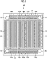
- FIG. 3 illustrates such a first layer (10).
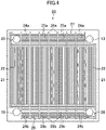
- FIG. 4 illustrates such a second layer (20). It should be noted that expressions used in the following description for indicating directions such as “upper,” “lower,” “left,” and “right” are just for the sake of convenience in explaining based on the drawings, but not for indicating how things are arranged or positioned actually in such directions.
- Each of the first and second layers (10, 20) is made of a rectangular metal plate member.
- the first and second layers (10, 20) are so configured that a number of grooves are provided within a peripheral portion (11, 21) on one side of the first or second layer (10, 20) by mechanical processing or etching, as described later. These grooves form pores when openings of the grooves are sealed by laminating the first layer (10), second layer (20), or end plate (31) on the first or second layer (10, 20).
- both the grooves of the first and second layers (10, 20) still open and the pores formed by sealing the openings thereof are referred to as "microchannels" or "flow channels.”
- the first layer (10) has a plurality of grooves in a middle portion thereof in the up-down direction as illustrated in FIG. 3 in such way that the plurality of grooves are aligned side by side in the right-left direction to extend straightly in the up-down direction.
- the plurality of grooves constitute a plurality of first flow channels (12) of the first layer (10).
- the second layer (20) has a plurality of grooves in a middle portion thereof in the up-down direction as illustrated in FIG. 4 in such way that the plurality of grooves are aligned side by side in the right-left direction to extend straightly in the up-down direction.
- the plurality of grooves constitute a plurality of second flow channels (22) of the second layer (20). As illustrated in FIG.
- the grooves constituting the first and second flow channels (12, 22) are rectangular in cross section. Moreover, the grooves constituting the first and second flow channels (12, 22) are not less than 10 ⁇ m but not more than 1000 ⁇ m in dimensions (D 1 , D 2 ) in the lamination direction of the first and second layers (10, 20) and in width dimensions (W 1 , W 2 ) in a direction perpendicular to the lamination direction. Thus, both the first and second flow channels (12, 22) are microchannels.
- the dimensional configurations of the first and second flow channels (12, 22) may be identical with each other or different from each other.
- the first layer (10) has a first gas transport section (13) and a second gas transport section (23) respectively at an upper right corner portion and at an upper left corner portion of the first layer (10) on one-end side (upper side) with respect to the plurality of first flow channels (12) in the up-down direction, and the first gas transport section (13) and the second gas transport section (23) penetrate the first layer (10) in the thickness direction.
- first gas transport section (13) is provided on the upper side with respect to the plurality of first flow channels (12)
- short ridges (14a) being rectangular in cross section and extending in the right-left direction are provided in tandem in the right-left direction with gaps therebetween and aligned side by side in the up-down direction with gaps therebetween.
- first microchannel A (15a) Between ridges (14a) neighboring with each other in the up-down direction, a groove is formed, which has a rectangular cross section and extends straightly in the right-left direction perpendicular to the up-down direction in which the plurality of first flow channels (12) extend, as illustrated in FIG. 6 .
- This groove constitutes a first microchannel A (15a).
- These first microchannels A (15a) are in fluid communication with each other not only in the right-left direction but also in the up-down direction through the gaps formed between neighboring ridges (14a) neighbored in the right-left direction. Such gaps between the ridges (14a) constitute first bypass flow channels A (16a).
- the first layer (10) includes a first one end-side collective flow channel (17) on the upper side with respect to the plurality of first flow channels (12), the first one end-side collective flow channel (17) including the first microchannels A (15a) and the first bypass flow channels A (16a) and being in fluid communication with one ends of the first flow channels (12). Because the first gas transport section (13) is provided in the region where the first one end-side collective flow channel (17) is provided, the first one end-side collective flow channel (17) will maintain the fluid communication with the first gas transport section (13) even after the opening of the first one end-side collective flow channel (17) is sealed with the second layer (20) or the end plate (31). Thus, the first one end-side collective flow channel (17) constitutes a first gas flow channel.
- the first one end-side collective flow channel (17) will be blocked from the second gas transport section (23) when the opening of the first one end-side collective flow channel (17) is sealed with the second layer (20) or the end plate (31).
- the first layer (10) has a first liquid transport section (18) and a second liquid transport section (28) respectively at a lower left corner portion and at a lower right corner portion of the first layer (10) on the other-end side (lower side) with respect to the plurality of first flow channels (12) in the up-down direction, and the first liquid transport section (18) and the second liquid transport section (28) penetrate the first layer (10) in the thickness direction.
- first liquid transport section (18) is provided on the lower side with respect to the plurality of first flow channels (12)
- short ridges (14b) being rectangular in cross section and extending in the right-left direction are provided in tandem in the right-left direction with gaps therebetween and aligned side by side in the up-down direction with gaps therebetween.
- first microchannel B 15b
- first microchannel B 15b
- These first microchannels B (15b) are in fluid communication with each other not only in the right-left direction but also in the up-down direction through the gaps formed between neighboring ridges (14b) neighbored in the right-left direction.
- gaps between the ridges (14b) constitute first bypass flow channels B (16b).
- the first layer (10) includes a first other end-side collective flow channel (19) on the lower side with respect to the plurality of first flow channels (12), the first other end-side collective flow channel (19) including the first microchannels B (15b) and the first bypass flow channels B (16b) and being in fluid communication with the other ends of the first flow channels (12). Because the first liquid transport section (18) is provided in the region where the first other end-side collective flow channel (19) is provided, the first other end-side collective flow channel (19) will maintain the fluid communication with the first liquid transport section (18) even after the opening of the first other end-side collective flow channel (19) is sealed with the second layer (20) or the end plate (31). Thus, the first other end-side collective flow channel (19) constitutes a first liquid flow channel.
- the first other end-side collective flow channel (19) will be blocked from the second liquid transport section (28) when the opening of the first other end-side collective flow channel (19) is sealed with the second layer (20) or the end plate (31).
- the second layer (20) includes a first gas transport section (13) and a second gas transport section (23) respectively at an upper right corner portion and at an upper left corner portion of the second layer (20) on the one-end side (upper side) with respect to the plurality of second flow channels (22) in the up-down direction, and the first gas transport section (13) and the second gas transport section (23) penetrate the second layer (20) in the thickness direction.
- short ridges (24a) being rectangular in cross section and extending in the right-left direction are provided in tandem in the right-left direction with gaps therebetween and aligned side by side in the up-down direction with gaps therebetween.
- a groove is formed, which has a rectangular cross section and extends straightly in the right-left direction perpendicular to the up-down direction in which the plurality of second flow channels (22) extend, as illustrated in FIG. 6 .
- This groove constitutes a second microchannel A (25a).
- These second microchannels A (25a) are in fluid communication with each other not only in the right-left direction but also in the up-down direction through the gaps formed between neighboring ridges (24a) neighbored in the right-left direction.
- Such gaps between the ridges (24a) constitute second bypass flow channels A (26a).
- the second layer (20) includes a second one end-side collective flow channel (27) on the upper side with respect to the plurality of second flow channels (22), the second one end-side collective flow channel (27) including the second microchannels A (25a) and the second bypass flow channels A (26a) and being in fluid communication with one ends of the second flow channels (22).
- the second gas transport section (23) is provided in the region where the second one end-side collective flow channel (27) is provided, the second one end-side collective flow channel (27) will maintain the fluid communication with the second gas transport section (23) even after the opening of the second one end-side collective flow channel (27) is sealed with the first layer (10).
- the second one end-side collective flow channel (27) constitutes a second gas flow channel.
- the second one end-side collective flow channel (27) will be blocked from the first gas transport section (13) when the opening of the second one end-side collective flow channel (27) is sealed with the first layer (10).
- the second layer (20) includes a first liquid transport section (18) and a second liquid transport section (28) respectively at a lower left corner portion and at a lower right corner portion of the second layer (20) on the other-end side (lower side) with respect to the plurality of second flow channels (22) in the up-down direction, and the first liquid transport section (18) and the second liquid transport section (28) penetrate the second layer (20) in the thickness direction.
- short ridges (24b) being rectangular in cross section and extending in the right-left direction are provided in tandem in the right-left direction with gaps therebetween and aligned side by side in the up-down direction with gaps therebetween.
- a groove is formed, which has a rectangular cross section and extends straightly in the right-left direction perpendicular to the up-down direction in which the plurality of second flow channels (22) extend, as illustrated in FIG. 7 .
- This groove constitutes a second microchannel B (25b).
- These second microchannels B (25b) are in fluid communication with each other not only in the right-left direction but also in the up-down direction through the gaps formed between neighboring ridges (24b) neighbored in the right-left direction.
- Such gaps between the ridges (24b) constitute second bypass flow channels B (26b).
- the second layer (20) includes a second other end-side collective flow channel (29) on the lower side with respect to the plurality of second flow channels (22), the second other end-side collective flow channel (29) including the second microchannels B (25b) and the second bypass flow channels B (26b) and being in fluid communication with the other ends of the second flow channels (22).
- the second liquid transport section (28) is provided in the region where the second other end-side collective flow channel (29) is provided, the second other end-side collective flow channel (29) will maintain the fluid communication with the second liquid transport section (28) even after the opening of the second other end-side collective flow channel (29) is sealed with the first layer (10).
- the second other end-side collective flow channel (29) constitutes a second liquid flow channel.
- the second other end-side collective flow channel (29) will be blocked from the first liquid transport section (18) when the opening of the second other end-side collective flow channel (29) is sealed with the first layer (10).
- the first microchannels A (15a) of the first one end-side collective flow channel (17) and the first microchannels B (15b) of the first other end-side collective flow channel (19) of the first layer (10) are not less than 10 ⁇ m but not more than 1000 ⁇ m both in dimensions (D A1 , D B1 ) in the lamination direction of the first and second layers (10, 20) and in width dimensions (W A1 , W B1 ) in a direction perpendicular to the lamination direction.
- the dimensional configurations of the first microchannels A and B (15a, 15b) may be identical with the first flow channels (12) or different from the first flow channels (12).
- the first microchannels A and B (15a, 15b) may be preferably configured such that the dimensions (D A1 , D B1 ) in the lamination direction of the first and second layers (10, 20) are equal to that of the first flow channels (12) and the width dimensions (W A1 , W B1 ) in the direction perpendicular to the lamination direction are equal to that of the first flow channels (12) as illustrated in FIG. 3 , or greater than that of the first flow channels (12) as illustrated in FIG.
- first bypass flow channels A and B (16a, 16b) may be microchannels.
- the second microchannels A (25a) of the second one end-side collective flow channel (27) and the second microchannels B (25b) of the second other end-side collective flow channel (29) of the second layer (20) are such that dimensions (D A2 , D B2 ) in the lamination direction of the first and second layers (10, 20) and width dimensions (W A2 , W B2 ) in the direction perpendicular to the lamination direction are not less than 10 ⁇ m but not more than 1000 ⁇ m.
- the dimensional configurations of the second microchannels A and B (25a, 25b) may be identical with the second flow channels (22) or different from the second flow channels (22).
- the second microchannels A and B (25a, 25b) may be preferably configured such that the dimensions (D A2 , D B2 ) in the lamination direction of the first and second layers (10, 20) are equal to that of the second flow channels (22) and the width dimensions (W A2 , W B2 ) in the direction perpendicular to the lamination direction are equal to that of the second flow channels (22) as illustrated in FIG. 4 , or greater than that of the second flow channels (22) as illustrated in FIG.
- dimensional ratios of the width dimensions (W A2 , W B2 ) of the second microchannels A and B (25a, 25b) with respect to that of the second flow channels (22) be one time or more but three times or less.
- the second bypass channels A and B (26a, 26b) may be microchannels.
- the first layer (10) may be produced in such a way that both the first flow channels (12) and the first microchannels A and B (15a, 15b) are fabricated at the same time because the first flow channels (12) and the first microchannels A and B (15a, 15b) are all microchannels.
- the second layer (20) may be produced in such a way that both the second flow channels (22) and the second microchannels A and B (25a, 25b) are fabricated at the same time because the second flow channels (22) and the second microchannels A and B (25a, 25b) are all microchannels.
- first gas transport sections (13), the second gas transport sections (23), the first liquid transport sections (18), and the second liquid transport sections (28) of the first and second layers (10, 20) thus laminated are sequentially joined to form tubular geometries, respectively.
- the tubular geometries formed with the first gas transport sections (13) and the first liquid transport sections (18) are in fluid communication with the flow channels in the first layer (10) but not with the flow channels in the second layer (20). Therefore, after supplied to one of the tubular geometries formed by the first gas transport sections (13) or the first liquid transport sections (18), the first fluid is distributed to the first layers (10) but not to the second layers (20), so that the first fluid flows through the first flow channels (12), the first one end-side collective flow channel (17), and the first other end-side collective flow channel (19) inside the first layers (10), and merges at the other side and flows out collectively from the first layers (10).
- the tubular geometries formed from the second gas transport sections (23) and the second liquid transport sections (28) are in fluid communication with the flow channels in the second layer (20) but not with the flow channels in the first layer (10). Therefore, after supplied to one of the tubular geometries formed by the second gas transport sections (23) or the second liquid transport sections (28), the second fluid is distributed to the second layers (20) but not to the first layers (10), so that the second fluid flows through the second flow channels (22), the second one end-side collective flow channel (27), and the second other end-side collective flow channel (29) inside the second layers (20), and merges at the other side and flows out collectively from the second layers (20).
- the alternating lamination of the first and second layers (10, 20) is so configured that the first and second layers (10, 20) are laminated with each other in such a way that the first and second flow channels (12, 22) extend parallel to each other, as illustrated in Figure 2 .
- the first fluid in the first flow channels (12) of the first layer (10) and the second fluid in the second flow channels (22) of the second layer (20) flow in opposite directions in the plan view.
- the alternating lamination of the first and second layers (10, 20) may be so configured that the first and second layers (10, 20) are laminated with each other in such a way that the first and second flow channels (12, 22) extend perpendicularly to each other, as illustrated in Figure 10 .
- the first fluid in the first flow channels (12) of the first layer (10) and the second fluid in the second flow channels (22) of the second layer (20) flow in directions perpendicular to each other in the plan view.
- the pair of end plates (31, 32) is constituted by a rectangular metal plate member, which has a shape identical with those of the first and second layers (10, 20).
- the end plate (31), which is one of the pair, is laminated on one side of the alternating lamination of the first and second layers (10, 20).
- the end plate (31) has four pores (31a, 31b, 31c, 31d), which correspond to the tubular geometries formed with the first gas transport sections (13), the second gas transport sections (23), the first liquid transport sections (18), and the second liquid transport sections (28) of the first and second layers (10, 20), respectively, and the four pores (31a, 31b, 31c, 31d) are connected with a first gas inlet/outlet pipe (33), a second gas inlet/outlet pipe (34), a first liquid inlet/outlet pipe (35), and a second liquid inlet/outlet pipe (36), respectively.
- the end plate (32), which is the other one of the pair, is laminated on the other side of the alternating lamination of the first and second layers (10, 20) to seal the tubular geometries formed with the first gas transport sections (13), the second gas transport sections (23), the first liquid transport sections (18), and the second liquid transport sections (28).
- Each of the first and second fluids for flowing in the first and second layers (10, 20) may be preferably a CFC refrigerant or a natural refrigerant, independently.
- the CFC refrigerant include R410A, R32, R134a, HFO, and the like.
- the natural refrigerant include CO 2 , hydrocarbon such as propane, and the like.
- the heat exchanger (100) according to the first embodiment with the configuration described above is such that, in each first layer (10), the first one end-side collective flow channel (17) and the first other end-side collective flow channel (19) are in fluid communication with the plurality of first flow channels (12), which are microchannels, and one of the first one end-side collective flow channel (17) or the first other end-side collective flow channel (19) is for distributively supplying the first fluid to the first flow channels (12), and the other one of the first one end-side collective flow channel (17) or the first other end-side collective flow channel (19) is for merging the first fluid flowing out from the first flow channels (12) so as to let the first fluid flow out collectively from the first layer (10).
- the first gas transport section (13) supplies the first fluid containing the gas as the condensation source to the first one end-side collective flow channel (17), the first one end-side collective flow channel (17) distributively supplies the first fluid to the plurality of first flow channels (12), the gas is then condensed in the plurality of first flow channels (12), and the first other end-side collective flow channel (19) merges the first fluid thus condensed and flowed out from the plurality of first flow channels (12), so as to let the first fluid flow out collectively via the first liquid transport section (18).
- the first liquid transport section (18) supplies the first fluid containing the liquid as the evaporation source to the first other end-side collective flow channel (19), the first other end-side collective flow channel (19) distributively supplies the first fluid to the plurality of first flow channels (12), the liquid is then evaporated in the plurality of first flow channels (12), and the first one end-side collective flow channel (17) merges the first fluid thus evaporated and flowed out from the plurality of first flow channels (12), so as to let the first fluid flow out collectively via the first gas transport section (13).
- first one end-side collective flow channel (17) and the first other end-side collective flow channel (19) include the first microchannels A and B (15a, 15b), respectively, the first microchannels A and B (15a, 15b) extending in the right-left direction perpendicular to (or crossing) the up-down direction in which the plurality of first flow channels (12) extend.
- each second layer (20) is configured such that the second one end-side collective flow channel (27) and the second other end-side collective flow channel (29) are in fluid communication with a plurality of second flow channels (22), which are microchannels, and one of the second one end-side collective flow channel (27) or the second other end-side collective flow channel (29) is for distributively supplying the second fluid to the plurality of second flow channels (22) and the other one of the second one end-side collective flow channel (27) or the second other end-side collective flow channel (29) is for merging the second fluid flowing out from the plurality of second flow channels (22) so as to let the fluid flow out collectively from the second layer (20).
- the second gas transport section (23) supplies the second fluid containing the gas as the condensation source to the second one end-side collective flow channel (27), the second one end-side collective flow channel (27) distributively supplies the second fluid to the plurality of second flow channels (22), the gas is then condensed in the plurality of second flow channels (22), and the second other end-side collective flow channel (29) merges the second fluid thus condensed and flowed out from the second flow channels (22), so as to let the second fluid flow out collectively via the second liquid transport section (28).
- the second liquid transport section (28) supplies the second fluid containing the liquid as the evaporation source to the second other end-side collective flow channel (29), the second other end-side collective flow channel (29) distributively supplies the second fluid to the plurality of second flow channels (22), the liquid is then evaporated in the plurality of second flow channels (22), and the second one end-side collective flow channel (27) merges the second fluid thus evaporated and flowed out from the second flow channels (22), so as to let the second fluid flow out collectively via the second gas transport section (23).
- the second one end-side collective flow channel (27) and the second other end-side collective flow channel (29) include second microchannels A and B (25a, 25b), respectively, the second microchannels A and B (25a, 25b) extending in the right-left direction perpendicular to (or crossing) the up-down direction in which the plurality of second flow channels (22) extend.
- FIG. 11 illustrates one example of a heat pump system (40) including the heat exchanger (100) according to the first embodiment as a cascade condenser.
- the heat pump system (40) includes an outdoor unit (41) including the heat exchanger (100) according to the first embodiment and a plurality of indoor units (42). Furthermore, the heat pump system (40) includes first and second refrigerant circuits (50, 60).
- the first refrigerant circuit (50) is provided in the outdoor unit (41) and is configured such that one end and the other end of the first refrigerant circuit (50) are connected with the first gas inlet/outlet pipe (33) and the first liquid inlet/outlet pipe (35) of the heat exchanger (100) according to the first embodiment, respectively.
- the first refrigerant circuit (50) includes an outdoor air heat exchanger (51).
- the first refrigerant circuit (50) is such that a flow channel switching structure is provided between a joint portion with the first gas inlet/outlet pipe (33) and the outdoor air heat exchanger (51), the flow channel switching structure including a first compressor (52) and a first four-way switching valve (53).
- the first refrigerant circuit (50) is such that a first expansion valve (54) is provided between a joint portion with the first liquid inlet/outlet pipe (35) and the outdoor air heat exchanger (51).
- the second refrigerant circuit (60) is provided such that the second refrigerant circuit (60) extends out of the outdoor unit (41), branches out to run through the respective indoor units (42), merges after coming out from the indoor units (42), and returns to the outdoor unit (41), and one end and the other end of the second refrigerant circuit (60) are connected with the second gas inlet/outlet pipe (34) and the second liquid inlet/outlet pipe (36) of the heat exchanger (100) according to the first embodiment, respectively.
- the second refrigerant circuit (60) includes an indoor air heat exchanger (61) inside each indoor unit (42).
- the second refrigerant circuit (60) is such that, inside the outdoor unit (41), a flow channel switching structure is provided between a joint portion with the second gas inlet/outlet pipe (34) and a portion extending toward the indoor air heat exchangers (61) in the indoor units (42), the flow channel switching structure including a second compressor (62) and a second four-way switching valve (63).
- the second refrigerant circuit (60) is such that, between a joint portion with the second liquid inlet/outlet pipe (36) and the portion extending toward the indoor air heat exchangers (61) inside the indoor units (42), a second outdoor expansion valve (64) is provided in the outdoor unit (41) and a second indoor expansion valve (65) is provided in each indoor unit (42).
- cooling operation of the indoor units (42) is carried out in such a way that the first four-way switching valve (53) switches over the flow channel so that a first refrigerant (first fluid), which has been boosted in pressure and temperature by the first compressor (52), is sent to the outdoor air heat exchanger (51).
- the first refrigerant thus sent to the outdoor air heat exchanger (51) releases heat to condense in the outdoor air heat exchanger (51) through heat exchange with outdoor air.
- the first refrigerant thus condensed in the outdoor air heat exchanger (51) is sent to the heat exchanger (100) according to the first embodiment after depressurized by the first expansion valve (54).
- the second four-way switching valve (63) switches over the flow channel so that a second refrigerant (second fluid), which has been boosted in pressure and temperature by the second compressor (62), is sent to the heat exchanger (100) according to the first embodiment.
- the first refrigerant flows thereinto via the first liquid inlet/outlet pipe (35) and is distributed to the plurality of first layers (10), in each of which the first refrigerant flows through the plurality of first flow channels (12) via the first other end-side collective flow channel (19).
- the second refrigerant flows into the heat exchanger (100) according to the first embodiment via the second gas inlet/outlet pipe (34) and is distributed to the plurality of second layers (20), in each of which the second refrigerant flows through the plurality of second flow channels (22) via the second one end-side collective flow channel (27).
- the heat exchange takes place between the first and second layers (10, 20), thereby causing the first refrigerant to absorb heat to evaporate in the first layers (10), while causing the second refrigerant to release the heat to condense in the second layers (20).
- the first refrigerant thus evaporated in the first layers (10) flows through the first one end-side collective flow channel (17) and flows out via the first gas inlet/outlet pipe (33).
- the second refrigerant thus condensed in the second layers (20) flows through the second other end-side collective flow channel (29) and flows out via the second liquid inlet/outlet pipe (36).
- the first refrigerant thus flowed out via the first gas inlet/outlet pipe (33) is sucked into the first compressor (52) via the first four-way switching valve (53) and boosted in pressure by the first compressor (52) again and sent to the outdoor air heat exchanger (51).
- the second refrigerant thus flowed out via the second liquid inlet/outlet pipe (36) flows through the second outdoor expansion valve (64) in the outdoor unit (41) and is sent out from the outdoor unit (41) to the respective indoor units (42).
- the second refrigerant thus sent to the respective indoor units (42) is depressurized by the second indoor expansion valve (65) and sent to the indoor air heat exchanger (61), in which the second refrigerant absorbs heat to evaporate via heat exchange with indoor air. In this way, the indoor air is cooled down.
- the second refrigerant thus evaporated in the indoor air heat exchanger (61) is returned to the outdoor unit (41) from the indoor units (42) and sucked into the second compressor (62) via the second four-way switching valve (63), and is boosted in pressure by the second compressor (62) again and sent to the heat exchanger (100) according to the first embodiment.
- heating operation of the indoor units (42) is carried out in such a way that the first four-way switching valve (53) switches over the flow channel so that the first refrigerant, which has been boosted in pressure and temperature by the first compressor (52), is sent to the heat exchanger (100) according to the first embodiment.
- the second four-way switching valve (63) switches over the flow channel so that the second refrigerant, which has been boosted in pressure and temperature by the second compressor (62), is sent from the outdoor unit (41) to the indoor air heat exchangers (61) of the indoor units (42).
- the second refrigerant thus sent to the indoor air heat exchanger (61) releases heat to condense in the indoor air heat exchanger (61) through heat exchange with the indoor air.
- the second refrigerant thus condensed in the indoor air heat exchanger (61) is depressurized by the second indoor expansion valves (65) in the indoor units (42) and is returned from the indoor units (42) to the outdoor unit (41).
- the second refrigerant thus returned to the outdoor unit (41) is sent to the heat exchanger (100) according to the first embodiment after depressurized by the second outdoor expansion valve (64) in the outdoor unit (41).
- the first refrigerant flows thereinto via the first gas inlet/outlet pipe (33) and is distributed to the plurality of first layers (10), in each of which the first refrigerant flows through the plurality of first flow channels (12) via the first one end-side collective flow channel (17).
- the second refrigerant flows into the heat exchanger (100) according to the first embodiment via the second liquid inlet/outlet pipe (36) and is distributed to the plurality of second layers (20), in each of which the second refrigerant flows through the plurality of second flow channels (22) via the second other end-side collective flow channel (29).
- the heat exchange takes place between the first and second layers (10, 20), thereby causing the first refrigerant to release heat to condense in the first layers (10) while causing the second refrigerant to absorb the heat to evaporate in the second layers (20).
- the first refrigerant thus condensed in the first layers (10) flows through the first other end-side collective flow channel (19) and flows out via the first liquid inlet/outlet pipe (35).
- the second refrigerant thus evaporated in the second layers (20) flows through the second one end-side collective flow channel (27) and flows out via the second liquid inlet/outlet pipe (36).
- the first refrigerant thus flowed out via the first liquid inlet/outlet pipe (35) is sent to the outdoor air heat exchanger (51) after depressurized by the first expansion valve (54), and absorbs heat to evaporate in the outdoor air heat exchanger (51) through heat exchange with the outdoor air.
- the first refrigerant thus evaporated in the outdoor air heat exchanger (51) is sucked into the first compressor (52) via the first four-way switching valve (53), and boosted in pressure by the first compressor (52) again and sent to the heat exchanger (100) according to the first embodiment.
- the second refrigerant thus flowed out via the second gas inlet/outlet pipe (34) is sucked into the second compressor (62) via the second four-way switching valve (63), and boosted in pressure by the second compressor (62) again and sent to the respective indoor units (42).
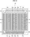
- FIG. 12 illustrates a first layer (10) of a heat exchanger (100) according to a second embodiment.
- FIG. 13 illustrates a second layer (20) thereof.
- Like references used in the first embodiment are used for like parts herein.
- a first one end-side collective flow channel (17) constitutes a gas flow channel, and therefore first microchannels A (15a) serve as gas flow channels (first gas flow channels) as well in the first layers (10).
- a first other end-side collective flow channel (19) functions as a liquid flow channel herein, and therefore first microchannels B (15b) serve as liquid flow channels (first liquid flow channels) as well.
- the first microchannels A and B (15a, 15b) are identical with each other in dimensions (D A1 , D B1 ) in the lamination direction of the first and second layers (10, 20).
- a width dimension (W A1 ) of the first microchannels A (15a) is greater than a width dimension (W B1 ) of the first microchannels B (15b). Therefore, the first microchannels A (15a) serving as the first gas flow channels are greater than the first microchannels B (15b) serving as the first liquid flow channels in terms of flow channel cross-sectional area (D A1 ⁇ W A1 > D B1 ⁇ W B1 ). For this reason, the first one end-side collective flow channel (17) has a capacity greater than that of the first other end-side collective flow channel (19).
- the second one end-side collective flow channel (27) constitutes a gas flow channel, and therefore second microchannels A (25a) serve as gas flow channels (second gas flow channels) as well.
- the second other end-side collective flow channel (29) functions as a liquid flow channel herein, and therefore the second microchannels B (25b) serve as liquid flow channels (second liquid flow channels) as well.
- the second microchannels A and B (25a, 25b) are identical with each other in dimensions (D A2 , D B2 ) in the lamination direction of the first and second layers (10, 20).
- a width dimension (W A2 ) of the second microchannels A (25a) is greater than a width dimension (W B2 ) of the second microchannels B (25b).
- the second microchannels A (25a) serving as the second gas flow channels are greater than the second microchannels B (25b) serving as the second liquid flow channels in terms of the flow channel cross-sectional area (D A2 ⁇ W A2 > D B2 ⁇ W B2 ).
- the second one end-side collective flow channel (27) has a greater capacity than that of the second other end-side collective flow channel (29).
- the first microchannels A (15a) serving as the first gas flow channels are greater than the first microchannels B (15b) serving as the first liquid flow channels in terms of the flow channel cross-sectional area.
- the second microchannels A (25a) serving as the second gas flow channels are greater than the second microchannels B (25b) serving as the second liquid flow channels in terms of the flow channel cross-sectional area.
- this configuration in which the flow channel cross-sectional areas of the first and second gas flow channels are greater than those of the first and second liquid flow channels makes it possible to avoid an excessively large pressure loss that would be caused due to a high rate of the gas or gas-liquid mixture fluid flowing in the first and second gas flow channels.
- This embodiment is the same as or similar to the first embodiment in terms of the other configurations, and can attain the advantages same as or similar to those of the first embodiment.
- FIG. 14 illustrates a first layer (10) of a heat exchanger (100) according to a third embodiment.
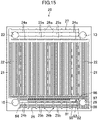
- FIG. 15 illustrates a second layer (20) thereof.
- Like references used in the first embodiment are used for like parts herein.
- the first layers (10) are configured such that a first other end-side collective flow channel (19) is provided with a first long ridge (71) extending in the right-left direction and having a rectangular cross section.
- the first long ridge (71) divides the region, in which first microchannels B (15b) are provided, into two parts aligned in the up-down direction.
- a first longitudinal ridge (72) is provided, which extends from a peripheral portion (11) in the up-down direction and has a rectangular cross section.
- the first longitudinal ridge (72) serves as a partition by which the first liquid transport section (18) is parted in the right-left direction from the region in which the first microchannels B (15b) are provided.
- the first longitudinal ridge (72) is provided with a first small ridge (73) at a position corresponding to the first long ridge (71) in the up-down direction of the first longitudinal ridge (72), the first small ridge (73) extending rightward from the first longitudinal ridge (72) toward the first long ridge (71) and having a rectangular cross section.
- a first right-side flowable section (74) is provided, which provides up-down directional fluid communication between the parts divided by the first long ridge (71).
- a first left-side flowable section (75) is provided between the first long ridge (71) and the first small ridge (73), the first left-side flowable section (75) providing up-down directional fluid communication between the parts divided by the first long ridge (71).
- the first right-side flowable section (74) has a greater flow channel cross-sectional area than the first left-side flowable section (75).
- a first lateral ridge (76) extending in the right-left direction and having a rectangular cross section is provided.
- the first lateral ridge (76) serves as a partition by which the first liquid transport section (18) is parted in the up-down direction from the region in which the first flow channels (12) are provided, and the first lateral ridge (76) is positioned in a T shape-like orientation with the first longitudinal ridge (72) when viewed in the plan view.
- the left and right sides of the first lateral ridge (76) are open in the up-down direction for fluid communication.
- a first liquid ejecting section (77) which is a gap, is formed between a tip of the first longitudinal ridge (72) and the first lateral ridge (76).
- the first liquid ejecting section (77) provides right-left directional fluid communication between the region in which the first liquid transport section (18) is provided and the upper one of the parts divided by the first long ridge (71).
- a plurality of first columnar structures (78) are provided, each of which has a square shape when viewed in the plan view.
- the plurality of first columnar structures (78) are arranged to form a square lattice when viewed in the plan view, thereby forming first microchannels B (15b) between the first columnar structures (78).
- Some of the first columnar structures (78) are integrated with the first longitudinal ridge (72).
- a first fluid containing the liquid as the evaporation source is supplied to the first other end-side collective flow channel (19) via the first liquid transport section (18).
- the first fluid flows in such a way that the first fluid is ejected from the first liquid ejecting section (77) rightward along the direction in which the plurality of first flow channels (12) are arranged side by side into the upper one of parts divided by the first long ridge (71).
- Part of the first fluid flows into the first flow channels (12) and the rest of the first fluid flows via the first right-side flowable section (74) into the lower one of the parts divided by the first long ridge (71).
- the first fluid flows in such a way that the first fluid is redirected to flow leftward in the direction in which the plurality of first flow channels (12) are arranged side by side, and the first fluid is ejected from the first left-side flowable section (75) into the upper one of the parts divided by the first long ridge (71), because the first right-side flowable section (74) has a greater flow channel cross-sectional area than the first left-side flowable section (75).
- a second long ridge (81) extending in the right-left direction and having a rectangular cross section is provided in the second other end-side collective flow channel (29).
- the second long ridge (81) divides the region, in which the second microchannels B (25b) are provided, into two parts aligned in the up-down direction.
- a second longitudinal ridge (82) is provided, which extends from the peripheral portion (21) in the up-down direction and has a rectangular cross section.
- the second longitudinal ridge (82) serves as a partition by which the second liquid transport section (28) is parted in the right-left direction from the region in which the second microchannels B (25b) are provided.
- the second longitudinal ridge (82) is provided with a second small ridge (83) at a position corresponding to the second long ridge (81) in the up-down direction of the second longitudinal ridge (82), the second small ridge (83) extending leftward from the second longitudinal ridge (82) toward the second long ridge (81) and having a rectangular cross section.
- a second left-side flowable section (84) is provided, which provides up-down directional fluid communication between the parts divided by the second long ridge (81).
- a second right-side flowable section (85) is provided between the second long ridge (81) and the second small ridge (83), the second right-side flowable section (85) providing up-down directional fluid communication between the parts divided by the second long ridge (81).
- the second left-side flowable section (84) has a greater flow channel cross-sectional area than the second right-side flowable section (85).
- a second lateral ridge (86) extending in the right-left direction and having a rectangular cross section is provided on the upper side of the second liquid transport section (28).
- the second lateral ridge (86) serves as a partition by which the second liquid transport section (28) is parted in the up-down direction from the region in which the second flow channels (22) are provided, and the second lateral ridge (86) is positioned in a T shape-like orientation with the second longitudinal ridge (82) when viewed in the plan view.
- the left and right sides of the second lateral ridge (86) are open in the up-down direction for fluid communication.
- a second liquid ejecting section (87), which is a gap, is formed between a tip of the second longitudinal ridge (82) and the second lateral ridge (86).
- the second liquid ejecting section (87) provides right-left directional fluid communication between the region in which the second liquid transport section (28) is provided and the upper one of the parts divided by the second long ridge (81).
- a plurality of second columnar structures (88) are provided, each of which has a square shape when viewed in the plan view.
- the plurality of second columnar structures (88) are arranged to form a square lattice when viewed in the plan view, thereby forming microchannels between the second columnar structures (88).
- Some of the second columnar structures (88) are integrated with the second longitudinal ridge (82).
- a second fluid containing the liquid as the evaporation source is supplied to the second other end-side collective flow channel (29) via the second liquid transport section (28).
- the second fluid flows in such a way that the second fluid is ejected from the second liquid ejecting section (87) leftward in the direction in which the plurality of second flow channels (22) are arranged side by side into the upper one of parts divided by the second long ridge (81).
- Part of the second fluid flows into the second flow channels (22) and the rest of the second fluid flows from the second left-side flowable section (84) into the lower one of the parts divided by the second long ridge (81).
- the second fluid flows in such a way that the second fluid is redirected to flow rightward in the direction in which the plurality of second flow channels (22) are arranged side by side, and the second fluid is ejected from the second right-side flowable section (85) into the upper one of the parts divided by the second long ridge (81), because the second left-side flowable section (84) has a greater flow channel cross-sectional area than the second right-side flowable section (85).
- the heat exchanger (100) according to the third embodiment with the configuration described above is such that such a redirecting structure is provided in each of the first other end-side collective flow channel (19) for supplying into the first flow channels (12) the first fluid containing the liquid as the evaporation source and the second other end-side collective flow channel (29) for supplying into the second flow channels (22) the second fluid containing the liquid as the evaporation source.
- the redirecting structure guides the first fluid containing the liquid as the evaporation source in such a way that the first fluid flows in one way in the direction in which the plurality of first flow channels (12) are arranged side by side, and, after that, the first fluid is redirected to flow in the other way to remerge into the flow flowing in the one way, so that the first fluid becomes uniform along the direction in which the plurality of first flow channels (12) are arranged side by side.
- the redirecting structure guides the second fluid containing the liquid as the evaporation source in such a way that the second fluid flows in one way in the direction in which the plurality of second flow channels (22) are arranged side by side, and, after that, the second fluid is redirected to flow in the other way to remerge into the flow flowing in the one way, so that the second fluid becomes uniform along the direction in which the plurality of second flow channels (22) are arranged side by side.
- This embodiment is the same as or similar to the second embodiment in terms of the other configurations, and can attain the advantages same as or similar to those of the second embodiment.
- the first to third embodiments are so configured that the first microchannels A and B (15a, 15b) extend in the right-left direction perpendicular to the up-down direction in which the plurality of first flow channels (12) extend and the second microchannels A and B (25a, 25b) extend in the right-left direction perpendicular to the up-down direction in which the plurality of second flow channels (22) extend, but the present disclosure is not limited to such configurations and may be differently configured, provided that the first microchannels A and B (15a, 15b) extend in a direction crossing a direction in which the plurality of first flow channels (12) extend, and the second microchannels A and B (25a, 25b) extend in a direction crossing a direction in which the plurality of second flow channels (22) extend.
- the first to third embodiments are so configured that the first microchannels A and B (15a, 15b) and the second microchannels A and B (25a, 25b) are configured as the grooves formed between the ridges (14a, 14b, 24a, 24b), but the present disclosure is not limited to such configurations and may be configured such that, for example as in the first layer (10) illustrated in FIGS. 16 and 17 , pluralities of columnar structures A and B (91a, 91b) are provided with gaps therebetween so as to form the first microchannels A and B (15a, 15b) between the columnar structures A and B (91a, 91b).
- first to third embodiments are so configured that the first and second flow channels (12, 22) and the like are rectangular in cross section, but the present disclosure is not limited to such configurations and may be configured such that the first and/or second flow channels (12, 22) and/or the like have a cross section of another shape such as semicircular cross sections.
- first to third embodiments are so configured that the first and second flow channels (12, 22) and the like extend straightly, but the present disclosure is not limited to such configurations and may be so configured that the first and/or second flow channels (12, 22) and/or the like extend meanderingly or zigzag.
- the present disclosure is applicable to the technical fields of heat exchangers and heat pump systems having the same.
Landscapes
- Engineering & Computer Science (AREA)
- Physics & Mathematics (AREA)
- Thermal Sciences (AREA)
- Mechanical Engineering (AREA)
- General Engineering & Computer Science (AREA)
- Heat-Exchange Devices With Radiators And Conduit Assemblies (AREA)
- Physical Or Chemical Processes And Apparatus (AREA)
Applications Claiming Priority (2)
| Application Number | Priority Date | Filing Date | Title |
|---|---|---|---|
| JP2020021016A JP6970360B2 (ja) | 2020-02-10 | 2020-02-10 | 熱交換器及びそれを有するヒートポンプシステム |
| PCT/JP2021/004958 WO2021162034A1 (ja) | 2020-02-10 | 2021-02-10 | 熱交換器及びそれを有するヒートポンプシステム |
Publications (3)
| Publication Number | Publication Date |
|---|---|
| EP4086554A1 true EP4086554A1 (de) | 2022-11-09 |
| EP4086554A4 EP4086554A4 (de) | 2023-03-15 |
| EP4086554B1 EP4086554B1 (de) | 2024-07-03 |
Family
ID=77292553
Family Applications (1)
| Application Number | Title | Priority Date | Filing Date |
|---|---|---|---|
| EP21754242.2A Active EP4086554B1 (de) | 2020-02-10 | 2021-02-10 | Wärmetauscher und wärmepumpensystem damit |
Country Status (4)
| Country | Link |
|---|---|
| US (1) | US11815316B2 (de) |
| EP (1) | EP4086554B1 (de) |
| JP (1) | JP6970360B2 (de) |
| WO (1) | WO2021162034A1 (de) |
Family Cites Families (19)
| Publication number | Priority date | Publication date | Assignee | Title |
|---|---|---|---|---|
| DE1601216B2 (de) * | 1967-11-03 | 1971-06-16 | Linde Ag, 6200 Wiesbaden | Blechtafel fuer platten waermetauscher mit einem stapel solcher blechtafeln |
| AU568940B2 (en) * | 1984-07-25 | 1988-01-14 | University Of Sydney, The | Plate type heat exchanger |
| JPS63210595A (ja) * | 1987-02-27 | 1988-09-01 | Ishikawajima Harima Heavy Ind Co Ltd | プレ−トフイン型熱交換器 |
| GB9104155D0 (en) * | 1991-02-27 | 1991-04-17 | Rolls Royce Plc | Heat exchanger |
| JP2004261911A (ja) | 2003-02-28 | 2004-09-24 | Mitsubishi Heavy Ind Ltd | チャンネル構造体及びその製造方法 |
| JP2007529707A (ja) * | 2004-02-24 | 2007-10-25 | スペグ カンパニー リミテッド | 燃料電池用マイクロ熱交換器及び製作方法 |
| US20070298486A1 (en) * | 2006-06-16 | 2007-12-27 | Velocys Inc. | Microchannel Apparatus and Methods Of Conducting Unit Operations With Disrupted Flow |
| KR100938802B1 (ko) * | 2009-06-11 | 2010-01-27 | 국방과학연구소 | 마이크로채널 열교환기 |
| US8801922B2 (en) * | 2009-06-24 | 2014-08-12 | State Of Oregon Acting By And Through The State Board Of Higher Education On Behalf Of Oregon State University | Dialysis system |
| WO2011013950A2 (ko) * | 2009-07-27 | 2011-02-03 | 한국델파이주식회사 | 플레이트 열교환기 |
| DE102009050500B4 (de) * | 2009-10-23 | 2011-06-30 | Voith Patent GmbH, 89522 | Wärmeübertragerplatte und Verdampfer mit einer solchen |
| KR101228418B1 (ko) * | 2012-03-07 | 2013-02-12 | 주식회사 코헥스 | 3차원 마이크로채널 판형 열교환기 및 이를 이용한 열교환 방법 |
| JP5749786B2 (ja) * | 2013-11-28 | 2015-07-15 | 株式会社前川製作所 | 熱交換器 |
| EP2910887B1 (de) * | 2014-02-21 | 2019-06-26 | Rolls-Royce Corporation | Mikrokanalwärmetauscher für gasturbinenzwischenkühlung und kondensation sowie korrespondierende methode |
| JP6184904B2 (ja) * | 2014-06-06 | 2017-08-23 | 東京瓦斯株式会社 | 隔離板式熱交換器 |
| CN107208979A (zh) * | 2014-10-01 | 2017-09-26 | 三菱重工压缩机有限公司 | 层叠板式热交换器 |
| CN106403688B (zh) * | 2016-10-31 | 2019-06-14 | 航天海鹰(哈尔滨)钛业有限公司 | 一种换热器芯部 |
| JP7045195B2 (ja) * | 2017-04-28 | 2022-03-31 | 株式会社前川製作所 | 熱交換器 |
| CN206944778U (zh) * | 2017-07-06 | 2018-01-30 | 湖南耽思科技有限公司 | 一种微通道换热器结构 |
-
2020
- 2020-02-10 JP JP2020021016A patent/JP6970360B2/ja active Active
-
2021
- 2021-02-10 EP EP21754242.2A patent/EP4086554B1/de active Active
- 2021-02-10 WO PCT/JP2021/004958 patent/WO2021162034A1/ja not_active Ceased
-
2022
- 2022-08-10 US US17/885,156 patent/US11815316B2/en active Active
Also Published As
| Publication number | Publication date |
|---|---|
| EP4086554A4 (de) | 2023-03-15 |
| EP4086554B1 (de) | 2024-07-03 |
| JP6970360B2 (ja) | 2021-11-24 |
| WO2021162034A1 (ja) | 2021-08-19 |
| US20220381519A1 (en) | 2022-12-01 |
| US11815316B2 (en) | 2023-11-14 |
| JP2021127843A (ja) | 2021-09-02 |
Similar Documents
| Publication | Publication Date | Title |
|---|---|---|
| EP3290851B1 (de) | Geschichtetes kopfteil, wärmetauscher und klimaanlage | |
| CN105074375A (zh) | 层叠型热交换器 | |
| JP6080982B2 (ja) | 積層型ヘッダー、熱交換器、及び、空気調和装置 | |
| CN104677170A (zh) | 热交换器及空调装置 | |
| EP3499169B1 (de) | Laminiertes kopfteil, wärmetauscher und kältekreislaufvorrichtung | |
| CN104995474A (zh) | 用于空气调节回路的具有制冷剂供给部的冷凝器 | |
| US10215498B2 (en) | Air guide-integrated evaporation cooler and method for manufacturing same | |
| CN109564070B (zh) | 热交换器和使用它的制冷系统 | |
| WO2017150126A1 (ja) | 熱交換器及び空気調和機 | |
| WO2015063875A1 (ja) | 積層型ヘッダー、熱交換器、及び、空気調和装置 | |
| WO2018074348A1 (ja) | 熱交換器およびそれを用いた冷凍システム | |
| CN109416229B (zh) | 热交换器和使用它的制冷装置 | |
| WO2018074343A1 (ja) | 熱交換器およびこれを用いた冷凍システム | |
| JP6906130B2 (ja) | 熱交換器およびそれを用いた冷凍システム | |
| US11619427B2 (en) | Heat exchanger and heat pump system having same | |
| CN117120794A (zh) | 热交换器 | |
| US20250362064A1 (en) | Heat exchanger and refrigeration apparatus | |
| EP4086554B1 (de) | Wärmetauscher und wärmepumpensystem damit | |
| JPWO2020090015A1 (ja) | 冷媒分配器、熱交換器および空気調和装置 | |
| WO2023275936A1 (ja) | 冷媒分配器、熱交換器及び冷凍サイクル装置 | |
| WO2021245901A1 (ja) | 冷媒分配器、熱交換器および空気調和装置 | |
| WO2018074346A1 (ja) | 熱交換器およびそれを用いた冷凍装置 | |
| WO2018074347A1 (ja) | 熱交換器およびそれを用いた冷凍システム | |
| CN113474600A (zh) | 热交换器以及制冷循环装置 | |
| JP6827186B2 (ja) | プレートフィン積層型熱交換器およびそれを用いた冷凍システム |
Legal Events
| Date | Code | Title | Description |
|---|---|---|---|
| STAA | Information on the status of an ep patent application or granted ep patent |
Free format text: STATUS: THE INTERNATIONAL PUBLICATION HAS BEEN MADE |
|
| PUAI | Public reference made under article 153(3) epc to a published international application that has entered the european phase |
Free format text: ORIGINAL CODE: 0009012 |
|
| STAA | Information on the status of an ep patent application or granted ep patent |
Free format text: STATUS: REQUEST FOR EXAMINATION WAS MADE |
|
| 17P | Request for examination filed |
Effective date: 20220801 |
|
| AK | Designated contracting states |
Kind code of ref document: A1 Designated state(s): AL AT BE BG CH CY CZ DE DK EE ES FI FR GB GR HR HU IE IS IT LI LT LU LV MC MK MT NL NO PL PT RO RS SE SI SK SM TR |
|
| RAP3 | Party data changed (applicant data changed or rights of an application transferred) |
Owner name: DAIKIN INDUSTRIES, LTD. |
|
| RIC1 | Information provided on ipc code assigned before grant |
Ipc: F25B 1/00 20060101ALI20221216BHEP Ipc: F28F 3/08 20060101ALI20221216BHEP Ipc: F28F 3/04 20060101ALI20221216BHEP Ipc: F28D 9/00 20060101AFI20221216BHEP |
|
| A4 | Supplementary search report drawn up and despatched |
Effective date: 20230213 |
|
| RIC1 | Information provided on ipc code assigned before grant |
Ipc: F25B 1/00 20060101ALI20230207BHEP Ipc: F28F 3/08 20060101ALI20230207BHEP Ipc: F28F 3/04 20060101ALI20230207BHEP Ipc: F28D 9/00 20060101AFI20230207BHEP |
|
| DAV | Request for validation of the european patent (deleted) | ||
| DAX | Request for extension of the european patent (deleted) | ||
| P01 | Opt-out of the competence of the unified patent court (upc) registered |
Effective date: 20230525 |
|
| STAA | Information on the status of an ep patent application or granted ep patent |
Free format text: STATUS: EXAMINATION IS IN PROGRESS |
|
| 17Q | First examination report despatched |
Effective date: 20230913 |
|
| GRAP | Despatch of communication of intention to grant a patent |
Free format text: ORIGINAL CODE: EPIDOSNIGR1 |
|
| STAA | Information on the status of an ep patent application or granted ep patent |
Free format text: STATUS: GRANT OF PATENT IS INTENDED |
|
| INTG | Intention to grant announced |
Effective date: 20240227 |
|
| GRAS | Grant fee paid |
Free format text: ORIGINAL CODE: EPIDOSNIGR3 |
|
| GRAA | (expected) grant |
Free format text: ORIGINAL CODE: 0009210 |
|
| STAA | Information on the status of an ep patent application or granted ep patent |
Free format text: STATUS: THE PATENT HAS BEEN GRANTED |
|
| AK | Designated contracting states |
Kind code of ref document: B1 Designated state(s): AL AT BE BG CH CY CZ DE DK EE ES FI FR GB GR HR HU IE IS IT LI LT LU LV MC MK MT NL NO PL PT RO RS SE SI SK SM TR |
|
| REG | Reference to a national code |
Ref country code: CH Ref legal event code: EP |
|
| REG | Reference to a national code |
Ref country code: DE Ref legal event code: R096 Ref document number: 602021015229 Country of ref document: DE |
|
| REG | Reference to a national code |
Ref country code: LT Ref legal event code: MG9D |
|
| REG | Reference to a national code |
Ref country code: NL Ref legal event code: MP Effective date: 20240703 |
|
| PG25 | Lapsed in a contracting state [announced via postgrant information from national office to epo] |
Ref country code: PT Free format text: LAPSE BECAUSE OF FAILURE TO SUBMIT A TRANSLATION OF THE DESCRIPTION OR TO PAY THE FEE WITHIN THE PRESCRIBED TIME-LIMIT Effective date: 20241104 |
|
| REG | Reference to a national code |
Ref country code: AT Ref legal event code: MK05 Ref document number: 1700205 Country of ref document: AT Kind code of ref document: T Effective date: 20240703 |
|
| PG25 | Lapsed in a contracting state [announced via postgrant information from national office to epo] |
Ref country code: NL Free format text: LAPSE BECAUSE OF FAILURE TO SUBMIT A TRANSLATION OF THE DESCRIPTION OR TO PAY THE FEE WITHIN THE PRESCRIBED TIME-LIMIT Effective date: 20240703 |
|
| PG25 | Lapsed in a contracting state [announced via postgrant information from national office to epo] |
Ref country code: PT Free format text: LAPSE BECAUSE OF FAILURE TO SUBMIT A TRANSLATION OF THE DESCRIPTION OR TO PAY THE FEE WITHIN THE PRESCRIBED TIME-LIMIT Effective date: 20241104 Ref country code: NL Free format text: LAPSE BECAUSE OF FAILURE TO SUBMIT A TRANSLATION OF THE DESCRIPTION OR TO PAY THE FEE WITHIN THE PRESCRIBED TIME-LIMIT Effective date: 20240703 |
|
| PG25 | Lapsed in a contracting state [announced via postgrant information from national office to epo] |
Ref country code: NO Free format text: LAPSE BECAUSE OF FAILURE TO SUBMIT A TRANSLATION OF THE DESCRIPTION OR TO PAY THE FEE WITHIN THE PRESCRIBED TIME-LIMIT Effective date: 20241003 |
|
| PG25 | Lapsed in a contracting state [announced via postgrant information from national office to epo] |
Ref country code: GR Free format text: LAPSE BECAUSE OF FAILURE TO SUBMIT A TRANSLATION OF THE DESCRIPTION OR TO PAY THE FEE WITHIN THE PRESCRIBED TIME-LIMIT Effective date: 20241004 Ref country code: FI Free format text: LAPSE BECAUSE OF FAILURE TO SUBMIT A TRANSLATION OF THE DESCRIPTION OR TO PAY THE FEE WITHIN THE PRESCRIBED TIME-LIMIT Effective date: 20240703 Ref country code: PL Free format text: LAPSE BECAUSE OF FAILURE TO SUBMIT A TRANSLATION OF THE DESCRIPTION OR TO PAY THE FEE WITHIN THE PRESCRIBED TIME-LIMIT Effective date: 20240703 |
|
| PG25 | Lapsed in a contracting state [announced via postgrant information from national office to epo] |
Ref country code: BG Free format text: LAPSE BECAUSE OF FAILURE TO SUBMIT A TRANSLATION OF THE DESCRIPTION OR TO PAY THE FEE WITHIN THE PRESCRIBED TIME-LIMIT Effective date: 20240703 |
|
| PG25 | Lapsed in a contracting state [announced via postgrant information from national office to epo] |
Ref country code: LV Free format text: LAPSE BECAUSE OF FAILURE TO SUBMIT A TRANSLATION OF THE DESCRIPTION OR TO PAY THE FEE WITHIN THE PRESCRIBED TIME-LIMIT Effective date: 20240703 |
|
| PG25 | Lapsed in a contracting state [announced via postgrant information from national office to epo] |
Ref country code: IS Free format text: LAPSE BECAUSE OF FAILURE TO SUBMIT A TRANSLATION OF THE DESCRIPTION OR TO PAY THE FEE WITHIN THE PRESCRIBED TIME-LIMIT Effective date: 20241103 Ref country code: AT Free format text: LAPSE BECAUSE OF FAILURE TO SUBMIT A TRANSLATION OF THE DESCRIPTION OR TO PAY THE FEE WITHIN THE PRESCRIBED TIME-LIMIT Effective date: 20240703 |
|
| PG25 | Lapsed in a contracting state [announced via postgrant information from national office to epo] |
Ref country code: CZ Free format text: LAPSE BECAUSE OF FAILURE TO SUBMIT A TRANSLATION OF THE DESCRIPTION OR TO PAY THE FEE WITHIN THE PRESCRIBED TIME-LIMIT Effective date: 20240703 Ref country code: HR Free format text: LAPSE BECAUSE OF FAILURE TO SUBMIT A TRANSLATION OF THE DESCRIPTION OR TO PAY THE FEE WITHIN THE PRESCRIBED TIME-LIMIT Effective date: 20240703 |
|
| PG25 | Lapsed in a contracting state [announced via postgrant information from national office to epo] |
Ref country code: RS Free format text: LAPSE BECAUSE OF FAILURE TO SUBMIT A TRANSLATION OF THE DESCRIPTION OR TO PAY THE FEE WITHIN THE PRESCRIBED TIME-LIMIT Effective date: 20241003 Ref country code: ES Free format text: LAPSE BECAUSE OF FAILURE TO SUBMIT A TRANSLATION OF THE DESCRIPTION OR TO PAY THE FEE WITHIN THE PRESCRIBED TIME-LIMIT Effective date: 20240703 |
|
| PG25 | Lapsed in a contracting state [announced via postgrant information from national office to epo] |
Ref country code: RS Free format text: LAPSE BECAUSE OF FAILURE TO SUBMIT A TRANSLATION OF THE DESCRIPTION OR TO PAY THE FEE WITHIN THE PRESCRIBED TIME-LIMIT Effective date: 20241003 Ref country code: PL Free format text: LAPSE BECAUSE OF FAILURE TO SUBMIT A TRANSLATION OF THE DESCRIPTION OR TO PAY THE FEE WITHIN THE PRESCRIBED TIME-LIMIT Effective date: 20240703 Ref country code: NO Free format text: LAPSE BECAUSE OF FAILURE TO SUBMIT A TRANSLATION OF THE DESCRIPTION OR TO PAY THE FEE WITHIN THE PRESCRIBED TIME-LIMIT Effective date: 20241003 Ref country code: LV Free format text: LAPSE BECAUSE OF FAILURE TO SUBMIT A TRANSLATION OF THE DESCRIPTION OR TO PAY THE FEE WITHIN THE PRESCRIBED TIME-LIMIT Effective date: 20240703 Ref country code: IS Free format text: LAPSE BECAUSE OF FAILURE TO SUBMIT A TRANSLATION OF THE DESCRIPTION OR TO PAY THE FEE WITHIN THE PRESCRIBED TIME-LIMIT Effective date: 20241103 Ref country code: HR Free format text: LAPSE BECAUSE OF FAILURE TO SUBMIT A TRANSLATION OF THE DESCRIPTION OR TO PAY THE FEE WITHIN THE PRESCRIBED TIME-LIMIT Effective date: 20240703 Ref country code: GR Free format text: LAPSE BECAUSE OF FAILURE TO SUBMIT A TRANSLATION OF THE DESCRIPTION OR TO PAY THE FEE WITHIN THE PRESCRIBED TIME-LIMIT Effective date: 20241004 Ref country code: FI Free format text: LAPSE BECAUSE OF FAILURE TO SUBMIT A TRANSLATION OF THE DESCRIPTION OR TO PAY THE FEE WITHIN THE PRESCRIBED TIME-LIMIT Effective date: 20240703 Ref country code: ES Free format text: LAPSE BECAUSE OF FAILURE TO SUBMIT A TRANSLATION OF THE DESCRIPTION OR TO PAY THE FEE WITHIN THE PRESCRIBED TIME-LIMIT Effective date: 20240703 Ref country code: CZ Free format text: LAPSE BECAUSE OF FAILURE TO SUBMIT A TRANSLATION OF THE DESCRIPTION OR TO PAY THE FEE WITHIN THE PRESCRIBED TIME-LIMIT Effective date: 20240703 Ref country code: BG Free format text: LAPSE BECAUSE OF FAILURE TO SUBMIT A TRANSLATION OF THE DESCRIPTION OR TO PAY THE FEE WITHIN THE PRESCRIBED TIME-LIMIT Effective date: 20240703 Ref country code: AT Free format text: LAPSE BECAUSE OF FAILURE TO SUBMIT A TRANSLATION OF THE DESCRIPTION OR TO PAY THE FEE WITHIN THE PRESCRIBED TIME-LIMIT Effective date: 20240703 |
|
| REG | Reference to a national code |
Ref country code: DE Ref legal event code: R097 Ref document number: 602021015229 Country of ref document: DE |
|
| PG25 | Lapsed in a contracting state [announced via postgrant information from national office to epo] |
Ref country code: DK Free format text: LAPSE BECAUSE OF FAILURE TO SUBMIT A TRANSLATION OF THE DESCRIPTION OR TO PAY THE FEE WITHIN THE PRESCRIBED TIME-LIMIT Effective date: 20240703 Ref country code: RO Free format text: LAPSE BECAUSE OF FAILURE TO SUBMIT A TRANSLATION OF THE DESCRIPTION OR TO PAY THE FEE WITHIN THE PRESCRIBED TIME-LIMIT Effective date: 20240703 Ref country code: SM Free format text: LAPSE BECAUSE OF FAILURE TO SUBMIT A TRANSLATION OF THE DESCRIPTION OR TO PAY THE FEE WITHIN THE PRESCRIBED TIME-LIMIT Effective date: 20240703 |
|
| PG25 | Lapsed in a contracting state [announced via postgrant information from national office to epo] |
Ref country code: EE Free format text: LAPSE BECAUSE OF FAILURE TO SUBMIT A TRANSLATION OF THE DESCRIPTION OR TO PAY THE FEE WITHIN THE PRESCRIBED TIME-LIMIT Effective date: 20240703 |
|
| PG25 | Lapsed in a contracting state [announced via postgrant information from national office to epo] |
Ref country code: SK Free format text: LAPSE BECAUSE OF FAILURE TO SUBMIT A TRANSLATION OF THE DESCRIPTION OR TO PAY THE FEE WITHIN THE PRESCRIBED TIME-LIMIT Effective date: 20240703 Ref country code: IT Free format text: LAPSE BECAUSE OF FAILURE TO SUBMIT A TRANSLATION OF THE DESCRIPTION OR TO PAY THE FEE WITHIN THE PRESCRIBED TIME-LIMIT Effective date: 20240703 |
|
| PLBE | No opposition filed within time limit |
Free format text: ORIGINAL CODE: 0009261 |
|
| STAA | Information on the status of an ep patent application or granted ep patent |
Free format text: STATUS: NO OPPOSITION FILED WITHIN TIME LIMIT |
|
| 26N | No opposition filed |
Effective date: 20250404 |
|
| PG25 | Lapsed in a contracting state [announced via postgrant information from national office to epo] |
Ref country code: SE Free format text: LAPSE BECAUSE OF FAILURE TO SUBMIT A TRANSLATION OF THE DESCRIPTION OR TO PAY THE FEE WITHIN THE PRESCRIBED TIME-LIMIT Effective date: 20240703 |
|
| PG25 | Lapsed in a contracting state [announced via postgrant information from national office to epo] |
Ref country code: MC Free format text: LAPSE BECAUSE OF FAILURE TO SUBMIT A TRANSLATION OF THE DESCRIPTION OR TO PAY THE FEE WITHIN THE PRESCRIBED TIME-LIMIT Effective date: 20240703 |
|
| REG | Reference to a national code |
Ref country code: CH Ref legal event code: PL |
|
| PG25 | Lapsed in a contracting state [announced via postgrant information from national office to epo] |
Ref country code: LU Free format text: LAPSE BECAUSE OF NON-PAYMENT OF DUE FEES Effective date: 20250210 |
|
| PG25 | Lapsed in a contracting state [announced via postgrant information from national office to epo] |
Ref country code: CH Free format text: LAPSE BECAUSE OF NON-PAYMENT OF DUE FEES Effective date: 20250228 |
|
| REG | Reference to a national code |
Ref country code: BE Ref legal event code: MM Effective date: 20250228 |
|
| PGFP | Annual fee paid to national office [announced via postgrant information from national office to epo] |
Ref country code: FR Payment date: 20251231 Year of fee payment: 6 |
|
| PG25 | Lapsed in a contracting state [announced via postgrant information from national office to epo] |
Ref country code: BE Free format text: LAPSE BECAUSE OF NON-PAYMENT OF DUE FEES Effective date: 20250228 |
|
| PG25 | Lapsed in a contracting state [announced via postgrant information from national office to epo] |
Ref country code: IE Free format text: LAPSE BECAUSE OF NON-PAYMENT OF DUE FEES Effective date: 20250210 |
|
| PGFP | Annual fee paid to national office [announced via postgrant information from national office to epo] |
Ref country code: GB Payment date: 20260106 Year of fee payment: 6 |
|
| PGFP | Annual fee paid to national office [announced via postgrant information from national office to epo] |
Ref country code: DE Payment date: 20251230 Year of fee payment: 6 |