EP4086010B1 - Hänger - Google Patents
Hänger Download PDFInfo
- Publication number
- EP4086010B1 EP4086010B1 EP21461635.1A EP21461635A EP4086010B1 EP 4086010 B1 EP4086010 B1 EP 4086010B1 EP 21461635 A EP21461635 A EP 21461635A EP 4086010 B1 EP4086010 B1 EP 4086010B1
- Authority
- EP
- European Patent Office
- Prior art keywords
- housing
- sleeve
- hanger according
- satellite gear
- bottom portion
- Prior art date
- Legal status (The legal status is an assumption and is not a legal conclusion. Google has not performed a legal analysis and makes no representation as to the accuracy of the status listed.)
- Active
Links
Images


Classifications
-
- B—PERFORMING OPERATIONS; TRANSPORTING
- B05—SPRAYING OR ATOMISING IN GENERAL; APPLYING FLUENT MATERIALS TO SURFACES, IN GENERAL
- B05B—SPRAYING APPARATUS; ATOMISING APPARATUS; NOZZLES
- B05B13/00—Machines or plants for applying liquids or other fluent materials to surfaces of objects or other work by spraying, not covered by groups B05B1/00 - B05B11/00
- B05B13/02—Means for supporting work; Arrangement or mounting of spray heads; Adaptation or arrangement of means for feeding work
- B05B13/0221—Means for supporting work; Arrangement or mounting of spray heads; Adaptation or arrangement of means for feeding work characterised by the means for moving or conveying the objects or other work, e.g. conveyor belts
- B05B13/0235—Means for supporting work; Arrangement or mounting of spray heads; Adaptation or arrangement of means for feeding work characterised by the means for moving or conveying the objects or other work, e.g. conveyor belts the movement of the objects being a combination of rotation and linear displacement
-
- B—PERFORMING OPERATIONS; TRANSPORTING
- B05—SPRAYING OR ATOMISING IN GENERAL; APPLYING FLUENT MATERIALS TO SURFACES, IN GENERAL
- B05B—SPRAYING APPARATUS; ATOMISING APPARATUS; NOZZLES
- B05B13/00—Machines or plants for applying liquids or other fluent materials to surfaces of objects or other work by spraying, not covered by groups B05B1/00 - B05B11/00
- B05B13/02—Means for supporting work; Arrangement or mounting of spray heads; Adaptation or arrangement of means for feeding work
-
- B—PERFORMING OPERATIONS; TRANSPORTING
- B05—SPRAYING OR ATOMISING IN GENERAL; APPLYING FLUENT MATERIALS TO SURFACES, IN GENERAL
- B05C—APPARATUS FOR APPLYING FLUENT MATERIALS TO SURFACES, IN GENERAL
- B05C13/00—Means for manipulating or holding work, e.g. for separate articles
- B05C13/02—Means for manipulating or holding work, e.g. for separate articles for particular articles
-
- C—CHEMISTRY; METALLURGY
- C25—ELECTROLYTIC OR ELECTROPHORETIC PROCESSES; APPARATUS THEREFOR
- C25D—PROCESSES FOR THE ELECTROLYTIC OR ELECTROPHORETIC PRODUCTION OF COATINGS; ELECTROFORMING; APPARATUS THEREFOR
- C25D17/00—Constructional parts, or assemblies thereof, of cells for electrolytic coating
- C25D17/06—Suspending or supporting devices for articles to be coated
- C25D17/08—Supporting racks, i.e. not for suspending
Definitions
- the invention provides a hanger which is a device used in surface finishing processes, in particular lacquering and metallization, of manufactured pieces with the use of a production line.
- US publication US 20120321788 A1 discloses a system for forming layers, comprising a base rotatably around a central axis, where grip gear wheels arranged thereon may rotate around the base axis.
- the teeth of at least two adjacent gear wheels at least partially overlap.
- a central gear wheel which is coupled with grip gear wheels may cause rotation of these wheels, while they rotate around the base axis.
- German publication DE 102010047496 B4 discloses a device that has a rotational table on which a planetary gear is rotationally supported, and between the sun wheel of the planetary gear and the table a permanent connection is provided.
- An inner gear wheel is rotationally supported by a bearing on the sun wheel, and a rotational bearing is arranged in the inner wheel.
- the substrate grip and the inner gear do not form rotation individually and they correspondingly rotate around an axis during constant holding of the table and/or during rotational motion of the table relative to a driving plate, driving shaft or driving wheel.
- Taiwan publication TW 201708589 A discloses a rotational grip mechanism of a device for coating a material, comprising a driving unit, a stand unit and a plurality of grip rotational units.
- the stand is provided with a rotational base and a plurality of rotational rods and supporting rods.
- each rotational rod drives a platform in a clockwise direction.
- a gear positioned on a platform is slidingly movable by a first group of switching rods to generate a turn in a counterclockwise direction, and grips are slidable by second groups of switching rods to generate a turn in a clockwise direction.
- Chinese document CN108588806A discloses rotating electroplating hanger.
- the driving motor drives the plastic movable turntable to rotate through a chain transmission mechanism composed of the driving sprocket and drives the middle copper sleeve and rotates plastic movable turntable, which drives the metal hook mounting shafts.
- the turntable drives the plastic planetary gears to revolve around the plastic sun gear through the metal hook mounting shafts, and since the plastic planetary gears respectively mesh with the plastic sun gear, the plastic planetary gears revolve.
- the electroplating workpiece is hooked on the metal workpiece hook.
- Japanese document JPS58135473U discloses an electrolytic treatment apparatus comprising a support means for supporting said support means and said support means being adapted to perform planetary movement. Workpieces are attached to rotating shafts being support means. Rotating shafts are inserted into planetary gears and sun gear. The movement starts by revolving shaft which rotates rotating shafts with attached workpieces and those rotating shafts rotate inside planetary gears.
- the Applicant has used a device in a form of a hanger with a single piece grip, mounted on a rail, being a part of a production process, onto which hanger a piece subject to metallization or lacquering process has been placed. In the process of applying layers the hanger has been making a rotational movement around the axis of the piece.
- a hanger that enables applying finishing layer on several pieces while providing uniform distribution of the lacquer of metallizing layer applied.
- Such a hanger may be additionally used in lieu of earlier singular hangers, without the necessity to replace the entire production machine stock.
- the invention provides a hanger comprising a central wheel, at least one satellite gear wheel, at least one workpiece grip, a housing.
- the hanger is characterized in that the central wheel is seated immovably on an upper end of the central wheel sleeve.
- the central wheel sleeve is in its bottom portion attached to a carrier element.
- a driving shaft is arranged in the central wheel sleeve.
- the driving shaft is in its bottom portion connected to a driving element and in its upper portion the driving shaft is fixed relative to the housing.
- the hanger comprises at least one workpiece grip which is immovably attached to a mounting roll of a satellite gear wheel which is bearing-seated in the housing.
- Each satellite gear wheel is seated immovably in another mounting roll of the satellite gear wheel.
- Each satellite gear wheel interact with the central wheel.
- the driving element is a driving disc.
- the driving disc is connected to a belt transmission.
- the housing comprises an upper portion of the housing and a bottom portion of the housing connected to each other.
- a spacer Preferably, between the upper portion of the housing and the bottom portion of the housing there is a spacer.
- connection of the upper portion of the housing and the bottom portion of the housing comprises a releasable connection, preferably a screw connection.
- the satellite gear wheel has a smaller diameter than the central wheel.
- connection of the upper portion of the housing with the driving shaft comprises a releasable connection, preferably a screw connection.
- the number of the satellite gear wheels is less than five, preferably there are five of them.
- a sleeve that comprises a sleeve, which sleeve is attached immovably to the driving sleeve, and the sleeve is preferably welded to the driving shaft.
- the mounting roll of the satellite gear wheel is bearing-seated in the housing through at least one mounting roll sleeve.
- At least one of the mounting roll sleeves is made of Teflon.
- the carrier element is a carrier rail.
- the bottom portion of the driving shaft is releasably connected to a driving element.
- the grip has a shape of a non-through hollow cylinder which in its bottom portion has a smaller diameter, and the cylinder in its bottom portion above a smaller diameter has a flange, and at the bottom of the hollow space there is a through hole, and the grip is connected to a mounting roll of a satellite gear wheel by a grip screw passing through a through hole.
- the subject invention improves lacquering or metallizing process. It enables increase of the number of pieces being processed, said pieces being positioned on rotatable grips of the hanger.
- the hanger being subject-matter of the invention provides also uniform coating of the surface finishing layer while making rotational movement.
- the invention allows for a greater effectiveness of the process and this in turn causes cost savings.
- the hanger may be additionally used in place of the earlier singular hangers, without the necessity to replace the entire production machine stock.
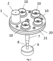
- Fig. 1 shows, in a perspective view, a hanger (1) along with a piece (2) placed on one of the workpiece grips (10).
- Each placed piece (2) is subject to lacquering or metallization process.
- the most preferable number is five for the workpiece grips (10), which number has been selected based on the size of the piece (2).
- the hanger (1) is constructed of a driving shaft (8) along with a central wheel sleeve (7) positioned thereon, a housing (23) and a driving element (9).
- the upper portion (8a) of the driving shaft (8) is immovably secured to the housing (23).
- the driving shaft (8) is welded with the sleeve (22) so that the flange (22a) of the sleeve (22) abuts the upper portion (7a) of the central wheel sleeve (7).
- the housing (23) in an embodiment is constructed of an upper portion (20) of the housing and a lower portion (21) of the housing.
- the upper portion (20) of the housing as seen in Fig. 2 , abuts the welded sleeve (22) and is pressed by a screw connection effected by means of a washer (16) and a screw (17), the connection being threaded.
- the central wheel (6) is seated immovably on the upper portion (7a) of the central wheel sleeve (7).
- Mounting of a workpiece grip (10) is effected by securing immovably a satellite gear gear (3) on a mounting roll (4) of the satellite gear wheel, bearing-seated, in the embodiment according to Fig. 2 , in the housing (23) at two ends via Teflon mounting roll sleeves (5).
- the piece grip is connected, by a screw (threaded) connection embodied by means of a screw (12), to the mounting roll (4) of the satellite gear wheel.
- a shielding washer (11) is arranged between a workpiece grip (10) and the mounting roll (4) of the satellite gear wheel.
- the central wheel (6) interact with satellite gear wheels (3).
- the presented embodiment in Fig. 3 shows a satellite gear wheel (3) of a smaller diameter than the central wheel (6).
- the transmission ratio used therein causes that the satellite gear wheels (3) make more revolutions than the central wheel (6).
- construction of a workpiece grip (10) is made compatible with size of the piece (2).
- the grip is constructed of a non-through hollow cylinder which in its bottom portion has a base of a smaller diameter and the cylinder in its bottom has a flange which acts as a base for the piece (2).
- a driving element which is connected to an external mechanism.
- the driving element is a driving disc (9) connected to a belt transmission.
- the driving disc (9) is mounted in the bottom portion (8b) of the driving shaft (8).
- This connection in the embodiment seen in Fig. 2 comprises a releasably threaded connection, by means of a washer (18) and a nut (19).
- several hangers (1) are mounted on a carrier element (24) being a carrier rail.
- the earlier type of the hanger along with the carrier element (24) is presented in Fig. 5 .
- the object of the invention is characterized by its flexibility and it may be used in an existing production line, without any need for modification of other elements.
- the operation mode of the hanger (1) for lacquering or metallization is as follows.
- the driving shaft (9) causes rotation of the housing (23) and thus movement of the satellite gear wheels (3) around their axes.
- the satellite gear wheels (3) cooperating with the central wheel (6) are moving on around the immovable central wheel (6) and cause rotation of the mounting rolls (4) of the satellite gear wheels around their axes along with the workpiece grips (10).
Landscapes
- Chemical & Material Sciences (AREA)
- Engineering & Computer Science (AREA)
- Chemical Kinetics & Catalysis (AREA)
- Electrochemistry (AREA)
- Materials Engineering (AREA)
- Metallurgy (AREA)
- Organic Chemistry (AREA)
- Coating Apparatus (AREA)
Claims (15)
- Ein Aufhänger, bestehend aus:einem zentralen Rad (6),mindestens einem Satellitenzahnrad (3),mindestens einem Werkstückgreifer (10),einem Gehäuse (23),wobei das zentrale Rad (6) unbeweglich auf einem oberen Ende (7a) einer zentralenRadhülse (7) sitzt, wobei die zentrale Radhülse (7) in einem unteren Abschnitt (7b) an einem Trägerelement (24) befestigt ist, und eine Antriebswelle (8) in der zentralen Radhülse (7) untergebracht ist, und die Antriebswelle (8) in einem unteren Abschnitt (8b) mit einem Antriebselement verbunden ist und ein oberer Abschnitt (8a) der Antriebswelle (8) unbeweglich an dem Gehäuse (23) befestigt ist;wobei jeder der mindestens einen Werkstückgreifer (10) relativ zu einer im Gehäuse (12) auf Lagern platzierten Befestigungsrolle (4) des Satellitenzahnrads befestigt ist;wobei jedes Satellitenzahnrad (3) unbeweglich an einer anderen Befestigungsrolle (4) des Satellitenzahnrads befestigt ist und jedes Satellitenzahnrad (3) mit dem zentralen Rad (6) zusammenwirkt.
- Aufhänger nach Anspruch 1, dadurch gekennzeichnet, dass das Antriebselement eine Antriebsscheibe (9) ist.
- Aufhänger nach Anspruch 2, dadurch gekennzeichnet, dass die Antriebsscheibe (9) mit einem Riemengetriebe verbunden ist.
- Aufhänger nach Anspruch 1, dadurch gekennzeichnet, dass das Gehäuse (23) einen oberen Teil (20) des Gehäuses und einen unteren Teil (21) des Gehäuses umfasst, die miteinander verbunden sind.
- Aufhänger nach den Ansprüchen 1 und 4, dadurch gekennzeichnet, dass zwischen dem oberen Teil (20) des Gehäuses und dem unteren Teil (21) des Gehäuses ein Abstandshalter (13) vorhanden ist.
- Aufhänger nach Anspruch 5, dadurch gekennzeichnet, dass durch den Abstandshalter (13) die Verbindung zwischen dem oberen Teil (20) des Gehäuses und dem unteren Teil (21) des Gehäuses verläuft.
- Aufhänger nach Anspruch 4 und 6, dadurch gekennzeichnet, dass die Verbindung des oberen Teils (20) des Gehäuses und des unteren Teils (21) des Gehäuses (21) eine lösbare Verbindung, vorzugsweise eine Schraubverbindung, aufweist.
- Aufhänger nach Anspruch 1, dadurch gekennzeichnet, dass das Satellitenzahnrad (3) einen kleineren Durchmesser hat als das zentrale Rad (6).
- Aufhänger nach Anspruch 4, dadurch gekennzeichnet, dass die Verbindung des oberen Teils (20) des Gehäuses mit der Antriebswelle (8) eine lösbare Verbindung, vorzugsweise eine Schraubverbindung, aufweist.
- Aufhänger (1) nach Anspruch 1, dadurch gekennzeichnet, dass die Anzahl der Satellitenzahnräder (3) weniger als fünf beträgt und vorzugsweise fünf beträgt.
- Aufhänger nach Anspruch 1, dadurch gekennzeichnet, dass sich zwischen dem Gehäuse (23) und der Antriebswelle (8) eine Hülse (22) mit einem Flansch (22a) befindet, wobei die Hülse (22) unbeweglich an der Antriebswelle (8) befestigt ist und die Hülse (22) vorzugsweise mit der Antriebswelle (8) verschweißt ist.
- Aufhänger nach Anspruch 1, dadurch gekennzeichnet, dass die Befestigungsrolle (4) des Satellitenzahnrades über eine Befestigungsrollenhülse (5) im Gehäuse (23) mit einem Lager platziert ist, und vorzugsweise mindestens eine Befestigungsrollenhülse (5) aus Teflon besteht.
- Aufhänger nach Anspruch 1, dadurch gekennzeichnet, dass das Trägerelement (24) eine Trägerschiene ist.
- Aufhänger nach Anspruch 1, dadurch gekennzeichnet, dass der untere Teil (8b) der Antriebswelle (8) lösbar mit dem Antriebselement verbunden ist.
- Aufhänger nach Anspruch 1, dadurch gekennzeichnet, dass der Griff (10) die Form eines nicht durchgehenden Hohlzylinders hat, der in seinem unteren Teil einen kleineren Durchmesser aufweist, und der Zylinder in seinem unteren Teil oberhalb eines kleineren Durchmessers einen Flansch aufweist, und am Boden des Hohlraums ein Durchgangsloch vorhanden ist, und der Griff (10) mit einer Befestigungsrolle (4) des Satellitenzahnrads durch eine durch das Durchgangsloch gehende Griffschraube (12) verbunden ist.
Priority Applications (2)
| Application Number | Priority Date | Filing Date | Title |
|---|---|---|---|
| EP21461635.1A EP4086010B1 (de) | 2021-12-14 | 2021-12-14 | Hänger |
| PL21461635.1T PL4086010T3 (pl) | 2021-12-14 | 2021-12-14 | Zawieszka |
Applications Claiming Priority (1)
| Application Number | Priority Date | Filing Date | Title |
|---|---|---|---|
| EP21461635.1A EP4086010B1 (de) | 2021-12-14 | 2021-12-14 | Hänger |
Publications (3)
| Publication Number | Publication Date |
|---|---|
| EP4086010A1 EP4086010A1 (de) | 2022-11-09 |
| EP4086010C0 EP4086010C0 (de) | 2024-05-15 |
| EP4086010B1 true EP4086010B1 (de) | 2024-05-15 |
Family
ID=80225729
Family Applications (1)
| Application Number | Title | Priority Date | Filing Date |
|---|---|---|---|
| EP21461635.1A Active EP4086010B1 (de) | 2021-12-14 | 2021-12-14 | Hänger |
Country Status (2)
| Country | Link |
|---|---|
| EP (1) | EP4086010B1 (de) |
| PL (1) | PL4086010T3 (de) |
Families Citing this family (2)
| Publication number | Priority date | Publication date | Assignee | Title |
|---|---|---|---|---|
| CN118461083B (zh) * | 2024-07-09 | 2024-10-22 | 沈阳仪表科学研究院有限公司 | 一种波纹管的电铸装置 |
| CN118808018B (zh) * | 2024-09-13 | 2024-12-20 | 芜湖舍达科技有限公司 | 一种多工位喷涂装置 |
Family Cites Families (5)
| Publication number | Priority date | Publication date | Assignee | Title |
|---|---|---|---|---|
| JPS58135473U (ja) * | 1982-03-04 | 1983-09-12 | コニカ株式会社 | 電解処理装置 |
| DE102010047496B4 (de) | 2010-10-06 | 2014-04-03 | Von Ardenne Gmbh | Drehtellervorrichtung für Prozesskammer |
| US20120321788A1 (en) | 2011-06-16 | 2012-12-20 | Pinecone Material Inc. | Rotation system for thin film formation |
| TWI564421B (zh) | 2015-08-25 | 2017-01-01 | 7-Leaders Corp | Material coating coating equipment folder fixture rotation mechanism |
| CN108588806B (zh) * | 2018-06-26 | 2023-07-07 | 广东保盈环保电镀设备有限公司 | 一种旋转电镀挂具 |
-
2021
- 2021-12-14 EP EP21461635.1A patent/EP4086010B1/de active Active
- 2021-12-14 PL PL21461635.1T patent/PL4086010T3/pl unknown
Also Published As
| Publication number | Publication date |
|---|---|
| PL4086010T3 (pl) | 2024-07-08 |
| EP4086010C0 (de) | 2024-05-15 |
| EP4086010A1 (de) | 2022-11-09 |
Similar Documents
| Publication | Publication Date | Title |
|---|---|---|
| EP4086010B1 (de) | Hänger | |
| EP1412279B1 (de) | Etikettiermaschine | |
| EP3178970B1 (de) | Gestell zur aufnahme von ringförmigen bauteilen sowie verfahren | |
| EP2387534B1 (de) | Behälterbehandlungsmaschine | |
| US4827836A (en) | Fruit and vegetable peeler | |
| CN112774917A (zh) | 一种内孔产品的自动化喷涂设备 | |
| DE102014218361A1 (de) | Vorrichtung und Verfahren zum Behandeln von Behältern durch Direktdruck und/oderEtikettierung | |
| CN112642615A (zh) | 一种用于热喷涂的四工位工作转台 | |
| CN206535696U (zh) | 一种上漆均匀的滚涂机 | |
| CN118287298B (zh) | 一种强耐腐蚀性的不锈钢表面加工工艺及加工装置 | |
| CN210366341U (zh) | 一种往复移动的收卷装置 | |
| CN219765753U (zh) | 一种喷涂工装机构及喷涂装置 | |
| CN110760810A (zh) | 转架及具有其的镀膜设备 | |
| DE1965549C3 (de) | Vorrichtung zum Ausrichten von mit Vertiefungen versehenen Früchten | |
| CN221663011U (zh) | 一种发饰真空镀膜用挂料回转机构 | |
| JP2877217B2 (ja) | 表面処理装置 | |
| JP3140693B2 (ja) | 円筒状物品の移送装置 | |
| DE3933911A1 (de) | Substrathalterung mit planetenbewegung | |
| CA1286187C (en) | Fruit and vegetable peeler | |
| CN112195450B (zh) | 一种车轮毂镀膜设备 | |
| CN117139553B (zh) | 一种冷镦机的送料装置 | |
| CN216838239U (zh) | 金属制品的表面处理装置 | |
| DE479459C (de) | Schleifen von Rollen in einem zwischen zwei ebenen Werkzeugen kreisenden Kaefig | |
| DE494767C (de) | Maschine zum Anbringen eines UEberzuges aus Firnis, Lack o. dgl. auf zylinderfoermigen Blechbuechsen | |
| CN222935482U (zh) | 一种用于类金刚石镀覆的试片涂镀装置 |
Legal Events
| Date | Code | Title | Description |
|---|---|---|---|
| PUAI | Public reference made under article 153(3) epc to a published international application that has entered the european phase |
Free format text: ORIGINAL CODE: 0009012 |
|
| STAA | Information on the status of an ep patent application or granted ep patent |
Free format text: STATUS: THE APPLICATION HAS BEEN PUBLISHED |
|
| AK | Designated contracting states |
Kind code of ref document: A1 Designated state(s): AL AT BE BG CH CY CZ DE DK EE ES FI FR GB GR HR HU IE IS IT LI LT LU LV MC MK MT NL NO PL PT RO RS SE SI SK SM TR |
|
| STAA | Information on the status of an ep patent application or granted ep patent |
Free format text: STATUS: REQUEST FOR EXAMINATION WAS MADE |
|
| 17P | Request for examination filed |
Effective date: 20230428 |
|
| RBV | Designated contracting states (corrected) |
Designated state(s): AL AT BE BG CH CY CZ DE DK EE ES FI FR GB GR HR HU IE IS IT LI LT LU LV MC MK MT NL NO PL PT RO RS SE SI SK SM TR |
|
| REG | Reference to a national code |
Ref country code: DE Ref legal event code: R079 Free format text: PREVIOUS MAIN CLASS: B05C0013000000 Ipc: B05B0013020000 Ref country code: DE Ref legal event code: R079 Ref document number: 602021013311 Country of ref document: DE Free format text: PREVIOUS MAIN CLASS: B05C0013000000 Ipc: B05B0013020000 |
|
| GRAP | Despatch of communication of intention to grant a patent |
Free format text: ORIGINAL CODE: EPIDOSNIGR1 |
|
| STAA | Information on the status of an ep patent application or granted ep patent |
Free format text: STATUS: GRANT OF PATENT IS INTENDED |
|
| RIC1 | Information provided on ipc code assigned before grant |
Ipc: B05C 13/02 20060101ALI20240215BHEP Ipc: C25D 17/08 20060101ALI20240215BHEP Ipc: C25D 17/06 20060101ALI20240215BHEP Ipc: B23Q 7/02 20060101ALI20240215BHEP Ipc: B05C 13/00 20060101ALI20240215BHEP Ipc: B05B 13/02 20060101AFI20240215BHEP |
|
| GRAS | Grant fee paid |
Free format text: ORIGINAL CODE: EPIDOSNIGR3 |
|
| INTG | Intention to grant announced |
Effective date: 20240304 |
|
| GRAA | (expected) grant |
Free format text: ORIGINAL CODE: 0009210 |
|
| STAA | Information on the status of an ep patent application or granted ep patent |
Free format text: STATUS: THE PATENT HAS BEEN GRANTED |
|
| AK | Designated contracting states |
Kind code of ref document: B1 Designated state(s): AL AT BE BG CH CY CZ DE DK EE ES FI FR GB GR HR HU IE IS IT LI LT LU LV MC MK MT NL NO PL PT RO RS SE SI SK SM TR |
|
| REG | Reference to a national code |
Ref country code: CH Ref legal event code: EP |
|
| REG | Reference to a national code |
Ref country code: IE Ref legal event code: FG4D |
|
| REG | Reference to a national code |
Ref country code: DE Ref legal event code: R096 Ref document number: 602021013311 Country of ref document: DE |
|
| U01 | Request for unitary effect filed |
Effective date: 20240605 |
|
| U07 | Unitary effect registered |
Designated state(s): AT BE BG DE DK EE FI FR IT LT LU LV MT NL PT SE SI Effective date: 20240620 |
|
| PG25 | Lapsed in a contracting state [announced via postgrant information from national office to epo] |
Ref country code: IS Free format text: LAPSE BECAUSE OF FAILURE TO SUBMIT A TRANSLATION OF THE DESCRIPTION OR TO PAY THE FEE WITHIN THE PRESCRIBED TIME-LIMIT Effective date: 20240915 |
|
| PG25 | Lapsed in a contracting state [announced via postgrant information from national office to epo] |
Ref country code: HR Free format text: LAPSE BECAUSE OF FAILURE TO SUBMIT A TRANSLATION OF THE DESCRIPTION OR TO PAY THE FEE WITHIN THE PRESCRIBED TIME-LIMIT Effective date: 20240515 |
|
| PG25 | Lapsed in a contracting state [announced via postgrant information from national office to epo] |
Ref country code: GR Free format text: LAPSE BECAUSE OF FAILURE TO SUBMIT A TRANSLATION OF THE DESCRIPTION OR TO PAY THE FEE WITHIN THE PRESCRIBED TIME-LIMIT Effective date: 20240816 |
|
| PG25 | Lapsed in a contracting state [announced via postgrant information from national office to epo] |
Ref country code: ES Free format text: LAPSE BECAUSE OF FAILURE TO SUBMIT A TRANSLATION OF THE DESCRIPTION OR TO PAY THE FEE WITHIN THE PRESCRIBED TIME-LIMIT Effective date: 20240515 |
|
| PG25 | Lapsed in a contracting state [announced via postgrant information from national office to epo] |
Ref country code: NO Free format text: LAPSE BECAUSE OF FAILURE TO SUBMIT A TRANSLATION OF THE DESCRIPTION OR TO PAY THE FEE WITHIN THE PRESCRIBED TIME-LIMIT Effective date: 20240815 Ref country code: IS Free format text: LAPSE BECAUSE OF FAILURE TO SUBMIT A TRANSLATION OF THE DESCRIPTION OR TO PAY THE FEE WITHIN THE PRESCRIBED TIME-LIMIT Effective date: 20240915 Ref country code: HR Free format text: LAPSE BECAUSE OF FAILURE TO SUBMIT A TRANSLATION OF THE DESCRIPTION OR TO PAY THE FEE WITHIN THE PRESCRIBED TIME-LIMIT Effective date: 20240515 Ref country code: GR Free format text: LAPSE BECAUSE OF FAILURE TO SUBMIT A TRANSLATION OF THE DESCRIPTION OR TO PAY THE FEE WITHIN THE PRESCRIBED TIME-LIMIT Effective date: 20240816 Ref country code: ES Free format text: LAPSE BECAUSE OF FAILURE TO SUBMIT A TRANSLATION OF THE DESCRIPTION OR TO PAY THE FEE WITHIN THE PRESCRIBED TIME-LIMIT Effective date: 20240515 Ref country code: RS Free format text: LAPSE BECAUSE OF FAILURE TO SUBMIT A TRANSLATION OF THE DESCRIPTION OR TO PAY THE FEE WITHIN THE PRESCRIBED TIME-LIMIT Effective date: 20240815 |
|
| U20 | Renewal fee for the european patent with unitary effect paid |
Year of fee payment: 4 Effective date: 20241120 |
|
| PGFP | Annual fee paid to national office [announced via postgrant information from national office to epo] |
Ref country code: PL Payment date: 20241114 Year of fee payment: 4 |
|
| PG25 | Lapsed in a contracting state [announced via postgrant information from national office to epo] |
Ref country code: CZ Free format text: LAPSE BECAUSE OF FAILURE TO SUBMIT A TRANSLATION OF THE DESCRIPTION OR TO PAY THE FEE WITHIN THE PRESCRIBED TIME-LIMIT Effective date: 20240515 |
|
| PG25 | Lapsed in a contracting state [announced via postgrant information from national office to epo] |
Ref country code: RO Free format text: LAPSE BECAUSE OF FAILURE TO SUBMIT A TRANSLATION OF THE DESCRIPTION OR TO PAY THE FEE WITHIN THE PRESCRIBED TIME-LIMIT Effective date: 20240515 Ref country code: SK Free format text: LAPSE BECAUSE OF FAILURE TO SUBMIT A TRANSLATION OF THE DESCRIPTION OR TO PAY THE FEE WITHIN THE PRESCRIBED TIME-LIMIT Effective date: 20240515 |
|
| PG25 | Lapsed in a contracting state [announced via postgrant information from national office to epo] |
Ref country code: SM Free format text: LAPSE BECAUSE OF FAILURE TO SUBMIT A TRANSLATION OF THE DESCRIPTION OR TO PAY THE FEE WITHIN THE PRESCRIBED TIME-LIMIT Effective date: 20240515 |
|
| PG25 | Lapsed in a contracting state [announced via postgrant information from national office to epo] |
Ref country code: SM Free format text: LAPSE BECAUSE OF FAILURE TO SUBMIT A TRANSLATION OF THE DESCRIPTION OR TO PAY THE FEE WITHIN THE PRESCRIBED TIME-LIMIT Effective date: 20240515 Ref country code: SK Free format text: LAPSE BECAUSE OF FAILURE TO SUBMIT A TRANSLATION OF THE DESCRIPTION OR TO PAY THE FEE WITHIN THE PRESCRIBED TIME-LIMIT Effective date: 20240515 Ref country code: RO Free format text: LAPSE BECAUSE OF FAILURE TO SUBMIT A TRANSLATION OF THE DESCRIPTION OR TO PAY THE FEE WITHIN THE PRESCRIBED TIME-LIMIT Effective date: 20240515 Ref country code: CZ Free format text: LAPSE BECAUSE OF FAILURE TO SUBMIT A TRANSLATION OF THE DESCRIPTION OR TO PAY THE FEE WITHIN THE PRESCRIBED TIME-LIMIT Effective date: 20240515 |
|
| REG | Reference to a national code |
Ref country code: DE Ref legal event code: R097 Ref document number: 602021013311 Country of ref document: DE |
|
| PLBE | No opposition filed within time limit |
Free format text: ORIGINAL CODE: 0009261 |
|
| STAA | Information on the status of an ep patent application or granted ep patent |
Free format text: STATUS: NO OPPOSITION FILED WITHIN TIME LIMIT |
|
| 26N | No opposition filed |
Effective date: 20250218 |
|
| PG25 | Lapsed in a contracting state [announced via postgrant information from national office to epo] |
Ref country code: MC Free format text: LAPSE BECAUSE OF FAILURE TO SUBMIT A TRANSLATION OF THE DESCRIPTION OR TO PAY THE FEE WITHIN THE PRESCRIBED TIME-LIMIT Effective date: 20240515 |
|
| REG | Reference to a national code |
Ref country code: CH Ref legal event code: PL |
|
| PG25 | Lapsed in a contracting state [announced via postgrant information from national office to epo] |
Ref country code: CH Free format text: LAPSE BECAUSE OF NON-PAYMENT OF DUE FEES Effective date: 20241231 |
|
| PG25 | Lapsed in a contracting state [announced via postgrant information from national office to epo] |
Ref country code: IE Free format text: LAPSE BECAUSE OF NON-PAYMENT OF DUE FEES Effective date: 20241214 |