EP4085759B1 - Materialschubvorrichtung und ladeverfahren dafür, und materialschubmaschine und materialschubverfahren dafür - Google Patents
Materialschubvorrichtung und ladeverfahren dafür, und materialschubmaschine und materialschubverfahren dafür Download PDFInfo
- Publication number
- EP4085759B1 EP4085759B1 EP20910355.5A EP20910355A EP4085759B1 EP 4085759 B1 EP4085759 B1 EP 4085759B1 EP 20910355 A EP20910355 A EP 20910355A EP 4085759 B1 EP4085759 B1 EP 4085759B1
- Authority
- EP
- European Patent Office
- Prior art keywords
- material pushing
- charging
- assembly
- annular wall
- wall body
- Prior art date
- Legal status (The legal status is an assumption and is not a legal conclusion. Google has not performed a legal analysis and makes no representation as to the accuracy of the status listed.)
- Active
Links
Images


Classifications
-
- A—HUMAN NECESSITIES
- A01—AGRICULTURE; FORESTRY; ANIMAL HUSBANDRY; HUNTING; TRAPPING; FISHING
- A01K—ANIMAL HUSBANDRY; AVICULTURE; APICULTURE; PISCICULTURE; FISHING; REARING OR BREEDING ANIMALS, NOT OTHERWISE PROVIDED FOR; NEW BREEDS OF ANIMALS
- A01K5/00—Feeding devices for stock or game ; Feeding wagons; Feeding stacks
- A01K5/02—Automatic devices
- A01K5/0266—Automatic devices with stable trolleys, e.g. suspended
-
- A—HUMAN NECESSITIES
- A01—AGRICULTURE; FORESTRY; ANIMAL HUSBANDRY; HUNTING; TRAPPING; FISHING
- A01K—ANIMAL HUSBANDRY; AVICULTURE; APICULTURE; PISCICULTURE; FISHING; REARING OR BREEDING ANIMALS, NOT OTHERWISE PROVIDED FOR; NEW BREEDS OF ANIMALS
- A01K5/00—Feeding devices for stock or game ; Feeding wagons; Feeding stacks
- A01K5/02—Automatic devices
-
- A—HUMAN NECESSITIES
- A01—AGRICULTURE; FORESTRY; ANIMAL HUSBANDRY; HUNTING; TRAPPING; FISHING
- A01K—ANIMAL HUSBANDRY; AVICULTURE; APICULTURE; PISCICULTURE; FISHING; REARING OR BREEDING ANIMALS, NOT OTHERWISE PROVIDED FOR; NEW BREEDS OF ANIMALS
- A01K1/00—Housing animals; Equipment therefor
- A01K1/10—Feed racks
- A01K1/105—Movable feed barriers
-
- G—PHYSICS
- G05—CONTROLLING; REGULATING
- G05D—SYSTEMS FOR CONTROLLING OR REGULATING NON-ELECTRIC VARIABLES
- G05D1/00—Control of position, course, altitude or attitude of land, water, air or space vehicles, e.g. using automatic pilots
- G05D1/02—Control of position or course in two dimensions
- G05D1/021—Control of position or course in two dimensions specially adapted to land vehicles
- G05D1/0259—Control of position or course in two dimensions specially adapted to land vehicles using magnetic or electromagnetic means
- G05D1/0261—Control of position or course in two dimensions specially adapted to land vehicles using magnetic or electromagnetic means using magnetic plots
-
- G—PHYSICS
- G05—CONTROLLING; REGULATING
- G05D—SYSTEMS FOR CONTROLLING OR REGULATING NON-ELECTRIC VARIABLES
- G05D1/00—Control of position, course, altitude or attitude of land, water, air or space vehicles, e.g. using automatic pilots
- G05D1/20—Control system inputs
- G05D1/24—Arrangements for determining position or orientation
- G05D1/243—Means capturing signals occurring naturally from the environment, e.g. ambient optical, acoustic, gravitational or magnetic signals
Definitions
- the present disclosure relates to a material pushing machinery, in particular to a material pushing apparatus and a charging method thereof, and a material pushing machine and a material pushing method.
- cow aquaculture models with matched scales and specializations become available.
- cows are kept in fold yards, and when the cows are to be fed, forage or other food is dropped outside the fold yards so the food doesn't get soiled with excreta on the ground.
- Cows eat by poking their heads through bars.
- the forage may be pushed further from the fold yards by the action of the cows eating, and may be pushed beyond the reach of the cows.
- the forage needs to be pushed back towards the fold yard many times during the feed.
- CN108207693A discloses a repelling robot for feeding in intelligent pasture.
- the repelling robot comprises a walking device, a rotary casing and a repelling device, wherein the rotary casing is mounted on the walking device and is driven to rotate by a driving device I, a top cover driven to rotate by the driving device I is arranged at the top of the rotary casing and is provided with a livestock detection device, the repelling device is in electric connection with the livestock detection device, and the walking device, the driving device I, the livestock detection device and the repelling device are in electric connection with a master controller.
- the robot rotates to push a forage heap during walking, can meet work requirements of most pastures, effectively solves problems of high labor cost, delay in feeding cattle and the like, and improves production benefit of the pasture. Besides, grazing can be achieved through a mechanical arm mounted at the top end of the robot, and accordingly labor intensity is lowered.
- CN105145387A discloses a forage grass pushing device, and belongs to the field of husbandry tools.
- the forage grass pushing device is applied to a feeding farm to feed livestock raised in rails.
- the forage grass pushing device comprises a cylindrical pushing fixing support, a rotary bearing, a plurality of rotary supports and a rotary pushing plate in a frustum shape.
- the pushing fixing support is vertically placed.
- the rotary bearing is arranged on the pushing fixing support.
- the rotary supports are connected with the rotary bearing and are all located above the rotary bearing, and the rotary bearing can drive the rotary supports to rotate with the pushing fixing support as a center.
- the inner wall of the rotary pushing plate is fixedly connected with the ends, away from the pushing fixing support, of the rotary supports.
- the forage grass pushing device can be fixed to a walking robot through the pushing fixing support, a driving gear is driven by a pushing driving motor, the rotary bearing is driven by the driving gear to rotate, the rotary bearing drives the rotary supports to rotate, the rotary pushing plate is driven by the rotary supports to rotate, forage grass is pushed to a feeding rail, the utilization rate of the forage grass is increased, and labor cost is reduced.
- CN107150330A discloses an intelligent mowing robot, and relates to the field of pasture mechanical equipment.
- a conical mowing plate is mounted under a rotary pushing plate;
- a collision-proof ring is arranged above the rotary pushing plate, and is connected with a speed reducer bracket through multiple insulation plates and connecting plates;
- a first charge electrode, an internal control unit, a two-dimensional electronic compass, a ultra-wide-band distance measurement positioning system and a ultrasonic sensor are arranged on the speed reducer bracket;
- an upper cover is arranged above the speed reducer bracket; and a charge pile is arranged on one side of the collision-proof ring.
- the intelligent mowing robot is controlled by a control unit to guarantee accurate driving along a feeding fence according to a preset path; and one rotatable surface at the lower part can push feeds to the feeding fence, and can push feed stacks with heights of 75 cm to realize automatic feeding of cows, so that the manual workload is reduced, and the continuous feeding effect of confined cows is improved.
- CN209073195U discloses the technical field of livestock breeding equipment, in particular to an intelligent pushing robot for a pasture.
- the utility model discloses an intelligent pushing robot for a pasture.
- a control device is arranged in the shell; the control device comprises a control unit and a storage battery; the control unit is in communication connection with the voice controller and the laser sensing processor, the storage battery is electrically connected with the servo motor and the control unit, the upper portion of the storage battery is connected with the connecting electrode, the servo motor is provided with a differential speed reduction system, driving wheels are arranged on the two sides of the control device, and universal wheels are arranged at the front end of the control device.
- the robot has the advantages that the self-adaptive sensor fusion technology is adopted, the robot does not depend on any environmental assistance, the automatic feeding function of the robot in the dairy farm is achieved, and the robot can be used in unmanned farms and indoors and outdoors and has high safety.
- US2019/129443A discloses an autonomous vehicle for pushing feed lying on a floor, comprising a frame; a skirt rotatably connected to the frame, wherein a bottom portion of the skirt continuously contacts the floor to push the feed.
- the vehicle comprises a sensor assembly for detecting a magnetic field emitted from a magnetic guiding element inserted in the floor and a control unit mounted for directing rotation of the skirt and for guiding the vehicle along a predetermined path formed by the magnetic guiding element.
- an autonomous vehicle with a skirt drive mechanism mounted to the frame for driving rotation of the skirt, and an autonomous vehicle comprising a prism-shaped skirt rotatably connected to the frame.
- CN106818507A discloses the technical field of agricultural machinery, in particular to a forage grass feeding device based on friction servo rotary.
- the forage grass feeding device comprises a shell body, a frame and push rod components; the cross section of the shell is circular, and the inner side of the shell is connected with the frame and the shell body can rotate around the frame; at least two of the push rod components are provided, and each push rod components is vertically arranged on a running mechanism, and the push rods of the push rod components are connected with the bottom of the frame; the tilting of the shell body is achieved by controlling each push rod components so that the shell body is in contact with the ground portion or the lifting of the shell body.
- the forage grass feeding device based on friction servo rotary adopts the friction force generated with the ground as the driving source, thereby saving cost and having simple structure; the bottom of the shell body does not contact with the ground in parallel, so the running resistance of the running gear is small.
- the present disclosure provides a material pushing apparatus and a charging method thereof, and a material pushing machine, and a material pushing method thereof.
- the material pushing apparatus provides a material pushing machine driven by electric energy, the material pushing machine may be automatically supplied with the electric energy, so as to improve an automation of the material pushing apparatus.
- the present disclosure provides a material pushing apparatus and a charging method thereof, and a material pushing machine and a material pushing method thereof.
- the material pushing apparatus provides a charger, the charger may automatically supply electric energy for the material pushing machine.
- the present disclosure provides a material pushing apparatus and a charging method thereof, and a material pushing machine and a material pushing method thereof.
- the material pushing machine may automatically move to and match the charger, the charger may automatically supply electric energy for the material pushing machine.
- the present disclosure provides a material pushing apparatus and a charging method thereof, and a material pushing machine and a material pushing method thereof.
- a charging assembly of the charger may be automatically connected to a charging port of the material pushing machine, so the material pushing machine may be automatically matched to the charger, the charger may automatically supply electric energy for the material pushing machine.
- the present disclosure provides a material pushing apparatus and a charging method thereof, and a material pushing machine and a material pushing method thereof.
- the charging assembly and the charging port may be automatically connected based on wireless charging principle, so the material pushing machine may be automatically matched to the charger, the charger may automatically supply electric energy for the material pushing machine.
- the charging assembly provides a first charging coil
- the charging port provides a second charging coil
- the second charging coil and the first charging coil are capable of automatically communicating, so the charger may automatically supply electric energy for the material pushing machine.
- the present disclosure provides a material pushing apparatus and a charging method thereof, and a material pushing machine and a material pushing method thereof.
- the material pushing machine is driven by electric energy, so it is silent in operation, and this and its small size should avoid the cows being frightened. Additionally, there is no pollution during the material pushing machine in operation, so as to ensure the health of the cows and quality of the milk.
- the present disclosure provides a material pushing apparatus and a charging method thereof, and a material pushing machine, and a material pushing method thereof.
- the material pushing machine may automatically push food such as forage towards a fold yard for providing accessible food for the cows in the fold yard.
- the present disclosure provides a material pushing apparatus and a charging method thereof, and a material pushing machine and a material pushing method thereof.
- the material pushing machine provides a walking device and a material pushing device arranged on the walking device, so that when the walking device walks along a path, the material pushing device rotates to push the forage in a certain direction, so the forage is pushed towards the fold yard.
- the present disclosure provides a material pushing apparatus and a charging method thereof, and a material pushing machine and a material pushing method thereof.
- An annular wall body of the material pushing device is capable of being rotated, so as to improve an efficiency of pushing the forage.
- the present disclosure provides a material pushing apparatus and a charging method thereof, and a material pushing machine and a material pushing method thereof.
- the material pushing device provides two pulley structures, the pulley structures may resist against a lower end of the annular wall body, so as to prevent shaking or waggling of the annular wall body, and prevent eccentricity and waggle of the material pushing machine, and ensuring the reliability and stability of the material pushing machine.
- the present disclosure provides a material pushing apparatus and a charging method thereof, and a material pushing machine and a material pushing method thereof.
- the material pushing device describes a circular orbit, the circular orbit is arranged on the annular wall body in a way of the circular orbit seats to an internal wall of the annular wall body, so the circular orbit may strengthen the annular wall body to prevent out of circularity of the annular wall body, when the annular wall body is drove to rotate related to the holding assembly, the pulley body of each pulley structure may roll on the smooth surface of the circular orbit, so as to reduce noise caused by mutual friction between the pulley structures and the circular orbit, thus the material pushing machine is more silence.
- a material pushing machine includes:
- a material pushing method of a material pushing machine includes:
- a material pushing apparatus includes:
- the charger includes a pair of charging electrodes
- the material pushing machine comprises a charging port
- the pair of charging electrodes are insertable into and becoming electrically connected to the charging port.
- a charging method of a material pushing apparatus includes:
- (b) further includes:
- first”, “second” and the like may be used herein to describe various directions, actions, steps or elements, but these directions, actions, steps or elements are not limited by these terms. These terms are used only to distinguish a first direction, action, step, or element from another direction, action, step, or element.
- the first module may be called the second module.
- the second module can be called the first module. Both the first module and the second module are modules, but they are not the same module.
- the terms “first”, “second”, etc. cannot be understood as indicating or implying relative importance or implicitly indicating the number of indicated technical features.
- the features defining “first” and “second” may explicitly or implicitly include one or more of the features.
- "a plurality of " means at least two, such as two, three, etc., unless otherwise specifically defined.
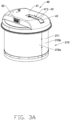
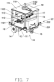
- FIGS. 1 to 8B illustrate a material pushing apparatus according to one embodiment of the present disclosure.
- the material pushing apparatus includes a material pushing machine 100 and a charger 200.
- the charger 200 may be electrically connected to a commercial power source and configured to automatically supply power for the material pushing machine 100. For instance, the charger 200 may adjust a voltage of the commercial power source for the material pushing machine 100, when the material pushing machine 100 approaches the charger 200, the material pushing machine 100 may automatically match the charger 200, thus the charger 200 may supply power for the material pushing machine 100.
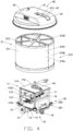
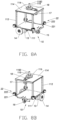
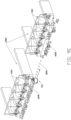
- the material pushing machine 100 includes a walking device 10 and a material pushing device 20 arranged on the walking device 10.
- the walking device 10 includes a holding assembly 11, a power supply assembly 12, two walking drive motors 13, two drive wheels 14, and a supporting wheel 15.
- the holding assembly 11 further includes a base plate 111, the power supply assembly 12 is arranged on and supported by the base plate 111, the charger 200 may automatically supply power for the power supply assembly 12.
- the two walking drive motors 13 are arranged on opposite ends of the base plate 111, each of the walking drive motors 13 is connected to the power supply assembly 12.
- the two drive wheels 14 are connected to the walking drive motors 13, the two drive wheels 14 are arranged on opposite ends of the base plate 111.
- the supporting wheel 15 is mounted in a middle of the base plate 111 on other side, thus the two drive wheels 14 and the supporting wheel 15 form a triangular structure, the two drive wheels 14 and the supporting wheel 15 cooperatively support the base plate 111 above the ground.
- the two drive wheels 14 are mounted on an output roller of the walking drive motors 13, thus the two drive wheels 14 may be connected to and driven by the walking drive motors 13.
- the supporting wheel 15 may be a universal wheel able to pivot through 360 degrees, for turning of the material pushing machine 100 in any direction.
- a shape of the base plate 111 is not limited, as shown in FIGS. 3A to 8B , the base plate 111 is substantially square, a center of gravity of the power supply assembly 12 coincides with a center of gravity of the base plate 111 in height, thus preventing any decline of a center of gravity of the material pushing machine 100, and ensuring a reliability and a stability of the material pushing machine 100.
- the base plate 111 may be, but is not limited to, circular, elliptic, and polygonal.
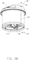
- the material pushing device 20 includes a material pushing wall 21, the material pushing wall 21 includes an annular wall body 211 and a connecting arm 212 extending from a top to a middle of the annular wall body 211.
- the connecting arm 212 is rotatably amounted on the holding assembly 11, the annular wall body 211 rotatably surrounds the holding assembly 11, thus the material pushing wall 21 forms the exterior of the material pushing machine 100.
- the material pushing machine 100 pushes the materials, forage or other food may not enter interior of the material pushing machine 100, and the walking device 10 will not be affected.
- the forage may be straw or a mixture of straw and fodder, the straw is substantially long and thin, the material pushing wall 21 is arranged on outside of the holding assembly 11 and forms the appearance of the material pushing machine 100, which may prevent the forage entering the internal of the material pushing machine 100 and affecting the walking device 10, so as to ensure a reliability and a stability of the material pushing machine 100.
- each of the walking drive motors 13 may convert electric energy into kinetic energy to drive each of the drive wheels 14 to run, thus, the walking device 10 may walk or at least follow a path.
- the walking device 10 is configured to walk straight along a path; when rotation speeds of the two walking drive motors 13 are different, the motion of the walking device 10 will be in a curve. For instance, when one of the walking drive motors 13 is rotating, and the other of the walking drive motors 13 is not working, the walking device 10 may make a sharp turn.
- a type of the power supply assembly 12 is not limited, such as the power supply assembly 12 may be a storage battery (such as but is not limited to lithium battery), when the electric energy stored in the power supply assembly 12 is consumed, the power supply assembly 12 will replenish electric energy.
- the power supply assembly 12 may include a storage battery (such as but is not limited to lithium battery), when the electric energy stored in the power supply assembly 12 is consumed, the power supply assembly 12 will replenish electric energy.
- the walking device 10 includes a controller 16, the power supply assembly 12 and each of the walking drive motors 13 are connected to the controller 16, the controller 16 controls power supply ways of the power supply assembly 12 to the walking drive motors 13.
- the controller 16 is arranged on and supported by the base plate 111.
- the controller 16 is arranged on the power supply assembly 12, or the controller 16 and the power supply assembly 12 are integrated.
- a type of the controller 16 is not limited, and may have a calculating function and a controlling function.
- the controller 16 may control a power from the power supply assembly 12 to each of the walking drive motors 13 according to a real-time status of the material pushing machine 100, so as to adjust a walking or path of movement of the material pushing machine 100.
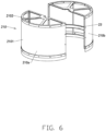
- the holding assembly 11 includes at least two support columns 112, a lower holding platform 113, and an upper holding platform 114.
- a lower end of each support column 112 is arranged on edges of the base plate 111 and extended from the edges of the base plate 111 to a predetermined height.
- a periphery of the lower holding platform 113 is arranged in a middle portion of each support column 112, so each support column 112 may support and maintain the lower holding platform 113 on the base plate 111, and a first receiving space 1101 of the holding assembly 11 is formed between the base plate 111 and the lower holding platform 113.
- a periphery of the upper holding platform 114 is arranged in an upper portion of each support column 112, so each support column 112 may support and maintain the upper holding platform 114 over the lower holding platform 113, and a second receiving space 1102 of the holding assembly 11 is formed between the lower holding platform 113 and the upper holding platform 114.
- the holding assembly 11 has the first receiving space 1101 and the second receiving space 1102.
- the first receiving space 1101 is formed between the base plate 111 and the lower holding platform 113, for receiving the power supply assembly 12 mounted on the base plate 111.
- the second receiving space 1102 is formed between the lower holding platform 113 and the upper holding platform 114, for receiving the controller 16 mounted on the lower holding platform 113.
- other electrical components such as but is not limited to fuse, power manager, communication module of the walking device 10 may also be received in the second receiving space 1102 and contained in the lower holding platform 113.
- the holding assembly 11 has only one holding platform, the holding platform is arranged on an upper end of each support column 112, a receiving space is formed between the base plate 111 and the holding platform, the power supply assembly 12 and the controller 16 arranged on the base plate 111 are received in the receiving space.
- the holding assembly 11 includes four support columns 112, a lower end of each support column 112 is arranged at a corner of the base plate 111.
- Each corner of the lower holding platform 113 is arranged at middle portion of each support column 112, so each support column 112 may maintain the lower holding platform 113 above the base plate 111, the first receiving space 1101 is formed between the base plate 111 and the lower holding platform 113.
- Each corner of the upper holding platform 114 is at upper portion of each support column 112, so each support column 112 holds the upper holding platform 114 above the lower holding platform 113, the second receiving space 1102 is formed between the lower holding platform 113 and the upper holding platform 114.
- the holding assembly 11 further includes a mounting column 115 and a drive ring 116.
- the mounting column 115 is arranged from a center position of the upper holding platform 114 extending upwardly to form a free end 1150.
- the drive ring 116 is rotatably mounted to a middle portion of the mounting column 115.
- a manner of the mounting column 115 being arranged on the upper holding platform 114 is not limited, for instance, the mounting column 115 and the upper holding platform 114 may be integrally formed, or the mounting column 115 is a screw joint to the upper holding platform 114, or the mounting column 115 is welded to the upper holding platform 114.
- a manner of the drive ring 116 being rotatably mounted to the mounting column 115 is not limited, for instance, the drive ring 116 is rotatably mounted to the mounting column 115 through a bearing.
- the walking device 10 further includes a material pushing drive motor 17.
- the material pushing drive motor 17 is arranged on the upper holding platform 114 and electrically connected to the power supply assembly 12, when the power supply assembly 12 supplies power to the material pushing drive motor 17, the material pushing drive motor 17 may convert electric energy into kinetic energy.
- the material pushing drive motor 17 is connected to the controller 16, so the controller 16 may control manner of supplying power to the material pushing drive motor 17.
- the drive ring 116 is drivable and connected to the material pushing drive motor 17.
- the connecting arm 212 of the material pushing wall 21 is extended to and fixedly amounted to the drive ring 116.
- the walking device 10 further includes a transmission belt 18. Opposite ends of the transmission belt 18 are mounted to an output roller of the material pushing drive motor 17 and the drive ring 116, so the drive ring 116 is drivable and connected to the material pushing drive motor 17.
- the output roller of the material pushing drive motor 17 includes a gear structure and the drive ring 116 includes a gear structure, so the gear structure of the drive ring 116 engages with the gear structure of the material pushing drive motor 17, thus the drive ring 116 is drivable and connected to the material pushing drive motor 17.
- the material pushing device 20 further includes at least two pulley structures 22.
- Each pulley structure 22 includes a mounting body 221 and a pulley body 222 rotatably mounted on the mounting body 221.
- the pulley structures 22 are maintained between the annular wall body 211 and the holding assembly 11, the pulley structures 22 are mounted to the holding assembly 11 through the mounting body 221 such that the pulley body 222 resists the annular wall body 211.
- each pulley structure 22 acts to prevent waggling and eccentric rotation of the annular wall body 211, so as to prevent eccentricity and waggle of the material pushing machine 100, and ensuring the reliability and stability of the material pushing machine 100.
- each pulley structure 22 is mounted to a lower end of each support column 112, so the pulley structures 22 resists the annular wall body 211 at the lower end of the annular wall body 211.
- each pulley structure 22 prevents waggles and eccentric rotation of the annular wall body 211.
- each pulley structure 22 is mounted to the base plate 111, so the pulley structures 22 may resist the annular wall body 211 at the lower end of the annular wall body 211.
- each pulley structure 22 may prevent waggles of the annular wall body 211.
- a quantity of the pulley structures 22 and a quantity of the support columns 112 is same, such as in the material pushing machine 100 as shown in FIGS. 3A to 8B , the quantity of the pulley structures 22 and the quantity of the support columns 112 are four, the lower end of each support column 112 carries one pulley structure 22.
- the material pushing device 20 further includes a circular orbit 23.
- the circular orbit 23 is arranged on the annular wall body 211 such that the circular orbit 23 seats to an internal wall of the annular wall body 211, so the circular orbit 23 may strengthen the annular wall body 211 to maintain a perfect roundness and circularity of the annular wall body 211.
- the pulley body 222 of each pulley structure 22 seats to a smooth surface of the circular orbit 23 to resist the annular wall body 211.
- each pulley structure 22 may roll on the smooth surface of the circular orbit 23, so as to reduce noise caused by friction between the pulley structures 22 and the circular orbit 23, thus the material pushing machine 100 is more silent.
- the material pushing wall 21 includes at least two roller half bodies 210.
- Each roller half body 210 includes a roller wall 2101 and an extending arm 2102 extended from an upper end of the roller wall 2101.
- the roller walls 2101 of adjacent roller half bodies 210 may be mounted to each other, after the roller half bodies 210 are mounted, the roller wall 2101 of each roller half body 210 forms the annular wall body 211, the extending arm 2102 of each roller half body 210 forms the connecting arm 212.
- the material pushing wall 21 includes two roller half bodies 210, one of the two roller half bodies 210 is defined as first roller half body 210a, the other of the two roller half bodies 210 is defined as second roller half body 210b.
- Each of the first roller half body 210a and the second roller half body 210b includes one roller wall 2101 and one extending arm 2102.
- the roller wall 2101 of the first roller half body 210a and the roller wall 2101 of the second roller half body 210b are mounted to each other to form the annular wall body 211, the extending arm 2102 of the first roller half body 210a and the extending arm 2102 of the second roller half body 210b form the connecting arm 212.
- the circular orbit 23 includes a first circular orbit 23a and a second circular orbit 23b.
- the first circular orbit 23a is arranged on the roller wall 2101 of the first roller half body 210a
- the second circular orbit 23b is arranged on the roller wall 2101 of the second roller half body 210b.
- the first circular orbit 23a and the second circular orbit 23b form a complete circular orbit 23.
- the material pushing machine 100 further includes a magnetic sensor 30.
- the magnetic sensor 30 is arranged on a lower portion of the base plate 111.
- the magnetic sensor 30 is capable of communicating with magnetic navigation markers lying outside the fold yard, for guiding the walking device 10 to move along a path.
- the material pushing machine 100 further includes a cover device 40.
- the cover device 40 includes a cover 41.
- a center position of the cover 41 is mounted to the free end 1150 of the mounting column 115, so the cover 41 may be supported by the holding assembly 11.
- a periphery of the cover 41 extends outwardly, thus a diameter of the cover 41 is greater than the periphery of the annular wall body 211, so the cover 41 protects and shields an upper portion of the annular wall body 211.
- the cover device 40 further includes a hold pole 42 and a distance sensor 43 arranged on an end of the hold pole 42.
- the other end of the hold pole 42 is arranged to the cover 41.
- the distance sensor 43 may obtain a distance between the material pushing machine 100 and the fold yard for adjusting the distance between the material pushing machine 100 and the fold yard when adjustment is required.
- the hold pole 42 is rotatably mounted to the cover 41 for adjusting an angle between the hold pole 42 and the cover 41. For instance, when the material pushing machine 100 is in operation, the hold pole 42 may rotate related to the cover 41, so the hold pole 42 and the cover 41 may have a greater angle, and so as to adjust the distance between the distance sensor 43 and the fold yard.
- the hold pole 42 is an expansion pole, that is, a length of the hold pole 42 may be adjusted, thus, through adjusting the length of the hold pole 42 and the angle between the hold pole 42 and the cover 41, the distance between the distance sensor 43 and the fold yard may be adjusted conveniently and flexibly.
- the cover 41 includes a maintain groove 411 for receiving the hold pole 42.
- the mounting column 115 is a cylindrical or hollow mounting column, that is, the mounting column 115 includes a connected channel (not shown in the figures) for connecting the second receiving space 1102 and the external space of the upper holding platform 114. Cables connected to the distance sensor 43 may be extended from the external space of the upper holding platform 114 to the second receiving space 1102 through the connected channel.
- the material pushing machine 100 further includes a charging port 50.
- the charging port 50 is arranged on the cover 51 and electrically connected to the power supply assembly 12, so the material pushing machine 100 may obtain electric energy from power supply assembly through the charging port 50.
- cables connected to the charging port 50 may be extended from the external space of the upper holding platform 114 to the first receiving space 1101 through the connected channel, and be connected to the power supply assembly 12.
- the charger 200 includes a charging adapter 60 and a charging assembly 70.
- the charging assembly 70 includes a connecting end 71, a charging end 72 corresponding to the connecting end 71, and a pair of charging electrodes 73 arranged on the charging end 72.
- the connecting end 71 is movably mounted on the charging adapter 60.
- the charging assembly 70 brings the charging end 72 closer to or away from the charging adapter 60.
- the connecting end 71 is drivable and mounted on the charging adapter 60, the charging adapter 60 may drive the charging assembly 70 bring the charging end 72 closer to or away from the charging adapter 60.
- the charging adapter 60 may internally include a drive motor and a mounting channel.
- the connecting end 71 may extend to an interior of the charging adapter 60 through the mounting channel and be drivable and mounted to the drive motor.
- the drive motor may drive the connecting end 71, thus relative positions of the charging assembly 70 and the charging adapter 60 may be changed, so the charging end 72 approaches or moves away from the charging adapter 60.
- the charging adapter 60 of the charger 200 may drive the charging assembly 70 to bring the charging end 72 closer to or away from the charging adapter 60, the charging end 72 may be inserted into the charging port 50, the charging electrodes 73 may electrically connect to the charging port 50, so the charging adapter 60 may supply electric energy to the power supply assembly 12. After the material pushing machine 100 is supplied with electric energy, the charging adapter 60 may drive the charging assembly 70 to move the charging end 72 away from the charging port 50 and closer to the charging adapter 60.
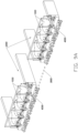
- FIGS. 9A to 9F illustrate an operation process of the material pushing machine 100.
- a number of cows 1000 are in a same fold yard 2000, there is at least one magnetic navigation path 3000 arranged between adjacent fold yards 2000, food 4000, such as forage, is arranged outside of the fold yard 2000 for consumption by the cows 1000 in the fold yard 2000.
- the cows 1000 in the fold yard 2000 may stretch out of the fold yard 2000 to eat the food 4000, the cows 1000 may, in act of eating, push the food 4000 away from the fold yard 2000, in such situation, the cows 1000 may not reach and eat all the food 4000.
- the material pushing machine 100 is used for pushing distant food 4000 towards the fold yard 2000, for being reached by the cows 1000 in the fold yard 2000.
- the annular wall body 211 of the material pushing device 20 may be rotated relative to the holding assembly 11, so the annular wall body 211 may push back the food 4000 closer towards the fold yard 2000, for being reached by the cows 1000 in the fold yard 2000.
- the distance sensor 43 may detect the distance between the material pushing machine 100 and the fold yard 2000 in real time, to ensure the food 4000 is correctly replaced closer to the fold yard 2000.
- the magnetic sensor 30 and the magnetic navigation path 3000 may cooperatively and correctly guide the material pushing machine 100 to move from one position of the fold yard 2000 to another position of the fold yard 2000.
- a material pushing method of the material pushing machine 100 includes the following:
- the path is predetermined, such as arranging magnetic guiding elements in advance outside the fold yard 2000 to form the magnetic navigation path 3000, so the magnetic navigation path 3000 may indicate the predetermined path.
- the distance sensor 43 detects the distance between the material pushing machine 100 and the fold yard 2000 in real time and plans and executes the path in real time.
- friction generated between the food 4000 and the annular wall body 211 may drive the annular wall body 211 to rotate related to the holding assembly 11, thus the annular wall body 211 surrounds the holding assembly 11 to push the food 4000.
- the material pushing drive motor 17 drives the annular wall body 211 to rotate relative to the holding assembly 11, so the annular wall body 211 surrounds the holding assembly 11 to push the food 4000.
- the material pushing drive motor 17 drives the annular wall body 211 to rotate related to the holding assembly 11 at the upper end of the annular wall body 211
- the at least two circular orbits 23 which are inside resist the annular wall body 211 at the internal of the annular wall body 211, so as to prevent eccentricity and waggling when the annular wall body 211 unilaterally suffers resistance from the mass of the food 4000, and ensuring the reliability and stability of the material pushing machine 100.
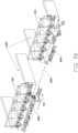
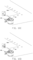
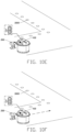
- FIGS. 10A to 10F illustrate a process of the charger 200 supplying power to the material pushing machine 100.
- the charger 200 is arranged close to a commercial power source, the charging adapter 60 is electrically connected to the commercial power source, the magnetic navigation path 3000 may extend outwardly from the charger 200 to guide the material pushing machine 100 to move closer to the charge 200 along the magnetic navigation path 3000.
- the material pushing machine 100 may move to the charger 200 along the magnetic navigation path 3000.
- the charging adapter 60 may drive the charging assembly 70 to bring the charging end 72 gradually closer to and be inserted in the charging port 50, then the charging electrodes 73 are electrically connected to the charging port 50, thus the charger 200 may supply power again to the power supply assembly 12.
- the charging adapter 60 may drive the charging assembly 70 to separate the charging end 72 from the charging port 50 and move close to charging adapter 60.
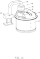
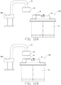
- FIGS. 11 to 12B illustrate a material pushing apparatus of another embodiment.
- the charging assembly 70 includes a supporting portion 74 and a first charging coil 75 arranged on the supporting portion 74.
- the supporting portion 74 is arranged on a top portion of the charging adapter 60 and extended outwardly from the top portion of the charging adapter 60.
- the first charging coil 75 is electrically connected to the charging adapter 60.
- the charging port 50 includes a second charging coil 51.
- the second charging coil 51 is arranged on the cover 41.
- the supporting portion 74 is arranged on a bottom portion of the charging adapter 60 and extended outwardly from the bottom portion of the charging adapter 60, the second charging coil 51 is arranged on the base plate 111.
- the second charging coil 51 and the first charging coil 75 automatically form the electromagnetic field, so the material pushing machine 100 may be automatically matched to the charger 200, thus the charger 200 may supply power to the material pushing machine 100.
- a charging method of the material pushing apparatus may include the following:
- process (b) further includes:
Landscapes
- Life Sciences & Earth Sciences (AREA)
- Environmental Sciences (AREA)
- Engineering & Computer Science (AREA)
- Physics & Mathematics (AREA)
- Biodiversity & Conservation Biology (AREA)
- General Physics & Mathematics (AREA)
- Automation & Control Theory (AREA)
- Radar, Positioning & Navigation (AREA)
- Animal Husbandry (AREA)
- Aviation & Aerospace Engineering (AREA)
- Remote Sensing (AREA)
- Electromagnetism (AREA)
- Birds (AREA)
- Zoology (AREA)
- Charge And Discharge Circuits For Batteries Or The Like (AREA)
- Catching Or Destruction (AREA)
Claims (16)
- Eine Materialschiebemaschine (100), umfassend:eine Gehvorrichtung (10), die eine Halteanordnung (11), eine Stromversorgungsanordnung (12), zwei Gehantriebsmotoren (13), zwei Antriebsräder (14) und ein Stützrad (15) umfasst, wobei die Halteanordnung (11) eine Grundplatte (111) umfasst, die Stromversorgungsanordnung (12) auf der Grundplatte (111) angeordnet ist, jeder der beiden Gehantriebsmotoren (13) auf einer gegenüberliegenden Seite eines Endes der Grundplatte (111) angeordnet und elektrisch mit der Stromversorgungsanordnung (12) verbunden ist, jedes der beiden Antriebsräder (14) antreibbar und mit einem entsprechenden der beiden Gehantriebsmotoren (13) verbunden ist und das Stützrad (15) in einer Mitte der Grundplatte (111) an einem anderen Ende angeordnet ist; undeine Materialschiebevorrichtung (20), die eine Materialschiebewand (21) umfasst, wobei die Materialschiebewand (21) einen ringförmigen Wandkörper (211) und einen Verbindungsarm (212) umfasst, der sich von einem oberen Ende des ringförmigen Wandkörpers (211) nach innen erstreckt, wobei der Verbindungsarm (212) mit der Halteanordnung (11) verbunden ist, wobei der ringförmige Wandkörper (211) die Halteanordnung (11) drehbar umgibt,dadurch gekennzeichnet, dassdie Materialschiebevorrichtung (20) weist mindestens zwei Riemenscheibenstrukturen (22) und eine Kreisbahn (23) auf, wobei die Kreisbahn (23) an einer Innenwand des ringförmigen Wandkörpers (211) anliegt, jede der mindestens zwei Riemenscheibenstrukturen (22) einen Montagekörper (221) und einen Riemenscheibenkörper (222) aufweist, der drehbar an dem Montagekörper (221) angebracht ist, wobei jede der mindestens zwei Riemenscheibenstrukturen (22) durch den Montagekörper (221) an der Halteanordnung (11) angebracht ist, wobei der Riemenscheibenkörper (222) nach außen an einer glatten Oberfläche der Kreisbahn (23) anliegt, um einer Innenseite des ringförmigen Wandkörpers (211) Widerstand zu leisten.
- Materialschiebemaschine (100) nach Anspruch 1, wobei die Halteanordnung (11) mindestens zwei Stützsäulen (112), eine Halteplattform (114), eine Montagesäule (115) und einen Antriebsring (116) umfasst; wobei jede der mindestens zwei Stützsäulen (112) von einer Kante der Grundplatte (111) bis zu einer vorgegebenen Höhe verlängert ist, die Halteplattform (114) an einem oberen Ende jeder der mindestens zwei Stützsäulen (112) angeordnet ist, ein Aufnahmeraum (1101, 1102) zwischen der Grundplatte (111) und der Halteplattform (114) zum Aufnehmen der Stromversorgungsanordnung (12) gebildet ist, die Montagesäule (115) von einer Mittelposition der Halteplattform (114) nach oben verlängert angeordnet ist, der Antriebsring (116) drehbar an der Montagesäule (115) montiert ist und der Verbindungsarm (212) mit dem Antriebsring (116) verbunden ist.
- Die Materialschiebemaschine (100) gemäß Anspruch 2, wobei die Gehvorrichtung (10) ferner einen Materialschieber -Antriebsmotor (17) umfasst, wobei der Materialschieber -Antriebsmotor (17) auf der Halteplattform (114) angeordnet und elektrisch mit der Stromversorgungsanordnung (12) verbunden ist, wobei der Antriebsring (116) antreibbar und mit dem Materialschieber - Antriebsmotor (17) verbunden ist;wobei die Gehvorrichtung (10) ferner einen Antriebsriemen (18) umfasst, wobei gegenüberliegende Enden des Antriebsriemens (18) an einer Ausgangsrolle des Materialschieber - Antriebsmotors (17)und dem Antriebsring (116) montiert sind, so dass der Antriebsring (116) antreibbar und mit dem Materialschieber - Antriebsmotor (17) verbunden ist.
- Die Materialschiebemaschine (100) gemäß einem der Ansprüche 1 bis 3, die ferner eine Abdeckvorrichtung (40) umfasst, wobei die Abdeckvorrichtung (40) eine Abdeckung (41) umfasst, wobei eine Mittelposition der Abdeckung (41) an einem freien Ende (1150) der Halteanordnung (11) montiert ist, ein Umfang der Abdeckung (41) sich nach außen erstreckt, ein Durchmesser der Abdeckung (41) größer ist als der Umfang des ringförmigen Wandkörpers (211);wobei die Abdeckvorrichtung (40) ferner eine Haltestange (42) und einen Abstandssensor (43) umfasst, der an einem Ende der Haltestange (42) angeordnet ist, wobei ein anderes Ende der Haltestange (42) an der Abdeckung (41) angeordnet ist;wobei die Abdeckung (41) eine Haltenut (411) zum Aufnehmen der Haltestange (42) und des Abstandssensors (43) umfasst; undwobei die Abdeckvorrichtung (40) einen Ladeanschluss (50) umfasst, wobei der Ladeanschluss (50) an der Abdeckung (41) angeordnet ist.
- Materialschiebemaschine (100) nach Anspruch 4, wobei die Montagesäule (115) einen verbundenen Kanal zum Verbinden des Aufnahmeraums (1101, 1102) und eines Außenraums der Halteplattform (114) umfasst, wobei Kabel, die mit dem Ladeanschluss (50) verbunden sind, durch den verbundenen Kanal zum Aufnahmeraum (1101, 1102) geführt sind.
- Verfahren zum Materialschieben der Materialschiebemaschine (100) nach einem der Ansprüche 1 bis 5, wobei das Verfahren zum Materialschieben die Schritte umfasst:(a) Konfigurieren einer Gehvorrichtung (10) zum Gehen entlang eines Pfads außerhalb eines Abstellplatzes; und(b) Konfigurieren eines ringförmigen Wandkörpers (211) einer Materialschiebewand (21) der Materialschiebemaschine (100), um relativ zu einer Halteanordnung (11) der Gehvorrichtung (10) in einer Weise rotiert zu werden, dass er die Halteanordnung (11) umgibt, so dass der ringförmige Wandkörper (211) Lebensmittel in einen vordefinierten Bereich des Abstellplatzes schiebt.
- Verfahren zum Materialschieben nach Anspruch 6, wobei Schritt (b) ferner umfasst: Antreiben des ringförmigen Wandkörpers (211) zum Rotieren relativ zur Halteanordnung (11) durch einen Materialschieber-Antriebsmotor (17).
- Verfahren zum Materialschieben nach Anspruch 7, wobei, wenn der Materialschieber-Antriebsmotor (17) den ringförmigen Wandkörper (211) antreibt, um ihn relativ zur Halteanordnung (11) an einem oberen Ende des ringförmigen Wandkörpers (211) zu drehen, mindestens zwei an der Halteanordnung (11) angeordnete Riemenscheibenstrukturen (22) an einer Innenseite des ringförmigen Wandkörpers (211) Widerstand leisten.
- Verfahren zum Materialschieben nach Anspruch 8, das ferner umfasst: Konfigurieren eines Rollenkörpers (222) jeder der mindestens zwei Rollenstrukturen (22), um relativ zu dem ringförmigen Wandkörper (211) entlang einer Kreisbahn (23) zu rotieren, die auf dem ringförmigen Wandkörper (211) angeordnet ist;
wobei eine Stromversorgungsanordnung (12) zwei Gehantriebsmotoren (13), die auf einer Grundplatte (111) der Halteanordnung (11) angeordnet sind, mit Strom versorgt, um es den beiden Gehantriebsmotoren (13) zu ermöglichen, ein Antriebsrad (14) der Gehvorrichtung (10) anzutreiben, um entlang des Pfads zu gehen. - Eine Materialschiebevorrichtung, umfassend:ein Ladegerät (200); unddie Materialschiebemaschine (100) gemäß einem der Ansprüche 1 bis 5, wobei, wenn die Materialschiebemaschine (100) sich zum Ladegerät (200) bewegt, das Ladegerät (200) die Materialschiebemaschine (100) automatisch mit Strom versorgt.
- Materialschiebevorrichtung nach Anspruch 10, wobei das Ladegerät (200) ein Paar Ladeelektroden (73) umfasst, wobei die Materialschiebemaschine (100) einen Ladeanschluss (50) umfasst, wobei das Paar Ladeelektroden (73) in den Ladeanschluss (50) eingesetzt und elektrisch mit diesem verbunden ist;wobei das Ladegerät (200) eine erste Ladespule (75) umfasst, wobei die Materialschiebemaschine (100) eine zweite Ladespule (51) umfasst und wobei die zweite Ladespule (51) und die erste Ladespule (75) in der Lage sind, automatisch miteinander zu kommunizieren;wobei das Ladegerät (200) einen Ladeadapter (60) und eine Ladebaugruppe (70) umfasst, wobei die Ladebaugruppe (70) ein Anschlussende (71), ein dem Anschlussende (71) entsprechendes Ladeende (72) und das am Ladeende (72) angeordnete Paar Ladeelektroden (73) umfasst, wobei das Ladeende (72) mit dem Ladeadapter (60) verbunden ist, undwobei das Paar Ladeelektroden (73) elektrisch mit dem Ladeadapter (60) verbunden ist; undwobei die Materialschiebemaschine (100) eine Gehvorrichtung (10), eine Materialschiebevorrichtung (20) und eine Abdeckvorrichtung (40) umfasst; wobei die Gehvorrichtung (10) eine Halteanordnung (11), eine Stromversorgungsanordnung (12), zwei Gehantriebsmotoren (13), zwei Antriebsräder (14) und ein Stützrad (15) umfasst, wobei die Halteanordnung (11) eine Grundplatte (111) umfasst, die Stromversorgungsanordnung (12) auf der Grundplatte (111) angeordnet ist, jeder der beiden Gehantriebsmotoren (13) auf gegenüberliegenden Seiten eines Endes der Grundplatte (111) angeordnet und elektrisch mit der Stromversorgungsanordnung (12) verbunden ist, jedes der beiden Antriebsräder (14) antreibbar und mit jedem der beiden Gehantriebsmotoren (13) verbunden ist und das Stützrad (15) in einer Mitte der Grundplatte (111) an einem anderen Ende angeordnet ist; wobei die Materialschiebevorrichtung (20) eine Materialschiebewand (21) umfasst, wobei die Materialschiebewand (21) einen ringförmigen Wandkörper (211) und einen Verbindungsarm (212) umfasst, der sich von einem oberen Ende des ringförmigen Wandkörpers (211) nach innen erstreckt, wobei der Verbindungsarm (212) mit der Halteanordnung (11) verbunden ist und wobei der ringförmige Wandkörper (211) die Halteanordnung (11) drehbar umgibt; und wobei die Abdeckvorrichtung (40) eine Abdeckung (41) umfasst, wobei die Abdeckung (41) auf der Halteanordnung (11) montiert ist, ein Umfang der Abdeckung (41) sich nach außen erstreckt und ein Durchmesser der Abdeckung (41) größer ist als der Umfang des ringförmigen Wandkörpers (211); und wobei der Ladeanschluss (50) auf der Abdeckung (41) angeordnet und elektrisch mit der Stromversorgungsanordnung (12) verbunden ist.
- Materialschiebevorrichtung nach Anspruch 11, wobei die Halteanordnung (11) mindestens zwei Stützsäulen (112), eine Halteplattform (114), eine Montagesäule (115) und einen Antriebsring (116) umfasst; wobei jede der mindestens zwei Stützsäulen (112) von einer Kante der Grundplatte (111) bis zu einer vorgegebenen Höhe verlängert ist, die Halteplattform (114) an einem oberen Ende jeder der mindestens zwei Stützsäulen (112) angeordnet ist, ein Aufnahmeraum (1101, 1102) zwischen der Grundplatte (111) und der Halteplattform (114) zum Aufnehmen der Stromversorgungsanordnung (12) gebildet ist, die Montagesäule (115) von einer Mittelposition der Halteplattform (114) nach oben verlängert angeordnet ist, der Antriebsring (116) drehbar an der Montagesäule (115) montiert ist und der Verbindungsarm (212) mit dem Antriebsring (116) verbunden ist;wobei die Gehvorrichtung (10) ferner einen Materialschieber - Antriebsmotor (17) umfasst, wobei der Materialschieber - Antriebsmotor (17) auf der Halteplattform (114) angeordnet und elektrisch mit der Stromversorgungsanordnung (12) verbunden ist, und der Antriebsring (116) antreibbar und mit dem Materialschieber - Antriebsmotor (17) verbunden ist;wobei die Materialschiebevorrichtung (20) ferner mindestens zwei Riemenscheibenstrukturen (22) umfasst, wobei jede der mindestens zwei Riemenscheibenstrukturen (22) einen Montagekörper (221) und einen Riemenscheibenkörper (222) umfasst, der drehbar auf dem Montagekörper (221) montiert ist, wobei der Riemenscheibenkörper (222) nach außen hin einem Inneren des ringförmigen Wandkörpers (211) Widerstand entgegensetzt, so dass jede der mindestens zwei Riemenscheibenstrukturen (22) an der Halteanordnung (11) montiert ist.
- Materialschiebevorrichtung nach Anspruch 11, wobei die Abdeckvorrichtung (40) ferner eine Haltestange (42) und einen Abstandssensor (43) umfasst, der an einem Ende der Haltestange angeordnet ist, wobei das andere Ende der Haltestange (42) an der Abdeckung (41) angeordnet ist;
wobei die Abdeckung (41) eine Haltenut (411) umfasst, die zum Aufnehmen der Haltestange (42) und des Abstandssensors (43) konfiguriert ist. - Ein Ladeverfahren für die Materialschiebevorrichtung nach einem der Ansprüche 10 bis 13, wobei das Ladeverfahren die Schritte umfasst:(a) Bewegen der Materialschiebemaschine (100) zu einem Ladegerät (200); und(b) Konfigurieren des Ladegeräts (200) zum Versorgen der Materialschiebemaschine (100) mit Strom.
- Das Ladeverfahren nach Anspruch 14, wobei Schritt (b) weiterhin umfasst:(b.1) Anbringen eines Ladeendes (72) einer Ladebaugruppe (70) des Ladegeräts (200) getrennt von einem Ladeadapter (60) in einer Weise, dass ein Anschlussende (71) der Ladebaugruppe (70) mit dem Ladeadapter (60) verbunden ist; und(b.2) Anwenden des in der Ladebaugruppe (70) angeordneten Ladeendes (72) und eines Paars Ladeelektroden (73) der Ladebaugruppe (70), die elektrisch mit dem Ladeadapter (60) verbunden sind, der in einen Ladeanschluss (50) der Materialschiebemaschine (100) eingesetzt und elektrisch damit verbunden ist, um es dem Ladegerät (200) zu ermöglichen, die Materialschiebemaschine (100) automatisch mit Strom zu versorgen.;wobei Schritt (b. 1) ferner umfasst: Antreiben der Anschlussende (71), um das Ladeende (72) vom Ladeadapter (60) weg und in Richtung der Materialschiebemaschine (100) zu bewegen.
- Ladeverfahren nach einem der Ansprüche 14 bis 15, wobei Schritt (a) ferner umfasst: Ermöglichen, dass sich die Materialschiebemaschine (100) entlang eines magnetischen Navigationspfads zum Ladegerät (200) bewegt.
Applications Claiming Priority (5)
| Application Number | Priority Date | Filing Date | Title |
|---|---|---|---|
| CN201911398578.6A CN112450099B (zh) | 2019-12-30 | 2019-12-30 | 推料机及其推料方法 |
| CN201922455186.0U CN212279362U (zh) | 2019-12-30 | 2019-12-30 | 推料设备 |
| CN201922455223.8U CN212279363U (zh) | 2019-12-30 | 2019-12-30 | 推料机 |
| CN201911403531.4A CN112450100B (zh) | 2019-12-30 | 2019-12-30 | 推料设备及其充电方法 |
| PCT/CN2020/090932 WO2021135043A1 (zh) | 2019-12-30 | 2020-05-19 | 推料设备及其充电方法和推料机及其推料方法 |
Publications (3)
| Publication Number | Publication Date |
|---|---|
| EP4085759A1 EP4085759A1 (de) | 2022-11-09 |
| EP4085759A4 EP4085759A4 (de) | 2023-11-15 |
| EP4085759B1 true EP4085759B1 (de) | 2024-11-27 |
Family
ID=76687057
Family Applications (1)
| Application Number | Title | Priority Date | Filing Date |
|---|---|---|---|
| EP20910355.5A Active EP4085759B1 (de) | 2019-12-30 | 2020-05-19 | Materialschubvorrichtung und ladeverfahren dafür, und materialschubmaschine und materialschubverfahren dafür |
Country Status (3)
| Country | Link |
|---|---|
| US (1) | US12161091B2 (de) |
| EP (1) | EP4085759B1 (de) |
| WO (1) | WO2021135043A1 (de) |
Family Cites Families (19)
| Publication number | Priority date | Publication date | Assignee | Title |
|---|---|---|---|---|
| DE10241833A1 (de) * | 2002-09-09 | 2004-03-18 | Mettler-Toledo Gmbh | Wechselarmatur mit einem Sensor |
| NL1031605C2 (nl) * | 2006-04-18 | 2007-10-19 | Maasland Nv | Onbemand autonoom voertuig voor het verplaatsen van voeder. |
| NL1036081C (nl) | 2008-10-16 | 2010-04-19 | Lely Patent Nv | Onbemand voertuig met beveiligingsinrichting. |
| NL2010287C2 (en) * | 2013-02-12 | 2014-08-13 | Lely Patent Nv | Method and system for localising and displaying positions of autonomously mobile objects. |
| CN104842812A (zh) | 2015-06-03 | 2015-08-19 | 上海振华重工(集团)股份有限公司 | 码头水平运输设备车载自动充电装置 |
| CN105145387B (zh) * | 2015-09-22 | 2018-02-09 | 中国农业大学 | 一种饲草推送装置 |
| CN106818507B (zh) * | 2017-02-07 | 2022-07-19 | 中国农业大学 | 一种基于摩擦随动回转的饲草推送装置 |
| CN107306820A (zh) * | 2017-03-10 | 2017-11-03 | 董亚琴 | 一种生猪养殖饲料投放设备 |
| CN107150330A (zh) * | 2017-06-19 | 2017-09-12 | 上海慧牧农牧科技有限公司 | 一种智能推草机器人 |
| CN107173248A (zh) * | 2017-06-26 | 2017-09-19 | 安徽永牧机械集团有限公司 | 一种机器人推料机 |
| CN107736260B (zh) * | 2017-09-30 | 2019-11-12 | 华智高科(苏州)汽车科技有限公司 | 一种饲草推送机器人 |
| CA3021163C (en) * | 2017-10-26 | 2019-01-08 | Rovibec Inc. | Autonomous vehicle for pushing feed, methods and systems thereof |
| CN108207693B (zh) * | 2018-03-01 | 2023-06-30 | 山东农业大学 | 一种智能牧场饲养驱赶机器人 |
| CN108293895A (zh) * | 2018-03-28 | 2018-07-20 | 天津聚源科电科技有限公司 | 牧场自动推料机器人 |
| CN108552072B (zh) * | 2018-04-16 | 2021-03-02 | 商丘工学院 | 一种踩踏式自动下草料装置 |
| CN208601533U (zh) | 2018-07-06 | 2019-03-15 | 甘肃金科峰农业装备工程有限责任公司 | 一种圈舍饲喂道槽智能推料机器人 |
| CN209073195U (zh) * | 2018-09-14 | 2019-07-09 | 泰安意美特机械有限公司 | 一种牧场用智能推料机器人 |
| CN109122359A (zh) | 2018-09-14 | 2019-01-04 | 泰安意美特机械有限公司 | 一种牧场用智能推料机器人 |
| CN109329093A (zh) * | 2018-10-13 | 2019-02-15 | 镇江宇谊自动化科技有限公司 | 一种柔性自贴地的推料机器人 |
-
2020
- 2020-05-19 EP EP20910355.5A patent/EP4085759B1/de active Active
- 2020-05-19 WO PCT/CN2020/090932 patent/WO2021135043A1/zh not_active Ceased
- 2020-05-19 US US17/789,326 patent/US12161091B2/en active Active
Also Published As
| Publication number | Publication date |
|---|---|
| US20230049638A1 (en) | 2023-02-16 |
| WO2021135043A1 (zh) | 2021-07-08 |
| US12161091B2 (en) | 2024-12-10 |
| EP4085759A4 (de) | 2023-11-15 |
| EP4085759A1 (de) | 2022-11-09 |
Similar Documents
| Publication | Publication Date | Title |
|---|---|---|
| US9622452B2 (en) | Unmanned vehicle comprising a protection device | |
| CN108207693B (zh) | 一种智能牧场饲养驱赶机器人 | |
| CN205912696U (zh) | 一种鱼塘投料装置 | |
| EP4166284A1 (de) | Materialschubroboter, materialschubsystem und materialschubverwaltungsverfahren | |
| CN103039374B (zh) | 牧草饲喂机器人 | |
| CN109122359A (zh) | 一种牧场用智能推料机器人 | |
| CN112005943A (zh) | 一种对虾工厂化养殖用投饵机器人 | |
| CN111034633B (zh) | 一种畜牧智能推料机 | |
| EP4085759B1 (de) | Materialschubvorrichtung und ladeverfahren dafür, und materialschubmaschine und materialschubverfahren dafür | |
| CN220606935U (zh) | 一种搅料式推料机器人 | |
| CN113519431A (zh) | 一种工厂化水产养殖无轨道式智能导航投饲机 | |
| CN112450100B (zh) | 推料设备及其充电方法 | |
| CN112450099B (zh) | 推料机及其推料方法 | |
| CN213276369U (zh) | 传感器高度可调节的移动式机器人 | |
| CN117256541A (zh) | 一种水产养殖智能化饲喂机器人 | |
| CN206946316U (zh) | 一种可移动充电座及扫地机器人 | |
| CN206982654U (zh) | 一种智能推草机器人 | |
| CN112859832A (zh) | 传感器高度可调节的移动式机器人和传感器高度调节方法 | |
| RU220439U1 (ru) | Подталкиватель кормов повышенной мобильности с активным шнекоротором | |
| CN215684241U (zh) | 一种工厂化水产养殖无轨道式智能导航投饲机 | |
| CN113424773A (zh) | 一种牛场智能推翻草及环境因子检测机器人 | |
| CN211064610U (zh) | 一种反刍类动物饲喂推料机器人 | |
| CN213881770U (zh) | 一种自动雾化系统 | |
| US20230095682A1 (en) | Indoor navigating system and indoor navigating method based on vision | |
| CN116941539A (zh) | 一种搅料式推料机器人 |
Legal Events
| Date | Code | Title | Description |
|---|---|---|---|
| STAA | Information on the status of an ep patent application or granted ep patent |
Free format text: STATUS: THE INTERNATIONAL PUBLICATION HAS BEEN MADE |
|
| PUAI | Public reference made under article 153(3) epc to a published international application that has entered the european phase |
Free format text: ORIGINAL CODE: 0009012 |
|
| STAA | Information on the status of an ep patent application or granted ep patent |
Free format text: STATUS: REQUEST FOR EXAMINATION WAS MADE |
|
| 17P | Request for examination filed |
Effective date: 20220719 |
|
| AK | Designated contracting states |
Kind code of ref document: A1 Designated state(s): AL AT BE BG CH CY CZ DE DK EE ES FI FR GB GR HR HU IE IS IT LI LT LU LV MC MK MT NL NO PL PT RO RS SE SI SK SM TR |
|
| DAV | Request for validation of the european patent (deleted) | ||
| DAX | Request for extension of the european patent (deleted) | ||
| REG | Reference to a national code |
Ref country code: DE Ref legal event code: R079 Free format text: PREVIOUS MAIN CLASS: A01K0005020000 Ipc: A01K0001100000 Ref document number: 602020042295 Country of ref document: DE |
|
| A4 | Supplementary search report drawn up and despatched |
Effective date: 20231013 |
|
| RIC1 | Information provided on ipc code assigned before grant |
Ipc: G05D 1/02 20200101ALI20231009BHEP Ipc: A01K 5/02 20060101ALI20231009BHEP Ipc: A01K 1/10 20060101AFI20231009BHEP |
|
| STAA | Information on the status of an ep patent application or granted ep patent |
Free format text: STATUS: EXAMINATION IS IN PROGRESS |
|
| 17Q | First examination report despatched |
Effective date: 20240426 |
|
| RIC1 | Information provided on ipc code assigned before grant |
Ipc: G05D 1/00 20060101ALI20240731BHEP Ipc: A01K 5/02 20060101ALI20240731BHEP Ipc: A01K 1/10 20060101AFI20240731BHEP |
|
| GRAP | Despatch of communication of intention to grant a patent |
Free format text: ORIGINAL CODE: EPIDOSNIGR1 |
|
| STAA | Information on the status of an ep patent application or granted ep patent |
Free format text: STATUS: GRANT OF PATENT IS INTENDED |
|
| INTG | Intention to grant announced |
Effective date: 20240911 |
|
| GRAS | Grant fee paid |
Free format text: ORIGINAL CODE: EPIDOSNIGR3 |
|
| GRAA | (expected) grant |
Free format text: ORIGINAL CODE: 0009210 |
|
| STAA | Information on the status of an ep patent application or granted ep patent |
Free format text: STATUS: THE PATENT HAS BEEN GRANTED |
|
| AK | Designated contracting states |
Kind code of ref document: B1 Designated state(s): AL AT BE BG CH CY CZ DE DK EE ES FI FR GB GR HR HU IE IS IT LI LT LU LV MC MK MT NL NO PL PT RO RS SE SI SK SM TR |
|
| REG | Reference to a national code |
Ref country code: GB Ref legal event code: FG4D |
|
| REG | Reference to a national code |
Ref country code: CH Ref legal event code: EP |
|
| P01 | Opt-out of the competence of the unified patent court (upc) registered |
Free format text: CASE NUMBER: APP_59107/2024 Effective date: 20241030 |
|
| REG | Reference to a national code |
Ref country code: NL Ref legal event code: FP |
|
| REG | Reference to a national code |
Ref country code: IE Ref legal event code: FG4D |
|
| REG | Reference to a national code |
Ref country code: DE Ref legal event code: R096 Ref document number: 602020042295 Country of ref document: DE |
|
| REG | Reference to a national code |
Ref country code: LT Ref legal event code: MG9D |
|
| PG25 | Lapsed in a contracting state [announced via postgrant information from national office to epo] |
Ref country code: PT Free format text: LAPSE BECAUSE OF FAILURE TO SUBMIT A TRANSLATION OF THE DESCRIPTION OR TO PAY THE FEE WITHIN THE PRESCRIBED TIME-LIMIT Effective date: 20250327 Ref country code: HR Free format text: LAPSE BECAUSE OF FAILURE TO SUBMIT A TRANSLATION OF THE DESCRIPTION OR TO PAY THE FEE WITHIN THE PRESCRIBED TIME-LIMIT Effective date: 20241127 Ref country code: IS Free format text: LAPSE BECAUSE OF FAILURE TO SUBMIT A TRANSLATION OF THE DESCRIPTION OR TO PAY THE FEE WITHIN THE PRESCRIBED TIME-LIMIT Effective date: 20250327 |
|
| PG25 | Lapsed in a contracting state [announced via postgrant information from national office to epo] |
Ref country code: FI Free format text: LAPSE BECAUSE OF FAILURE TO SUBMIT A TRANSLATION OF THE DESCRIPTION OR TO PAY THE FEE WITHIN THE PRESCRIBED TIME-LIMIT Effective date: 20241127 |
|
| REG | Reference to a national code |
Ref country code: AT Ref legal event code: MK05 Ref document number: 1744765 Country of ref document: AT Kind code of ref document: T Effective date: 20241127 |
|
| PG25 | Lapsed in a contracting state [announced via postgrant information from national office to epo] |
Ref country code: BG Free format text: LAPSE BECAUSE OF FAILURE TO SUBMIT A TRANSLATION OF THE DESCRIPTION OR TO PAY THE FEE WITHIN THE PRESCRIBED TIME-LIMIT Effective date: 20241127 |
|
| PG25 | Lapsed in a contracting state [announced via postgrant information from national office to epo] |
Ref country code: ES Free format text: LAPSE BECAUSE OF FAILURE TO SUBMIT A TRANSLATION OF THE DESCRIPTION OR TO PAY THE FEE WITHIN THE PRESCRIBED TIME-LIMIT Effective date: 20241127 |
|
| PG25 | Lapsed in a contracting state [announced via postgrant information from national office to epo] |
Ref country code: NO Free format text: LAPSE BECAUSE OF FAILURE TO SUBMIT A TRANSLATION OF THE DESCRIPTION OR TO PAY THE FEE WITHIN THE PRESCRIBED TIME-LIMIT Effective date: 20250227 |
|
| PG25 | Lapsed in a contracting state [announced via postgrant information from national office to epo] |
Ref country code: LV Free format text: LAPSE BECAUSE OF FAILURE TO SUBMIT A TRANSLATION OF THE DESCRIPTION OR TO PAY THE FEE WITHIN THE PRESCRIBED TIME-LIMIT Effective date: 20241127 Ref country code: AT Free format text: LAPSE BECAUSE OF FAILURE TO SUBMIT A TRANSLATION OF THE DESCRIPTION OR TO PAY THE FEE WITHIN THE PRESCRIBED TIME-LIMIT Effective date: 20241127 Ref country code: GR Free format text: LAPSE BECAUSE OF FAILURE TO SUBMIT A TRANSLATION OF THE DESCRIPTION OR TO PAY THE FEE WITHIN THE PRESCRIBED TIME-LIMIT Effective date: 20250228 |
|
| PG25 | Lapsed in a contracting state [announced via postgrant information from national office to epo] |
Ref country code: PL Free format text: LAPSE BECAUSE OF FAILURE TO SUBMIT A TRANSLATION OF THE DESCRIPTION OR TO PAY THE FEE WITHIN THE PRESCRIBED TIME-LIMIT Effective date: 20241127 |
|
| PG25 | Lapsed in a contracting state [announced via postgrant information from national office to epo] |
Ref country code: RS Free format text: LAPSE BECAUSE OF FAILURE TO SUBMIT A TRANSLATION OF THE DESCRIPTION OR TO PAY THE FEE WITHIN THE PRESCRIBED TIME-LIMIT Effective date: 20250227 |
|
| PGFP | Annual fee paid to national office [announced via postgrant information from national office to epo] |
Ref country code: NL Payment date: 20250528 Year of fee payment: 6 |
|
| PG25 | Lapsed in a contracting state [announced via postgrant information from national office to epo] |
Ref country code: SM Free format text: LAPSE BECAUSE OF FAILURE TO SUBMIT A TRANSLATION OF THE DESCRIPTION OR TO PAY THE FEE WITHIN THE PRESCRIBED TIME-LIMIT Effective date: 20241127 |
|
| PGFP | Annual fee paid to national office [announced via postgrant information from national office to epo] |
Ref country code: DE Payment date: 20250513 Year of fee payment: 6 |
|
| PG25 | Lapsed in a contracting state [announced via postgrant information from national office to epo] |
Ref country code: DK Free format text: LAPSE BECAUSE OF FAILURE TO SUBMIT A TRANSLATION OF THE DESCRIPTION OR TO PAY THE FEE WITHIN THE PRESCRIBED TIME-LIMIT Effective date: 20241127 |
|
| PGFP | Annual fee paid to national office [announced via postgrant information from national office to epo] |
Ref country code: GB Payment date: 20250521 Year of fee payment: 6 |
|
| PGFP | Annual fee paid to national office [announced via postgrant information from national office to epo] |
Ref country code: BE Payment date: 20250527 Year of fee payment: 6 |
|
| PG25 | Lapsed in a contracting state [announced via postgrant information from national office to epo] |
Ref country code: EE Free format text: LAPSE BECAUSE OF FAILURE TO SUBMIT A TRANSLATION OF THE DESCRIPTION OR TO PAY THE FEE WITHIN THE PRESCRIBED TIME-LIMIT Effective date: 20241127 |
|
| PGFP | Annual fee paid to national office [announced via postgrant information from national office to epo] |
Ref country code: CH Payment date: 20250601 Year of fee payment: 6 |
|
| PG25 | Lapsed in a contracting state [announced via postgrant information from national office to epo] |
Ref country code: RO Free format text: LAPSE BECAUSE OF FAILURE TO SUBMIT A TRANSLATION OF THE DESCRIPTION OR TO PAY THE FEE WITHIN THE PRESCRIBED TIME-LIMIT Effective date: 20241127 |
|
| PG25 | Lapsed in a contracting state [announced via postgrant information from national office to epo] |
Ref country code: SK Free format text: LAPSE BECAUSE OF FAILURE TO SUBMIT A TRANSLATION OF THE DESCRIPTION OR TO PAY THE FEE WITHIN THE PRESCRIBED TIME-LIMIT Effective date: 20241127 |
|
| PG25 | Lapsed in a contracting state [announced via postgrant information from national office to epo] |
Ref country code: CZ Free format text: LAPSE BECAUSE OF FAILURE TO SUBMIT A TRANSLATION OF THE DESCRIPTION OR TO PAY THE FEE WITHIN THE PRESCRIBED TIME-LIMIT Effective date: 20241127 |
|
| PG25 | Lapsed in a contracting state [announced via postgrant information from national office to epo] |
Ref country code: IT Free format text: LAPSE BECAUSE OF FAILURE TO SUBMIT A TRANSLATION OF THE DESCRIPTION OR TO PAY THE FEE WITHIN THE PRESCRIBED TIME-LIMIT Effective date: 20241127 |
|
| REG | Reference to a national code |
Ref country code: DE Ref legal event code: R097 Ref document number: 602020042295 Country of ref document: DE |
|
| PG25 | Lapsed in a contracting state [announced via postgrant information from national office to epo] |
Ref country code: SE Free format text: LAPSE BECAUSE OF FAILURE TO SUBMIT A TRANSLATION OF THE DESCRIPTION OR TO PAY THE FEE WITHIN THE PRESCRIBED TIME-LIMIT Effective date: 20241127 |
|
| PLBE | No opposition filed within time limit |
Free format text: ORIGINAL CODE: 0009261 |
|
| STAA | Information on the status of an ep patent application or granted ep patent |
Free format text: STATUS: NO OPPOSITION FILED WITHIN TIME LIMIT |
|
| 26N | No opposition filed |
Effective date: 20250828 |