EP4085481B1 - Thermische verwaltung mit variation der thermischen beständigkeit einer thermischen schnittstelle - Google Patents
Thermische verwaltung mit variation der thermischen beständigkeit einer thermischen schnittstelle Download PDFInfo
- Publication number
- EP4085481B1 EP4085481B1 EP20908542.2A EP20908542A EP4085481B1 EP 4085481 B1 EP4085481 B1 EP 4085481B1 EP 20908542 A EP20908542 A EP 20908542A EP 4085481 B1 EP4085481 B1 EP 4085481B1
- Authority
- EP
- European Patent Office
- Prior art keywords
- electrode
- integrated circuit
- thermal
- hot spot
- electrodes
- Prior art date
- Legal status (The legal status is an assumption and is not a legal conclusion. Google has not performed a legal analysis and makes no representation as to the accuracy of the status listed.)
- Active
Links
Images


Classifications
-
- H—ELECTRICITY
- H10—SEMICONDUCTOR DEVICES; ELECTRIC SOLID-STATE DEVICES NOT OTHERWISE PROVIDED FOR
- H10W—GENERIC PACKAGES, INTERCONNECTIONS, CONNECTORS OR OTHER CONSTRUCTIONAL DETAILS OF DEVICES COVERED BY CLASS H10
- H10W40/00—Arrangements for thermal protection or thermal control
- H10W40/70—Fillings or auxiliary members in containers or in encapsulations for thermal protection or control
- H10W40/77—Auxiliary members characterised by their shape
-
- H—ELECTRICITY
- H10—SEMICONDUCTOR DEVICES; ELECTRIC SOLID-STATE DEVICES NOT OTHERWISE PROVIDED FOR
- H10W—GENERIC PACKAGES, INTERCONNECTIONS, CONNECTORS OR OTHER CONSTRUCTIONAL DETAILS OF DEVICES COVERED BY CLASS H10
- H10W40/00—Arrangements for thermal protection or thermal control
- H10W40/20—Arrangements for cooling
- H10W40/22—Arrangements for cooling characterised by their shape, e.g. having conical or cylindrical projections
-
- H—ELECTRICITY
- H10—SEMICONDUCTOR DEVICES; ELECTRIC SOLID-STATE DEVICES NOT OTHERWISE PROVIDED FOR
- H10W—GENERIC PACKAGES, INTERCONNECTIONS, CONNECTORS OR OTHER CONSTRUCTIONAL DETAILS OF DEVICES COVERED BY CLASS H10
- H10W40/00—Arrangements for thermal protection or thermal control
- H10W40/20—Arrangements for cooling
- H10W40/25—Arrangements for cooling characterised by their materials
- H10W40/251—Organics
-
- H—ELECTRICITY
- H10—SEMICONDUCTOR DEVICES; ELECTRIC SOLID-STATE DEVICES NOT OTHERWISE PROVIDED FOR
- H10W—GENERIC PACKAGES, INTERCONNECTIONS, CONNECTORS OR OTHER CONSTRUCTIONAL DETAILS OF DEVICES COVERED BY CLASS H10
- H10W20/00—Interconnections in chips, wafers or substrates
- H10W20/20—Interconnections within wafers or substrates, e.g. through-silicon vias [TSV]
-
- H—ELECTRICITY
- H10—SEMICONDUCTOR DEVICES; ELECTRIC SOLID-STATE DEVICES NOT OTHERWISE PROVIDED FOR
- H10W—GENERIC PACKAGES, INTERCONNECTIONS, CONNECTORS OR OTHER CONSTRUCTIONAL DETAILS OF DEVICES COVERED BY CLASS H10
- H10W40/00—Arrangements for thermal protection or thermal control
Definitions
- thermal management techniques improve reliability and reduce or eliminate premature failure of an integrated circuit product due to heat generated by the integrated circuit product.
- Techniques used to cool integrated circuit products typically cool the entire integrated circuit product.
- Hot spots are relatively small areas or localized regions of the integrated circuit product that have a higher temperature in comparison to a temperature of the rest of the integrated circuit product.
- conventional thermal management techniques can cause unnecessary over-cooling of an integrated circuit product prone to hot spots. Accordingly, techniques for localized cooling of hot spots of integrated circuit products are desired.
- US Patent Application US 2009/277608 A1 describes thermal management systems in which a thermal interface layer with heat-conducting particles is interposed between an integrated circuit and a heat exchanger, and voltage is applied at both sides of the intermediate layer to excite the particles and create a thermal path.
- German Patent Application DE 10 2017 217105 A1 describes optical systems with heat-conducting particle fillers in a layer between a heat-generating component and a heat dissipating component, where voltage can be applied to electrodes at both sides of the layer.
- a thermal management system in at least one embodiment, includes an integrated circuit having an active side including a control circuit and a backside including a first set of electrodes distributed across the backside.
- the thermal management system includes a heat exchanger having a surface including a second set of electrodes.
- the thermal management system includes a thermal interface material including thermally conductive particles suspended in a fluid. The thermal interface material is disposed between the backside of the integrated circuit and the surface of the heat exchanger. The thermal interface material is in contact with the backside of the integrated circuit and the surface of the heat exchanger.
- the control circuit is configured to apply an electric field to the thermal interface material using a first electrode of the first set of electrodes and a second electrode of the second set of electrodes to excite at least some of the thermally conductive particles between the first electrode and the second electrode.
- the electric field is a non-uniform electric field.
- the electric field causes at least some of the thermally conductive particles to form a high thermal conductivity path of the thermal interface material between the first electrode and the second electrode.
- the high thermal conductivity path has a lower thermal resistance than a region of the thermal interface material having randomly distributed thermally conductive particles suspended in the fluid.
- the first electrode is proximate to a hot spot location of the integrated circuit.
- the electric field is generated using an alternating current provided by the integrated circuit.
- the electric field is an alternating current field having a magnitude, frequency, wave shape, and phase determined by the control circuit.
- a radius, a first permittivity, and a first conductivity of the thermally conductive particles, and a second permittivity and a second conductivity of the fluid have values that cause chaining of the thermally conductive particles in the fluid in response to the electric field.
- the first electrode and the second electrode are an asymmetric pair of electrodes.
- the control circuit is configured to select the first electrode from the first set of electrodes based on a hot spot location.
- the thermal management system further includes a plurality of sensors configured to sense local temperatures of the integrated circuit.
- the hot spot location is identified based on temperature information provided by the plurality of sensors.
- the hot spot location is identified based on workload information of the integrated circuit.
- the control circuit is configured to periodically update the hot spot location and enable a third electrode of the first set of electrodes according to an updated hot spot location.
- the control circuit includes a storage element and a processor configured to execute instructions stored in the storage element and executable by the processor to cause the processor to generate signals to apply the electric field to the thermal interface material.
- a method for thermal management of an integrated circuit product includes selecting a first electrode from a first set of electrodes distributed across a backside of an integrated circuit and a second electrode of a second set of electrodes of a surface of a heat exchanger. The method includes applying an electric field across a thermal interface material using the first electrode and the second electrode.
- the thermal interface material includes thermally conductive particles suspended in a fluid.
- the thermal interface material is disposed between the backside of the integrated circuit and the surface of the heat exchanger.
- the thermal interface material is in contact with the backside of the integrated circuit and the surface of the heat exchanger.
- the electric field excites at least some of the thermally conductive particles between the first electrode and the second electrode.
- the electric field is a non-uniform electric field.
- the electric field causes at least some of the thermally conductive particles to align, thereby forming a high thermal conductivity path of the thermal interface material between the first electrode and the second electrode.
- the high thermal conductivity path has a lower thermal resistance than a region of the thermal interface material having randomly distributed thermally conductive particles suspended in the fluid.
- the first electrode is proximate to a hot spot location of the integrated circuit.
- the electric field is generated using an alternating current.
- the method further includes identifying a hot spot location of the integrated circuit and the first electrode is selected based on the hot spot location.
- the method further includes sensing local temperatures of the integrated circuit and the hot spot location is identified based on the local temperatures. In at least one embodiment, the hot spot location is identified based on workload information. In at least one embodiment, the method further includes periodically updating the hot spot location of the integrated circuit and enabling a third electrode of the first set of electrodes according to an updated hot spot location.
- the thermally conductive particles suspended in the fluid are electrically conductive particles. In at least one embodiment, a radius, a first permittivity, and a first conductivity of the thermally conductive particles and a second permittivity and a second conductivity of the fluid have values that cause chaining of the thermally conductive particles in the fluid in response to the electric field.
- a method for manufacturing a thermal management system includes providing an integrated circuit having an active side including a control circuit and a backside including a first set of electrodes distributed across the backside.
- the method includes providing a heat exchanger having a surface including a second set of electrodes.
- the method includes providing a thermal interface material including thermally conductive particles suspended in a fluid. The thermal interface material is disposed between the backside of the integrated circuit and the surface of the heat exchanger. The thermal interface material is in contact with the backside of the integrated circuit and the surface of the heat exchanger.
- the control circuit is configured to apply an electric field to the thermal interface material using a first electrode of the first set of electrodes and a second electrode of the second set of electrodes to excite at least some of the thermally conductive particles between the first electrode and the second electrode.
- the method further includes forming the first set of electrodes on the backside of the integrated circuit, forming a passivation layer on the surface of the heat exchanger, and forming the second set of electrodes electrically isolated from the heat exchanger by the passivation layer.
- a radius, a first permittivity, and a first conductivity of the thermally conductive particles and a second permittivity and a second conductivity of the fluid have values that cause chaining of the thermally conductive particles in the fluid in response to the electric field.
- the first electrode and the second electrode are an asymmetric pair of electrodes.
- an exemplary integrated circuit product (e.g., an integrated circuit die, a multi-chip module, or an integrated circuit die or multi-chip module attached to an interposer or package substrate) includes regions that operate with different power densities.
- regions 104 and 106 operate with power densities that are higher than a power density of region 103.
- Region 104 may have the higher power density at a different time than region 106.
- Regions 104 and 106 generate associated hot spots on integrated circuit product 102.
- Exemplary thermal management system 100 includes heat exchanger 110 (e.g., heat spreader, heat sink, package lid, or other heat transferring structure) that is in contact with a surface of the integrated circuit product (e.g., a backside of an integrated circuit die in a flip chip arrangement, backside of a substrate attached to an integrated circuit die) via thermal interface material 108, which is between heat exchanger 110 and the surface of integrated circuit product 102.
- Heat exchanger 110 transfers thermal energy from integrated circuit product 102 at a high temperature to another object at lower temperature (e.g., air).
- Thermal interface material 108 fills gaps between thermal transfer surfaces of integrated circuit product 102 and heat exchanger 110 to increase thermal transfer efficiency.
- thermal interface material 108 is a fluid (e.g., a non-curing polymeric matrix, a silicone-based fluid, polysynthetic oil) to which thermally conductive particles (e.g., silver, aluminum, aluminum oxide, zinc oxide, boron nitride) are added to increase thermal conductivity (i.e., reduce thermal resistance) of the compound.
- thermally conductive particles are randomly dispersed throughout the fluid.
- Thermal interface material 108 has an effective thermal conductivity (e.g., 3-6 W/mK) that does not substantially change over time or operating conditions.
- thermal interface material 208 is a compound including a fluid (e.g., a non-curing polymeric matrix, a silicone-based fluid, polysynthetic oil) and thermally conductive particles (e.g., silver, aluminum, aluminum oxide, zinc oxide, boron nitride).
- the fluid has a viscosity (e.g., less than 250 Pascal seconds) sufficiently low to enable thermally conductive particles to move within the fluid of the compound.
- thermal interface material 208 the thermally conductive particles are silver particles (e.g., microparticles or nanoparticles), which have a thermal conductivity of approximately 406 W/(mK), although other embodiments include gold, copper, or aluminum particles.
- thermal interface material 208 has a thickness in a range of 20 - 100 ⁇ m.
- Metal-based thermal interface materials can be electrically conductive and capacitive. If a metal-based thermal interface material is in contact with a circuit, the thermal interface material can cause the circuit to malfunction or damage the circuit.
- other thermally conductive particles that are electrical insulators are used (e.g., micronized diamond particles, which have a high thermal conductivity of approximately 1000 W/mK) may be used.
- thermal management system 200 uses dielectrophoretic force to polarize neutral thermally conductive particles, i.e., the thermally conductive particles, in thermal interface material 208.
- the dielectrophoretic force excites the particle, causes motion of the particle, or causes multiple particles to align between a hot spot of integrated product 202 and heat exchanger 210 to form high thermal conductivity path 216 between electrode 214 proximate to a hotspot of integrated circuit product 202 and electrode 212 of heat exchanger 210 (e.g., a heat spreader, a heat sink, or heat transfer structure).
- High thermal conductivity path 216 has a thermal resistance that is less than other portions of thermal interface material 208 having randomly distributed thermally conductive particles.
- heat exchanger 210 has a contact surface that is smooth and flat for establishing thermal contact with a surface (e.g., backside of an integrated circuit die) of integrated circuit product 202.
- heat exchanger 210 includes a contact surface that is textured (e.g., has a sawtooth surface) to increase the surface area for establishing thermal contact with another surface (e.g., backside of an integrated circuit die) of integrated circuit product 202.
- An exemplary sawtooth surface creates locations for electrodes in regions of increased surface area.
- heat exchanger 201 includes a contact surface that includes smooth regions and also includes textured regions proximate to expected locations of hot spots.
- thermal management system 200 reduces the effective thermal resistance of a high thermal conductivity path between the hot spot of integrated circuit product 202 and heat exchanger 210, as compared to regions of the thermal interface material 208 having randomly distributed thermally conductive particles.
- dielectrophoretic motion of a neutral thermally conductive particle that is polarized occurs in response to a force exerted on a neutral thermally conductive particle when it is subjected to a non-uniform electric field.
- the dielectrophoresis force generates movement that is dependent on the gradient of the electric field.
- the gradient of the electric field is generated by changing the phase of the electric field, using asymmetric electrodes (e.g., electrodes having different geometries, non-uniform shapes, or formed using different materials), or other suitable technique.
- the non-uniform electric field is a non-uniform alternating current (AC) electric field or a non-uniform direct current (DC) electric field.
- the force exerted on the thermally conductive particles by AC dielectrophoresis is controlled by adjusting field parameters, e.g., magnitude, frequency, wave shape, wave symmetry, and phase.
- dielectrophoretic effects cause structuring when higher concentrations of thermally conductive particles are present between the electrodes.
- the particle size varies from nanometers to micrometers.
- the dipoles induced in the thermally conductive particles interact with each other if the thermally conductive particles are close enough.
- the thermally conductive particles align in chains along the direction of field lines.
- the chaining force F chain is dependent on the field strength squared E 2 and the radius squared of the particle, r 2 :
- F chain ⁇ C ⁇ 1 r 2 K 2 E 2 , where coefficient C ranges from 3 to > 10 3 , depending on the distance between thermally conductive particles and the length of the chain.
- the chaining force acting on thermally conductive particles of similar electrical properties is positive and attractive.
- the thermally conductive particles, fluid, concentration of the thermally conductive particles in the fluid, and the AC field parameters are selected to cause particle structuring or chaining in response to an AC or DC electric field generated by selectively enabled electrodes of integrated circuit product 202 and heat exchanger 210.
- Thermal management system 200 applies an AC signal or DC signal to at least one selectively enabled pair of electrodes to generate an AC field or DC field, respectively, across thermal interface material 208.
- thermal management system applies pulses of charge using selectively enabled electrodes to cause small motion of thermally conductive particles in thermal interface material 208 that enhance heat transfer.
- Each selectively enabled pair of electrodes includes an electrode on a surface of integrated circuit product 202 and an electrode on a surface of heat exchanger 210.
- electrode 214 selected from a plurality of electrodes on the backside of integrated circuit product 202 and electrode 212 of heat exchanger 210 are asymmetric.
- electrode 214 has a different thickness or shape than electrode 212, even if both sets of electrodes are formed from the same material (e.g., a thin film conductor).
- different numbers of electrodes on the surfaces of integrated circuit product 202 and heat exchanger 210 are selected to generate the asymmetric electric field across thermal interface material 208.
- Thermal management system 200 selects at least one electrode on a surface of heat exchanger 210 that is in contact with thermal interface material 208 and at least one electrode on a surface of integrated circuit product 202 that is in contact with thermal interface material 208 to generate the non-uniform electric field that causes some of the thermally conductive particles in thermal interface material 208 to excite, concentrate, or align and form a high thermal conductivity path between the surfaces of integrated circuit product 202 and heat exchanger 210.
- an array of thin film electrodes 212 and associated electrical routing are formed on a surface of integrated circuit product 202 (e.g., the backside of integrated circuit product 202).
- Electrodes 212 are formed using conventional integrated circuit manufacturing techniques, e.g., forming a dielectric layer, forming one or more conductive layers (e.g., metal layers or redistribution layers), and patterning the conductive layers (e.g., applying photoresist, selectively exposing the photoresist using a reticle including a conductive pad pattern, and removing unwanted material). Note that the geometry, spacing, and shape of the electrodes will vary with application.
- select circuit 602 receives digital code SEL that identifies one or more of the electrodes to select to receive power from power supply 604 independently from the other electrodes. Non-selected electrodes are coupled to ground or other power supply voltage.
- select circuit 602 is included on the surface of integrated circuit product 202 and digital code SEL is received from the active side of integrated circuit product 202.
- select circuit 602 is included on the active side of integrated circuit product 200 and the selected electrodes receive power from selectively enabled power signals received from the active side of integrated circuit product 202. Referring to Fig.
- control or power signals are received from the active side of integrated circuit product 202 using through-silicon vias.
- Through-silicon vias 708 are vertical interconnect structures that pass completely through a die of integrated circuit product 202.
- through-silicon vias 708 are formed using wafer backside lithography, deep silicon etching, silicon dioxide etching (e.g., reactive ion etch (RIE)) with a photoresist mask, side wall insulation deposition (e.g., low-temperature plasma-enhanced chemical vapor deposition (PECVD), silicon dioxide deposition, and subsequent silicon dioxide RIE), and conductive material processing.
- the active side of integrated circuit product 200 provides digital code SEL to a digital signal interface and external conductors provide the digital code SEL to a port on the backside of integrated circuit product 200.
- Heat exchanger 210 includes a second set of one or more electrodes.
- the electrodes are formed on a passivation layer (e.g., silicon-nitride).
- a passivation layer e.g., silicon-nitride
- the first set of electrodes and the second set of one or more electrodes are described as including a plurality of electrodes, in at least one embodiment, the second set of electrodes includes only one electrode.
- heat exchanger 210 is a thermally and electrically conductive plate that is coupled to a ground node of the power supply and serves as the only electrode of a second set of electrodes of the heat exchanger and thermal management system 200 only selectively enables electrodes in the first set of electrodes on the backside of integrated circuit product 202.
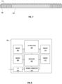
- integrated circuit product 202 includes processor 402, co-processor 404, memory circuits 406, 408, 410, and 412, interface 416, and thermal controller 414.
- processor 402 is a microprocessor, central processing unit, graphics processing unit, accelerated processing unit, digital signal processor, or other processing circuit.
- a separate thermal controller 414 is not included.
- thermal controller 414 is implemented using software (which includes firmware) executing on processor 402 or co-processor 404 or by a combination of software and hardware.
- Software as described herein, may be encoded in memory 406, 408, 410, or 412 or at least one other tangible (i.e., non-transitory) computer readable medium.
- a tangible computer-readable medium includes at least a disk, tape, or other magnetic, optical, or electronic storage medium.
- thermal controller 414 generates digital code SEL and communicates digital code SEL or the associated selectively enabled power signals to backside of integrated circuit product 202.
- digital code SEL also includes signals that interface 416 communicates to heat exchanger 210 via external signals for selectively enabling at least one electrode of the second set of electrodes of heat exchanger 210.
- thermal controller 414 includes temperature sensors (e.g., diodes on integrated circuit product 202) that are distributed across the active side of integrated circuit product 202. The temperature sensors provide temperature information to thermal controller 414 to identify hot spots of integrated circuit product 202 during operation.
- thermal controller 414 determines temperature differences for a region of the integrated circuit product and other regions of integrated circuit product 210 and compares those temperature differences to a threshold temperature difference that corresponds to a hot spot, to detect a hot spot of integrated circuit product 202.
- thermal controller 414 uses workload information for integrated circuit product 200 as a proxy for temperature information or in addition to temperature information to identify hot spots of integrated circuit product 202.
- thermal controller 414 can use workload information (e.g., program flow information) for processor 402 and co-processor 404. If the workload information indicates that co-processor 404 is operating in a high-power mode, thermal controller 414 enables one or more electrodes proximate to co-processor 404 to generate one or more corresponding high thermal conductivity path (e.g., high thermal conductivity path 216 or high thermal conductivity path 218) between hot spots of integrated circuit product 202 generated by co-processor 404 and heat exchanger 210.
- workload information e.g., program flow information
- thermal controller 414 enables one or more electrodes proximate to co-processor 404 to generate one or more corresponding high thermal conductivity path (e.g., high thermal conductivity path 216 or high thermal conductivity path 218) between hot spots of integrated circuit product 202 generated by co-processor
- thermal controller 414 periodically performs hot spot detection and updates the selected electrodes to change the location of a high thermal conductivity path between a hot spot and heat exchanger 210 or generates additional high thermal conductivity path between additional hot spots and heat exchanger 210.
- thermal controller 414 receives information regarding which core of a multi-core integrated circuit executes a workload and thermal controller 414 updates selected electrodes to generate a high thermal conductivity path between a hot spot associated with the core executing the workload and heat exchanger 210.
- Thermal controller 414 updates the selected electrodes to generate a high thermal conductivity path in another location executing the workload or to disable the path and randomly disperse the thermally conductive particles through the thermal interface material for uniform cooling of all cores of the integrated circuit die.
- thermal controller 414 disables the associated electrodes for a previously enabled high thermal conductivity path.
- the first set of electrodes on the backside of integrated circuit product 202 is tailored to predetermined hot spots of integrated circuit product 202, having higher density in a region associated with higher power consumption and lower density in regions associated lower power consumption, as illustrated in Fig. 9 .
- the electrodes of Figs 5, 6 , and 9 are illustrated as square conductive pads, in other embodiments, the electrodes have different geometries (e.g., rectangular, rhombus, or irregular shape).
- thermal management system has been described in embodiments in which dielectrophoretic force is used to align thermally conductive particles suspended in a thermal interface material to reduce the thermal resistance of a path in the thermal interface material between hot spots of integrated circuit product 202 and heat exchanger 210, one of skill in the art will appreciate that the teachings herein can be utilized with electrophoresis, magnetophoretic migration of thermally conductive particles, or electromagnetophoretic migration of thermally conductive particles to generate high thermal conductivity paths of the thermal interface material between hot spots of integrated circuit product 202 and heat exchanger 210.
- thermal interface material 208 includes magnetic thermally conductive particles (e.g., iron-oxide particles coated in gold) and a magnetic field gradient causes magnetophoretic migration of the thermally conductive particles to form a path with high thermal conductivity as compared to the thermal conductivity of a fluid with randomly distributed thermally conductive particles.
- An embodiment using electromagnetophoresis uses electrodes or real magnets to generate a magnetic field that exerts a force on the particles to excite, translate, or align particles to form a path with high thermal conductivity as compared to the thermal conductivity of a fluid with randomly distributed thermally conductive particles using migration of the thermally conductive particles due to the Lorenz force generated by simultaneous application of an electric current and magnetic field to the thermally conductive particles.
Landscapes
- Semiconductor Integrated Circuits (AREA)
- Cooling Or The Like Of Semiconductors Or Solid State Devices (AREA)
- Cooling Or The Like Of Electrical Apparatus (AREA)
- Chemical & Material Sciences (AREA)
- Engineering & Computer Science (AREA)
- Materials Engineering (AREA)
- Compositions Of Macromolecular Compounds (AREA)
Claims (15)
- Thermomanagementsystem, umfassend:eine integrierte Schaltung, die eine aktive Seite einschließlich einer Steuerschaltung und eine Rückseite einschließlich eines ersten Satzes von Elektroden, die über die Rückseite verteilt sind, aufweist;einen Wärmetauscher, der eine Oberfläche einschließlich eines zweiten Satzes von Elektroden aufweist; undein thermisches Schnittstellenmaterial einschließlich thermisch leitfähiger Partikel, die in einem Fluid suspendiert sind, wobei das thermische Schnittstellenmaterial zwischen der Rückseite der integrierten Schaltung und der Oberfläche des Wärmetauschers angeordnet ist, wobei das thermische Schnittstellenmaterial mit der Rückseite der integrierten Schaltung und der Oberfläche des Wärmetauschers in Kontakt steht,wobei die Steuerschaltung konfiguriert ist, um unter Verwendung einer ersten Elektrode des ersten Satzes von Elektroden und einer zweiten Elektrode des zweiten Satzes von Elektroden ein elektrisches Feld an das thermische Schnittstellenmaterial anzulegen, um mindestens einige der thermisch leitfähigen Partikel zwischen der ersten Elektrode und der zweiten Elektrode anzuregen.
- Thermomanagementsystem nach Anspruch 1, wobei das elektrische Feld ein ungleichmäßiges elektrisches Feld ist.
- Thermomanagementsystem nach Anspruch 1, wobei das elektrische Feld bewirkt, dass mindestens einige der thermisch leitfähigen Partikel einen Pfad mit hoher thermischer Leitfähigkeit des thermischen Schnittstellenmaterials zwischen der ersten Elektrode und der zweiten Elektrode ausbilden, wobei der Pfad mit hoher thermischer Leitfähigkeit einen geringeren thermischen Widerstand als ein Bereich des thermischen Schnittstellenmaterials aufweist, der zufällig verteilte thermisch leitfähige Partikel, die in dem Fluid suspendiert sind, aufweist.
- Thermomanagementsystem nach Anspruch 1, wobei sich die erste Elektrode nahe einer Hotspotstelle der integrierten Schaltung befindet.
- Thermomanagementsystem nach Anspruch 1, wobei das elektrische Feld unter Verwendung eines Wechselstroms, der durch die integrierte Schaltung bereitgestellt wird, erzeugt wird.
- Thermomanagementsystem nach Anspruch 1, wobei das elektrische Feld ein Wechselstromfeld ist, das eine Stärke, Frequenz, Wellenform und Phase, die durch die Steuerschaltung bestimmt werden, aufweist.
- Thermomanagementsystem nach Anspruch 1, wobei ein Radius, eine erste Permittivität und eine erste Leitfähigkeit der thermisch leitfähigen Partikel und eine zweite Permittivität und eine zweite Leitfähigkeit des Fluids Werte aufweisen, die eine Verkettung der thermisch leitfähigen Partikel in dem Fluid als Reaktion auf das elektrische Feld bewirken.
- Thermomanagementsystem nach Anspruch 1, wobei die erste Elektrode und die zweite Elektrode ein asymmetrisches Paar Elektroden sind.
- Thermomanagementsystem nach Anspruch 1, 2, 3, 4, 5, 6, 7 oder 8, wobei die Steuerschaltung konfiguriert ist, um die erste Elektrode aus dem ersten Satz von Elektroden basierend auf einer Hotspotstelle auszuwählen, und wobei das Thermomanagementsystem ferner umfasst:eine Vielzahl von Sensoren, die konfiguriert sind, um lokale Temperaturen der integrierten Schaltung zu erfassen,wobei die Hotspotstelle basierend auf Temperaturinformationen, die durch die Vielzahl von Sensoren bereitgestellt werden, identifiziert wird,wobei die Steuerschaltung konfiguriert ist, um die Hotspotstelle regelmäßig zu aktualisieren und eine dritte Elektrode des ersten Satzes von Elektroden gemäß einer aktualisierten Hotspotstelle zu aktivieren.
- Thermomanagementsystem nach Anspruch 1, 2, 3, 4, 5, 6, 7 oder 8,wobei die Steuerschaltung konfiguriert ist, um die erste Elektrode aus dem ersten Satz von Elektroden basierend auf einer Hotspotstelle auszuwählen, undwobei die Hotspotstelle basierend auf Arbeitslastinformationen der integrierten Schaltung identifiziert wird, wobei die Steuerschaltung konfiguriert ist, um die Hotspotstelle regelmäßig zu aktualisieren und eine dritte Elektrode des ersten Satzes von Elektroden gemäß einer aktualisierten Hotspotstelle zu aktivieren.
- Verfahren für ein Thermomanagement eines integrierten Schaltungsprodukts, das Verfahren umfassend:Auswählen einer ersten Elektrode aus einem ersten Satz von Elektroden, die über eine Rückseite einer integrierten Schaltung verteilt sind, und einer zweiten Elektrode eines zweiten Satzes von Elektroden einer Oberfläche eines Wärmetauschers; undAnlegen eines elektrischen Felds an ein thermisches Schnittstellenmaterial unter Verwendung der ersten Elektrode und der zweiten Elektrode, wobei das thermische Schnittstellenmaterial thermisch leitfähige Partikel, die in einer Flüssigkeit suspendiert sind, einschließt, wobei das thermische Schnittstellenmaterial zwischen der Rückseite des integrierten Schaltung und der Oberfläche des Wärmetauschers angeordnet ist, wobei das thermische Schnittstellenmaterial in Kontakt mit der Rückseite der integrierten Schaltung und der Oberfläche des Wärmetauschers steht, wobei das elektrische Feld mindestens einige der thermisch leitfähigen Partikel zwischen der ersten Elektrode und der zweiten Elektrode anregt.
- Verfahren nach Anspruch 11,wobei das elektrische Feld ein ungleichmäßiges elektrisches Feld ist undwobei das elektrische Feld bewirkt, dass sich mindestens einige der thermisch leitfähigen Partikel ausrichten, wobei dadurch ein Pfad mit hoher thermischer Leitfähigkeit des thermischen Schnittstellenmaterials zwischen der ersten Elektrode und der zweiten Elektrode ausgebildet wird, wobei der Pfad mit hoher thermischer Leitfähigkeit einen niedrigeren thermischen Widerstand als ein Bereich des thermischen Schnittstellenmaterials aufweist, der zufällig verteilte thermisch leitfähige Partikel, die in dem Fluid suspendiert sind, aufweist.
- Verfahren nach Anspruch 11 oder 12, ferner umfassend:Identifizieren einer Hotspotstelle der integrierten Schaltung;Erfassen der lokalen Temperaturen der integrierten Schaltung; undregelmäßiges Aktualisieren der Hotspotstelle der integrierten Schaltung und Aktivieren einer dritten Elektrode des ersten Satzes von Elektroden gemäß einer aktualisierten Hotspotstelle,wobei die erste Elektrode basierend auf der Hotspotstelle ausgewählt wird undwobei die Hotspotstelle basierend auf den lokalen Temperaturen identifiziert wird.
- Verfahren nach Anspruch 11 oder 12, ferner umfassend:Identifizieren einer Hotspotstelle der integrierten Schaltung; undregelmäßiges Aktualisieren der Hotspotstelle der integrierten Schaltung und Aktivieren einer dritten Elektrode des ersten Satzes von Elektroden gemäß einer aktualisierten Hotspotstelle,wobei die erste Elektrode basierend auf der Hotspotstelle ausgewählt wird undwobei die Hotspotstelle basierend auf Arbeitslastinformationen identifiziert wird.
- Verfahren nach Anspruch 11 oder 12, wobei ein Radius, eine erste Permittivität und eine erste Leitfähigkeit der thermisch leitfähigen Partikel und eine zweite Permittivität und eine zweite Leitfähigkeit des Fluids Werte aufweisen, die die Verkettung der thermisch leitfähigen Partikel in dem Fluid als Reaktion auf das elektrische Feld bewirken.
Applications Claiming Priority (2)
| Application Number | Priority Date | Filing Date | Title |
|---|---|---|---|
| US16/729,924 US11201104B2 (en) | 2019-12-30 | 2019-12-30 | Thermal management using variation of thermal resistance of thermal interface |
| PCT/US2020/066772 WO2021138177A1 (en) | 2019-12-30 | 2020-12-23 | Thermal management using variation of thermal resistance of thermal interface |
Publications (3)
| Publication Number | Publication Date |
|---|---|
| EP4085481A1 EP4085481A1 (de) | 2022-11-09 |
| EP4085481A4 EP4085481A4 (de) | 2023-12-13 |
| EP4085481B1 true EP4085481B1 (de) | 2025-01-29 |
Family
ID=76547752
Family Applications (1)
| Application Number | Title | Priority Date | Filing Date |
|---|---|---|---|
| EP20908542.2A Active EP4085481B1 (de) | 2019-12-30 | 2020-12-23 | Thermische verwaltung mit variation der thermischen beständigkeit einer thermischen schnittstelle |
Country Status (6)
| Country | Link |
|---|---|
| US (1) | US11201104B2 (de) |
| EP (1) | EP4085481B1 (de) |
| JP (1) | JP7705400B2 (de) |
| KR (1) | KR102903053B1 (de) |
| CN (1) | CN114868243B (de) |
| WO (1) | WO2021138177A1 (de) |
Families Citing this family (2)
| Publication number | Priority date | Publication date | Assignee | Title |
|---|---|---|---|---|
| WO2023086216A2 (en) * | 2021-10-28 | 2023-05-19 | Worcester Polytechnic Institute | Gravity independent liquid cooling for electronics |
| CN115935703A (zh) * | 2023-01-04 | 2023-04-07 | 深圳先进电子材料国际创新研究院 | 复合材料体系内部界面热阻确定方法 |
Family Cites Families (17)
| Publication number | Priority date | Publication date | Assignee | Title |
|---|---|---|---|---|
| US4548862A (en) | 1984-09-04 | 1985-10-22 | Minnesota Mining And Manufacturing Company | Flexible tape having bridges of electrically conductive particles extending across its pressure-sensitive adhesive layer |
| US20050061496A1 (en) | 2003-09-24 | 2005-03-24 | Matabayas James Christopher | Thermal interface material with aligned carbon nanotubes |
| US20050127500A1 (en) | 2003-12-10 | 2005-06-16 | International Business Machines Corporation | Local reduction of compliant thermally conductive material layer thickness on chips |
| US8011424B2 (en) * | 2005-06-09 | 2011-09-06 | The United States Of America, As Represented By The Secretary Of The Navy | System and method for convective heat transfer utilizing a particulate solution in a time varying field |
| US7394657B2 (en) | 2006-02-21 | 2008-07-01 | International Business Machines Corporation | Method of obtaining enhanced localized thermal interface regions by particle stacking |
| JP5315688B2 (ja) * | 2007-12-28 | 2013-10-16 | 株式会社ニコン | 積層型半導体装置 |
| US20100039208A1 (en) * | 2008-01-15 | 2010-02-18 | Epstein Richard I | High-frequency, thin-film liquid crystal thermal switches |
| US20090277608A1 (en) * | 2008-05-07 | 2009-11-12 | Kamins Theodore I | Thermal Control Via Adjustable Thermal Links |
| KR101476424B1 (ko) | 2008-06-23 | 2014-12-29 | 서울반도체 주식회사 | 반도체칩용 열계면 재료 및 그것의 형성방법 |
| US20130062789A1 (en) * | 2011-09-08 | 2013-03-14 | International Business Machines Corporation | Manufacturing a filling of a gap region |
| JP2013185728A (ja) * | 2012-03-07 | 2013-09-19 | Kri Inc | 熱流制御デバイス |
| KR101491328B1 (ko) * | 2013-10-14 | 2015-02-06 | 현대자동차주식회사 | 차량 전력전자부품 하우징용 구조물 |
| KR101567141B1 (ko) * | 2013-10-15 | 2015-11-06 | 현대자동차주식회사 | 전기전자부품 하우징의 열전도도 제어 장치 |
| JP6199158B2 (ja) * | 2013-11-05 | 2017-09-20 | 東洋ゴム工業株式会社 | 熱伝導率可変材料 |
| CN106158790B (zh) * | 2015-04-10 | 2018-11-16 | 台达电子工业股份有限公司 | 功率模块及其热界面结构 |
| KR102105227B1 (ko) | 2016-11-25 | 2020-04-27 | 주식회사 엘지화학 | 전기 절연성 방열 시트 및 이의 제조방법 |
| DE102017217105A1 (de) * | 2017-09-26 | 2019-03-28 | Robert Bosch Gmbh | Kühlvorrichtung und Verfahren zur Kühlung eines zu kühlenden Elements |
-
2019
- 2019-12-30 US US16/729,924 patent/US11201104B2/en active Active
-
2020
- 2020-12-23 EP EP20908542.2A patent/EP4085481B1/de active Active
- 2020-12-23 WO PCT/US2020/066772 patent/WO2021138177A1/en not_active Ceased
- 2020-12-23 JP JP2022537363A patent/JP7705400B2/ja active Active
- 2020-12-23 CN CN202080087665.4A patent/CN114868243B/zh active Active
- 2020-12-23 KR KR1020227025077A patent/KR102903053B1/ko active Active
Also Published As
| Publication number | Publication date |
|---|---|
| WO2021138177A1 (en) | 2021-07-08 |
| JP2023508865A (ja) | 2023-03-06 |
| EP4085481A4 (de) | 2023-12-13 |
| US20210202351A1 (en) | 2021-07-01 |
| EP4085481A1 (de) | 2022-11-09 |
| KR102903053B1 (ko) | 2025-12-22 |
| CN114868243B (zh) | 2026-03-17 |
| JP7705400B2 (ja) | 2025-07-09 |
| CN114868243A (zh) | 2022-08-05 |
| US11201104B2 (en) | 2021-12-14 |
| KR20220123244A (ko) | 2022-09-06 |
Similar Documents
| Publication | Publication Date | Title |
|---|---|---|
| KR100970031B1 (ko) | 마이크로채널 및 마이크로채널의 박막 열전 냉각 장치 내의냉각제 흐름을 이용한 집적회로 다이 냉각 | |
| KR20240128916A (ko) | 마이크로전자기기에서의 열전 냉각 | |
| US6563227B1 (en) | Temperature control method for integrated circuit | |
| EP4085481B1 (de) | Thermische verwaltung mit variation der thermischen beständigkeit einer thermischen schnittstelle | |
| US8441092B2 (en) | Thermoelectric cooler system, method and device | |
| US9847272B2 (en) | Three-dimensional integrated circuit structures providing thermoelectric cooling and methods for cooling such integrated circuit structures | |
| KR20070015582A (ko) | 써모일렉트릭 나노-와이어 디바이스 | |
| CN101427368A (zh) | 电渗透泵和微通道 | |
| CN102130289B (zh) | 热电器件以及热电器件阵列 | |
| US11462457B2 (en) | Using a thermoelectric cooler to reduce heat transfer between heat-conducting plates | |
| US7105382B2 (en) | Self-aligned electrodes contained within the trenches of an electroosmotic pump | |
| US7259458B2 (en) | Integrated circuit with increased heat transfer | |
| CA2949931A1 (en) | Integrated, three-dimensional cell configuration, integrated cooling array and cell-based integrated circuit | |
| Mandalapu et al. | Design, fabrication, and testing of a liquid cooling platform for high power 3D-ICs | |
| CN108666296B (zh) | 晶体管结构 | |
| US20250112104A1 (en) | Radiator type heating element for integrated circuits | |
| CN110571206A (zh) | 半导体结构及其形成方法和芯片的形成方法 | |
| Li et al. | Microembossed copper microchannel heat sink for high‐density cooling in electronics | |
| TW202525023A (zh) | 半導體結構的製作方法 | |
| Melamed et al. | Investigation into the thermal effects of thinning stacked dies in three-dimensional integrated circuits | |
| US20180196022A1 (en) | Gas sensor |
Legal Events
| Date | Code | Title | Description |
|---|---|---|---|
| STAA | Information on the status of an ep patent application or granted ep patent |
Free format text: STATUS: THE INTERNATIONAL PUBLICATION HAS BEEN MADE |
|
| PUAI | Public reference made under article 153(3) epc to a published international application that has entered the european phase |
Free format text: ORIGINAL CODE: 0009012 |
|
| STAA | Information on the status of an ep patent application or granted ep patent |
Free format text: STATUS: REQUEST FOR EXAMINATION WAS MADE |
|
| 17P | Request for examination filed |
Effective date: 20220622 |
|
| AK | Designated contracting states |
Kind code of ref document: A1 Designated state(s): AL AT BE BG CH CY CZ DE DK EE ES FI FR GB GR HR HU IE IS IT LI LT LU LV MC MK MT NL NO PL PT RO RS SE SI SK SM TR |
|
| DAV | Request for validation of the european patent (deleted) | ||
| DAX | Request for extension of the european patent (deleted) | ||
| REG | Reference to a national code |
Ref country code: DE Free format text: PREVIOUS MAIN CLASS: H01L0023440000 Ref country code: DE Ref legal event code: R079 Ref document number: 602020045669 Country of ref document: DE Free format text: PREVIOUS MAIN CLASS: H01L0023440000 Ipc: H01L0023373000 |
|
| A4 | Supplementary search report drawn up and despatched |
Effective date: 20231109 |
|
| RIC1 | Information provided on ipc code assigned before grant |
Ipc: H01L 23/48 20060101ALN20231103BHEP Ipc: H01L 23/34 20060101ALN20231103BHEP Ipc: H01L 23/42 20060101ALI20231103BHEP Ipc: H01L 23/373 20060101AFI20231103BHEP |
|
| GRAP | Despatch of communication of intention to grant a patent |
Free format text: ORIGINAL CODE: EPIDOSNIGR1 |
|
| STAA | Information on the status of an ep patent application or granted ep patent |
Free format text: STATUS: GRANT OF PATENT IS INTENDED |
|
| RIC1 | Information provided on ipc code assigned before grant |
Ipc: H01L 23/48 20060101ALN20240816BHEP Ipc: H01L 23/34 20060101ALN20240816BHEP Ipc: H01L 23/42 20060101ALI20240816BHEP Ipc: H01L 23/373 20060101AFI20240816BHEP |
|
| INTG | Intention to grant announced |
Effective date: 20240828 |
|
| GRAS | Grant fee paid |
Free format text: ORIGINAL CODE: EPIDOSNIGR3 |
|
| GRAA | (expected) grant |
Free format text: ORIGINAL CODE: 0009210 |
|
| STAA | Information on the status of an ep patent application or granted ep patent |
Free format text: STATUS: THE PATENT HAS BEEN GRANTED |
|
| P01 | Opt-out of the competence of the unified patent court (upc) registered |
Free format text: CASE NUMBER: APP_66659/2024 Effective date: 20241217 |
|
| AK | Designated contracting states |
Kind code of ref document: B1 Designated state(s): AL AT BE BG CH CY CZ DE DK EE ES FI FR GB GR HR HU IE IS IT LI LT LU LV MC MK MT NL NO PL PT RO RS SE SI SK SM TR |
|
| REG | Reference to a national code |
Ref country code: GB Ref legal event code: FG4D |
|
| REG | Reference to a national code |
Ref country code: CH Ref legal event code: EP |
|
| REG | Reference to a national code |
Ref country code: DE Ref legal event code: R096 Ref document number: 602020045669 Country of ref document: DE |
|
| REG | Reference to a national code |
Ref country code: IE Ref legal event code: FG4D |
|
| REG | Reference to a national code |
Ref country code: NL Ref legal event code: MP Effective date: 20250129 |
|
| PG25 | Lapsed in a contracting state [announced via postgrant information from national office to epo] |
Ref country code: NL Free format text: LAPSE BECAUSE OF FAILURE TO SUBMIT A TRANSLATION OF THE DESCRIPTION OR TO PAY THE FEE WITHIN THE PRESCRIBED TIME-LIMIT Effective date: 20250129 |
|
| PG25 | Lapsed in a contracting state [announced via postgrant information from national office to epo] |
Ref country code: RS Free format text: LAPSE BECAUSE OF FAILURE TO SUBMIT A TRANSLATION OF THE DESCRIPTION OR TO PAY THE FEE WITHIN THE PRESCRIBED TIME-LIMIT Effective date: 20250429 |
|
| PG25 | Lapsed in a contracting state [announced via postgrant information from national office to epo] |
Ref country code: FI Free format text: LAPSE BECAUSE OF FAILURE TO SUBMIT A TRANSLATION OF THE DESCRIPTION OR TO PAY THE FEE WITHIN THE PRESCRIBED TIME-LIMIT Effective date: 20250129 |
|
| PG25 | Lapsed in a contracting state [announced via postgrant information from national office to epo] |
Ref country code: PL Free format text: LAPSE BECAUSE OF FAILURE TO SUBMIT A TRANSLATION OF THE DESCRIPTION OR TO PAY THE FEE WITHIN THE PRESCRIBED TIME-LIMIT Effective date: 20250129 |
|
| PG25 | Lapsed in a contracting state [announced via postgrant information from national office to epo] |
Ref country code: ES Free format text: LAPSE BECAUSE OF FAILURE TO SUBMIT A TRANSLATION OF THE DESCRIPTION OR TO PAY THE FEE WITHIN THE PRESCRIBED TIME-LIMIT Effective date: 20250129 |
|
| REG | Reference to a national code |
Ref country code: LT Ref legal event code: MG9D |
|
| PG25 | Lapsed in a contracting state [announced via postgrant information from national office to epo] |
Ref country code: IS Free format text: LAPSE BECAUSE OF FAILURE TO SUBMIT A TRANSLATION OF THE DESCRIPTION OR TO PAY THE FEE WITHIN THE PRESCRIBED TIME-LIMIT Effective date: 20250529 Ref country code: NO Free format text: LAPSE BECAUSE OF FAILURE TO SUBMIT A TRANSLATION OF THE DESCRIPTION OR TO PAY THE FEE WITHIN THE PRESCRIBED TIME-LIMIT Effective date: 20250429 |
|
| REG | Reference to a national code |
Ref country code: AT Ref legal event code: MK05 Ref document number: 1764346 Country of ref document: AT Kind code of ref document: T Effective date: 20250129 |
|
| PG25 | Lapsed in a contracting state [announced via postgrant information from national office to epo] |
Ref country code: HR Free format text: LAPSE BECAUSE OF FAILURE TO SUBMIT A TRANSLATION OF THE DESCRIPTION OR TO PAY THE FEE WITHIN THE PRESCRIBED TIME-LIMIT Effective date: 20250129 |
|
| PG25 | Lapsed in a contracting state [announced via postgrant information from national office to epo] |
Ref country code: LV Free format text: LAPSE BECAUSE OF FAILURE TO SUBMIT A TRANSLATION OF THE DESCRIPTION OR TO PAY THE FEE WITHIN THE PRESCRIBED TIME-LIMIT Effective date: 20250129 Ref country code: PT Free format text: LAPSE BECAUSE OF FAILURE TO SUBMIT A TRANSLATION OF THE DESCRIPTION OR TO PAY THE FEE WITHIN THE PRESCRIBED TIME-LIMIT Effective date: 20250529 |
|
| PG25 | Lapsed in a contracting state [announced via postgrant information from national office to epo] |
Ref country code: GR Free format text: LAPSE BECAUSE OF FAILURE TO SUBMIT A TRANSLATION OF THE DESCRIPTION OR TO PAY THE FEE WITHIN THE PRESCRIBED TIME-LIMIT Effective date: 20250430 Ref country code: BG Free format text: LAPSE BECAUSE OF FAILURE TO SUBMIT A TRANSLATION OF THE DESCRIPTION OR TO PAY THE FEE WITHIN THE PRESCRIBED TIME-LIMIT Effective date: 20250129 |
|
| PG25 | Lapsed in a contracting state [announced via postgrant information from national office to epo] |
Ref country code: AT Free format text: LAPSE BECAUSE OF FAILURE TO SUBMIT A TRANSLATION OF THE DESCRIPTION OR TO PAY THE FEE WITHIN THE PRESCRIBED TIME-LIMIT Effective date: 20250129 |
|
| PG25 | Lapsed in a contracting state [announced via postgrant information from national office to epo] |
Ref country code: SE Free format text: LAPSE BECAUSE OF FAILURE TO SUBMIT A TRANSLATION OF THE DESCRIPTION OR TO PAY THE FEE WITHIN THE PRESCRIBED TIME-LIMIT Effective date: 20250129 |
|
| PG25 | Lapsed in a contracting state [announced via postgrant information from national office to epo] |
Ref country code: SM Free format text: LAPSE BECAUSE OF FAILURE TO SUBMIT A TRANSLATION OF THE DESCRIPTION OR TO PAY THE FEE WITHIN THE PRESCRIBED TIME-LIMIT Effective date: 20250129 |
|
| PG25 | Lapsed in a contracting state [announced via postgrant information from national office to epo] |
Ref country code: DK Free format text: LAPSE BECAUSE OF FAILURE TO SUBMIT A TRANSLATION OF THE DESCRIPTION OR TO PAY THE FEE WITHIN THE PRESCRIBED TIME-LIMIT Effective date: 20250129 |
|
| PG25 | Lapsed in a contracting state [announced via postgrant information from national office to epo] |
Ref country code: IT Free format text: LAPSE BECAUSE OF FAILURE TO SUBMIT A TRANSLATION OF THE DESCRIPTION OR TO PAY THE FEE WITHIN THE PRESCRIBED TIME-LIMIT Effective date: 20250129 |
|
| PG25 | Lapsed in a contracting state [announced via postgrant information from national office to epo] |
Ref country code: EE Free format text: LAPSE BECAUSE OF FAILURE TO SUBMIT A TRANSLATION OF THE DESCRIPTION OR TO PAY THE FEE WITHIN THE PRESCRIBED TIME-LIMIT Effective date: 20250129 Ref country code: CZ Free format text: LAPSE BECAUSE OF FAILURE TO SUBMIT A TRANSLATION OF THE DESCRIPTION OR TO PAY THE FEE WITHIN THE PRESCRIBED TIME-LIMIT Effective date: 20250129 |
|
| PG25 | Lapsed in a contracting state [announced via postgrant information from national office to epo] |
Ref country code: RO Free format text: LAPSE BECAUSE OF FAILURE TO SUBMIT A TRANSLATION OF THE DESCRIPTION OR TO PAY THE FEE WITHIN THE PRESCRIBED TIME-LIMIT Effective date: 20250129 |
|
| PG25 | Lapsed in a contracting state [announced via postgrant information from national office to epo] |
Ref country code: SK Free format text: LAPSE BECAUSE OF FAILURE TO SUBMIT A TRANSLATION OF THE DESCRIPTION OR TO PAY THE FEE WITHIN THE PRESCRIBED TIME-LIMIT Effective date: 20250129 |
|
| REG | Reference to a national code |
Ref country code: DE Ref legal event code: R097 Ref document number: 602020045669 Country of ref document: DE |
|
| REG | Reference to a national code |
Ref country code: DE Ref legal event code: R079 Ref document number: 602020045669 Country of ref document: DE Free format text: PREVIOUS MAIN CLASS: H01L0023373000 Ipc: H10W0040250000 |
|
| PLBE | No opposition filed within time limit |
Free format text: ORIGINAL CODE: 0009261 |
|
| STAA | Information on the status of an ep patent application or granted ep patent |
Free format text: STATUS: NO OPPOSITION FILED WITHIN TIME LIMIT |
|
| 26N | No opposition filed |
Effective date: 20251030 |
|
| PGFP | Annual fee paid to national office [announced via postgrant information from national office to epo] |
Ref country code: DE Payment date: 20251113 Year of fee payment: 6 |
|
| PGFP | Annual fee paid to national office [announced via postgrant information from national office to epo] |
Ref country code: GB Payment date: 20251203 Year of fee payment: 6 |