EP4084126A1 - Anode für festkörperbatterie sowie festkörperbatterie damit - Google Patents
Anode für festkörperbatterie sowie festkörperbatterie damit Download PDFInfo
- Publication number
- EP4084126A1 EP4084126A1 EP21892164.1A EP21892164A EP4084126A1 EP 4084126 A1 EP4084126 A1 EP 4084126A1 EP 21892164 A EP21892164 A EP 21892164A EP 4084126 A1 EP4084126 A1 EP 4084126A1
- Authority
- EP
- European Patent Office
- Prior art keywords
- negative electrode
- solid
- state battery
- solid electrolyte
- lithium
- Prior art date
- Legal status (The legal status is an assumption and is not a legal conclusion. Google has not performed a legal analysis and makes no representation as to the accuracy of the status listed.)
- Pending
Links
Images


Classifications
-
- H—ELECTRICITY
- H01—ELECTRIC ELEMENTS
- H01M—PROCESSES OR MEANS, e.g. BATTERIES, FOR THE DIRECT CONVERSION OF CHEMICAL ENERGY INTO ELECTRICAL ENERGY
- H01M4/00—Electrodes
- H01M4/02—Electrodes composed of, or comprising, active material
- H01M4/13—Electrodes for accumulators with non-aqueous electrolyte, e.g. for lithium-accumulators; Processes of manufacture thereof
- H01M4/133—Electrodes based on carbonaceous material, e.g. graphite-intercalation compounds or CFx
-
- H—ELECTRICITY
- H01—ELECTRIC ELEMENTS
- H01M—PROCESSES OR MEANS, e.g. BATTERIES, FOR THE DIRECT CONVERSION OF CHEMICAL ENERGY INTO ELECTRICAL ENERGY
- H01M10/00—Secondary cells; Manufacture thereof
- H01M10/05—Accumulators with non-aqueous electrolyte
- H01M10/052—Li-accumulators
- H01M10/0525—Rocking-chair batteries, i.e. batteries with lithium insertion or intercalation in both electrodes; Lithium-ion batteries
-
- H—ELECTRICITY
- H01—ELECTRIC ELEMENTS
- H01M—PROCESSES OR MEANS, e.g. BATTERIES, FOR THE DIRECT CONVERSION OF CHEMICAL ENERGY INTO ELECTRICAL ENERGY
- H01M10/00—Secondary cells; Manufacture thereof
- H01M10/05—Accumulators with non-aqueous electrolyte
- H01M10/056—Accumulators with non-aqueous electrolyte characterised by the materials used as electrolytes, e.g. mixed inorganic/organic electrolytes
- H01M10/0561—Accumulators with non-aqueous electrolyte characterised by the materials used as electrolytes, e.g. mixed inorganic/organic electrolytes the electrolyte being constituted of inorganic materials only
- H01M10/0562—Solid materials
-
- H—ELECTRICITY
- H01—ELECTRIC ELEMENTS
- H01M—PROCESSES OR MEANS, e.g. BATTERIES, FOR THE DIRECT CONVERSION OF CHEMICAL ENERGY INTO ELECTRICAL ENERGY
- H01M4/00—Electrodes
- H01M4/02—Electrodes composed of, or comprising, active material
-
- H—ELECTRICITY
- H01—ELECTRIC ELEMENTS
- H01M—PROCESSES OR MEANS, e.g. BATTERIES, FOR THE DIRECT CONVERSION OF CHEMICAL ENERGY INTO ELECTRICAL ENERGY
- H01M4/00—Electrodes
- H01M4/02—Electrodes composed of, or comprising, active material
- H01M4/04—Processes of manufacture in general
- H01M4/0402—Methods of deposition of the material
-
- H—ELECTRICITY
- H01—ELECTRIC ELEMENTS
- H01M—PROCESSES OR MEANS, e.g. BATTERIES, FOR THE DIRECT CONVERSION OF CHEMICAL ENERGY INTO ELECTRICAL ENERGY
- H01M4/00—Electrodes
- H01M4/02—Electrodes composed of, or comprising, active material
- H01M4/36—Selection of substances as active materials, active masses, active liquids
- H01M4/362—Composites
- H01M4/366—Composites as layered products
-
- H—ELECTRICITY
- H01—ELECTRIC ELEMENTS
- H01M—PROCESSES OR MEANS, e.g. BATTERIES, FOR THE DIRECT CONVERSION OF CHEMICAL ENERGY INTO ELECTRICAL ENERGY
- H01M4/00—Electrodes
- H01M4/02—Electrodes composed of, or comprising, active material
- H01M4/36—Selection of substances as active materials, active masses, active liquids
- H01M4/58—Selection of substances as active materials, active masses, active liquids of inorganic compounds other than oxides or hydroxides, e.g. sulfides, selenides, tellurides, halogenides or LiCoFy; of polyanionic structures, e.g. phosphates, silicates or borates
- H01M4/583—Carbonaceous material, e.g. graphite-intercalation compounds or CFx
- H01M4/587—Carbonaceous material, e.g. graphite-intercalation compounds or CFx for inserting or intercalating light metals
-
- H—ELECTRICITY
- H01—ELECTRIC ELEMENTS
- H01M—PROCESSES OR MEANS, e.g. BATTERIES, FOR THE DIRECT CONVERSION OF CHEMICAL ENERGY INTO ELECTRICAL ENERGY
- H01M4/00—Electrodes
- H01M4/02—Electrodes composed of, or comprising, active material
- H01M4/62—Selection of inactive substances as ingredients for active masses, e.g. binders, fillers
- H01M4/621—Binders
- H01M4/622—Binders being polymers
- H01M4/623—Binders being polymers fluorinated polymers
-
- H—ELECTRICITY
- H01—ELECTRIC ELEMENTS
- H01M—PROCESSES OR MEANS, e.g. BATTERIES, FOR THE DIRECT CONVERSION OF CHEMICAL ENERGY INTO ELECTRICAL ENERGY
- H01M4/00—Electrodes
- H01M4/02—Electrodes composed of, or comprising, active material
- H01M4/62—Selection of inactive substances as ingredients for active masses, e.g. binders, fillers
- H01M4/624—Electric conductive fillers
- H01M4/625—Carbon or graphite
-
- H—ELECTRICITY
- H01—ELECTRIC ELEMENTS
- H01M—PROCESSES OR MEANS, e.g. BATTERIES, FOR THE DIRECT CONVERSION OF CHEMICAL ENERGY INTO ELECTRICAL ENERGY
- H01M4/00—Electrodes
- H01M4/02—Electrodes composed of, or comprising, active material
- H01M4/62—Selection of inactive substances as ingredients for active masses, e.g. binders, fillers
- H01M4/628—Inhibitors, e.g. gassing inhibitors, corrosion inhibitors
-
- H—ELECTRICITY
- H01—ELECTRIC ELEMENTS
- H01M—PROCESSES OR MEANS, e.g. BATTERIES, FOR THE DIRECT CONVERSION OF CHEMICAL ENERGY INTO ELECTRICAL ENERGY
- H01M4/00—Electrodes
- H01M4/02—Electrodes composed of, or comprising, active material
- H01M2004/021—Physical characteristics, e.g. porosity, surface area
-
- H—ELECTRICITY
- H01—ELECTRIC ELEMENTS
- H01M—PROCESSES OR MEANS, e.g. BATTERIES, FOR THE DIRECT CONVERSION OF CHEMICAL ENERGY INTO ELECTRICAL ENERGY
- H01M4/00—Electrodes
- H01M4/02—Electrodes composed of, or comprising, active material
- H01M2004/026—Electrodes composed of, or comprising, active material characterised by the polarity
- H01M2004/027—Negative electrodes
-
- H—ELECTRICITY
- H01—ELECTRIC ELEMENTS
- H01M—PROCESSES OR MEANS, e.g. BATTERIES, FOR THE DIRECT CONVERSION OF CHEMICAL ENERGY INTO ELECTRICAL ENERGY
- H01M2300/00—Electrolytes
- H01M2300/0017—Non-aqueous electrolytes
- H01M2300/0065—Solid electrolytes
- H01M2300/0068—Solid electrolytes inorganic
-
- Y—GENERAL TAGGING OF NEW TECHNOLOGICAL DEVELOPMENTS; GENERAL TAGGING OF CROSS-SECTIONAL TECHNOLOGIES SPANNING OVER SEVERAL SECTIONS OF THE IPC; TECHNICAL SUBJECTS COVERED BY FORMER USPC CROSS-REFERENCE ART COLLECTIONS [XRACs] AND DIGESTS
- Y02—TECHNOLOGIES OR APPLICATIONS FOR MITIGATION OR ADAPTATION AGAINST CLIMATE CHANGE
- Y02E—REDUCTION OF GREENHOUSE GAS [GHG] EMISSIONS, RELATED TO ENERGY GENERATION, TRANSMISSION OR DISTRIBUTION
- Y02E60/00—Enabling technologies; Technologies with a potential or indirect contribution to GHG emissions mitigation
- Y02E60/10—Energy storage using batteries
Definitions
- the present disclosure relates to a negative electrode for an all-solid-state battery that enables the provision of an all-solid-state battery exhibiting excellent contact characteristics between the negative electrode and a solid electrolyte along with improved life characteristics, and an all-solid-state battery including the same.
- Secondary batteries have been mainly applied to small fields such as mobile devices and notebook computers, but recently their application direction has been expanded to medium and large fields, and has been mainly expanded to fields where high energy and high output are required in relation to an energy storage system (ESS) or an electric vehicle (EV).
- ESS energy storage system
- EV electric vehicle
- the all-solid-state battery is a battery that uses a solid electrolyte instead of a liquid electrolyte, and has an advantage that it has higher thermal stability than an existing lithium secondary battery to which a liquid electrolyte is applied. Further, since the all-solid-state battery is advantageous over the existing lithium secondary battery in terms of high energy density and output characteristics, simplification of the manufacturing process, and enlargement/ compactness of the battery, research and interest thereon have been concentrated recently.
- the lithium metal negative electrode in the initial charge / discharge process of the battery, lithium moving from the positive electrode to the negative electrode is laminated in the form of dendrites on the surface of the negative electrode to form lithium dendrites, which has thus a drawback of deteriorating the life characteristics and stability of the battery.
- the silicon-based negative electrode also has a drawback that a large volume change is caused during the charge / discharge process, so that the life characteristics of the battery are greatly deteriorated. Therefore, there is a continuous demand for the development of a negative electrode and/or an all-solid-state battery having improved life characteristics and the like while realizing a higher capacity and energy density.
- the all-solid-state battery contains a solid electrolyte, in order to fully exhibit the performance of such an all-solid-state battery, it is necessary to ensure sufficient contact characteristics between each electrode and the solid electrolyte and to realize high ionic conductivity.
- the characteristics of the solid electrolyte due to the characteristics of the solid electrolyte, it is difficult to permeate into each electrode and it is not easy to secure a sufficient contact area.
- the present disclosure provides a negative electrode for an all-solid-state battery that enables the provision of an all-solid-state battery exhibiting excellent contact characteristics between the negative electrode and a solid electrolyte along with improved life characteristics, while exhibiting a high energy density.
- the present disclosure provides an all-solid-state battery including the negative electrode, which exhibits high energy density, improved life characteristics, excellent contact characteristics between a negative electrode and a solid electrolyte, and low interfacial resistance.
- a negative electrode for an all-solid-state battery comprising:
- an all-solid-state battery comprising:
- the negative electrode of the present disclosure not only excludes or minimally includes a separate active material layer formed three-dimensionally, such as a separate lithium metal thin film, but also includes an amorphous carbon layer containing a carbon defect structure formed of electron-deficient carbon atoms by chemically treating a crystalline carbon layer, and a plurality of nanopores.
- an amorphous carbon layer containing such a carbon defect structure By the formation of an amorphous carbon layer containing such a carbon defect structure, it is possible to eliminate or reduce an active material layer such as a lithium metal thin film formed in the form of a three-dimensional additional thin film in a battery to which an existing lithium metal negative electrode is applied, or the like. Therefore, it is possible to fundamentally suppress the growth of lithium dendrites from such a lithium metal thin film or the like.
- the amorphous carbon layer as a large number of electron-deficient carbon atoms are included in the carbon defect structure, a large number of lithium ions and/or lithium compounds containing them can be intercalated while donating electrons to these carbon atoms. Further, by using such lithium ions and the like as nuclei, lithium metal can be uniformly electrodeposited around them. Therefore, such amorphous carbon layer can induce uniform lithium electrodeposition formed two-dimensionally on the same plane, and the lithium metal thus electrodeposited can act as an active material layer having a lithium ion source. Therefore, the negative electrode of the present disclosure can realize a high energy density comparable to the case where the existing lithium metal negative electrode is applied.
- a solid electrolyte material can be filled in a large number of nanopores formed in the amorphous carbon layer, a sufficient contact area can be ensured between the negative electrode, furthermore, the lithium metal acting as the active material layer, and the solid electrolyte filled in the nanopores. Consequently, excellent contact characteristics between the negative electrode and the solid electrolyte, low interfacial resistance and high ionic conductivity can be achieved.
- the negative electrode of the present disclosure when used, it is possible to provide an all-solid-state battery which suppresses the formation of lithium dendrites, has a high energy density comparable to the case of applying a lithium metal negative electrode while exhibiting improved life characteristics, and ensures sufficient contact characteristics between the negative electrode and the solid electrolyte.
- Such an all-solid-state battery can exhibit excellent cell performance and life characteristics, and can be very preferably used as a next-generation battery applied to an electric vehicle or the like.
- a negative electrode for an all-solid-state battery comprising:
- the negative electrode of the one embodiment is manufactured by subjecting the surface of a crystalline carbon fabric providing a crystalline carbon layer to a plasma oxidation treatment, proceeding with surface coating of a metal organic framework (MOF) and carbonization thereof to form an amorphous carbon layer, and applying a slurry coating method or the like onto the amorphous carbon layer to form a solid electrolyte material, in the same manner as in a manufacturing method described later.
- MOF metal organic framework
- a large number of nanopores (vacancies) having a size of 0.5 to 2 nm, or 0.8 to 1.5 nm, or 1.0 to 1.2 nm may be formed in the carbon defect structure.
- the non-crystalline characteristics of the amorphous carbon layer, the formation of a carbon defect structure (formation of electron-deficient carbon atoms), and the formation of a large number of nanopores can be confirmed through TEM analysis, XPS analysis, Raman spectrum analysis, and BET analysis described later.
- a large number of electron-deficient carbon atoms are included in the amorphous carbon layer, and a large number of nanopores having a size of 0.5 to 2 nm, more specifically, 1.0 to 1.2 nm, are formed. Therefore, electrons are donated from the conduction band of lithium, which serves to donate electrons to the carbon atoms, to the valence band of the carbon defect structure, so that lithium having the form of a large number of lithium ions and/or a lithium compound containing the same (e.g., lithium carbide compounds in the form of Li 3 C 8 ), etc., can be well adsorbed, bonded and intercalated to the electron-deficient carbon atoms.
- the lithium ions or the like intercalated in this way function as a kind of nucleus, and lithium metal can be uniformly electrodeposited around the carbon defect structure centering on the lithium ions and the like.
- the lithium ions and the like, and lithium metal electrodeposited around them can be intercalated and formed two-dimensionally into the large number of nanopores in one example, and can act as a lithium ion source for the negative electrode. Therefore, in the negative electrode of one embodiment, the lithium ion source may be included two-dimensionally on the same plane as (or inside) the amorphous carbon layer.
- such amorphous carbon layer itself can function as an active material layer having a lithium ion source (lithium metal electrodeposited on an amorphous carbon layer) contained in a two-dimensional plane, and as a result, even if a lithium metal thin film or the like formed in the form of a three-dimensional additional thin film is not substantially added, it is possible to realize a high energy density comparable to the case where an existing lithium metal anode is applied.
- a lithium ion source lithium metal electrodeposited on an amorphous carbon layer
- the lithium ion source can be formed two-dimensionally in the carbon defect structure of the amorphous carbon layer without substantially adding a lithium metal thin film in the form of a three-dimensional additional thin film, it is possible to fundamentally suppress the growth of lithium dendrites or the like from a separate lithium metal thin film or the like further formed on the negative electrode.
- the all-solid-state battery including the negative electrode of one embodiment can exhibit significantly improved life characteristics and safety.
- a solid electrolyte material can be filled in a large number of nanopores formed in the amorphous carbon layer, a sufficient contact area can be ensured between the negative electrode, furthermore, the electrodeposited lithium metal acting as the active material layer, and the solid electrolyte filled in the nanopores. Therefore, excellent contact characteristics between the negative electrode and the solid electrolyte, low interfacial resistance and high ionic conductivity can be achieved.
- the negative electrode of one embodiment when used, it enables the provision of an all-solid-state battery which suppresses the formation of lithium dendrites, exhibits improved life characteristics or the like, and also has a high energy density comparable to the case of applying a lithium metal negative electrode, and ensures sufficient contact characteristics between the negative electrode and the solid electrolyte.
- amorphous carbon layer for example, non-crystallinity, the formation of a carbon defect structure (formation of electron-deficient carbon atoms) and the formation of plural nanopores can be confirmed by proceeding TEM analysis, XPS analysis, Raman spectrum analysis, and BET analysis on the surface of the negative electrode, for example, an amorphous carbon layer.
- the amorphous carbon layer is formed of disordered and non-crystalline carbon atoms. Further, through the TEM images, it can be confirmed that it is formed in the form like a plurality of graphene layers having a thickness of about 1 to 100 nm, or about 2 to 70 nm, and that it is formed in the form of a plurality of defective layers.
- amorphous carbon layer was subjected to XPS analysis, it can be confirmed that a large number of nanopores (vacancies) were formed due to the carbonization and decomposition process after the formation of the metal organic framework in the manufacturing process. Further, from the results of XPS analysis, a carbon defect structure containing electron-deficient carbon atoms, for example, a separate peak derived from the nanopores, can be confirmed.
- the intensity ratio of a separate peak derived from such a carbon defect structure / a peak derived from a carbon having a sp2 orbital hybridization structure is 0.3 or more, or 0.35 to 0.50, or 0.4 to 0.45, which confirms that electron-deficient carbon atoms and carbon defect structures including them are formed in a considerable proportion and at a high density.
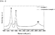
- a peak of 1500 cm -1 or less, or 1100 to 1500 cm -1 derived from the carbon defect structure exhibits an intensity equal to or greater than the peak observed at more than 1500 cm -1 and 2000 cm -1 or less (G band; a peak derived from normal carbon having a graphitic structure). More specifically, the intensity ratio defined as the peak of the D band / the peak of the P band may be 1 or more, or 1 to 1.5. or 1.1 to 1.3.
- an additional broad peak may be confirmed in a region of 2500 cm -1 or more, or 2500 to 2900 cm -1 , or 2600 to 2800 cm -1 . From this, it can be confirmed that the amorphous carbon layer may have a shape including a plurality of carbon layers.
- lithium ions and/or lithium compounds can be two-dimensionally intercalated through the carbon defect structure and nanopores, and the lithium metal electrodeposited around such lithium ions or the like may be two-dimensionally included on the amorphous carbon layer.
- the lithium ions and the like, and the lithium metal may function as a lithium ion source for the negative electrode.
- the amorphous carbon layer includes a high-density lithium ion source that is two-dimensionally formed therein, and can function as an active material layer by itself. Therefore, the all-solid-state battery including the negative electrode of one embodiment can exhibit high capacity and high energy characteristics comparable to or higher than those of an existing lithium metal battery. Furthermore, problems, such as lithium dendrite growing three-dimensionally outside the electrode from the lithium metal thin film formed or the like in the form of a separate thin film can also be fundamentally suppressed, whereby the all-solid-state battery including the negative electrode of one embodiment can exhibit significantly improved life characteristics and safety.
- a solid electrolyte material is contained in the nanopores of the amorphous carbon layer.
- a solid electrolyte may have a large contact area with the negative electrode, furthermore, lithium metal acting as an active material layer, and the like. Therefore, the all-solid-state battery including the negative electrode of one embodiment can exhibit sufficient contact characteristics between the negative electrode and the solid electrolyte, low interfacial resistance, and high ionic conductivity.
- Such a solid electrolyte material may be formed, for example, by coating and drying a slurry composition including a solid electrolyte, a binder and a solvent on the amorphous carbon layer, and as a result, can be impregnated and formed in the nanopores. Further, in the negative electrode finally formed by such a method, the solid electrolyte material present in the nanopores may include a solid electrolyte and a binder.
- the type of the solid electrolyte is not particularly limited, and any solid electrolyte previously known to be usable in an all-solid-state battery, for example, an oxide-based, sulfide-based, or polymer-based solid electrolyte, can be used without particular limitation.
- the sulfide-based solid electrolyte can be appropriately used in consideration of the slurry coating processability and high ionic conductivity of the solid electrolyte material, a sulfide-based solid electrolyte.
- Such a sulfide-based solid electrolyte may include, for example, a sulfide-based compound represented by the following Chemical Formula 1.
- a sulfide-based compound represented by the following Chemical Formula 1 an argyrodite-based compound exhibiting high ionic conductivity and excellent coating processability, for example, a complex compound of Li 2 S-P 2 S 5 , and the like can be preferably used: [Chemical Formula 1] M 1 a M 2 b S c X 1 d in the Chemical Formula 1, M 1 is at least one selected from an alkaline metal and an alkaline earth metal, M 2 is Sb, Sn, Mg, Ba, B, Al, Ga, In, Si, Ge, Pb, N, P, As, Bi, Ti, V, Cr, Mn, Fe, Co, Ni, Cu, Y, Zr, Nb, Mo, Tc, Ru, Rh, Pd, Ag, Hf, Ta, W or La, X 1 is F, Cl, Br, I
- the binder included with the solid electrolyte is a component added in consideration of the slurry coating processability and the adhesiveness of the solid electrolyte to the negative electrode, and any polymer binder previously known to be usable for forming an electrode, such as a positive electrode or a negative electrode can be used without particular limitation.
- Examples of such a polymer binder may include butadiene rubber binders such as an acrylic binder, a polyvinylidene fluoride (PVDF)-based binder, a polytetrafluoroethylene (PTFE)-based binder, or a butadiene rubber-based binder, and it goes without saying that in addition to these, various polymer binders can be used.
- PVDF polyvinylidene fluoride
- PTFE polytetrafluoroethylene
- the negative electrode of the above-mentioned one embodiment as the crystalline carbon layer supporting the amorphous carbon layer is formed from a crystalline carbon fabric, and the like, it includes a plurality of carbon fibers, and may have a thickness of 1 to 50 ⁇ m, or 2 to 30 ⁇ m, or 1 to 10 ⁇ m. Thereby, the negative electrode can exhibit appropriate mechanical and electrochemical characteristics.
- This crystalline carbon layer can function as a kind of negative electrode current collector while supporting the amorphous carbon layer functioning as the active material layer, whereby in the negative electrode of one embodiment, it is also possible to omit a separate metal current collector.
- the negative electrode of one embodiment may include only a crystalline carbon layer functioning as the current collector, an amorphous carbon layer functioning as an active material layer including the lithium ion source described above, and a solid electrolyte material formed in the nanopores of the amorphous carbon layer, but additionally, it can further include a metal current collector such as a copper current collector, a nickel current collector, or a stainless (SUS) current collector for supporting the crystalline carbon layer. Since such an additional metal current collector may follow the configuration of a metal current collector in an electrode of a general all-solid-state battery or lithium secondary battery, an additional description thereof will be omitted.
- a metal current collector such as a copper current collector, a nickel current collector, or a stainless (SUS) current collector for supporting the crystalline carbon layer.
- the negative electrode for an all-solid-state battery as described above can be manufactured by a method comprising the steps of: subjecting a crystalline carbon fabric containing plural carbon fibers to an oxygen plasma treatment to oxidize the surface; reacting the surface-oxidized crystalline carbon fabric, a nitrogen precursor and a metal precursor to form a carbon fabric coated with a metal organic framework (MOF); calcinating and carbonizing the carbon fabric coated with the metal organic framework at a temperature of 700°C or more to form an amorphous carbon layer on the crystalline carbon fabric; and coating and drying a slurry composition containing a solid electrolyte, a binder and a solvent on the amorphous carbon layer.
- MOF metal organic framework
- the method may further include electrochemically reacting the negative electrode or a battery including the same, bonding the lithium ion or lithium carbide compound onto the amorphous carbon layer and electrodepositing a lithium metal around the lithium ion or lithium carbide compound.
- the crystalline carbon fabric corresponding to the crystalline carbon layer can be subjected to an oxygen plasma treatment to oxidize the surface, and the surface-oxidized crystalline carbon fabric, a nitrogen precursor and a metal precursor can be reacted to form a carbon fabric coated with a metal organic framework (MOF). Then, as it is subjected to high-temperature calcination and carbonization to decompose and remove the metal organic framework, a carbon defect structure formed of electron-deficient carbon atoms and an amorphous carbon layer including the same can be formed in the portion where the metal organic framework has been formed.
- MOF metal organic framework
- a solid electrolyte for example, a slurry composition including a sulfide solid electrolyte, a binder and a solvent is coated and dried on the amorphous carbon layer, so that a solid electrolyte material including a solid electrolyte and a binder can be impregnated and formed in the nanopores of the amorphous carbon layer.
- the solid electrolyte material is electrochemically reacted with a negative electrode formed in the nanopores or a battery including the same, the lithium ion or lithium carbide compound is intercalated onto the amorphous carbon layer, and lithium metal is electrodeposited around them.
- the lithium ion source formed two-dimensionally in the amorphous carbon layer, which makes it possible to manufacture the negative electrode of one embodiment exhibiting the above-mentioned excellent characteristics.
- the lithium ion or lithium metal can be two-dimensionally intercalated and formed around the carbon defect structure in the amorphous carbon layer. Therefore, unlike a lithium metal thin film that is three-dimensionally added separately, lithium dendrite growth or the like is not caused therefrom. Further, the lithium metal or the like acts as a lithium ion source for the negative electrode, so that the amorphous carbon layer including the same can function as an active material layer by itself.
- crystalline carbon fabric for example, a carbon paper formed of carbon fibers having a diameter of 1 to 8 ⁇ m, or 3 to 5 ⁇ m can be used, and additionally, any other equivalent crystalline carbon fabric can be used without particular limitation.
- one surface or both surfaces of the crystalline carbon fabric can be surface-treated with oxygen plasma or mixed gas plasma in which an inert gas such as oxygen and argon is mixed, thereby performing surface oxidation, which makes it possible to define the portion where the metal organic framework and the carbon defect structure are formed later.
- the type of the metal organic framework or the type of the nitrogen precursor and the metal precursor for the formation thereof are not particularly limited. This is because, in the manufacturing method of another embodiment, the metal organic framework is carbonized in a subsequent step to remove all remaining metals and organic components except carbon, and the carbon component also contributes only to the formation of a carbon defect structure.
- a specific example of the metal organic framework that can be formed in the above step may include at least one compound selected from the group consisting of Zn 2 DOT (MOF-74), Cu 2 (BDC-Br) 2 (H 2 O) 2 (MOF-101), Zn 4 O(BTB) 2 (MOF-177), [Fe 3 O(BDC) 3 (DMF) 3 ][FeCl 4 ].(DMF) 3 (MOF-235), Al(OH)(BPYDC) (MOF-253), Zn 4 O(BDC) 3 . 7DEF.3H 2 O (IRMOF-1 (MOF-5)), Zn 4 O(TPDC) 3 .
- a metal organic framework in the form of a metal zeolite-imidazole structure such as ZIF-8 can be preferably formed.
- a nitrogen precursor and a metal precursor corresponding thereto can appropriately select and use according to the type of the metal organic frameworks.
- an imidazole-based compound such as methyl imidazole can be preferably used as a nitrogen precursor, and in addition to these, various nitrogen precursors can be selected and used according to the type of the above-mentioned metal organic frameworks.
- the metal precursor examples include at least one metal-containing compound selected from the group consisting of zinc (Zn), aluminum (Al), copper (Cu), zirconium (Zr), iron (Fe), chromium (Cr), and gadolinium (Gd), and various salts, such as nitrates, hydroxides, or sulfates of these metals, or compounds in the form of hydrates and/or solvates thereof can be used without particular limitation.
- the surface-oxidized crystalline carbon fabric, the nitrogen precursor, and the metal precursor can be reacted in a polar organic solvent such as water or methanol under stirring, and after the reaction, washing and drying steps using a polar organic solvent can also be further performed. Specific progress conditions of these washing and drying steps are specifically described in Examples described later.
- the carbon fabric after forming the carbon fabric coated with the metal organic framework, the carbon fabric can be calcinated and carbonized at a temperature of 700 °C or more, or 700 to 1300°C, or 800 to 1200°C.
- the metal organic framework is carbonized, decomposed and removed, and an amorphous carbon layer containing the carbon defect structure described above can be formed.
- an inorganic impurity removal step using hydrochloric acid, a washing step, and a drying step may be further performed.
- a step of coating the slurry composition containing the solid electrolyte, the binder, and the solvent on the amorphous carbon layer and selectively drying it can be performed.
- the coating step can be performed by a method of bar coating or dip coating.
- the negative electrode is electrochemically reacted, and a lithium ion or a lithium carbide compound is bonded and intercalated onto the amorphous carbon layer, and by using lithium ions or the like as a nucleus, the lithium metal can be electrodeposited around them.
- This electrochemical reaction may proceed as a separate lithium ion intercalation reaction or lithium metal electrodeposition reaction during the manufacture of the negative electrode, but the reaction may be replaced by the progress of the initial charge/discharge step after the manufacture of the lithium secondary battery.
- the lithium ions or lithium carbide compounds are bonded by an electrochemical reaction that occurs naturally during the process of the initial charge/discharge step, and intercalation of lithium ions and the like may occur therefrom.
- an all-solid-state battery including the above-mentioned negative electrode is provided.
- the all-solid-state battery of another embodiment may include a positive electrode containing a positive electrode current collector and a lithium composite oxide-based positive electrode active material layer formed on the positive electrode current collector; and the negative electrode of one embodiment described above, and further include an additional solid electrolyte layer interposed between the positive electrode and the negative electrode.
- the all-solid-state battery of another embodiment including the negative electrode of the one embodiment described above can exhibit improved life characteristics and safety by fundamentally suppressing the growth of lithium dendrites, while exhibiting high energy density and high capacity characteristics comparable to batteries using existing lithium metal negative electrode.
- the solid electrolyte material is uniformly formed in the nanopores, and thus, sufficient contact characteristics between the negative electrode and the solid electrolyte, low interfacial resistance, and excellent ionic conductivity can be ensured.
- an additional solid electrolyte layer may be further included between the positive electrode and the negative electrode.
- Such solid electrolyte layer may include the solid electrolyte and binder identical to or different from the solid electrolyte material contained in the nanopores of the negative electrode.
- such solid electrolyte layer can be formed by coating a slurry composition containing the solid electrolyte, a binder and a solvent onto the electrode of the positive electrode or the negative electrode, or by coating and drying the slurry composition onto a separate release paper to form a solid electrolyte layer and then laminating it on the electrode, or by impregnating the solid electrolyte into a porous nonwoven fabric.
- a slurry composition containing the solid electrolyte, a binder and a solvent onto the electrode of the positive electrode or the negative electrode
- coating and drying the slurry composition onto a separate release paper to form a solid electrolyte layer and then laminating it on the electrode, or by impregnating the solid electrolyte into a porous nonwoven fabric.
- the composition and formation method of the additional solid electrolyte layer may follow the composition and formation method of the solid electrolyte layer of the all-solid-state battery conventionally known in the art, an additional description thereof will be omitted.
- the remaining components such as the positive electrode excluding the negative electrode and the solid electrolyte layer can follow the configuration of a conventional all-solid-state battery.
- a positive electrode may include a positive electrode current collector and a positive electrode active material layer disposed on the positive electrode current collector.
- the positive electrode is manufactured by mixing an active material and a binder, optionally, the above-mentioned solid electrolyte, for example, the same sulfide solid electrolyte as those contained in the negative electrode or additional solid electrolyte layer, a conductive material, a filler, and the like in a solvent to prepare an electrode mixture slurry, and then coating this electrode mixture slurry onto each positive electrode current collector.
- the solid electrolyte and the binder are the same as those described above with respect to the negative electrode, and the like, and the remaining positive electrode manufacturing methods are widely known in the art, and thus, a detailed description thereof will be omitted herein.
- the positive electrode active material it is not particularly limited as long as it is a lithium composite oxide-based material capable of reversibly intercalating and de-intercalating lithium ions.
- it may include one or more of complex oxides of cobalt, manganese, nickel, iron, or a combination of metals; and lithium.
- a compound represented by any of the following chemical formulas can be used as the positive electrode active material: Li a A 1-b R b D 2 (wherein 0.90 ⁇ a ⁇ 1.8 and 0 ⁇ b ⁇ 0.5); Li a E 1-b R b O 2-c D c (wherein 0.90 ⁇ a ⁇ 1.8, 0 ⁇ b ⁇ 0.5, and 0 ⁇ c ⁇ 0.05); LiE 2-b R b O 4-c D c (wherein 0 ⁇ b ⁇ 0.5, 0 ⁇ c ⁇ 0.05); Li a Ni 1-b-c Co b R c D ⁇ (wherein 0.90 ⁇ a ⁇ 1.8, 0 ⁇ b ⁇ 0.5, 0 ⁇ c ⁇ 0.05 and 0 ⁇ ⁇ ⁇ 2); Li a Ni 1-b-c Co b R c O 2- ⁇ Z ⁇ (wherein 0.90 ⁇ a ⁇ 1.8, 0 ⁇ b ⁇
- A is Ni, Co, Mn or a combination thereof;
- R is Al, Ni, Co, Mn, Cr, Fe, Mg, Sr, V, a rare earth element or a combination thereof;
- D is O, F, S, P or a combination thereof;
- E is Co, Mn or a combination thereof;
- Z is F, S, P or a combination thereof;
- G is Al, Cr, Mn, Fe, Mg, La, Ce, Sr, V or a combination thereof;
- Q is Ti, Mo, Mn or a combination thereof;
- the coating layer may include a coating element compound such as coating element oxide, hydroxide, coating element oxyhydroxide, coating element oxycarbonate or coating element hydroxycarbonate .
- the compounds forming these coating layers may be amorphous or crystalline.
- As a coating element included in the coating layer Mg, Al, Co, K, Na, Ca, Si, Ti, V, Sn, Ge, Ga, B, As, Zr or a mixture thereof can be used.
- any coating method can be used as long as it can be coated by a method (e.g., spray coating or dipping method, etc.) that does not adversely affect the physical properties of the positive electrode active material by using these elements in the compound. Since this is a content that can be widely understood by those worked in the art, and thus, detailed descriptions thereof will be omitted.
- the positive electrode current collector is typically fabricated to a thickness of 3 to 500 ⁇ m.
- the positive electrode current collector is not particularly limited as long as a corresponding battery has high conductivity without causing a chemical change in the battery, and for example, may be formed of stainless steel, aluminum, nickel, titanium, baked carbon, or a material formed by surface-treating a surface of stainless steel or aluminum with carbon, nickel, titanium, silver, or the like.
- the current collector may have fine protrusions and depressions formed on a surface thereof to enhance adherence of a positive electrode active material, and may be formed in various forms such as a film, a sheet, a foil, a net, a porous body, a foaming body, and a non-woven fabric structure.
- the conductive material is not particularly limited as long as a corresponding battery has high conductivity without causing a chemical change in the battery, and for example, graphite such as natural graphite and artificial graphite; carbon blacks such as carbon black, acetylene black, ketjen black, channel black, furnace black, lamp black, and thermal black; conductive fibers such as carbon fiber and metal fiber; metal powders such as carbon fluoride powder, aluminum powder, and nickel powder; conductive whisker such as zinc oxide and potassium titanate; conductive metal oxides such as titanium oxide; conductive materials such as polyphenylene derivatives can be used.
- graphite such as natural graphite and artificial graphite
- carbon blacks such as carbon black, acetylene black, ketjen black, channel black, furnace black, lamp black, and thermal black
- conductive fibers such as carbon fiber and metal fiber
- metal powders such as carbon fluoride powder, aluminum powder, and nickel powder
- conductive whisker such as zinc oxide and potassium titanate
- the all-solid-state battery of the one embodiment may not only be used in a unit cell used as a power source for a small device, but also it can be used as a unit cell in a medium or large-sized battery module including a plurality of battery cells. Furthermore, a battery pack including the battery module may be configured.
- Example 1 Manufacture of negative electrode for all-solid-state battery
- Carbon paper (HCP010N, Shanghai Hesen Electric Co. Ltd. USA) was purchased, and both front and back surfaces of the carbon paper were surface-oxidized using oxygen plasma treatment.
- the plasma treatment was carried out by a method of treating the plasma on the front surface and the back surface for 15 minutes, respectively, while flowing a mixed gas of oxygen and argon gas.
- the surface-oxidized carbon paper was placed in 100 ml of methanol in which 2-methyl imidazole (13.136 g, 8 eq) was dissolved, and the mixture was stirred for 6 hours. Then, 100 mL of methanol in which zinc nitrate hexahydrate (5.95 g, 1 eq) was dissolved was added to the solution, and then the mixture was stirred for 12 hours. Thereby, a carbon paper coated with a zinc-organic framework (ZLF-8) was formed.
- ZLF-8 zinc-organic framework
- the carbon paper was kept and dried for 12 hours, in an oven at a temperature of about 80°C and in a vacuum state.
- the process up to the drying was set to once, and the zinc-organozinc framework coating was repeated twice in total.
- the carbon paper was heated up to 1000°C at a temperature rising rate of 5°C min -1 , and then calcinated and carbonized in a nitrogen atmosphere for 5 hours.
- the carbonized carbon paper was stirred in a 2 M hydrochloric acid solution for 6 hours to remove impurity minerals (Zn).
- the carbon paper was taken out of hydrochloric acid, immersed in deionized water (DI), washed three times for 20 minutes each, and then finally dried in a vacuum oven at 70°C for 7 hours. According to the above-mentioned process, an amorphous carbon layer was formed on the crystalline carbon layer of the carbon paper.
- Li 2 S-P 2 S 5 as a sulfide solid electrolyte and NBR as a binder were added to anisole in a weight ratio of 95:5 to prepare a slurry composition (solid content: 60 wt.%) for forming a solid electrolyte material.
- This slurry composition was mixed and formed in a Thinky mixer at a speed of 2000 rpm for 1 minute.
- the slurry composition was bar-coated onto the amorphous carbon layer, and dried overnight at room temperature/atmospheric pressure, so that a solid electrolyte material was formed on the amorphous carbon layer.
- Example 2 Manufacture of an all-solid-state battery including the negative electrode of Example 1
- a positive electrode and an additional solid electrolyte layer were prepared by the following method.
- LiNi 0.8 Co 0.1 Mn 0.1 O 2 as a positive electrode active material Li 2 S-P 2 S 5 as a sulfide solid electrolyte, NBR as a binder, and VGCF as a conductive material were added to anisole in a weight ratio of 75.5:22.1:1.5:1 to prepare a slurry composition (solid content 70 wt.%) for forming a positive electrode active material layer. This was coated onto one surface of an aluminum thin film (thickness: about 10 ⁇ m) and dried at 60°C for 6 hours to prepare a positive electrode.
- Li 2 S-P 2 S 5 as a sulfide solid electrolyte, and NBR as a binder were added to anisole in a weight ratio of 95:5 to prepare a slurry composition (solid content: 60 wt.%) for forming a solid electrolyte layer.
- This slurry composition was mixed and formed in a Thinky mixer at a speed of 2000 rpm for 1 minute.
- the slurry composition coated onto one surface of a release paper made of polyethylene terephthalate, and dried overnight at room temperature and atmospheric pressure conditions and the release paper was removed to prepare a solid electrolyte layer. At this time, the thickness of the solid electrolyte layer was 30 ⁇ m.
- the positive electrode and the solid electrolyte layer were laminated and pressurized at a pressure of 500 MPa for 5 minutes to prepare a laminate of the positive electrode and the solid electrolyte layer.
- the porosity of the positive electrode was 15 vol%
- the porosity of the solid electrolyte layer was 5 vol%.
- Example 2 the laminate and the negative electrode prepared in Example 1 were sequentially laminated and pressed at 200 MPa for 5 minutes to obtain an electrode assembly.
- the pressing was performed using a CIP (cold isotatic pressing) apparatus.
- CIP cold isotatic pressing
- the slurry composition having the same composition as that of Example 1 was coated onto the carbon paper used as the first raw material in Example 1 by the same method to form a solid electrolyte material.
- An all-solid-state battery containing the negative electrode of Comparative Example 1 instead of the negative electrode of Example 1 was manufactured by the same method as in Example 2, which was used as the all-solid-state battery of Comparative Example 2.
- the electrochemical reaction with the negative electrode was replaced by the charge/discharge process after the battery was manufactured.
- a lithium metal thin film formed to a thickness of 20 um was used as the negative electrode.
- the negative electrode was prepared in a state in which a lithium metal thin film having a thickness of 20 ⁇ m was attached to the surface of a nickel current collector having a thickness of 10 ⁇ m.
- a positive electrode, a solid electrolyte layer, and an all-solid-state battery were sequentially manufactured by the following method.
- the positive electrode was formed in the same manner as in Example 2.
- Li 2 S-P 2 S 5 as a sulfide solid electrolyte and NBR as a binder were added to anisole in a weight ratio of 95:5 to prepare a slurry composition (solid content 60 wt.%) for forming a solid electrolyte layer.
- This slurry composition was mixed and formed in a Thinky mixer at a speed of 2000 rpm for 1 minute.
- the slurry composition coated onto one surface of a release paper made of polyethylene terephthalate, and dried overnight at room temperature and atmospheric pressure conditions and the release paper was removed to prepare a first solid electrolyte layer.
- a separate second solid electrolyte layer was prepared in the same manner as the first solid electrolyte layer. At this time, the thickness of each solid electrolyte layer was 30 ⁇ m.
- the positive electrode and the first solid electrolyte layer were laminated and pressed at a pressure of 500 MPa for 5 minutes to prepare a laminate of the positive electrode and the first solid electrolyte layer.
- a second solid electrolyte layer was further laminated on the above laminate and pressed at a pressure of 500 MPa for 5 minutes to prepare a laminate of the positive electrode and the first and second solid electrolyte layers.
- the laminate and the negative electrode including the lithium metal thin film were sequentially laminated and pressed at 200 MPa for 5 minutes to obtain an electrode assembly.
- the pressing was performed using a CIP (cold isotatic pressing) apparatus.
- CIP cold isotatic pressing
- the carbon layer included in the negative electrode of Comparative Example 1 is an electrode in which carbon fibers having a diameter of 3 ⁇ 5 um were aggregated.
- the negative electrode of Example 1 was formed of a network-shaped defective carbon layer on the fiber surface of the crystalline carbon layer.
- the carbon paper and negative electrode were subjected to elemental analysis with EDS for each manufacturing step of Example 1, and the analysis results are shown in Figs. 2a to 2c along with their corresponding SEM images.
- the element content for each manufacturing step based on the analysis results is summarized in Table 1 below.
- ZLF-8 zinc-organic framework
- Example 1 the characteristics of the negative electrode finally formed in Example 1 depend only on the formation of a carbon defect structure, and not on the zinc-organic framework.
- each carbon layer was analyzed by XPS, and the analysis results are shown in Fig. 3 .
- Fig. 3 it was confirmed that in Example 1, due to the process in which a zinc-organic framework was formed and coated, and then carbonized and removed, a large number of nanopores (vacancies) were formed on the carbon layer.
- Example 1 a carbon defect structure including electron-deficient carbon atoms, particularly, a separate peak (non-conjugated C peak) derived from the nanopores was confirmed.
- the analysis result of Example 1 showed that the intensity ratio of a separate peak derived from such a carbon defect structure / a peak derived from a carbon having a sp2 orbital hybridization structure (normal carbon having no electron deficiency state) is 0.403, which appears strong as compared with Comparative Example 1 in which this intensity ratio is 0.175.
- a peak of 1100 to 1500 cm -1 derived from the carbon defect structure shows an intensity greater than or equal to the peak (G band; peak derived from normal carbon having a graphitic structure) observed at more than 1500 cm -1 and less than 2000 cm -1 , and their intensity ratio, defined as I D /I G ratio, is as high as 1.124.
- the intensity ratio of the peak defined by the I D /I G ratio is as low as 0.788.
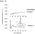
- Example 1 and Comparative Example 1 were subjected to BET analysis, and the results are shown in Fig. 5 . More specifically, BET pore analysis was performed using nitrogen adsorption. Referring to Fig. 5 , it can be confirmed that in the carbon layer of Comparative Example 1, pores between 20 ⁇ 120 nm are developed, and that in the electrode of Example 1, nanopores having a size of about 1.1 nm are mainly developed. It was confirmed that the nanopores of Example 1 correspond to the high-density carbon defect structure confirmed from the XPS and Raman spectrum analysis results.
- Example 1 and Comparative Example 1 the surface of the negative electrode after forming the solid electrolyte material was analyzed by SEM and shown in Figs. 6a to 6d . More specifically, Fig. 6a is a SEM photograph of the front surface of the negative electrode after forming the solid electrolyte material in Example 1, Figs. 6b and 6c are SEM pictures of the rear surface of such a negative electrode. Further, Fig. 6d is an SEM photograph of the rear surface of the negative electrode after forming the solid electrolyte material in Comparative Example 1.
- an all-solid-state battery having a capacity of 20.8 mAh was manufactured by the methods of the Examples and Comparative Examples, charged in CC-CV mode at 4.25V (0.05C cut off) 0.1C, and discharged to 3V at 0.1C to perform a charge/discharge test and electrochemical reaction. This charge/discharge test cycle was repeated, and the capacity retention rate of the discharge capacity was measured.
- the battery of Comparative Example 2 was not only inferior in capacity retention rate and life characteristic to that of Example 2, but also had a short circuit during the evaluation of the life characteristics, and the evaluation of the life characteristic was stopped at a time point of about 35 cycles.
- the battery of Comparative Example 3 exhibited a life characteristic significantly inferior to that of Examples due to the growth of lithium dendrites in the negative electrode and the like.
Landscapes
- Chemical & Material Sciences (AREA)
- Chemical Kinetics & Catalysis (AREA)
- Electrochemistry (AREA)
- General Chemical & Material Sciences (AREA)
- Engineering & Computer Science (AREA)
- Inorganic Chemistry (AREA)
- Manufacturing & Machinery (AREA)
- Materials Engineering (AREA)
- Physics & Mathematics (AREA)
- Condensed Matter Physics & Semiconductors (AREA)
- General Physics & Mathematics (AREA)
- Composite Materials (AREA)
- Battery Electrode And Active Subsutance (AREA)
- Secondary Cells (AREA)
Applications Claiming Priority (2)
| Application Number | Priority Date | Filing Date | Title |
|---|---|---|---|
| KR1020200149184A KR102890757B1 (ko) | 2020-11-10 | 2020-11-10 | 전고체 전지용 음극 및 이를 포함하는 전고체 전지 |
| PCT/KR2021/014241 WO2022102994A1 (ko) | 2020-11-10 | 2021-10-14 | 전고체 전지용 음극 및 이를 포함하는 전고체 전지 |
Publications (2)
| Publication Number | Publication Date |
|---|---|
| EP4084126A1 true EP4084126A1 (de) | 2022-11-02 |
| EP4084126A4 EP4084126A4 (de) | 2023-11-08 |
Family
ID=81601381
Family Applications (1)
| Application Number | Title | Priority Date | Filing Date |
|---|---|---|---|
| EP21892164.1A Pending EP4084126A4 (de) | 2020-11-10 | 2021-10-14 | Anode für festkörperbatterie sowie festkörperbatterie damit |
Country Status (6)
| Country | Link |
|---|---|
| US (1) | US20230065906A1 (de) |
| EP (1) | EP4084126A4 (de) |
| JP (1) | JP7441449B2 (de) |
| KR (1) | KR102890757B1 (de) |
| CN (2) | CN119252860A (de) |
| WO (1) | WO2022102994A1 (de) |
Cited By (1)
| Publication number | Priority date | Publication date | Assignee | Title |
|---|---|---|---|---|
| WO2024154773A1 (ja) * | 2023-01-18 | 2024-07-25 | ダイキン工業株式会社 | テトラフルオロエチレン系ポリマー組成物、電気化学デバイス用バインダー、電極合剤、電極、及び、二次電池 |
Families Citing this family (6)
| Publication number | Priority date | Publication date | Assignee | Title |
|---|---|---|---|---|
| US12525612B2 (en) * | 2020-07-23 | 2026-01-13 | Lg Energy Solution, Ltd. | Negative electrode for lithium secondary battery, method for manufacturing the same, and lithium secondary battery including the same |
| CN115395077A (zh) * | 2022-09-13 | 2022-11-25 | 惠州亿纬锂能股份有限公司 | 一种固态电解质-电极复合体及其制备方法和用途 |
| CN116404125B (zh) * | 2023-03-06 | 2025-07-04 | 合肥国轩电池材料有限公司 | 一种碳-氮化合物包覆三元正极材料及其制备方法 |
| KR20240159311A (ko) * | 2023-04-28 | 2024-11-05 | 고려대학교 산학협력단 | 리튬이차전지용 음극 및 이의 제조 방법 |
| KR102913295B1 (ko) | 2023-11-06 | 2026-01-16 | 한국전자기술연구원 | 금속 제올라이트-이미다졸 구조체가 첨가된 고체전해질 및 그를 포함하는 전고체전지 |
| CN119518116A (zh) * | 2025-01-21 | 2025-02-25 | 中南大学 | 一种基于无定型玻璃态金属有机框架材料的固态电解质及其制备方法和应用 |
Family Cites Families (27)
| Publication number | Priority date | Publication date | Assignee | Title |
|---|---|---|---|---|
| JP5708467B2 (ja) | 2011-03-18 | 2015-04-30 | トヨタ自動車株式会社 | スラリー、固体電解質層の製造方法、電極活物質層の製造方法、および全固体電池の製造方法 |
| US8951675B2 (en) * | 2011-10-13 | 2015-02-10 | Apple Inc. | Graphene current collectors in batteries for portable electronic devices |
| US20150056520A1 (en) * | 2012-03-01 | 2015-02-26 | Johnson Ip Holding, Llc | Impregnated sintered solid state composite electrode, solid state battery, and methods of preparation |
| JP2013219023A (ja) | 2012-03-16 | 2013-10-24 | Sumitomo Bakelite Co Ltd | リチウムイオン二次電池用炭素材、リチウムイオン二次電池用負極材およびリチウムイオン二次電池 |
| JPWO2013140942A1 (ja) * | 2012-03-22 | 2015-08-03 | 住友電気工業株式会社 | 全固体リチウム二次電池 |
| KR20160033482A (ko) * | 2014-09-18 | 2016-03-28 | 주식회사 엘지화학 | 전극 제조방법, 이에 의해 제조된 전극 및 이를 포함하는 이차전지 |
| KR101763478B1 (ko) * | 2014-10-02 | 2017-07-31 | 주식회사 엘지화학 | 리튬 이차전지용 음극활물질, 이의 제조방법, 및 이를 포함하는 리튬 이차전지 |
| KR102221799B1 (ko) * | 2014-10-22 | 2021-03-02 | 삼성에스디아이 주식회사 | 리튬 이차 전지 |
| KR102293297B1 (ko) * | 2015-07-27 | 2021-08-23 | 한국전기연구원 | 전고체 전지 및 이의 제조방법 |
| US11145851B2 (en) * | 2015-11-11 | 2021-10-12 | The Board Of Trustees Of The Leland Stanford Junior University | Composite lithium metal anodes for lithium batteries with reduced volumetric fluctuation during cycling and dendrite suppression |
| US10497968B2 (en) * | 2016-01-04 | 2019-12-03 | Global Graphene Group, Inc. | Solid state electrolyte for lithium secondary battery |
| SG11201805804SA (en) * | 2016-01-14 | 2018-08-30 | Agency Science Tech & Res | Free-standing mof-derived hybrid porous carbon nanofiber mats |
| JP2016146365A (ja) * | 2016-05-18 | 2016-08-12 | 出光興産株式会社 | 電極材料、及びそれを用いたリチウムイオン電池 |
| KR102090285B1 (ko) * | 2016-12-22 | 2020-03-17 | 울산과학기술원 | 전고체전지의 전극, 이의 제조 방법, 및 이를 포함하는 전고체전지 |
| JPWO2018168505A1 (ja) * | 2017-03-14 | 2019-12-12 | 富士フイルム株式会社 | 固体電解質組成物、固体電解質含有シートおよび全固体二次電池、並びに、固体電解質組成物、固体電解質含有シートおよび全固体二次電池の製造方法 |
| KR101906043B1 (ko) * | 2017-03-24 | 2018-11-30 | 연세대학교 산학협력단 | 마이크로파를 이용한 탄소-금속유기골격구조(MOFs) 복합체 제조 방법 |
| JP6927102B2 (ja) | 2018-03-16 | 2021-08-25 | トヨタ自動車株式会社 | リチウム金属二次電池 |
| CN111448702A (zh) * | 2018-09-04 | 2020-07-24 | 三井金属矿业株式会社 | 硫化物系化合物颗粒、固体电解质和锂二次电池 |
| CN109411756A (zh) * | 2018-09-21 | 2019-03-01 | 中国科学院物理研究所 | 一种二次电池碳三维结构电极及其制备方法和应用 |
| KR102681364B1 (ko) * | 2018-12-12 | 2024-07-03 | 현대자동차주식회사 | 활물질층이 없는 전고체 전지의 음극 및 이의 제조방법 |
| KR20200075250A (ko) * | 2018-12-18 | 2020-06-26 | 현대자동차주식회사 | 알칼리 토금속이 도핑된 황화물계 고체전해질 및 이의 제조방법 |
| CN109786669B (zh) * | 2019-01-04 | 2021-12-21 | 蜂巢能源科技有限公司 | 锂硫电池及其制备方法 |
| CN109980235B (zh) * | 2019-04-08 | 2021-01-26 | 中国科学院化学研究所 | 一种低体积变化的金属二次电池负极制备方法及应用 |
| CN112310465B (zh) * | 2019-07-29 | 2024-01-30 | 通用汽车环球科技运作有限责任公司 | 硫化物浸渍的固态电池的制造方法 |
| CN111082050A (zh) * | 2019-12-20 | 2020-04-28 | 兰州大学 | 一种锂离子电池负极材料及其制备方法 |
| WO2021200588A1 (ja) * | 2020-03-31 | 2021-10-07 | 日東電工株式会社 | 蓄電デバイス用負極、蓄電デバイス用複合粒子、及び蓄電デバイス |
| US12525612B2 (en) * | 2020-07-23 | 2026-01-13 | Lg Energy Solution, Ltd. | Negative electrode for lithium secondary battery, method for manufacturing the same, and lithium secondary battery including the same |
-
2020
- 2020-11-10 KR KR1020200149184A patent/KR102890757B1/ko active Active
-
2021
- 2021-10-14 WO PCT/KR2021/014241 patent/WO2022102994A1/ko not_active Ceased
- 2021-10-14 JP JP2022546534A patent/JP7441449B2/ja active Active
- 2021-10-14 CN CN202411561095.4A patent/CN119252860A/zh active Pending
- 2021-10-14 EP EP21892164.1A patent/EP4084126A4/de active Pending
- 2021-10-14 US US17/792,366 patent/US20230065906A1/en active Pending
- 2021-10-14 CN CN202180008524.3A patent/CN114930572B/zh active Active
Cited By (2)
| Publication number | Priority date | Publication date | Assignee | Title |
|---|---|---|---|---|
| WO2024154773A1 (ja) * | 2023-01-18 | 2024-07-25 | ダイキン工業株式会社 | テトラフルオロエチレン系ポリマー組成物、電気化学デバイス用バインダー、電極合剤、電極、及び、二次電池 |
| JP2024102026A (ja) * | 2023-01-18 | 2024-07-30 | ダイキン工業株式会社 | テトラフルオロエチレン系ポリマー組成物、電気化学デバイス用バインダー、電極合剤、電極、及び、二次電池 |
Also Published As
| Publication number | Publication date |
|---|---|
| WO2022102994A1 (ko) | 2022-05-19 |
| KR102890757B1 (ko) | 2025-11-24 |
| JP2023513070A (ja) | 2023-03-30 |
| EP4084126A4 (de) | 2023-11-08 |
| US20230065906A1 (en) | 2023-03-02 |
| CN114930572B (zh) | 2024-11-22 |
| KR20220063392A (ko) | 2022-05-17 |
| CN119252860A (zh) | 2025-01-03 |
| CN114930572A (zh) | 2022-08-19 |
| JP7441449B2 (ja) | 2024-03-01 |
Similar Documents
| Publication | Publication Date | Title |
|---|---|---|
| EP4084126A1 (de) | Anode für festkörperbatterie sowie festkörperbatterie damit | |
| KR102207927B1 (ko) | 전해질, 상기 전해질을 포함하는 리튬전지 및 리튬금속전지, 및 상기 전해질의 제조방법 | |
| CN110880616A (zh) | 固体电解质、其制备方法和包括其的二次电池 | |
| KR20150101310A (ko) | 음극 활물질, 이를 포함하는 리튬 전지, 및 이의 제조방법 | |
| JP2015503189A (ja) | 水性電解液リチウム硫黄電池 | |
| KR102156796B1 (ko) | 탄소 코팅 형성 방법 | |
| KR20150062123A (ko) | 양극 활물질, 이를 포함하는 이차전지, 및 이의 제조방법 | |
| KR101097244B1 (ko) | 리튬 전지용 음극 및 이를 구비한 리튬 전지 | |
| KR20150045337A (ko) | 양극 활물질, 그 제조방법 및 이를 포함한 양극을 구비한 리튬 전지 | |
| JP7575572B2 (ja) | 全固体電池用の負極集電体及びそれを含む全固体電池用の負極 | |
| KR101599693B1 (ko) | 리튬 공기 전지 정극용 탄소 재료 및 리튬 공기 전지 | |
| CN110945704A (zh) | 二次电池用电解质和包含所述电解质的二次电池 | |
| US12347827B2 (en) | Bilayer component for a lithium battery | |
| KR101696902B1 (ko) | 활물질, 그 제조방법, 이를 포함하는 전극 및 이를 포함한 이차 전지 | |
| KR101584114B1 (ko) | 금속이 코팅된 전극 활물질의 전구체 및 그의 제조방법 | |
| KR102872591B1 (ko) | 리튬 이차 전지용 음극, 이의 제조 방법, 및 이를 포함하는 리튬 이차 전지 | |
| US12525612B2 (en) | Negative electrode for lithium secondary battery, method for manufacturing the same, and lithium secondary battery including the same | |
| KR102872592B1 (ko) | 리튬 이차 전지용 음극 및 이를 포함하는 리튬 이차 전지 | |
| Ku et al. | Tailoring lithium horizontal deposition for long-lasting high-loading NCA (≥ 5 mA h cm–2)|| lithium–metal full cells in carbonate electrolytes | |
| Pathak | Lithium-ion battery and beyond: oxygen vacancy creation in tungsten trioxide and surface modification of lithium metal | |
| EP4525072A1 (de) | Unterbaugruppe für festkörperbatterie, festkörperbatterie und verfahren zur herstellung einer festkörperbatterie | |
| JP2021068534A (ja) | LiBF4を含有する電解液及びリチウムイオン二次電池 | |
| JP2020135989A (ja) | 電解液及び二次電池 | |
| Libich et al. | Lithiated graphite materials for negative electrodes of lithium-ion batteries | |
| JP2020177814A (ja) | 電解液及び二次電池 |
Legal Events
| Date | Code | Title | Description |
|---|---|---|---|
| STAA | Information on the status of an ep patent application or granted ep patent |
Free format text: STATUS: THE INTERNATIONAL PUBLICATION HAS BEEN MADE |
|
| PUAI | Public reference made under article 153(3) epc to a published international application that has entered the european phase |
Free format text: ORIGINAL CODE: 0009012 |
|
| STAA | Information on the status of an ep patent application or granted ep patent |
Free format text: STATUS: REQUEST FOR EXAMINATION WAS MADE |
|
| 17P | Request for examination filed |
Effective date: 20220726 |
|
| AK | Designated contracting states |
Kind code of ref document: A1 Designated state(s): AL AT BE BG CH CY CZ DE DK EE ES FI FR GB GR HR HU IE IS IT LI LT LU LV MC MK MT NL NO PL PT RO RS SE SI SK SM TR |
|
| A4 | Supplementary search report drawn up and despatched |
Effective date: 20231006 |
|
| RIC1 | Information provided on ipc code assigned before grant |
Ipc: H01M 4/36 20060101ALI20230929BHEP Ipc: H01M 4/04 20060101ALI20230929BHEP Ipc: H01M 4/02 20060101ALI20230929BHEP Ipc: H01M 10/0525 20100101ALI20230929BHEP Ipc: H01M 10/0562 20100101ALI20230929BHEP Ipc: H01M 4/62 20060101ALI20230929BHEP Ipc: H01M 4/587 20100101ALI20230929BHEP Ipc: H01M 4/583 20100101ALI20230929BHEP Ipc: H01M 4/133 20100101AFI20230929BHEP |
|
| DAV | Request for validation of the european patent (deleted) | ||
| DAX | Request for extension of the european patent (deleted) | ||
| STAA | Information on the status of an ep patent application or granted ep patent |
Free format text: STATUS: EXAMINATION IS IN PROGRESS |
|
| 17Q | First examination report despatched |
Effective date: 20250114 |