EP4083398B1 - Verfahren zum bestimmen einer partikelbeladung eines partikelfilters, insbesondere zum einsatz in einer abgasnachbehandlungseinrichtung für einen verbrennungsmotor - Google Patents
Verfahren zum bestimmen einer partikelbeladung eines partikelfilters, insbesondere zum einsatz in einer abgasnachbehandlungseinrichtung für einen verbrennungsmotor Download PDFInfo
- Publication number
- EP4083398B1 EP4083398B1 EP21170347.5A EP21170347A EP4083398B1 EP 4083398 B1 EP4083398 B1 EP 4083398B1 EP 21170347 A EP21170347 A EP 21170347A EP 4083398 B1 EP4083398 B1 EP 4083398B1
- Authority
- EP
- European Patent Office
- Prior art keywords
- soot
- mod
- wall
- layer
- modelled
- Prior art date
- Legal status (The legal status is an assumption and is not a legal conclusion. Google has not performed a legal analysis and makes no representation as to the accuracy of the status listed.)
- Active
Links
Images

Classifications
-
- F—MECHANICAL ENGINEERING; LIGHTING; HEATING; WEAPONS; BLASTING
- F01—MACHINES OR ENGINES IN GENERAL; ENGINE PLANTS IN GENERAL; STEAM ENGINES
- F01N—GAS-FLOW SILENCERS OR EXHAUST APPARATUS FOR MACHINES OR ENGINES IN GENERAL; GAS-FLOW SILENCERS OR EXHAUST APPARATUS FOR INTERNAL-COMBUSTION ENGINES
- F01N9/00—Electrical control of exhaust gas treating apparatus
- F01N9/002—Electrical control of exhaust gas treating apparatus of filter regeneration
-
- F—MECHANICAL ENGINEERING; LIGHTING; HEATING; WEAPONS; BLASTING
- F01—MACHINES OR ENGINES IN GENERAL; ENGINE PLANTS IN GENERAL; STEAM ENGINES
- F01N—GAS-FLOW SILENCERS OR EXHAUST APPARATUS FOR MACHINES OR ENGINES IN GENERAL; GAS-FLOW SILENCERS OR EXHAUST APPARATUS FOR INTERNAL-COMBUSTION ENGINES
- F01N11/00—Monitoring or diagnostic devices for exhaust-gas treatment apparatus
- F01N11/002—Monitoring or diagnostic devices for exhaust-gas treatment apparatus the diagnostic devices measuring or estimating temperature or pressure in, or downstream of the exhaust apparatus
-
- F—MECHANICAL ENGINEERING; LIGHTING; HEATING; WEAPONS; BLASTING
- F01—MACHINES OR ENGINES IN GENERAL; ENGINE PLANTS IN GENERAL; STEAM ENGINES
- F01N—GAS-FLOW SILENCERS OR EXHAUST APPARATUS FOR MACHINES OR ENGINES IN GENERAL; GAS-FLOW SILENCERS OR EXHAUST APPARATUS FOR INTERNAL-COMBUSTION ENGINES
- F01N3/00—Exhaust or silencing apparatus having means for purifying, rendering innocuous, or otherwise treating exhaust
- F01N3/02—Exhaust or silencing apparatus having means for purifying, rendering innocuous, or otherwise treating exhaust for cooling, or for removing solid constituents of, exhaust
- F01N3/021—Exhaust or silencing apparatus having means for purifying, rendering innocuous, or otherwise treating exhaust for cooling, or for removing solid constituents of, exhaust by means of filters
-
- F—MECHANICAL ENGINEERING; LIGHTING; HEATING; WEAPONS; BLASTING
- F01—MACHINES OR ENGINES IN GENERAL; ENGINE PLANTS IN GENERAL; STEAM ENGINES
- F01N—GAS-FLOW SILENCERS OR EXHAUST APPARATUS FOR MACHINES OR ENGINES IN GENERAL; GAS-FLOW SILENCERS OR EXHAUST APPARATUS FOR INTERNAL-COMBUSTION ENGINES
- F01N9/00—Electrical control of exhaust gas treating apparatus
- F01N9/005—Electrical control of exhaust gas treating apparatus using models instead of sensors to determine operating characteristics of exhaust systems, e.g. calculating catalyst temperature instead of measuring it directly
-
- F—MECHANICAL ENGINEERING; LIGHTING; HEATING; WEAPONS; BLASTING
- F01—MACHINES OR ENGINES IN GENERAL; ENGINE PLANTS IN GENERAL; STEAM ENGINES
- F01N—GAS-FLOW SILENCERS OR EXHAUST APPARATUS FOR MACHINES OR ENGINES IN GENERAL; GAS-FLOW SILENCERS OR EXHAUST APPARATUS FOR INTERNAL-COMBUSTION ENGINES
- F01N2560/00—Exhaust systems with means for detecting or measuring exhaust gas components or characteristics
- F01N2560/06—Exhaust systems with means for detecting or measuring exhaust gas components or characteristics the means being a temperature sensor
-
- F—MECHANICAL ENGINEERING; LIGHTING; HEATING; WEAPONS; BLASTING
- F01—MACHINES OR ENGINES IN GENERAL; ENGINE PLANTS IN GENERAL; STEAM ENGINES
- F01N—GAS-FLOW SILENCERS OR EXHAUST APPARATUS FOR MACHINES OR ENGINES IN GENERAL; GAS-FLOW SILENCERS OR EXHAUST APPARATUS FOR INTERNAL-COMBUSTION ENGINES
- F01N2560/00—Exhaust systems with means for detecting or measuring exhaust gas components or characteristics
- F01N2560/08—Exhaust systems with means for detecting or measuring exhaust gas components or characteristics the means being a pressure sensor
-
- F—MECHANICAL ENGINEERING; LIGHTING; HEATING; WEAPONS; BLASTING
- F01—MACHINES OR ENGINES IN GENERAL; ENGINE PLANTS IN GENERAL; STEAM ENGINES
- F01N—GAS-FLOW SILENCERS OR EXHAUST APPARATUS FOR MACHINES OR ENGINES IN GENERAL; GAS-FLOW SILENCERS OR EXHAUST APPARATUS FOR INTERNAL-COMBUSTION ENGINES
- F01N2560/00—Exhaust systems with means for detecting or measuring exhaust gas components or characteristics
- F01N2560/14—Exhaust systems with means for detecting or measuring exhaust gas components or characteristics having more than one sensor of one kind
-
- F—MECHANICAL ENGINEERING; LIGHTING; HEATING; WEAPONS; BLASTING
- F01—MACHINES OR ENGINES IN GENERAL; ENGINE PLANTS IN GENERAL; STEAM ENGINES
- F01N—GAS-FLOW SILENCERS OR EXHAUST APPARATUS FOR MACHINES OR ENGINES IN GENERAL; GAS-FLOW SILENCERS OR EXHAUST APPARATUS FOR INTERNAL-COMBUSTION ENGINES
- F01N2900/00—Details of electrical control or of the monitoring of the exhaust gas treating apparatus
- F01N2900/04—Methods of control or diagnosing
-
- F—MECHANICAL ENGINEERING; LIGHTING; HEATING; WEAPONS; BLASTING
- F01—MACHINES OR ENGINES IN GENERAL; ENGINE PLANTS IN GENERAL; STEAM ENGINES
- F01N—GAS-FLOW SILENCERS OR EXHAUST APPARATUS FOR MACHINES OR ENGINES IN GENERAL; GAS-FLOW SILENCERS OR EXHAUST APPARATUS FOR INTERNAL-COMBUSTION ENGINES
- F01N2900/00—Details of electrical control or of the monitoring of the exhaust gas treating apparatus
- F01N2900/04—Methods of control or diagnosing
- F01N2900/0402—Methods of control or diagnosing using adaptive learning
-
- F—MECHANICAL ENGINEERING; LIGHTING; HEATING; WEAPONS; BLASTING
- F01—MACHINES OR ENGINES IN GENERAL; ENGINE PLANTS IN GENERAL; STEAM ENGINES
- F01N—GAS-FLOW SILENCERS OR EXHAUST APPARATUS FOR MACHINES OR ENGINES IN GENERAL; GAS-FLOW SILENCERS OR EXHAUST APPARATUS FOR INTERNAL-COMBUSTION ENGINES
- F01N2900/00—Details of electrical control or of the monitoring of the exhaust gas treating apparatus
- F01N2900/04—Methods of control or diagnosing
- F01N2900/0416—Methods of control or diagnosing using the state of a sensor, e.g. of an exhaust gas sensor
-
- F—MECHANICAL ENGINEERING; LIGHTING; HEATING; WEAPONS; BLASTING
- F01—MACHINES OR ENGINES IN GENERAL; ENGINE PLANTS IN GENERAL; STEAM ENGINES
- F01N—GAS-FLOW SILENCERS OR EXHAUST APPARATUS FOR MACHINES OR ENGINES IN GENERAL; GAS-FLOW SILENCERS OR EXHAUST APPARATUS FOR INTERNAL-COMBUSTION ENGINES
- F01N2900/00—Details of electrical control or of the monitoring of the exhaust gas treating apparatus
- F01N2900/06—Parameters used for exhaust control or diagnosing
- F01N2900/14—Parameters used for exhaust control or diagnosing said parameters being related to the exhaust gas
- F01N2900/1404—Exhaust gas temperature
-
- F—MECHANICAL ENGINEERING; LIGHTING; HEATING; WEAPONS; BLASTING
- F01—MACHINES OR ENGINES IN GENERAL; ENGINE PLANTS IN GENERAL; STEAM ENGINES
- F01N—GAS-FLOW SILENCERS OR EXHAUST APPARATUS FOR MACHINES OR ENGINES IN GENERAL; GAS-FLOW SILENCERS OR EXHAUST APPARATUS FOR INTERNAL-COMBUSTION ENGINES
- F01N2900/00—Details of electrical control or of the monitoring of the exhaust gas treating apparatus
- F01N2900/06—Parameters used for exhaust control or diagnosing
- F01N2900/14—Parameters used for exhaust control or diagnosing said parameters being related to the exhaust gas
- F01N2900/1406—Exhaust gas pressure
-
- F—MECHANICAL ENGINEERING; LIGHTING; HEATING; WEAPONS; BLASTING
- F01—MACHINES OR ENGINES IN GENERAL; ENGINE PLANTS IN GENERAL; STEAM ENGINES
- F01N—GAS-FLOW SILENCERS OR EXHAUST APPARATUS FOR MACHINES OR ENGINES IN GENERAL; GAS-FLOW SILENCERS OR EXHAUST APPARATUS FOR INTERNAL-COMBUSTION ENGINES
- F01N2900/00—Details of electrical control or of the monitoring of the exhaust gas treating apparatus
- F01N2900/06—Parameters used for exhaust control or diagnosing
- F01N2900/14—Parameters used for exhaust control or diagnosing said parameters being related to the exhaust gas
- F01N2900/1411—Exhaust gas flow rate, e.g. mass flow rate or volumetric flow rate
-
- F—MECHANICAL ENGINEERING; LIGHTING; HEATING; WEAPONS; BLASTING
- F01—MACHINES OR ENGINES IN GENERAL; ENGINE PLANTS IN GENERAL; STEAM ENGINES
- F01N—GAS-FLOW SILENCERS OR EXHAUST APPARATUS FOR MACHINES OR ENGINES IN GENERAL; GAS-FLOW SILENCERS OR EXHAUST APPARATUS FOR INTERNAL-COMBUSTION ENGINES
- F01N2900/00—Details of electrical control or of the monitoring of the exhaust gas treating apparatus
- F01N2900/06—Parameters used for exhaust control or diagnosing
- F01N2900/16—Parameters used for exhaust control or diagnosing said parameters being related to the exhaust apparatus, e.g. particulate filter or catalyst
- F01N2900/1606—Particle filter loading or soot amount
-
- Y—GENERAL TAGGING OF NEW TECHNOLOGICAL DEVELOPMENTS; GENERAL TAGGING OF CROSS-SECTIONAL TECHNOLOGIES SPANNING OVER SEVERAL SECTIONS OF THE IPC; TECHNICAL SUBJECTS COVERED BY FORMER USPC CROSS-REFERENCE ART COLLECTIONS [XRACs] AND DIGESTS
- Y02—TECHNOLOGIES OR APPLICATIONS FOR MITIGATION OR ADAPTATION AGAINST CLIMATE CHANGE
- Y02T—CLIMATE CHANGE MITIGATION TECHNOLOGIES RELATED TO TRANSPORTATION
- Y02T10/00—Road transport of goods or passengers
- Y02T10/10—Internal combustion engine [ICE] based vehicles
- Y02T10/40—Engine management systems
Definitions
- the invention relates to particle filters for cleaning a gas mass flow, in particular soot particle filters for use in exhaust gas aftertreatment systems of motor vehicles.
- the invention also relates to methods for more precisely determining a particle load of such a particle filter.
- a method for determining a soot load of a particle filter of an internal combustion engine is known.
- an amount of ash accumulated in the particle filter and a loading value for a soot load of the particle filter are determined from a pressure difference across the particle filter.
- an autoadaptive model for correcting the influence of ash deposits when determining the soot load in the particle filter is disclosed.
- a method for determining the filtration capacity of a diesel particulate filter includes determining a pipeline air leakage correction factor, correcting a value detected by the differential pressure sensor by the pipeline air leakage correction factor, and then obtaining a corrected pressure difference value. Based on the relationship between the corrected differential pressure value and a lower differential pressure limit value, it is determined whether the filtering capacity of the diesel particulate filter is normal or not.
- Particle filters are usually used to reduce the particle density in gas mass flows. For example, particle emissions from combustion engines in motor vehicles are reduced using particle filters, which make a significant contribution to reducing soot particle emissions from diesel and gasoline engines.
- the particle filters When the combustion engine is running, the particle filters are loaded with ash and soot particles that settle in the wall and in the filter cake. In a regeneration process, the soot load is burned off at regular intervals with the addition of oxygen and by increasing exhaust gas temperatures in order to regenerate the particle filter and keep it in an optimal operating condition.
- a method for determining a loading of a particle filter, in particular for the purification of combustion exhaust gases of an internal combustion engine, according to claim 1, and a computer program product and a machine-readable storage medium according to the independent claims are provided.
- the filter efficiency for a particle filter that is underloaded is low, so that a minimum loading of particles is necessary for sufficient filter efficiency.
- the degree of loading of the particulate filter which can be specified with a loading variable, can be set or changed by activating or avoiding a regeneration cycle.
- Such a regeneration cycle provides, for example, for reducing the load on a soot particle filter for an internal combustion engine by supplying oxygen and increasing the temperature in the particle filter in order to burn off the soot particles and thereby remove them from the filter.
- the loading of a particle filter cannot be measured directly, so it must be determined using a particle filter model based on available variables during operation of the system, such as the engine system with the combustion engine.
- Conventional particle filter models are usually physically based models that depict the complex behavior of a particle filter depending on state variables.
- common particle filter models are limited in their accuracy, especially during a regeneration cycle.
- detailed simulation models for particle filters are also known, these are not suitable for the online calculation of a loading variable.
- the above method provides for using a physical particle filter model that is corrected using a data-based error model.
- the data-based error model can provide a correction variable, e.g. in the form of a correction offset or a correction factor, for correcting the at least one modeled load variable.
- the error model can be trained to specify a respective correction value for the respective load value depending on the course of the state variables and the pressure difference value, wherein the respective correction value is designed to act on the respective load value, in particular to act on it additively or multiplicatively.
- the error model can be trained by offline simulations of the particle filter depending on the state variables of the system and depending on a difference between a real value of the at least one load variable and a modeled value of the at least one load variable.
- the physical particle filter model determines the loading depending on an accumulation of a particle mass flow, it is necessary to provide a structure for the error model in such a way that the correction value is determined taking into account the dynamic behavior of the particle filter. This enables the error model to also represent accumulated errors of the particle filter model, whereby the time series to be taken into account for determining the loading value can be very long.
- a temporal convolutional network as an error model is particularly suitable for mapping the deviations of a modeled loading size from a real loading of the particle filter.
- TCN temporal convolutional network
- the use of a temporal convolutional network as an error model has proven to be more accurate and less complex than conventional recurrent neural networks, such as LSTM or GRU, which can only map dynamic behavior with good accuracy for shorter time horizons.
- the state variables can include a gas volume flow, a temperature and/or a pressure.
- a modeled pressure difference indication between the inlet-side and outlet-side pressure across the particle filter is determined using the physical particle filter model, wherein the correction variable for the at least one modeled loading variable is still carried out using the data-based error model depending on the modeled pressure difference indication, wherein the error model is trained to specify the respective correction variable for determining the respective loading variable depending on the courses of the state variables, the pressure difference indication and the modeled pressure difference indication, wherein the respective correction variable is designed to apply to the respective modeled loading variable, in particular to apply it additively or multiplicatively.
- the method is carried out cyclically in time steps, wherein in each time step the values of the state variables, the pressure difference information and the modelled pressure difference information are temporarily stored, wherein time series of the state variables, the pressure difference information and the modelled pressure difference information for a previous evaluation period are provided to the error model.
- the temporal convolutional network of the error model can be formed with between 5 and 30 residual layers, which have a first sub-network for normalization and a second sub-network for causal convolution with a dilation rate increasing towards further downstream residual layers.
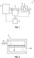
- a further pressure sensor 8 for measuring a downstream exhaust pressure p out can be arranged on the output side of the particle filter 6.
- the ambient pressure can be assumed as the downstream exhaust pressure.
- a differential pressure sensor can also be used to directly record the differential pressure value.
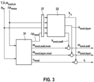
- FIG 2 is a schematic representation of the structure of the particle filter 6.
- the particle filter has an inlet channel 61 and an outlet channel 62, which are separated by a filter element 63 made of filter material.
- the filter element 63 is porous and filters the exhaust gas mass flow flowing through the filter material 63.
- the filter material of the filter element 63 offers a large surface area for the accumulation of soot particles.
- soot particles accumulate on surfaces in the filter material. This loading is indicated as a wall particle loading by a wall loading size.
- soot particles accumulate in a filter cake on the surface of the filter element 63. This loading is indicated as a cake particle loading by a cake loading size. Soot particles are also accumulated to a lesser extent on the walls of the inlet channel 61.
- a method for operating the particle filter 6 is described in more detail below.
- the method can be implemented in the control unit 3 as hardware and/or software and serves to determine a wall loading variable, a cake loading variable and a filter efficiency as loading variables depending on the state variables of the engine system 1.
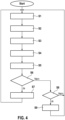
- the block diagram of the Figure 3 shows a loading model 30 with a physical particle filter model 31, which provides a modeled wall loading variable m soot,wall, mod and a cake loading variable m soot,layer,mod based on state variables T, ⁇ soot, in , V ⁇ , p in of the operation of the engine system 1.
- the particle filter model 31 can model a modeled pressure difference specification ⁇ p mod , e.g. as differential pressure p in - p out across the particle filter 6 and also model a filter efficiency ⁇ mod .
- the state variables T, ⁇ soot,in , V ⁇ , p in as well as the modeled pressure difference value ⁇ p mod from the particle filter model 31 and a measured pressure difference value ⁇ p mess (e.g. as the difference between the measured inlet pressure p in and the measured outlet pressure p out of the particle filter 6) are fed to a shift register 37 in order to store time series of the corresponding variables and to provide them to a downstream error model 32.
- the error model 32 is data-based and trained to provide a correction quantity for the wall loading quantity k soot,wall , a correction quantity for the cake loading quantity k soot,layer and a correction quantity k ⁇ for the filter efficiency depending on the time series of the state variables T, ⁇ soot,in , V ⁇ , p in , the modeled pressure difference value ⁇ p mod from the particle filter model 31 and the measured pressure difference value ⁇ p mess .
- the correction variables k soot,wall , k soot,layer and k ⁇ can each be provided as a correction offset and/or correction factor and are applied to the modeled wall loading variable m soot,wall,mod , the modeled cake loading variable m soot,layer,mod and the modeled filter efficiency ⁇ mod in corresponding loading elements 33, 34, 35.
- the corrected wall loading variable m soot,wall , cake loading variable m soot,layer and filter efficiency ⁇ are obtained as output variables.
- the particle filter model 31 can model a modeled pressure difference value ⁇ p mod , e.g. as the differential pressure p in - p out across the particle filter 6.
- step S1 the state variables T, ⁇ soot,in , V ⁇ , p in are first recorded, modeled or provided in step S1.
- step S2 the physical particle filter model 31 accumulates the current particle mass flow in the combustion exhaust gas as a function of the state variables for the modeled wall loading variable m soot,wall,mod , the modeled cake loading variable m soot,layer,mod and further determines the modeled filter efficiency ⁇ mod . Furthermore, the physical particle filter model 31 provides the modeled pressure difference information ⁇ p mod .
- step S3 the state variables T, ⁇ soot,in , V ⁇ , p in stored in the shift register 37 and a measured pressure difference indication ⁇ p mess are temporarily stored in a suitable shift register of the error model in each time step.
- time series of the state variables T, ⁇ soot,in , V ⁇ , p in , the measured pressure difference indication ⁇ p mess and the modeled pressure difference indication ⁇ p mod are provided.
- step S4 the time series of the above variables are fed to the error model 32, which provides the corresponding correction variables k soot,wall , k soot,layer and k ⁇ depending thereon.
- step S5 the corrected wall loading size m soot,wall , the corrected cake loading size m soot,layer and the corrected filter efficiency ⁇ are calculated as output variables from the modelled wall loading size m soot,wall,mod , the modelled cake loading size m soot,layer,mod and the modelled filter efficiency ⁇ mod using the corresponding correction variables, in particular by additive or multiplicative loading.
- step S6 an intervention in the operating strategy for regenerating the particle filter 6 can now be carried out depending on the loading variables m soot,wall , m soot,layer and the filter efficiency ⁇ determined in this way. To do this, it can be checked in step S6 whether the sum of the wall loading variable m soot,wall and the cake loading variable m soot,layer exceeds a predetermined threshold value. If this is the case (alternative: yes), a regeneration cycle is started in step S7 in which the operation of the internal combustion engine 2 is modified so that an increased oxygen input into the combustion exhaust gas occurs and the combustion exhaust gas temperature is also increased.
- step S8 a check is carried out in step S8 to see whether the sum of the wall loading size m soot,wall and the cake loading size m soot,layer falls below a predetermined second threshold value. If this is the case (alternative: yes), a regular regeneration cycle is prevented in step S9 until the second threshold value is exceeded and, if necessary, a scheduled regeneration is not carried out. The method then continues with step S1.
- the error model 32 can be designed as a data-based error model, in particular it is proposed here to design the error model as a temporal convolutional neural network (TCN).
- TCN temporal convolutional neural network
- the architecture of such a neural network is described in the publication Bai S. et al., "An Empirical Evaluation of Generic Convolutional and Recurrent Networks for Sequence Modeling," arxiv:1 802.01271 v2, April 19, 2018 described.
- the error model is trained based on simulations of the loading of the particle filter in conjunction with the provided physical particle filter model. For this purpose, time series of the above state variables are measured or modeled by operating a real combustion engine and the corresponding course of the particle loading of the particle filter is determined using a simulation. In particular, simulated courses of the wall loading variable m soot,wall,mod , the cake loading variable m soot,layer,mod and the filter efficiency ⁇ mod are obtained.
- the physical particle filter model is evaluated based on the state variable curves in order to obtain the curves of the modeled wall loading variable m soot,wall,mod , the modeled cake loading variable m soot,layer,mod and the modeled filter efficiency ⁇ mod as well as the modeled pressure difference value ⁇ p mod .
- the respective correction variables are now determined for the individual support points of these modeled and simulated curves, in particular for additive or multiplicative loading.
- This provides training data sets for training the error model 32, which represent the courses of the state variables T, ⁇ soot,in , V ⁇ , p in , of the modelled Provide the pressure difference value ⁇ p mod and the measured pressure difference value ⁇ p mess and assign these to a correction value for a current time step that corresponds to the last time step of the curves.
- the error model can be trained offline using these training data sets. In this way, the error model 32 can be trained based on the very precise loading simulations of a particle filter.
- the state variable curves taken into account in the loading model correspond to time series of the listed state variables for a predetermined evaluation period or a predetermined length of the time series.
- the time series can correspond to a range between 10 s and 60 s and a number of data sets between 200 and 2,000.
- the error model 32 can be designed as a neural network with an input layer 41, an output layer 42 and a number of, for example, between 5 and 30 residual layers, as in Figure 5 Each layer comprises a number of neuron elements that are functionally connected to neuron elements of other layers.
- the input layer 41 represents a representation of the time series of the state variable curves, the modeled pressure difference information and the measured pressure difference information for the evaluation period.
- the output layer 42 represents a linear classifier in the form of a dense layer in order to provide the relevant correction variables, ie the correction variable for the wall loading variable k soot,wall , the correction variable for the cake loading variable k soot,layer and the correction variable for the filter efficiency k ⁇ .
- Each of the residual layers 43 includes a series of mathematical operations, which are explained below.
- Each residual layer 43 has several sub-networks.
- a first sub-network includes weight normalization
- a second sub-network includes causal convolution
- a third sub-network includes a non-linear activation function and a test-time dropout layer.
- the residual layers 43 are traversed one after the other and the final output of the residual layer 43 is added element by element to the input of the respective residual layer 43.
Landscapes
- Engineering & Computer Science (AREA)
- Chemical & Material Sciences (AREA)
- Combustion & Propulsion (AREA)
- Mechanical Engineering (AREA)
- General Engineering & Computer Science (AREA)
- Chemical Kinetics & Catalysis (AREA)
- Analytical Chemistry (AREA)
- Processes For Solid Components From Exhaust (AREA)
- Filtering Materials (AREA)
Description
- Die Erfindung betrifft Partikelfilter zum Reinigen eines Gasmassenstroms, insbesondere Rußpartikelfilter zum Einsatz in Abgasnachbehandlungseinrichtungen von Kraftfahrzeugen. Weiterhin betrifft die Erfindung Verfahren zur genaueren Bestimmung einer Partikelbeladung eines solchen Partikelfilters.
- Aus der Offenlegungsschrift
DE 10 2004 055 605 A1 ist ein Verfahren zum Bestimmen einer Rußbeladung eines Partikelfilters einer Brennkraftmaschine bekannt. Dabei wird unter anderem eine im Partikelfilter akkumulierte Aschemenge sowie aus einer Druckdifferenz über den Partikelfilter ein Beladungswert für eine Rußbeladung des Partikelfilters bestimmt. Des Weiteren ist ein autoadaptives Modell zur Korrektur des Einflusses von Ascheablagerungen bei der Bestimmung der Rußbeladung in dem Partikelfilter offenbart. - Aus der Offenlegungsschrift
CN 110725738 B ist ein Verfahren zur Bestimmung der Filtrationsfähigkeit eines Dieselpartikelfilters bekannt. Im Rahmen des Verfahrens ist unter anderem vorgesehen, dass ein Pipeline-Luftleckage-Korrekturfaktor bestimmt wird, ein vom Differenzdrucksensor erfasster Wert durch den Pipeline-Luftleckage-Korrekturfaktor korrigiert wird und dann ein korrigierter Druckdifferenzwert erhalten wird. Anhand der Beziehung zwischen dem korrigierten Differenzdruckwert und einem unteren Differenzdruckgrenzwert wird bestimmt, ob die Filterkapazität des Dieselpartikelfilters normal ist oder nicht. - Aus der
Offenlegungsschrift WO2006/055992 A2 ist ein Emissionsmodell bekannt, welches auf Basis von Motorbetriebsdaten, wie etwa Drehzahl, Drehmoment und anderen Größen, einen aktuellen idealen Wert für die vom Motor emittierte Partikelmasse liefert. Zudem wird auch von einem integrierenden Partikelsensor während einer Messdauer eine gemessene reale integrierte Partikelmasse bestimmt. Die modellierte Partikelmasse und die gemessene Partikelmasse werden einem Vergleicheralgorithmus zugeführt. Ein Wert für die Abweichung dieser beiden Ergebnisse wird zur Korrektur des Emissionsmodells weiter verarbeitet. Zur Korrektur des Emissionsmodells gibt es beispielsweise den Vorschlag mittels eines Faktors den Wert für Partikelemission zu korrigieren. - Zur Reduzierung der Partikeldichte in Gasmassenströmen werden üblicherweise Partikelfilter eingesetzt. Beispielsweise werden Partikelemissionen von Verbrennungsmotoren in Kraftfahrzeugen mithilfe von Partikelfiltern reduziert, die einen erheblichen Beitrag zur Reduzierung des Rußpartikelausstoßes von Dieselmotoren und Ottomotoren leisten. Die Partikelfilter werden beim Betrieb des Verbrennungsmotors durch Asche und Rußpartikel beladen, die sich darin in der Wand und im Filterkuchen absetzen. In einem Regenerationsprozess wird in regelmäßigen Zeitabständen unter Zufuhr von Sauerstoff und durch erhöhte Abgastemperaturen die Beladung mit Ruß abgebrannt, um den Partikelfilter zu regenerieren und diesen in einem optimalen Betriebszustand zu halten.
- Erfindungsgemäß sind ein Verfahren zum Bestimmen einer Beladung eines Partikelfilters, insbesondere für die Reinigung von Verbrennungsabgas eines Verbrennungsmotors, gemäß Anspruch 1, und Computerprogrammprodukt und ein maschinenlesbares Speichermedium gemäß den nebengeordneten Ansprüchen vorgesehen.
- Weitere Ausgestaltungen sind in den abhängigen Ansprüchen angegeben.
- Gemäß einem ersten Aspekt ist ein Verfahren zum Bestimmen einer Partikelbeladung eines Partikelfilters als mindestens eine Beladungsgröße für einen Verbrennungsmotor vorgesehen, mit folgenden Schritten:
- Erfassen oder Bereitstellen von mehreren Zustandsgrößen des zugeführten Gasmassenstroms, die zumindest einen Partikelmassenstrom und eine Druckunterschiedsangabe für einen tatsächlichen Druckunterschied zwischen einer Eingangsseite und einer Ausgangsseite des Partikelfilters umfassen;
- Bestimmen mindestens einer modellierten Beladungsgröße mithilfe eines physikalischen Partikelfiltermodells abhängig von einer oder mehreren Zustandsgrößen eines zugeführten Gasmassenstroms;
- Modellieren einer Korrekturgröße für die mindestens eine modellierte Beladungsgröße mithilfe eines datenbasierten Fehlermodells abhängig von den Zustandsgrößen des zugeführten Gasmassenstroms, der Druckunterschiedsangabe, wobei das Fehlermodell ein temporales konvolutionelles Netzwerk (TCM: temporal convolutional network) umfasst oder diesem entspricht;
- Bestimmen der mindestens einen Beladungsgröße abhängig von der mindestens einen modellierten Beladungsgröße und der modellierten Korrekturgröße.
- Die Beladung eines Partikelfilters ist eine essentielle Größe, die das Systemverhalten des Systems, in dem der Partikelfilter betrieben wird, maßgeblich beeinflusst. Bei einer zu hohen Beladung wird ein hoher Gasgegendruck durch den Partikelfilter bewirkt, der zu einem erhöhten Energieverbrauch des Systems oder sogar zu einer mechanischen Beschädigung des Partikelfilters führen kann. Beim Einsatz des Partikelfilters als Abgaspartikelfilter für einen Verbrennungsmotor in einem Kraftfahrzeug führt dies zu einem erhöhten Kraftstoffverbrauch des Verbrennungsmotors.
- Weiterhin ist der Filterwirkungsgrad für einen zu gering beladenen Partikelfilter gering, so dass eine Mindestbeladung mit Partikeln für einen ausreichenden Filterwirkungsgrad notwendig ist.
- Daher ist es wichtig, die Beladung des Partikelfilters auf einem moderaten Niveau, d.h. in einem bestimmten Bereich, zu halten, um den Filterwirkungsgrad des Filters hinsichtlich Filterung und den Energieverbrauch des gesamten Systems zu optimieren.
- Dies erfordert eine Kenntnis der aktuellen Beladung des Partikelfilters, um diese in geeigneter Weise beeinflussen zu können. Das Maß der Beladung des Partikelfilters, das mit einer Beladungsgröße angegeben werden kann, kann durch Aktivieren oder Vermeiden eines Regenerationszyklus eingestellt bzw. verändert werden.
- Ein derartiger Regenerationszyklus sieht beispielsweise zur Reduzierung der Beladung eines Rußpartikelfilters für einen Verbrennungsmotor vor, durch Zufuhr von Sauerstoff und Erhöhung der Temperatur im Partikelfilter, die Rußpartikel abzubrennen und diese dadurch aus dem Filter zu entfernen.
- Jedoch kann die Beladung eines Partikelfilters nicht direkt gemessen werden, so dass diese auf Basis von verfügbaren Größen während des Betriebs des Systems, wie z.B. des Motorsystems mit dem Verbrennungsmotor, mithilfe eines Partikelfiltermodells modellhaft ermittelt werden muss. Herkömmliche Partikelfiltermodelle sind in der Regel physikalisch basierte Modelle, die das komplexe Verhalten eines Partikelfilters abhängig von Zustandsgrößen abbilden. Gängige Partikelfiltermodelle sind jedoch in der Genauigkeit beschränkt, insbesondere während eines Regenerationszyklus. Zwar sind auch detaillierte Simulationsmodelle für Partikelfilter bekannt, diese eignen sich jedoch nicht für die Online-Berechnung einer Beladungsgröße.
- Daher sieht obiges Verfahren vor, ein physikalisches Partikelfiltermodell zu verwenden, das mithilfe eines datenbasierten Fehlermodells korrigiert wird. Das datenbasierte Fehlermodell kann eine Korrekturgröße, z.B. in Form eines Korrektur-Offsets oder eines Korrekturfaktors, für die Korrektur der mindestens einen modellierten Beladungsgröße bereitstellen.
- Das Fehlermodell kann trainiert werden, um abhängig von Verläufen der Zustandsgrößen, der Druckunterschiedsangabe eine jeweilige Korrekturgröße für die jeweilige Beladungsgröße anzugeben, wobei die jeweilige Korrekturgröße ausgebildet ist, die jeweilige Beladungsgröße zu beaufschlagen, insbesondere additiv oder multiplikativ zu beaufschlagen.
- Das Fehlermodell kann durch Offline-Simulationen des Partikelfilters abhängig von den Zustandsgrößen des Systems und abhängig von einem Unterschied eines realen Werts der mindestens einen Beladungsgröße und eines modellierten Werts der mindestens einen Beladungsgröße trainiert werden.
- Da das physikalische Partikelfiltermodell die Beladung abhängig von einer Akkumulation eines Partikelmassenstroms ermittelt, ist es notwendig, eine Struktur des Fehlermodells so vorzusehen, das die Korrekturgröße unter Berücksichtigung des dynamischen Verhaltens des Partikelfilters bestimmt wird. Dies ermöglicht es, dass das Fehlermodell auch akkumulierte Fehler des Partikelfiltermodells abbilden kann, wobei die für die Bestimmung der Beladungsgröße zu berücksichtigenden Zeitreihen sehr lang sein können.
- Überraschenderweise wurde festgestellt, dass die Verwendung eines temporalen konvolutionellen Netzwerks (TCN) als Fehlermodell besonders geeignet ist, um die Abweichungen einer modellierten Beladungsgröße von einer realen Beladung des Partikelfilters abzubilden. Insbesondere bei langen Zeitreihen hat sich die Verwendung eines temporalen konvolutionellen Netzwerks als Fehlermodell als genauer und weniger komplex gegenüber herkömmlichen rekurrenten neuronalen Netzen, wie LSTM oder GRU, herausgestellt, die dynamisches Verhalten nur für kürzere Zeithorizonte mit guter Genauigkeit abbilden können.
- Die Zustandsgrößen können einen Gasvolumenstrom, eine Temperatur und/oder einen Druck umfassen.
- Die mindestens eine Beladungsgröße und die mindestens eine modellierte Beladungsgröße können umfassen:
- eine Wandbeladungsgröße, die eine Menge an Oberflächen eines Filtermaterials des Partikelfilters angelagerten Partikel angibt, und eine modellierte Wandbeladungsgröße, die eine modellierte Menge an Oberflächen des Filtermaterials des Partikelfilters angelagerten Partikel angibt; und/oder,
- eine Kuchenbeladungsgröße, die eine Menge in einem Kuchen auf einer Oberfläche eines Filterelements des Partikelfilters abgelagerten Partikel angibt, und eine modellierte Kuchenbeladungsgröße, die eine modellierte Menge in einem Kuchen auf einer Oberfläche eines Filterelements des Partikelfilters abgelagerten Partikel angibt; und/oder
- einen Filterwirkungsgrad, der die Reinigungseffizienz des Partikelfilters angibt, und einen modellierten Filterwirkungsgrad, der die modellierte Reinigungseffizienz des Partikelfilters angibt.
- Es kann vorgesehen sein, dass eine modellierte Druckunterschiedsangabe zwischen eingangsseitigem und ausgangsseitigem Druck über dem Partikelfilter mithilfe des physikalischen Partikelfiltermodells ermittelt wird, wobei die Korrekturgröße für die mindestens eine modellierte Beladungsgröße mithilfe des datenbasierten Fehlermodells weiterhin abhängig von der modellierten Druckunterschiedsangabe durchgeführt wird, wobei das Fehlermodell trainiert ist, um abhängig von Verläufen der Zustandsgrößen, der Druckunterschiedsangabe und der modellierten Druckunterschiedsangabe die jeweilige Korrekturgröße zur Ermittlung der jeweiligen Beladungsgröße anzugeben, wobei die jeweilige Korrekturgröße ausgebildet ist, die jeweilige modellierte Beladungsgröße zu beaufschlagen, insbesondere additiv oder multiplikativ zu beaufschlagen.
- Es kann vorgesehen sein, dass das Verfahren zyklisch in Zeitschritten ausgeführt wird, wobei in jedem Zeitschritt die Werte der Zustandsgrößen, der Druckunterschiedsangabe und der modellierten Druckunterschiedsangabe zwischengespeichert werden, wobei dem Fehlermodell Zeitreihen der Zustandsgrößen, der Druckunterschiedsangabe und der modellierten Druckunterschiedsangabe für einen zurückliegenden Auswertungszeitraum bereitgestellt werden.
- Weiterhin kann abhängig von der mindestens einen Beladungsgröße der Partikelfilter regeneriert werden oder eine planmäßige Regeneration des Partikelfilters unterbunden werden.
- Gemäß einer Ausführungsform kann der Partikelfilter als ein Abgaspartikelfilter in einer Abgasnachbehandlungseinrichtung eines Kraftfahrzeugs verwendet werden.
- Gemäß einer weiteren Ausführungsform kann das temporale konvolutionelle Netzwerk des Fehlermodells mit zwischen 5 und 30 residualen Schichten gebildet sein, die ein erstes Unternetzwerk für eine Normalisierung und ein zweites Unternetzwerk für eine kausale Konvolution mit einer sich zu weiter nachgeordneten residualen Schichten erhöhenden Dilationsrate aufweist.
- Ausführungsformen werden nachfolgend anhand der beigefügten Zeichnungen näher erläutert. Es zeigen:
- Figur 1
- eine schematische Darstellung eines Motorsystems mit einem Verbrennungsmotor und einem Partikelfilter zum Reinigen des Verbrennungsabgases;
- Figur 2
- eine schematische Darstellung des Aufbaus des Partikelfilters;
- Figur 3
- ein Blockdiagramm zur Veranschaulichung der Funktion zum Bereitstellen einer korrigierten Ladungsgröße;
- Figur 4
- ein Flussdiagramm zur Veranschaulichung eines Verfahrens zum Bestimmen einer Beladungsgröße eines Partikelfilters und zum Betreiben des Motorsystems der
Figur 1 ; und - Figur 5
- eine detailliertere Darstellung der Architektur des Fehlermodells als temporales konvolutionelles Netzwerk.
-
Figur 1 zeigt eine schematische Darstellung eines Motorsystems 1 mit einem Verbrennungsmotor 2, als Beispiel für ein System mit einem Partikelfilter. Der Verbrennungsmotor 2 kann ein Diesel- oder Ottomotor sein, der mithilfe einer Steuereinheit 3 betrieben wird. Über einen Abgasabführungsabschnitt 4 stößt der Verbrennungsmotor 2 Verbrennungsabgas aus, das einer Abgasnachbehandlungseinrichtung 5 mit einem Partikelfilter 6 zugeführt wird. Im Abgasabführungsabschnitt 4 können ein oder mehrere Sensoren 7 angeordnet sein, um Zustandsgrö-βen des Betriebs des Motorsystems 1 sensorisch oder modellbasiert zu erfassen, wie beispielsweise ein Temperatursensor 9 zur Erfassung einer Abgastemperatur T und ein Eingangsdrucksensor 7 zur Erfassung eines Abgasgegendruck pin, der als Eingangsdruck des Partikelfilters 6 bereitgestellt wird, wobei abhängig von dem Betriebspunkt und der Last und Drehzahl des Verbrennungsmotors 2 weitere Zustandsgrößen, wie beispielsweise ein Abgasmassenstrom V, sowie eine Rußbeladung ṁsoot,in des Verbrennungsabgases, mithilfe geeigneter in der Steuereinheit 3 implementierter Modelle modelliert werden können. - Ausgangsseitig des Partikelfilters 6 kann ein weiterer Drucksensor 8 zur Messung einer stromabwärtigen Abgasdrucks pout angeordnet sein. Alternativ kann als stromabwärtiger Abgasdruck der Umgebungsdruck angenommen werden. Alternativ kann auch ein Differenzdrucksensor zur direkten Erfassung der Differenzdruckangabe verwendet werden.
- In
Figur 2 ist eine schematische Darstellung des Aufbaus des Partikelfilters 6 dargestellt. Der Partikelfilter weist einen Einlasskanal 61 und einen Auslasskanal 62 auf, die durch ein Filterelement 63 aus Filtermaterial getrennt sind. Das Filterelement 63 ist porös und filtert den durch das Filtermaterial 63 durchströmenden Abgasmassenstrom. Das Filtermaterial des Filterelements 63 bietet eine große Oberfläche zur Anlagerung von Rußpartikeln. Beim Abscheideprozess von Rußpartikeln kommt es zu einer Anlagerung von Rußpartikeln auf Oberflächen in dem Filtermaterial. Diese Beladung wird als Wandpartikelbeladung durch eine Wandbeladungsgröße angegeben. Weiterhin kommt es beim Abscheideprozess von Rußpartikeln zu einer Anlagerung von Rußpartikeln in einem Filterkuchen auf der Oberfläche des Filterelements 63. Diese Beladung wird als Kuchenpartikelbeladung durch eine Kuchenbeladungsgröße angegeben. Auch werden in geringerem Umfang Rußpartikel an den Wänden des Einlasskanals 61 angelagert. - In Verbindung mit dem Funktionsblockschaltbild der
Figur 3 und dem Flussdiagramm derFigur 4 wird nachfolgend ein Verfahren zum Betreiben des Partikelfilters 6 näher beschrieben. Das Verfahren kann in der Steuereinheit 3 als Hardware und/oder Software implementiert sein und dient dazu abhängig von den Zustandsgrößen des Motorsystems 1 als Beladungsgrößen eine Wandbeladungsgröße, eine Kuchenbeladungsgrößen und einen Filterwirkungsgrad zu ermitteln. - Das Blockschaltbild der
Figur 3 zeigt ein Beladungsmodell 30 mit einem physikalischen Partikelfiltermodell 31, das ausgehend von Zustandsgrößen T, ṁ soot,in , V̇, pin des Betriebs des Motorsystems 1 eine modellierte Wandbeladungsgröße msoot,wall,mod und eine Kuchenbeladungsgröße msoot,layer,mod bereitstellt. Weiterhin kann das Partikelfiltermodell 31 eine modellierte Druckunterschiedsangabe Δpmod , z.B. als Differenzdruck pin - pout über dem Partikelfilter 6 modellieren und weiterhin einen Filterwirkungsgrad ηmod modellieren. - Weiterhin werden die Zustandsgrößen T, ṁsoot,in , V̇ , pin sowie die modellierte Druckunterschiedsangabe Δpmod aus dem Partikelfiltermodell 31 und eine gemessene Druckunterschiedsangabe Δpmess (z.B. als Differenz aus dem gemessenen Eingangsdruck pin und dem gemessenen Ausgangsdruck pout des Partikelfilters 6) einem Schieberegister 37 zugeführt, um Zeitreihen der entsprechenden Größen zu speichern und diese einem nachgelagerten Fehlermodell 32 bereitzustellen. Das Fehlermodell 32 ist datenbasiert und trainiert, um eine Korrekturgröße für die Wandbeladungsgröße ksoot,wall, eine Korrekturgröße für die Kuchenbeladungsgröße ksoot,layer und eine Korrekturgröße kη für den Filterwirkungsgrad abhängig von den Zeitreihen der Zustandsgrößen T, ṁsoot,in , V̇ , pin, der modellierten Druckunterschiedsangabe Δpmod aus dem Partikelfiltermodell 31 und der gemessenen Druckunterschiedsangabe Δpmess bereitzustellen.
- Die Korrekturgrößen ksoot,wall, ksoot,layer und kη können jeweils als Korrekturoffset und/oder Korrekturfaktor bereitgestellt werden und werden in entsprechenden Beaufschlagungselementen 33, 34, 35 der modellierten Wandbeladungsgröße msoot,wall,mod, der modellierten Kuchenbeladungsgröße msoot,layer,mod und dem modellierten Filterwirkungsgrad ηmod beaufschlagt. Auf diese Weise erhält man die korrigierte Wandbeladungsgröße msoot,wall, Kuchenbeladungsgröße msoot,layer und Filterwirkungsgrad η als Ausgangsgrößen. Weiterhin kann das Partikelfiltermodell 31 eine modellierte Druckunterschiedsangabe Δpmod , z.B. als Differenzdruck pin - pout über dem Partikelfilter 6 modellieren.
- In dem Flussdiagramm der
Fig. 4 , das zyklisch ausgeführt wird, werden zunächst in Schritt S1 die Zustandsgrößen T, ṁsoot,in , V̇ , pin erfasst bzw. modelliert oder bereitgestellt. - Das physikalische Partikelfiltermodell 31 akkumuliert in Schritt S2 den aktuellen Partikelmassenstrom in dem Verbrennungsabgas abhängig von den Zustandsgrö-βen zu der modellierten Wandbeladungsgröße msoot,wall,mod, der modellierten Kuchenbeladungsgröße msoot,layer,mod und ermittelt weiterhin den modellierten Filterwirkungsgrad ηmod . Weiterhin wird von dem physikalischen Partikelfiltermodell 31 die modellierte Druckunterschiedsangabe Δpmod bereitgestellt.
- In Schritt S3 werden die Zustandsgrößen T, ṁsoot,in, V̇ , pin, die in dem Schieberegister 37 und eine gemessene Druckunterschiedsangabe Δpmess in einem geeigneten Schieberegister des Fehlermodells in jedem Zeitschritt zwischengespeichert. Auf diese Weise werden Zeitreihen der Zustandsgrößen T, ṁsoot,in, V̇ , pin der gemessenen Druckunterschiedsangabe Δpmess und der modellierten Druckunterschiedsangabe Δpmod bereitgestellt.
- Weiterhin werden in Schritt S4 die Zeitreihen der obigen Größen dem Fehlermodell 32 zugeführt, das davon abhängig die entsprechenden Korrekturgrößen ksoot,wall, ksoot,layer und kη bereitstellt.
- In Schritt S5 wird die korrigierte Wandbeladungsgröße msoot,wall, die korrigierte Kuchenbeladungsgröße msoot,layer und der korrigierte Filterwirkungsgrad η als Ausgangsgrößen aus der modellierten Wandbeladungsgröße msoot,wall,mod , der modellierten Kuchenbeladungsgröße msoot,layer,mod und dem modellierten Filterwirkungsgrad ηmod mithilfe der entsprechenden Korrekturgrößen berechnet, insbesondere durch additive oder multiplikative Beaufschlagung.
- In Schritt S6 kann nun abhängig von den so ermittelten Beladungsgrößen msoot,wall, msoot,layer und dem Filterwirkungsgrad η ein Eingriff in die Betriebsstrategie zur Regeneration des Partikelfilters 6 vorgenommen werden. Dazu kann in Schritt S6 überprüft werden, ob die Summe der Wandbeladungsgröße msoot,wall und der Kuchenbeladungsgröße msoot,layer einen vorgegebenen Schwellenwert übersteigt. Ist dies der Fall (Alternative: Ja), wird in Schritt S7 ein Regenerationszyklus gestartet, in dem der Betrieb des Verbrennungsmotors 2 so modifiziert wird, dass ein erhöhter Sauerstoffeintrag in dem Verbrennungsabgas erfolgt und weiterhin die Verbrennungsabgastemperatur erhöht ist.
- Wird der Schwellenwert nicht überschritten (Alternative: Nein), so wird in Schritt S8 überprüft, ob die Summe der Wandbeladungsgröße msoot,wall und der Kuchenbeladungsgröße msoot,layer einen vorgegebenen zweiten Schwellenwert unterschreitet. Ist dies der Fall (Alternative: Ja), so wird in Schritt S9 ein regelmäßiger Regenerationszyklus bis zu einem Überschreiten des zweiten Schwellenwerts unterbunden und gegebenenfalls eine planmäßige Regeneration nicht durchgeführt. Anschließend wird das Verfahren mit Schritt S1 fortgesetzt.
- Das Fehlermodell 32 kann als datenbasiertes Fehlermodell ausgebildet sein, insbesondere wird hierin vorgeschlagen, das Fehlermodell als temporales konvolutionelles neuronales Netz (TCN: temporal convolutional neural network) auszubilden. Die Architektur eines solchen neuronalen Netzes ist in der Druckschrift Bai S. et al., "An Empirical Evaluation of Generic Convolutional and Recurrent Networks for Sequence Modelling", arxiv:1 802.01271 v2, 19. April 2018 beschrieben.
- Das Fehlermodell wird trainiert basierend auf Simulationen der Beladung des Partikelfilters in Verbindung mit dem bereitgestellten physikalischen Partikelfiltermodell. Dazu werden Zeitreihen der obigen Zustandsgrößen durch den Betrieb eines realen Verbrennungsmotors gemessen oder modelliert und mithilfe einer Simulation den entsprechenden Verlauf der Partikelbeladung des Partikelfilters zu ermitteln. Insbesondere erhält man so simulierte Verläufe der Wandbeladungsgröße msoot,wall,mod, der Kuchenbeladungsgröße msoot,layer,mod und des Filterwirkungsgrads ηmod .
- Weiterhin werden basierend auf den Zustandsgrößenverläufen das physikalische Partikelfiltermodell ausgewertet, um die Verläufe der modellierten Wandbeladungsgröße msoot,wall,mod, der modellierten Kuchenbeladungsgröße msoot,layer,mod und dem modellierten Filterwirkungsgrad ηmod sowie der modellierten Druckunterschiedsangabe Δpmod zu erhalten. Zu den einzelnen Stützstellen dieser modellierten und simulierten Verläufe werden nun die jeweiligen Korrekturgrößen insbesondere zur additiven oder multiplikativen Beaufschlagung bestimmt.
- Dadurch werden Trainingsdatensätze für das Trainieren des Fehlermodells 32 ermittelt, die Verläufe der Zustandsgrößen T, ṁsoot,in , V̇ , pin , der modellierten Druckunterschiedsangabe Δpmod und der gemessenen Druckunterschiedsangabe Δpmess bereitstellen und diese einer Korrekturgröße zu einem aktuellen Zeitschritt zuordnen, der dem letzten Zeitschritt der Verläufe entspricht. Das Fehlermodell kann mit diesen Trainingsdatensätzen offline trainiert werden. Auf diese Weise kann das Fehlermodell 32 basierend auf den sehr genau ausführbaren Beladungssimulationen eines Partikelfilters trainiert werden.
- Die in dem Beladungsmodell berücksichtigten Zustandsgrößenverläufe entsprechen Zeitreihen der der aufgeführten Zustandsgrößen für einen vorbestimmten Auswertungszeitraum bzw. eine vorbestimmte Länge der Zeitreihe. Beispielsweise kann die Zeitreihe einem Bereich zwischen 10 s und 60 s und einer Anzahl von Datensätzen zwischen 200 und 2.000 entsprechen.
- Das Fehlermodell 32 kann als neuronales Netz mit einer Eingangsschicht 41, einer Ausgangsschicht 42 und einer Anzahl von beispielsweise zwischen 5 und 30 residualen Schichten ausgebildet sein, wie in
Figur 5 dargestellt. Jede Schicht umfasst eine Anzahl von Neuronenelementen, die funktional mit Neuronenelementen anderer Schichten verbunden sind. - Die Eingangsschicht 41 stellt eine Repräsentation der Zeitreihen der Zustandsgrößenverläufe, der modellierten Druckunterschiedsangabe und der gemessenen Druckunterschiedsangabe für den Auswertungszeitraum dar. Die Ausgangsschicht 42 stellt einen linearen Klassifizierer in Form eines Dense Layers dar, um die betreffenden Korrekturgrößen, d.h. die Korrekturgröße für die Wandbeladungsgröße ksoot,wall, die Korrekturgröße für die Kuchenbeladungsgröße ksoot,layer und die Korrekturgröße für den Filterwirkungsgrad kη bereitzustellen.
- Jede der residualen Schichten 43 umfasst eine Reihe von mathematischen Operationen, die nachfolgend erläutert werden. Jede residuale Schicht 43 weist mehrere Unternetzwerke auf. Ein erstes Unternetzwerk umfasst eine Gewichtungsnormalisierung, ein zweites Unternetzwerk eine kausale Konvolution, und eine drittes Unternetzwerk eine nichtlineare Aktivierungsfunktion und eine Testzeit-Dropout-Schicht.
- Ein Zustandsgrößenverlauf mit einer Zeitreihe von


- Das entsprechende Ausgangssignal


- Mithilfe eines optionalen Dropout-Prozesses kann ein Modellparameter in allen Neuronenschichten des neuronalen Netzes außer der Ausgangsschicht zufällig und mit einer bestimmten Wahrscheinlichkeit zu null gesetzt werden. Beim Training des Fehlermodells vermeidet man durch diese Maßnahme ein Overfitting des Modells. In der Anwendung des Fehlermodells für die Prädiktion kann bei einer wiederholten Berechnung mit denselben Eingangsgrößen und Anwendung der Dropout Maßnahme ein entsprechend stochastisches Ausgangssignal erzeugen, das zur Ermittlung der Korrekturgröße ausgewertet werden kann, siehe auch Yarin Gal et al. "Dropout as a Bayesian Approximation: Representing Model Uncertainty in Deep Learning", University of Cambridge, https://arxiv.org/pdf/1506.02142.pdf.

- ct ~ Bernoulli(1 - p)
- mit p einer vorgegebenen Dropout-Rate.
- Die residualen Schichten 43 werden nacheinander durchlaufen und der finale Ausgang der residualen Schicht 43 wird elementenweise auf den Eingang der jeweiligen residualen Schicht 43 addiert.
Claims (11)
- Verfahren zum Bestimmen einer Partikelbeladung eines Partikelfilters (6) mit mindestens einer Beladungsgröße, mit folgenden Schritten:- Erfassen (S1) oder Bereitstellen von mehreren Zustandsgrößen (T, ṁsoot,in , V̇ , pin) eines zugeführten Gasmassenstroms, die zumindest einen Partikelmassenstrom und eine insbesondere gemessene Druckunterschiedsangabe (Δpmess ) für einen tatsächlichen Druckunterschied zwischen einer Eingangsseite und einer Ausgangsseite des Partikelfilters (6) umfassen;- Bestimmen (S2) mindestens einer modellierten Beladungsgröße (msoot,wall,mod, msoot,layer,mod ) mithilfe eines physikalischen Partikelfiltermodells (31) abhängig von der einen oder den mehreren Zustandsgrößen (T, ṁsoot,in , V̇ , pin) des zugeführten Gasmassenstroms;- Modellieren (S4) einer Korrekturgröße (ksoot,wall, ksoot,layer , kη) für die mindestens eine modellierte Beladungsgröße (msoot,wall,mod, msoot,layer,mod ) mithilfe eines datenbasierten Fehlermodells (32) abhängig von den Zustandsgrößen (T, ṁsoot,in , V̇ , pin) des zugeführten Gasmassenstroms, der Druckunterschiedsangabe (Δpmess ), wobei das Fehlermodell (32) einem temporalen konvolutionellen Netzwerk (TCM: temporal convolutional network) entspricht oder ein solches umfasst;- Bestimmen (S5) der mindestens einen Beladungsgröße (msoot,wall, msoot,layer ) abhängig von der mindestens einen modellierten Beladungsgröße (msoot,wall,mod, msoot,layer,mod ) und der modellierten Korrekturgröße (ksoot,wall, ksoot,layer , kη).
- Verfahren nach Anspruch 1, wobei die Zustandsgrößen (T, ṁsoot,in , V̇ , pin) ein Gasvolumenstrom (ṁsoot,in ), eine Temperatur (T) und/oder einen Druck umfassen.
- Verfahren nach einem der Ansprüche 1 und 2, wobei die Beladungsgröße (msoot,wall, msoot,layer ) und die modellierte Beladungsgröße (msoot,wall,mod, msoot,layer,mod ) umfassen:- - eine Wandbeladungsgröße (msoot,wall, msoot,wall,mod ), die eine Menge an Oberflächen eines Filtermaterials (63) des Partikelfilters (6) angelagerten Partikel angibt, und eine modellierte Wandbeladungsgröße, die eine modellierte Menge an Oberflächen des Filtermaterials (63) des Partikelfilters (6) angelagerten Partikel angibt; und/oder,- - eine Kuchenbeladungsgröße (msoot,layer, msoot,layer,mod ), die eine Menge in einem Kuchen auf einer Oberfläche eines Filterelements des Partikelfilters (6) abgelagerten Partikel angibt, und eine modellierte Kuchenbeladungsgröße, die eine modellierte Menge in einem Kuchen auf einer Oberfläche eines Filterelements (63) des Partikelfilters (6) abgelagerten Partikel angibt; und/oder- - einen Filterwirkungsgrad (η), der die Reinigungseffizienz des Partikelfilters (6) angibt, und einen modellierten Filterwirkungsgrad, der die modellierte Reinigungseffizienz des Partikelfilters (6) angibt.
- Verfahren nach einem der Ansprüche 1-3, wobei das Fehlermodell (32) trainiert ist, um abhängig von Verläufen der Zustandsgrößen (T, ṁsoot,in , V̇ , pin), der Druckunterschiedsangabe (Δpmess ) und der modellierten Druckunterschiedsangabe (Δpmod ) die jeweilige Korrekturgröße (ksoot,wall, ksoot,layer , kη) für die jeweilige Beladungsgröße anzugeben, wobei die jeweilige Korrekturgröße (ksoot,wall, ksoot,layer , kη) ausgebildet ist, die jeweilige modellierte Beladungsgröße (msoot,wall,mod, msoot,layer,mod ) zu beaufschlagen, insbesondere additiv oder multiplikativ zu beaufschlagen.
- Verfahren nach einem der Ansprüche 1-4, wobei eine modellierte Druckunterschiedsangabe (Δpmod ) zwischen eingangsseitigem und ausgangsseitigem Druck über dem Partikelfilter (6) mithilfe des physikalischen Partikelfiltermodells (31) ermittelt wird, wobei die Korrekturgröße (ksoot,wall, ksoot,layer , kη) für die mindestens eine modellierte Beladungsgröße (msoot,wall,mod, msoot,layer,mod ) mithilfe des datenbasierten Fehlermodells (32) weiterhin abhängig von der modellierten Druckunterschiedsangabe (Δpmod ) durchgeführt wird, wobei das Fehlermodell (32) trainiert ist, um abhängig von Verläufen der Zustandsgrö-βen (T, ṁsoot,in , V̇ , pin), der Druckunterschiedsangabe (Δpmess ) und der modellierten Druckunterschiedsangabe (Δpmod ) die jeweilige Korrekturgröße (ksoot,wall, ksoot,layer , kη) zur Ermittlung der jeweiligen Beladungsgröße (msoot,wall, msoot,layer ) anzugeben, wobei die jeweilige Korrekturgröße (ksoot,wall, ksoot,layer , kη) ausgebildet ist, die jeweilige modellierte Beladungsgröße (msoot,wall,mod, msoot,layer,mod ) zu beaufschlagen, insbesondere additiv oder multiplikativ zu beaufschlagen.
- Verfahren nach einem der Ansprüche 1-5, wobei das Verfahren zyklisch in Zeitschritten ausgeführt wird, wobei in jedem Zeitschritt die Werte der Zustandsgrößen (T, ṁsoot,in , V , Pin), der Druckunterschiedsangabe (Δpmess ) und ggfs. der modellierten Druckunterschiedsangabe (Δpmod ) zwischengespeichert werden, wobei dem Fehlermodell (32) Zeitreihen der Zustandsgrö-βen (T, ṁsoot,in , V̇ , pin), der Druckunterschiedsangabe (Δpmess ) und ggfs. der modellierten Druckunterschiedsangabe (Δpmod ) für einen zurückliegenden Auswertungszeitraum bereitgestellt wird.
- Verfahren nach einem der Ansprüche 1-6, wobei abhängig von der mindestens einen Beladungsgröße (msoot,wall, msoot,layer ) der Partikelfilter (6) regeneriert wird oder eine planmäßige Regeneration des Partikelfilters (6) unterbunden wird.
- Verfahren nach einem der Ansprüche 1-7, wobei der Partikelfilter (6) als ein Abgaspartikelfilter in einer Abgasnachbehandlungseinrichtung eines Kraftfahrzeugs verwendet wird.
- Verfahren nach einem der Ansprüche 1-8, wobei das temporale konvolutionelle Netzwerk zwischen 5 und 30 residuale Schichten aufweist, die ein erstes Unternetzwerk für eine Normalisierung und ein zweites Unternetzwerk für eine kausale Konvolution mit einer sich zu weiter nachgeordneten residualen Schichten erhöhenden Dilationsrate aufweist.
- Computerprogrammprodukt, umfassend Befehle, die bei der Ausführung des Programms durch eine Steuereinheit eines Verbrennungsmotors diese veranlassen, die Schritte des Verfahrens nach einem der Ansprüche 1 bis 9 auszuführen.
- Maschinenlesbares Speichermedium, umfassend Befehle, die bei der Ausführung durch eine Steuereinheit eines Verbrennungsmotors diese veranlassen, die Schritte des Verfahrens nach einem der Ansprüche 1 bis 9 auszuführen.
Priority Applications (2)
| Application Number | Priority Date | Filing Date | Title |
|---|---|---|---|
| EP21170347.5A EP4083398B1 (de) | 2021-04-26 | 2021-04-26 | Verfahren zum bestimmen einer partikelbeladung eines partikelfilters, insbesondere zum einsatz in einer abgasnachbehandlungseinrichtung für einen verbrennungsmotor |
| CN202210437394.1A CN115247590A (zh) | 2021-04-26 | 2022-04-25 | 用于确定颗粒过滤器的颗粒装载量的方法和设备 |
Applications Claiming Priority (1)
| Application Number | Priority Date | Filing Date | Title |
|---|---|---|---|
| EP21170347.5A EP4083398B1 (de) | 2021-04-26 | 2021-04-26 | Verfahren zum bestimmen einer partikelbeladung eines partikelfilters, insbesondere zum einsatz in einer abgasnachbehandlungseinrichtung für einen verbrennungsmotor |
Publications (2)
| Publication Number | Publication Date |
|---|---|
| EP4083398A1 EP4083398A1 (de) | 2022-11-02 |
| EP4083398B1 true EP4083398B1 (de) | 2024-12-04 |
Family
ID=75674654
Family Applications (1)
| Application Number | Title | Priority Date | Filing Date |
|---|---|---|---|
| EP21170347.5A Active EP4083398B1 (de) | 2021-04-26 | 2021-04-26 | Verfahren zum bestimmen einer partikelbeladung eines partikelfilters, insbesondere zum einsatz in einer abgasnachbehandlungseinrichtung für einen verbrennungsmotor |
Country Status (2)
| Country | Link |
|---|---|
| EP (1) | EP4083398B1 (de) |
| CN (1) | CN115247590A (de) |
Families Citing this family (2)
| Publication number | Priority date | Publication date | Assignee | Title |
|---|---|---|---|---|
| CN116480449B (zh) * | 2023-04-17 | 2025-07-18 | 潍柴动力股份有限公司 | 确定碳载量过载的方法、装置、存储介质和电子设备 |
| CN117090669B (zh) * | 2023-09-25 | 2026-04-21 | 潍柴动力股份有限公司 | 碳载量确定方法、装置、计算机可读存储介质及电子设备 |
Family Cites Families (6)
| Publication number | Priority date | Publication date | Assignee | Title |
|---|---|---|---|---|
| DE102004055605B4 (de) * | 2004-11-18 | 2015-10-29 | Volkswagen Ag | Verfahren zum Bestimmen einer Rußbeladung eines Partikelfilters |
| CN102787890B (zh) * | 2004-11-25 | 2015-04-15 | Avl里斯脱有限公司 | 用于确定沉积在位于内燃机的排气管中的微粒过滤器内的微粒负荷的方法 |
| DE102014209840A1 (de) * | 2014-05-23 | 2015-11-26 | Robert Bosch Gmbh | Verfahren und Vorrichtung zur Diagnose eines Partikelfilters |
| DE102017218195A1 (de) * | 2017-10-12 | 2019-04-18 | Robert Bosch Gmbh | Verfahren und Vorrichtung zum Ermitteln einer Rußkonzentration in einem Verbrennungsabgas eines Verbrennungsmotors |
| DE102018125730A1 (de) * | 2018-10-17 | 2020-04-23 | Robert Bosch Gmbh | Verfahren zur Bestimmung der Beladung eines Rußfilters |
| CN110725738B (zh) * | 2019-12-17 | 2020-03-17 | 潍柴动力股份有限公司 | Dpf过滤能力的检测方法及装置 |
-
2021
- 2021-04-26 EP EP21170347.5A patent/EP4083398B1/de active Active
-
2022
- 2022-04-25 CN CN202210437394.1A patent/CN115247590A/zh active Pending
Also Published As
| Publication number | Publication date |
|---|---|
| EP4083398A1 (de) | 2022-11-02 |
| CN115247590A (zh) | 2022-10-28 |
Similar Documents
| Publication | Publication Date | Title |
|---|---|---|
| DE102014113476B4 (de) | Abgassystem und verfahren zum schätzen einer russbeladung eines dieselpartikelfilters unter verwendung eines zweilagigen neuronalen netzes | |
| EP2997242B1 (de) | Verfahren zur ermittlung einer russbeladung eines partikelfilters, steuereinheit sowie kraftfahrzeug | |
| EP3640443B1 (de) | Verfahren zur bestimmung der beladung eines russfilters | |
| DE102018218695A1 (de) | Verfahren und Steuereinrichtung zur Überwachung der Funktion eines Partikelfilters | |
| DE102020103445A1 (de) | Vorrichtung zum Schätzen eines PM-Betrages, System zum Schätzen eines PM-Betrages, Verfahren zum Schätzen eines PM-Betrages, Datenanalysevorrichtung, Steuervorrichtung für einen Verbrennungsmotor und Empfänger | |
| DE102017205361A1 (de) | Verfahren und Computerprogrammprodukt zur Diagnose eines Partikelfilters | |
| DE102014113474A1 (de) | Abgassystem und verfahren zum schätzen einer russbeladung eines dieselpartikelfilters dafür | |
| DE102004007000A1 (de) | Abgasemissionssteuerungsvorrichtung für eine Verbrennungskraftmaschine | |
| DE102018100486A1 (de) | Verfahren und vorrichtung zum überwachen eines partikelfilters | |
| DE102020216145A1 (de) | Verfahren zum Schätzen einer Rußmasse und Steuereinrichtung | |
| AT522231B1 (de) | Verfahren und System zur Steuerung und/oder Regelung mindestens einer Abgasnachbehandlungskomponente | |
| WO2009074380A1 (de) | Verfahren und vorrichtung zur diagnose eines partikelfilters | |
| DE102012201767A1 (de) | Verfahren und Vorrichtung zur Dynamiküberwachung von Gas-Sensoren | |
| DE102019206682A1 (de) | Verfahren zum Betrieb eines Partikelfilters in einem Abgasnachbehandlungssystem einer Brennkraftmaschine | |
| EP4083398A1 (de) | Verfahren und vorrichtung zum bestimmen einer partikelbeladung eines partikelfilters insbesondere zum einsatz in einer abgasnachbehandlungseinrichtung für einen verbrennungsmotor | |
| DE102006006303B3 (de) | Verfahren zur Abschätzung einer eingespritzten Kraftstoffmenge | |
| DE102020206042A1 (de) | Verfahren und Recheneinheit zur Modellierung des Differenzdruckes über einem Partikelfilter | |
| DE102004055605A1 (de) | Verfahren zum Bestimmen einer Rußbeladung eines Partikelfilters | |
| DE102020115694A1 (de) | Brennkraftmaschinenzustandsbestimmungsvorrichtung, brennkraftmaschinenzustandsbestimmungssystem, datenanalysevorrichtung und brennkraftmaschinensteuerungsvorrichtung | |
| EP1180210B1 (de) | Verfahren und vorrichtung zur steuerung einer brennkraftmaschine mit einem abgasnachbehandlungssystem | |
| DE102008057199A1 (de) | Steuergeräteanordnung für ein Kraftfahrzeug | |
| DE602004001913T2 (de) | Verfahren und Vorrichtung zur Bestimmung der Menge an vorhandenen Partikeln in einem Filtermittel im Abgasstrang eines Verbrennungsmotors | |
| DE102019122779A1 (de) | Modellbasierte Überwachung von Maschinenkomponenten | |
| DE102021209373A1 (de) | Verfahren zur Bestimmung der aktuellen Beladung eines Partikelfilters eines Verbrennungsmotors | |
| DE102018220729A1 (de) | Verfahren und Vorrichtung zur Bestimmung einer Partikelbeladung eines Partikelfilters |
Legal Events
| Date | Code | Title | Description |
|---|---|---|---|
| PUAI | Public reference made under article 153(3) epc to a published international application that has entered the european phase |
Free format text: ORIGINAL CODE: 0009012 |
|
| STAA | Information on the status of an ep patent application or granted ep patent |
Free format text: STATUS: THE APPLICATION HAS BEEN PUBLISHED |
|
| AK | Designated contracting states |
Kind code of ref document: A1 Designated state(s): AL AT BE BG CH CY CZ DE DK EE ES FI FR GB GR HR HU IE IS IT LI LT LU LV MC MK MT NL NO PL PT RO RS SE SI SK SM TR |
|
| STAA | Information on the status of an ep patent application or granted ep patent |
Free format text: STATUS: REQUEST FOR EXAMINATION WAS MADE |
|
| 17P | Request for examination filed |
Effective date: 20230502 |
|
| RBV | Designated contracting states (corrected) |
Designated state(s): AL AT BE BG CH CY CZ DE DK EE ES FI FR GB GR HR HU IE IS IT LI LT LU LV MC MK MT NL NO PL PT RO RS SE SI SK SM TR |
|
| STAA | Information on the status of an ep patent application or granted ep patent |
Free format text: STATUS: EXAMINATION IS IN PROGRESS |
|
| 17Q | First examination report despatched |
Effective date: 20231017 |
|
| GRAP | Despatch of communication of intention to grant a patent |
Free format text: ORIGINAL CODE: EPIDOSNIGR1 |
|
| STAA | Information on the status of an ep patent application or granted ep patent |
Free format text: STATUS: GRANT OF PATENT IS INTENDED |
|
| INTG | Intention to grant announced |
Effective date: 20240524 |
|
| GRAS | Grant fee paid |
Free format text: ORIGINAL CODE: EPIDOSNIGR3 |
|
| GRAA | (expected) grant |
Free format text: ORIGINAL CODE: 0009210 |
|
| STAA | Information on the status of an ep patent application or granted ep patent |
Free format text: STATUS: THE PATENT HAS BEEN GRANTED |
|
| AK | Designated contracting states |
Kind code of ref document: B1 Designated state(s): AL AT BE BG CH CY CZ DE DK EE ES FI FR GB GR HR HU IE IS IT LI LT LU LV MC MK MT NL NO PL PT RO RS SE SI SK SM TR |
|
| REG | Reference to a national code |
Ref country code: CH Ref legal event code: EP |
|
| REG | Reference to a national code |
Ref country code: DE Ref legal event code: R096 Ref document number: 502021005977 Country of ref document: DE |
|
| REG | Reference to a national code |
Ref country code: IE Ref legal event code: FG4D Free format text: LANGUAGE OF EP DOCUMENT: GERMAN |
|
| REG | Reference to a national code |
Ref country code: LT Ref legal event code: MG9D |
|
| REG | Reference to a national code |
Ref country code: NL Ref legal event code: MP Effective date: 20241204 |
|
| PG25 | Lapsed in a contracting state [announced via postgrant information from national office to epo] |
Ref country code: HR Free format text: LAPSE BECAUSE OF FAILURE TO SUBMIT A TRANSLATION OF THE DESCRIPTION OR TO PAY THE FEE WITHIN THE PRESCRIBED TIME-LIMIT Effective date: 20241204 |
|
| PG25 | Lapsed in a contracting state [announced via postgrant information from national office to epo] |
Ref country code: FI Free format text: LAPSE BECAUSE OF FAILURE TO SUBMIT A TRANSLATION OF THE DESCRIPTION OR TO PAY THE FEE WITHIN THE PRESCRIBED TIME-LIMIT Effective date: 20241204 |
|
| PG25 | Lapsed in a contracting state [announced via postgrant information from national office to epo] |
Ref country code: BG Free format text: LAPSE BECAUSE OF FAILURE TO SUBMIT A TRANSLATION OF THE DESCRIPTION OR TO PAY THE FEE WITHIN THE PRESCRIBED TIME-LIMIT Effective date: 20241204 |
|
| PG25 | Lapsed in a contracting state [announced via postgrant information from national office to epo] |
Ref country code: ES Free format text: LAPSE BECAUSE OF FAILURE TO SUBMIT A TRANSLATION OF THE DESCRIPTION OR TO PAY THE FEE WITHIN THE PRESCRIBED TIME-LIMIT Effective date: 20241204 |
|
| PG25 | Lapsed in a contracting state [announced via postgrant information from national office to epo] |
Ref country code: NO Free format text: LAPSE BECAUSE OF FAILURE TO SUBMIT A TRANSLATION OF THE DESCRIPTION OR TO PAY THE FEE WITHIN THE PRESCRIBED TIME-LIMIT Effective date: 20250304 |
|
| PG25 | Lapsed in a contracting state [announced via postgrant information from national office to epo] |
Ref country code: LV Free format text: LAPSE BECAUSE OF FAILURE TO SUBMIT A TRANSLATION OF THE DESCRIPTION OR TO PAY THE FEE WITHIN THE PRESCRIBED TIME-LIMIT Effective date: 20241204 Ref country code: GR Free format text: LAPSE BECAUSE OF FAILURE TO SUBMIT A TRANSLATION OF THE DESCRIPTION OR TO PAY THE FEE WITHIN THE PRESCRIBED TIME-LIMIT Effective date: 20250305 |
|
| PG25 | Lapsed in a contracting state [announced via postgrant information from national office to epo] |
Ref country code: RS Free format text: LAPSE BECAUSE OF FAILURE TO SUBMIT A TRANSLATION OF THE DESCRIPTION OR TO PAY THE FEE WITHIN THE PRESCRIBED TIME-LIMIT Effective date: 20250304 |
|
| PG25 | Lapsed in a contracting state [announced via postgrant information from national office to epo] |
Ref country code: NL Free format text: LAPSE BECAUSE OF FAILURE TO SUBMIT A TRANSLATION OF THE DESCRIPTION OR TO PAY THE FEE WITHIN THE PRESCRIBED TIME-LIMIT Effective date: 20241204 |
|
| PG25 | Lapsed in a contracting state [announced via postgrant information from national office to epo] |
Ref country code: SM Free format text: LAPSE BECAUSE OF FAILURE TO SUBMIT A TRANSLATION OF THE DESCRIPTION OR TO PAY THE FEE WITHIN THE PRESCRIBED TIME-LIMIT Effective date: 20241204 |
|
| PG25 | Lapsed in a contracting state [announced via postgrant information from national office to epo] |
Ref country code: PL Free format text: LAPSE BECAUSE OF FAILURE TO SUBMIT A TRANSLATION OF THE DESCRIPTION OR TO PAY THE FEE WITHIN THE PRESCRIBED TIME-LIMIT Effective date: 20241204 |
|
| PG25 | Lapsed in a contracting state [announced via postgrant information from national office to epo] |
Ref country code: IS Free format text: LAPSE BECAUSE OF FAILURE TO SUBMIT A TRANSLATION OF THE DESCRIPTION OR TO PAY THE FEE WITHIN THE PRESCRIBED TIME-LIMIT Effective date: 20250404 |
|
| PG25 | Lapsed in a contracting state [announced via postgrant information from national office to epo] |
Ref country code: PT Free format text: LAPSE BECAUSE OF FAILURE TO SUBMIT A TRANSLATION OF THE DESCRIPTION OR TO PAY THE FEE WITHIN THE PRESCRIBED TIME-LIMIT Effective date: 20250404 |
|
| PG25 | Lapsed in a contracting state [announced via postgrant information from national office to epo] |
Ref country code: EE Free format text: LAPSE BECAUSE OF FAILURE TO SUBMIT A TRANSLATION OF THE DESCRIPTION OR TO PAY THE FEE WITHIN THE PRESCRIBED TIME-LIMIT Effective date: 20241204 |
|
| PG25 | Lapsed in a contracting state [announced via postgrant information from national office to epo] |
Ref country code: RO Free format text: LAPSE BECAUSE OF FAILURE TO SUBMIT A TRANSLATION OF THE DESCRIPTION OR TO PAY THE FEE WITHIN THE PRESCRIBED TIME-LIMIT Effective date: 20241204 |
|
| PGFP | Annual fee paid to national office [announced via postgrant information from national office to epo] |
Ref country code: AT Payment date: 20250721 Year of fee payment: 5 |
|
| PG25 | Lapsed in a contracting state [announced via postgrant information from national office to epo] |
Ref country code: SK Free format text: LAPSE BECAUSE OF FAILURE TO SUBMIT A TRANSLATION OF THE DESCRIPTION OR TO PAY THE FEE WITHIN THE PRESCRIBED TIME-LIMIT Effective date: 20241204 |
|
| PG25 | Lapsed in a contracting state [announced via postgrant information from national office to epo] |
Ref country code: CZ Free format text: LAPSE BECAUSE OF FAILURE TO SUBMIT A TRANSLATION OF THE DESCRIPTION OR TO PAY THE FEE WITHIN THE PRESCRIBED TIME-LIMIT Effective date: 20241204 |
|
| PG25 | Lapsed in a contracting state [announced via postgrant information from national office to epo] |
Ref country code: IT Free format text: LAPSE BECAUSE OF FAILURE TO SUBMIT A TRANSLATION OF THE DESCRIPTION OR TO PAY THE FEE WITHIN THE PRESCRIBED TIME-LIMIT Effective date: 20241204 |
|
| REG | Reference to a national code |
Ref country code: DE Ref legal event code: R084 Ref document number: 502021005977 Country of ref document: DE |
|
| REG | Reference to a national code |
Ref country code: DE Ref legal event code: R097 Ref document number: 502021005977 Country of ref document: DE |
|
| PG25 | Lapsed in a contracting state [announced via postgrant information from national office to epo] |
Ref country code: SE Free format text: LAPSE BECAUSE OF FAILURE TO SUBMIT A TRANSLATION OF THE DESCRIPTION OR TO PAY THE FEE WITHIN THE PRESCRIBED TIME-LIMIT Effective date: 20241204 |
|
| PG25 | Lapsed in a contracting state [announced via postgrant information from national office to epo] |
Ref country code: DK Free format text: LAPSE BECAUSE OF FAILURE TO SUBMIT A TRANSLATION OF THE DESCRIPTION OR TO PAY THE FEE WITHIN THE PRESCRIBED TIME-LIMIT Effective date: 20241204 |
|
| PLBE | No opposition filed within time limit |
Free format text: ORIGINAL CODE: 0009261 |
|
| STAA | Information on the status of an ep patent application or granted ep patent |
Free format text: STATUS: NO OPPOSITION FILED WITHIN TIME LIMIT |
|
| REG | Reference to a national code |
Ref country code: CH Ref legal event code: L10 Free format text: ST27 STATUS EVENT CODE: U-0-0-L10-L00 (AS PROVIDED BY THE NATIONAL OFFICE) Effective date: 20251015 |
|
| 26N | No opposition filed |
Effective date: 20250905 |
|
| REG | Reference to a national code |
Ref country code: CH Ref legal event code: H13 Free format text: ST27 STATUS EVENT CODE: U-0-0-H10-H13 (AS PROVIDED BY THE NATIONAL OFFICE) Effective date: 20251125 |
|
| PG25 | Lapsed in a contracting state [announced via postgrant information from national office to epo] |
Ref country code: LU Free format text: LAPSE BECAUSE OF NON-PAYMENT OF DUE FEES Effective date: 20250426 |
|
| PG25 | Lapsed in a contracting state [announced via postgrant information from national office to epo] |
Ref country code: MC Free format text: LAPSE BECAUSE OF FAILURE TO SUBMIT A TRANSLATION OF THE DESCRIPTION OR TO PAY THE FEE WITHIN THE PRESCRIBED TIME-LIMIT Effective date: 20241204 |
|
| GBPC | Gb: european patent ceased through non-payment of renewal fee |
Effective date: 20250426 |
|
| REG | Reference to a national code |
Ref country code: BE Ref legal event code: MM Effective date: 20250430 |
|
| PG25 | Lapsed in a contracting state [announced via postgrant information from national office to epo] |
Ref country code: GB Free format text: LAPSE BECAUSE OF NON-PAYMENT OF DUE FEES Effective date: 20250426 |
|
| PG25 | Lapsed in a contracting state [announced via postgrant information from national office to epo] |
Ref country code: FR Free format text: LAPSE BECAUSE OF NON-PAYMENT OF DUE FEES Effective date: 20250430 |
|
| PG25 | Lapsed in a contracting state [announced via postgrant information from national office to epo] |
Ref country code: BE Free format text: LAPSE BECAUSE OF NON-PAYMENT OF DUE FEES Effective date: 20250430 |
|
| PG25 | Lapsed in a contracting state [announced via postgrant information from national office to epo] |
Ref country code: CH Free format text: LAPSE BECAUSE OF NON-PAYMENT OF DUE FEES Effective date: 20250430 |
|
| PG25 | Lapsed in a contracting state [announced via postgrant information from national office to epo] |
Ref country code: IE Free format text: LAPSE BECAUSE OF NON-PAYMENT OF DUE FEES Effective date: 20250426 |
|
| PG25 | Lapsed in a contracting state [announced via postgrant information from national office to epo] |
Ref country code: CY Free format text: LAPSE BECAUSE OF FAILURE TO SUBMIT A TRANSLATION OF THE DESCRIPTION OR TO PAY THE FEE WITHIN THE PRESCRIBED TIME-LIMIT Effective date: 20241204 |
|
| PG25 | Lapsed in a contracting state [announced via postgrant information from national office to epo] |
Ref country code: LT Free format text: LAPSE BECAUSE OF FAILURE TO SUBMIT A TRANSLATION OF THE DESCRIPTION OR TO PAY THE FEE WITHIN THE PRESCRIBED TIME-LIMIT Effective date: 20241204 |
|
| PGFP | Annual fee paid to national office [announced via postgrant information from national office to epo] |
Ref country code: DE Payment date: 20260625 Year of fee payment: 6 |