EP4080205B1 - Ultraschallprüfgerät mit variabler frequenz - Google Patents
Ultraschallprüfgerät mit variabler frequenz Download PDFInfo
- Publication number
- EP4080205B1 EP4080205B1 EP20902050.2A EP20902050A EP4080205B1 EP 4080205 B1 EP4080205 B1 EP 4080205B1 EP 20902050 A EP20902050 A EP 20902050A EP 4080205 B1 EP4080205 B1 EP 4080205B1
- Authority
- EP
- European Patent Office
- Prior art keywords
- ultrasonic
- medium
- nozzle
- testing apparatus
- probes
- Prior art date
- Legal status (The legal status is an assumption and is not a legal conclusion. Google has not performed a legal analysis and makes no representation as to the accuracy of the status listed.)
- Active
Links
Images

Classifications
-
- G—PHYSICS
- G01—MEASURING; TESTING
- G01N—INVESTIGATING OR ANALYSING MATERIALS BY DETERMINING THEIR CHEMICAL OR PHYSICAL PROPERTIES
- G01N29/00—Investigating or analysing materials by the use of ultrasonic, sonic or infrasonic waves; Visualisation of the interior of objects by transmitting ultrasonic or sonic waves through the object
- G01N29/04—Analysing solids
- G01N29/045—Analysing solids by imparting shocks to the workpiece and detecting the vibrations or the acoustic waves caused by the shocks
-
- G—PHYSICS
- G01—MEASURING; TESTING
- G01N—INVESTIGATING OR ANALYSING MATERIALS BY DETERMINING THEIR CHEMICAL OR PHYSICAL PROPERTIES
- G01N29/00—Investigating or analysing materials by the use of ultrasonic, sonic or infrasonic waves; Visualisation of the interior of objects by transmitting ultrasonic or sonic waves through the object
- G01N29/04—Analysing solids
- G01N29/043—Analysing solids in the interior, e.g. by shear waves
-
- B—PERFORMING OPERATIONS; TRANSPORTING
- B06—GENERATING OR TRANSMITTING MECHANICAL VIBRATIONS IN GENERAL
- B06B—METHODS OR APPARATUS FOR GENERATING OR TRANSMITTING MECHANICAL VIBRATIONS OF INFRASONIC, SONIC, OR ULTRASONIC FREQUENCY, e.g. FOR PERFORMING MECHANICAL WORK IN GENERAL
- B06B1/00—Methods or apparatus for generating mechanical vibrations of infrasonic, sonic, or ultrasonic frequency
- B06B1/02—Methods or apparatus for generating mechanical vibrations of infrasonic, sonic, or ultrasonic frequency making use of electrical energy
- B06B1/0207—Driving circuits
- B06B1/0223—Driving circuits for generating signals continuous in time
- B06B1/0269—Driving circuits for generating signals continuous in time for generating multiple frequencies
- B06B1/0284—Driving circuits for generating signals continuous in time for generating multiple frequencies with consecutive, i.e. sequential generation, e.g. with frequency sweep
-
- B—PERFORMING OPERATIONS; TRANSPORTING
- B06—GENERATING OR TRANSMITTING MECHANICAL VIBRATIONS IN GENERAL
- B06B—METHODS OR APPARATUS FOR GENERATING OR TRANSMITTING MECHANICAL VIBRATIONS OF INFRASONIC, SONIC, OR ULTRASONIC FREQUENCY, e.g. FOR PERFORMING MECHANICAL WORK IN GENERAL
- B06B1/00—Methods or apparatus for generating mechanical vibrations of infrasonic, sonic, or ultrasonic frequency
- B06B1/20—Methods or apparatus for generating mechanical vibrations of infrasonic, sonic, or ultrasonic frequency making use of a vibrating fluid
-
- G—PHYSICS
- G01—MEASURING; TESTING
- G01N—INVESTIGATING OR ANALYSING MATERIALS BY DETERMINING THEIR CHEMICAL OR PHYSICAL PROPERTIES
- G01N29/00—Investigating or analysing materials by the use of ultrasonic, sonic or infrasonic waves; Visualisation of the interior of objects by transmitting ultrasonic or sonic waves through the object
- G01N29/04—Analysing solids
-
- G—PHYSICS
- G01—MEASURING; TESTING
- G01N—INVESTIGATING OR ANALYSING MATERIALS BY DETERMINING THEIR CHEMICAL OR PHYSICAL PROPERTIES
- G01N29/00—Investigating or analysing materials by the use of ultrasonic, sonic or infrasonic waves; Visualisation of the interior of objects by transmitting ultrasonic or sonic waves through the object
- G01N29/22—Details, e.g. general constructional or apparatus details
- G01N29/221—Arrangements for directing or focusing the acoustical waves
-
- G—PHYSICS
- G01—MEASURING; TESTING
- G01N—INVESTIGATING OR ANALYSING MATERIALS BY DETERMINING THEIR CHEMICAL OR PHYSICAL PROPERTIES
- G01N29/00—Investigating or analysing materials by the use of ultrasonic, sonic or infrasonic waves; Visualisation of the interior of objects by transmitting ultrasonic or sonic waves through the object
- G01N29/22—Details, e.g. general constructional or apparatus details
- G01N29/24—Probes
- G01N29/2431—Probes using other means for acoustic excitation, e.g. heat, microwaves, electron beams
-
- G—PHYSICS
- G01—MEASURING; TESTING
- G01N—INVESTIGATING OR ANALYSING MATERIALS BY DETERMINING THEIR CHEMICAL OR PHYSICAL PROPERTIES
- G01N29/00—Investigating or analysing materials by the use of ultrasonic, sonic or infrasonic waves; Visualisation of the interior of objects by transmitting ultrasonic or sonic waves through the object
- G01N29/22—Details, e.g. general constructional or apparatus details
- G01N29/26—Arrangements for orientation or scanning by relative movement of the head and the sensor
- G01N29/27—Arrangements for orientation or scanning by relative movement of the head and the sensor by moving the material relative to a stationary sensor
-
- G—PHYSICS
- G01—MEASURING; TESTING
- G01N—INVESTIGATING OR ANALYSING MATERIALS BY DETERMINING THEIR CHEMICAL OR PHYSICAL PROPERTIES
- G01N29/00—Investigating or analysing materials by the use of ultrasonic, sonic or infrasonic waves; Visualisation of the interior of objects by transmitting ultrasonic or sonic waves through the object
- G01N29/22—Details, e.g. general constructional or apparatus details
- G01N29/28—Details, e.g. general constructional or apparatus details providing acoustic coupling, e.g. water
-
- G—PHYSICS
- G01—MEASURING; TESTING
- G01N—INVESTIGATING OR ANALYSING MATERIALS BY DETERMINING THEIR CHEMICAL OR PHYSICAL PROPERTIES
- G01N29/00—Investigating or analysing materials by the use of ultrasonic, sonic or infrasonic waves; Visualisation of the interior of objects by transmitting ultrasonic or sonic waves through the object
- G01N29/34—Generating the ultrasonic, sonic or infrasonic waves, e.g. electronic circuits specially adapted therefor
- G01N29/348—Generating the ultrasonic, sonic or infrasonic waves, e.g. electronic circuits specially adapted therefor with frequency characteristics, e.g. single frequency signals, chirp signals
-
- G—PHYSICS
- G01—MEASURING; TESTING
- G01N—INVESTIGATING OR ANALYSING MATERIALS BY DETERMINING THEIR CHEMICAL OR PHYSICAL PROPERTIES
- G01N33/00—Investigating or analysing materials by specific methods not covered by groups G01N1/00 - G01N31/00
- G01N33/20—Metals
- G01N33/204—Structure thereof, e.g. crystal structure
- G01N33/2045—Defects
-
- G—PHYSICS
- G10—MUSICAL INSTRUMENTS; ACOUSTICS
- G10K—SOUND-PRODUCING DEVICES; METHODS OR DEVICES FOR PROTECTING AGAINST, OR FOR DAMPING, NOISE OR OTHER ACOUSTIC WAVES IN GENERAL; ACOUSTICS NOT OTHERWISE PROVIDED FOR
- G10K11/00—Methods or devices for transmitting, conducting or directing sound in general; Methods or devices for protecting against, or for damping, noise or other acoustic waves in general
- G10K11/18—Methods or devices for transmitting, conducting or directing sound
- G10K11/26—Sound-focusing or directing, e.g. scanning
- G10K11/35—Sound-focusing or directing, e.g. scanning using mechanical steering of transducers or their beams
- G10K11/357—Sound-focusing or directing, e.g. scanning using mechanical steering of transducers or their beams by moving a reflector
-
- B—PERFORMING OPERATIONS; TRANSPORTING
- B06—GENERATING OR TRANSMITTING MECHANICAL VIBRATIONS IN GENERAL
- B06B—METHODS OR APPARATUS FOR GENERATING OR TRANSMITTING MECHANICAL VIBRATIONS OF INFRASONIC, SONIC, OR ULTRASONIC FREQUENCY, e.g. FOR PERFORMING MECHANICAL WORK IN GENERAL
- B06B2201/00—Indexing scheme associated with B06B1/0207 for details covered by B06B1/0207 but not provided for in any of its subgroups
- B06B2201/70—Specific application
-
- G—PHYSICS
- G01—MEASURING; TESTING
- G01N—INVESTIGATING OR ANALYSING MATERIALS BY DETERMINING THEIR CHEMICAL OR PHYSICAL PROPERTIES
- G01N2291/00—Indexing codes associated with group G01N29/00
- G01N2291/02—Indexing codes associated with the analysed material
- G01N2291/023—Solids
- G01N2291/0234—Metals, e.g. steel
-
- G—PHYSICS
- G01—MEASURING; TESTING
- G01N—INVESTIGATING OR ANALYSING MATERIALS BY DETERMINING THEIR CHEMICAL OR PHYSICAL PROPERTIES
- G01N2291/00—Indexing codes associated with group G01N29/00
- G01N2291/02—Indexing codes associated with the analysed material
- G01N2291/028—Material parameters
- G01N2291/0289—Internal structure, e.g. defects, grain size, texture
-
- G—PHYSICS
- G01—MEASURING; TESTING
- G01N—INVESTIGATING OR ANALYSING MATERIALS BY DETERMINING THEIR CHEMICAL OR PHYSICAL PROPERTIES
- G01N2291/00—Indexing codes associated with group G01N29/00
- G01N2291/04—Wave modes and trajectories
- G01N2291/045—External reflections, e.g. on reflectors
-
- G—PHYSICS
- G01—MEASURING; TESTING
- G01N—INVESTIGATING OR ANALYSING MATERIALS BY DETERMINING THEIR CHEMICAL OR PHYSICAL PROPERTIES
- G01N2291/00—Indexing codes associated with group G01N29/00
- G01N2291/10—Number of transducers
- G01N2291/106—Number of transducers one or more transducer arrays
-
- G—PHYSICS
- G01—MEASURING; TESTING
- G01N—INVESTIGATING OR ANALYSING MATERIALS BY DETERMINING THEIR CHEMICAL OR PHYSICAL PROPERTIES
- G01N2291/00—Indexing codes associated with group G01N29/00
- G01N2291/26—Scanned objects
- G01N2291/263—Surfaces
- G01N2291/2632—Surfaces flat
Definitions
- the present disclosure relates to an ultrasonic testing apparatus with a variable frequency capable of detecting internal defects in objects having various thicknesses by automatically changing the frequency according to thickness.
- ultrasonic testing has been performed in a correction line before shipment to ensure quality of products that have been produced.
- the ultrasonic testing diagnoses whether defects, such as cracks, inclusions and segregations are present in products by transmitting ultrasonic waves to the products and receiving and analyzing the ultrasonic waves reflected from the products.
- Ultrasonic waves are scattered or absorbed while propagating inside metal, so their energy is reduced.
- the degree of reduction in energy varies according to frequencies of ultrasonic waves and a type and grain structure of metal.
- ultrasonic testing In consideration of such ultrasonic attenuation, a standard of ultrasonic testing is established. For example, for products with a thickness of 80 mm or less, ultrasonic waves having a frequency of about 5 MHz are applied, and for products with a thickness more than 80 mm, ultrasonic waves having about 2 MHz are applied.
- the document US 4 558 598 A relates to a nozzle for ultrasonic testing of materials in which water is coupled to ultrasonic energy and a method for employing the nozzle.
- the document US 2009/126496 A1 relates to a probe arrangement for coupling ultrasonic signals to a component to be inspected by the water open jet method using a probe located in a jet nozzle and having a multiplicity of ultrasonic transmitting and/or receiving elements and at least one liquid inlet as well as at least one liquid outlet, where at least two of the transmitting and/or receiving elements are assigned to a single liquid jet and where the at least two ultrasonic signals are capable of being coupled to the component by the single liquid jet.
- the document US 2018/340914 A1 relates to the detection of internal flaws in steel plates using an ultrasonic sensor installed in a nozzle which sprays a medium towards the inspected plate so as to form a medium column, wherein a detecting unit receives information regarding the thickness of the steel plate and controls a driving unit for adjusting the distance between the sensor and the plate according to said thickness information.
- US 2018/168549 A1 discloses an ultrasonic testing apparatus comprising two probes for transmitting/receiving ultrasonic waves having different frequencies set according to the desired penetration depths, and a rotatable mirror installed between said probes so that ultrasonic waves from the probes are transmitted at different angles for scanning the tested object.
- An aspect of the present invention is to provide an ultrasonic testing apparatus with a variable frequency capable of detecting internal defects in objects having various thicknesses by automatically changing the frequency according to thickness.
- an ultrasonic testing apparatus includes: a nozzle jetting a medium towards an object to form a medium column; and a plurality of probes disposed on the nozzle to oscillate an ultrasonic wave.
- the ultrasonic testing apparatus further includes an ultrasonic reflector rotatably installed in the nozzle so that an ultrasonic wave of a probe selected from the plurality of probes is transmitted to the object.
- the ultrasonic testing apparatus may include a plurality of inlet waveguides branched from the outlet waveguide and having the plurality of probes distributed to each of the plurality of inlet waveguides, in which the nozzle is formed of one outlet waveguide.
- one ultrasonic testing apparatus may detect internal defects in all products having various thicknesses, so it is possible to greatly save installation and operation costs and manpower of the ultrasonic testing apparatus.
- one ultrasonic testing apparatus may test all products, so it is possible to more efficiently integrate and manage internal defects in products compared to the case where a plurality of ultrasonic testers are operated, to thereby improve quality and productivity of the products.
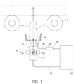
- FIG. 1 is a diagram schematically illustrating an ultrasonic testing apparatus according to a first exemplary embodiment
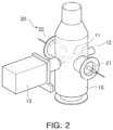
- FIG. 2 is a perspective view illustrating a main part of the ultrasonic testing apparatus according to said first exemplary embodiment
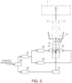
- FIG. 3 is a diagram for describing a control process of the ultrasonic testing apparatus according to said first exemplary embodiment.
- the ultrasonic testing apparatus includes a nozzle 10 and a plurality of probes 20, 21, and 22.
- the nozzle 10 may be installed on a lower side of an object 1 such as a thick steel plate conveyed by a conveyance means, for example, a guide roll 3, and jet a medium 2 (for example, water) toward the object to form a medium column 4 (for example, a water column).
- a conveyance means for example, a guide roll 3
- a medium 2 for example, water
- a medium column 4 for example, a water column
- Such a nozzle 10 should be able to form a stable medium column 4 in close contact with a lower surface of the object 1. To this end, an inner diameter of the nozzle is limited.
- the relationship between an inner diameter d of the nozzle 10 and a width w or diameter of a probe surface needs to satisfy the following [Equation 1].
- the probe surface refers to a surface on which the ultrasonic waves are substantially oscillated by the probe 20.
- frequency switching is possible using one nozzle 10 having the inner diameter d of a correlation as in the above Equation 1 with respect to the width w or diameter of the probe surface.
- the medium column 4 may be formed to have a height of several tens of millimeters (mm) from an outlet of the nozzle 10, and the transmission and reception of ultrasonic waves is possible through this medium column. Since water is employed as a medium having excellent ultrasonic transmission efficiency, the medium column may be formed of a water column.
- the ultrasonic testing apparatus may further include a medium circulation unit 30 that forms the medium column 4 by jetting the medium 2 from the nozzle 10, recovering the medium falling from the medium column, and circulating the medium back to the nozzle.
- a medium circulation unit 30 that forms the medium column 4 by jetting the medium 2 from the nozzle 10, recovering the medium falling from the medium column, and circulating the medium back to the nozzle.
- the medium circulation unit 30 may include a medium receiver 31, a recovery pipe 32, and a supply pipe 33.
- the medium receiver 31 may be installed outside the nozzle 10 and may be configured to receive the medium 2 that has fallen from the medium column 4.
- the medium receiver may be formed in a cylindrical shape or a box shape surrounding the nozzle.
- the recovery pipe 32 may be connected to the medium receiver 31 and may be configured to recover the medium 2 in the medium receiver.
- the medium falling from the medium column 4 and collected in the medium receiver may be supplied to the recovery pipe.
- a filter 34 for filtering the medium 2 discharged from the medium receiver 32 may be installed in the recovery pipe 32, so the medium from which impurities have been removed may be re-supplied to the nozzle 10.
- the supply pipe 33 is for supplying the medium 2 of the recovery pipe 32 to the nozzle 10, and may communicate with the nozzle 10 and the recovery pipe 32, respectively.
- a circulation pump 35 providing jetting pressure to the nozzle 10 may be installed between the recovery pipe 32 and the supply pipe 33.
- the medium column 4 may be formed by allowing the nozzle to jet the medium 2 at a constant pressure according to the pressure provided by the circulation pump. By controlling the circulation pump, the jetting pressure of the nozzle may be controlled.
- the plurality of probes 20 are disposed on the nozzle 10 to oscillate ultrasonic waves.
- each of the plurality of probes 20 may be fixedly installed to be spaced apart from each other on a sidewall of the nozzle 10, and may transmit and receive ultrasonic waves for detecting internal defects in the object 1 through the medium column 4.
- FIGS. 1 to 3 illustrate an example in which two probes 21 and 22 are mounted symmetrically with respect to the nozzle.
- the plurality of probes 20 oscillate ultrasonic waves having different frequencies.
- one probe 21 may oscillate an ultrasonic wave having a frequency of about 5 MHz
- the other probe 22 may oscillate an ultrasonic wave having a frequency of about 2 MHz.
- Each of these probes 20 may be connected to, through wired and wireless communication, a defect detection unit (not illustrated) that processes and calculates an ultrasonic signal received from the object 1 to analyze whether internal defects are present in an object.
- a defect detection unit not illustrated
- the ultrasonic testing apparatus includes an ultrasonic reflector 11 that is rotatably installed between the plurality of probes in the nozzle so that an ultrasonic wave of a probe selected from the plurality of probes 20 is transmitted to the object 1.
- the ultrasonic reflector 11 may be made of, for example, a metal material such as stainless steel and brass, and thus, may smoothly reflect ultrasonic waves, and may not be corroded by the medium 2 such as water.
- the ultrasonic reflector 11 is fixed to a rotation shaft 12 installed across the inside of the nozzle 10, and the rotation shaft may be exposed to the outside through a sidewall of the nozzle 10.
- a motor 13 installed outside the nozzle is connected to one end of the rotation shaft, so a rotation angle of the ultrasonic reflector may be controlled.
- the rotation angle may be controlled by the motor 13, so the ultrasonic reflector 11 may selectively transmit ultrasonic waves oscillated from both probes 20 toward the object 1.
- a control process for automatically switching a frequency of an ultrasonic wave in the ultrasonic testing apparatus according to the first exemplary embodiment will be described with reference to FIG. 3 .
- a product which is the object 1 subjected to the ultrasonic testing is conveyed to the ultrasonic testing apparatus by the guide roll 3.
- a main controller 40 constituting a factory operation system may receive thickness information of the object.
- the main controller 40 may transmit the received thickness information to an on-off controller 41 for probe.
- the on-off controller 41 for probe selects one of the plurality of probes 20 based on the thickness information of the object 1 to be subjected to the ultrasonic testing according to its internal program.
- a command is transmitted to a first pulser receiver 43 corresponding to one probe 21 that oscillates an ultrasonic wave having a frequency of about 5 MHz to operate the first pulser receiver 43 and stop an operation of a second pulser receiver 44 of the other probe 22.
- a command is transmitted to the second pulser receiver 44 corresponding to the other probe 22 that oscillates an ultrasonic wave having a frequency of about 2 MHz to operate the second pulser receiver 44 and stop the operation of the first pulser receiver 43.
- the main controller 40 transmits the received thickness information to a direction controller 42 for an ultrasonic reflector.
- the direction controller 42 for the ultrasonic reflector controls a rotation angle of the ultrasonic reflector by operating the motor 13 according to the transmitted thickness information and switches an inclination direction of the ultrasonic reflector.
- the inclination direction of the ultrasonic reflector 11 so that an ultrasonic wave having a frequency of about 5 MHz oscillated from one probe 21 is reflected toward the outlet of the nozzle 10 and a lower surface of the object is changed.
- the inclination direction of the ultrasonic reflector 11 so that an ultrasonic wave having a frequency of about 2 MHz oscillated from the other probe 22 is reflected toward the outlet of the nozzle 10 and the lower surface of the object is changed.
- the plurality of probes 20 oscillating ultrasonic waves having different frequencies are symmetrically mounted on the nozzle 10, and by controlling the rotation angle of the ultrasonic reflector 11 located between the probes so that the ultrasonic wave of the selected frequency according to the thickness of the object 1 is transmitted to an object, the frequency of the ultrasonic wave may be automatically switched according to the thickness of the object.
- the ultrasonic testing apparatus it is possible to easily switch the frequency of the ultrasonic wave and to stably transmit/receive the ultrasonic wave.
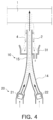
- FIG. 4 is a cross-sectional view illustrating a main part of an ultrasonic testing apparatus according to an embodiment which is not encompassed by the claims but is considered as useful for understanding the invention
- FIG. 5 is a diagram for describing a control process of the ultrasonic testing apparatus illustrated in FIG. 4 .
- FIGS. 4 and 5 is different from the first embodiment illustrated in FIGS. 1 to 3 described above in terms of only the shape of the nozzle without the ultrasonic reflector and the motor and the arrangement relationship of the probes, and the remaining components are the same as those of the first embodiment. Therefore, the same components as those of the ultrasonic testing apparatus according to the first embodiment will be denoted by the same reference numerals, and a detailed description for configurations and functions of these components will be omitted.
- the nozzle 10 may be formed of one outlet waveguide 15 and branched from the outlet waveguide, and the plurality of probes 20 may further include a plurality of inlet waveguides 14 distributed to each of the plurality of probes 20.
- Each of the plurality of probes 20 may be installed inside the corresponding inlet waveguide 14, and may transmit and receive ultrasonic waves for detecting internal defects in the object 1 through the medium column 4.
- these probes 20 may oscillate ultrasonic waves having different frequencies.
- one probe 21 may oscillate an ultrasonic wave having a frequency of about 5 MHz
- the other probe 22 may oscillate an ultrasonic wave having a frequency of about 2 MHz.
- Each of these probes 20 may be connected to, through wired and wireless communication, the defect detection unit (not illustrated) that processes and calculates the ultrasonic signal received from the object 1 to analyze whether the internal defects exist in the object.
- the defect detection unit (not illustrated) that processes and calculates the ultrasonic signal received from the object 1 to analyze whether the internal defects exist in the object.
- the ultrasonic waves oscillated from the probes 20 in each inlet waveguide 14 may be propagated out of the nozzle 10 through the outlet waveguide 15.
- the medium 2 may also be supplied to the inlet waveguide 14 through a branched supply pipe (not illustrated), and then may be jetted out of the nozzle 10 via the outlet waveguide 15 through a common path.
- the total reflection condition between the ultrasonic wave and the inner interface of the waveguide needs to be satisfied so that the ultrasonic wave introduced into the inlet waveguide 14 is propagated without loss in the outlet waveguide 15. That is, the loss of ultrasonic energy in the waveguide needs to be minimized.
- an ultrasonic velocity V 1 in the medium in the waveguide needs to be smaller than an ultrasonic velocity V 2 in the inner interface of the waveguide.
- Equation 2 may be satisfied when the medium 2 such as water is filled inside the waveguide, and the inlet waveguide 14 and the outlet waveguide 15 are made of a metal material.
- the inlet waveguide and the outlet waveguide are designed so that an angle (incident angle: ⁇ ) between a propagation direction of the ultrasonic wave traveling from the inlet waveguide to the outlet waveguide and a direction perpendicular to the inner interface of the outlet waveguide is greater than a critical angle ⁇ c, the ultrasonic waves may be transmitted through the outlet waveguide without loss.
- ⁇ C arcsin V 1 V 2
- one outlet waveguide 15 and the plurality of inlet waveguides 14 constituting the nozzle 10 may be designed under the condition satisfying the above Equations 2 and 3, and when the plurality of probes 20 selectively oscillate ultrasonic waves having different frequencies, the ultrasonic testing of the object 1 having various thicknesses becomes possible.
- a control process for automatically switching a frequency of an ultrasonic wave in the ultrasonic testing apparatus illustrated in FIG. 4 will be described with reference to FIG. 5 .
- the product which is the object 1 subjected to the ultrasonic testing is conveyed to the ultrasonic testing apparatus by the guide roll 3.
- the main controller 40 constituting the factory operation system may receive the thickness information of the object.
- the main controller 40 may transmit the received thickness information to the on-off controller 41 for probe.
- the on-off controller 41 for probe may select one of the plurality of probes 20 based on the thickness information of the object 1 to be subjected to the ultrasonic testing according to its internal program.
- a command is transmitted to the first pulser receiver 43 corresponding to one probe 21 that oscillates an ultrasonic wave having a frequency of about 5 MHz to operate the first pulser receiver 43 and stop the operation of the second pulser receiver 44 of the other probe 22.
- a command is transmitted to the second pulser receiver 44 corresponding to the other probe 22 that oscillates an ultrasonic wave having a frequency of about 2 MHz to operate the second pulser receiver 44 and stop the operation of the first pulser receiver 43.
- each of the probes 20 oscillating ultrasonic waves having different frequencies may be mounted on the plurality of inlet waveguides 14 of the nozzle 10, and the operation of the probe 20 may be selectively controlled so that the ultrasonic wave of the frequency selected according to the thickness of the object 1 is transmitted to the object through the outlet waveguide 15, so the frequency of the ultrasonic wave may be automatically switched according to the thickness of the object.
- the frequency of the ultrasonic wave may be automatically selected according to the thickness of the object and then the ultrasonic wave may be transmitted to the lower surface of the object through the nozzle, so the internal defects in objects having various thicknesses through one ultrasonic testing apparatus may be detected.
- the present invention is useful for ultrasonic testing performed on products that have been produced in a thick plate factory of a steel mill, for example.
Landscapes
- Physics & Mathematics (AREA)
- Chemical & Material Sciences (AREA)
- Health & Medical Sciences (AREA)
- Life Sciences & Earth Sciences (AREA)
- General Physics & Mathematics (AREA)
- Analytical Chemistry (AREA)
- Biochemistry (AREA)
- General Health & Medical Sciences (AREA)
- Immunology (AREA)
- Pathology (AREA)
- Acoustics & Sound (AREA)
- Engineering & Computer Science (AREA)
- Mechanical Engineering (AREA)
- Crystallography & Structural Chemistry (AREA)
- Food Science & Technology (AREA)
- Medicinal Chemistry (AREA)
- Multimedia (AREA)
- Investigating Or Analyzing Materials By The Use Of Ultrasonic Waves (AREA)
Claims (6)
- Ultraschallprüfgerät, umfassend:eine Düse (10), die ein Medium (2) in Richtung eines Objekts (1) ausstößt, um eine Mediensäule (4) zu bilden;eine Vielzahl von Sonden (20, 21, 22), die an der Düse (10) angeordnet sind, um eine Ultraschallwelle zu oszillieren, wobei die Vielzahl von Sonden (20, 21, 22) Ultraschallwellen, die unterschiedliche Frequenzen aufweisen, oszilliert;einen Ultraschallreflektor (11), der drehbar zwischen der Vielzahl von Sonden (20, 21, 22) in der Düse (10) installiert ist, so dass eine Ultraschallwelle einer Sonde, die aus der Vielzahl von Sonden (20, 21, 22) ausgewählt ist, an das Objekt (1) übertragen wird, wobei der Ultraschallreflektor (11) an einer Drehwelle (12), die über eine Innenseite der Düse (10) installiert ist, befestigt ist und ein Motor (13), der außerhalb der Düse (10) installiert ist, mit einem Ende der Drehwelle (12) verbunden ist;eine Hauptsteuerung (40), die Dickeninformationen des Objekts (1) empfängt;eine Ein-Aus-Steuerung (41) zum Auswählen einer Sonde aus der Vielzahl von Sonden (20, 21, 22) basierend auf den Dickeninformationen des Objekts (1), die von der Hauptsteuerung (40) übertragen werden;einen ersten Impulsgeberempfänger (43) und einen zweiten Impulsgeberempfänger (44), die selektiv eine Ultraschallwelle einer entsprechenden Sonde (21, 22) gemäß einem Befehl der Ein-Aus-Steuerung (41) für die Sonde oszillieren; undeine Richtungssteuerung (42) zum Steuern eines Drehwinkels des Ultraschallreflektors (11) durch Betreiben des Motors (13) basierend auf den Dickeninformationen des Objekts (1), die von der Hauptsteuerung (40) übertragen werden.
- Ultraschallprüfgerät nach Anspruch 1, wobei eine Beziehung zwischen einem Innendurchmesser d der Düse (10) und einer Breite w oder einem Durchmesser einer Sondenoberfläche einer Sonde in der folgenden Gleichung [Gleichung 1] hergestellt wird:

- Ultraschallprüfgerät nach Anspruch 1, wobei die Vielzahl von Sonden (20, 21, 22) fest installiert ist, um voneinander an einer Seitenwand der Düse (10) beabstandet zu sein.
- Ultraschallprüfgerät nach Anspruch 3, wobei der Ultraschallreflektor (11) ein Material umfasst, das Ultraschallwellen reflektiert und das nicht durch das Medium (2) korrodiert wird.
- Ultraschallprüfgerät nach einem der Ansprüche 1 bis 4, ferner umfassend:
eine Medienzirkulationseinheit (30), die eine Mediensäule (4) durch Ausstoßen des Mediums (2) aus der Düse (10), Rückgewinnen des Mediums (2), das aus der Mediensäule (4) fällt, und Zirkulieren des Mediums (2) zurück zu der Düse (10) bildet. - Ultraschallprüfgerät nach Anspruch 5, wobei die Medienzirkulationseinheit (30) Folgendes beinhaltet:einen Medienempfänger (31), der außerhalb der Düse (10) installiert ist und das Medium (2), das aus der Mediensäule (4) fällt, empfängt;ein Rückgewinnungsrohr (32), das mit dem Medienempfänger (31) verbunden ist;ein Zufuhrrohr (33), welches das Medium (2) des Rückgewinnungsrohrs der Düse (10) zuführt; undeine Zirkulationspumpe (35), die zwischen dem Rückgewinnungsrohr (32) und dem Zufuhrrohr (33) installiert ist, um der Düse (10) Ausstoßdruck bereitzustellen.
Applications Claiming Priority (2)
| Application Number | Priority Date | Filing Date | Title |
|---|---|---|---|
| KR1020190169360A KR102305732B1 (ko) | 2019-12-18 | 2019-12-18 | 주파수 가변형 초음파 탐상 장치 |
| PCT/KR2020/018399 WO2021125767A1 (ko) | 2019-12-18 | 2020-12-16 | 주파수 가변형 초음파 탐상 장치 |
Publications (4)
| Publication Number | Publication Date |
|---|---|
| EP4080205A1 EP4080205A1 (de) | 2022-10-26 |
| EP4080205A4 EP4080205A4 (de) | 2023-01-04 |
| EP4080205C0 EP4080205C0 (de) | 2024-11-20 |
| EP4080205B1 true EP4080205B1 (de) | 2024-11-20 |
Family
ID=76476694
Family Applications (1)
| Application Number | Title | Priority Date | Filing Date |
|---|---|---|---|
| EP20902050.2A Active EP4080205B1 (de) | 2019-12-18 | 2020-12-16 | Ultraschallprüfgerät mit variabler frequenz |
Country Status (6)
| Country | Link |
|---|---|
| US (1) | US12339254B2 (de) |
| EP (1) | EP4080205B1 (de) |
| JP (1) | JP7394225B2 (de) |
| KR (1) | KR102305732B1 (de) |
| CN (1) | CN114829924A (de) |
| WO (1) | WO2021125767A1 (de) |
Families Citing this family (4)
| Publication number | Priority date | Publication date | Assignee | Title |
|---|---|---|---|---|
| JP7734611B2 (ja) * | 2022-03-18 | 2025-09-05 | 株式会社日本製鋼所 | 超音波検査用スカーター |
| CN116008398A (zh) * | 2022-12-13 | 2023-04-25 | 之江实验室 | 一种超声扫描显微成像装置及方法 |
| US20250116598A1 (en) * | 2023-10-05 | 2025-04-10 | Kla Corporation | Enhanced modes for scanning acoustic microscope inspection in semiconductor inspection |
| CN120142482B (zh) * | 2025-05-15 | 2025-09-19 | 大唐吉林发电有限公司长山热电分公司 | 一种汽轮机叶片铸造加工后的超声波无损检测装置 |
Family Cites Families (28)
| Publication number | Priority date | Publication date | Assignee | Title |
|---|---|---|---|---|
| US3924454A (en) * | 1973-10-24 | 1975-12-09 | Automation Ind Inc | Multi-frequency ultrasonic testing system |
| US4599900A (en) * | 1984-01-03 | 1986-07-15 | Automation Industries, Inc. | Workpiece for handling apparatus for nondestructive testing |
| US4558598A (en) * | 1984-06-07 | 1985-12-17 | The Boeing Company | Ultrasonic linear array water nozzle and method |
| JPH0524052Y2 (de) | 1987-06-05 | 1993-06-18 | ||
| US5123433A (en) * | 1989-05-24 | 1992-06-23 | Westinghouse Electric Corp. | Ultrasonic flow nozzle cleaning apparatus |
| DE4026458A1 (de) | 1990-08-17 | 1992-02-20 | Mannesmann Ag | Us-pruefvorrichtung |
| DE4315794C2 (de) * | 1993-05-13 | 1995-09-21 | Nukem Gmbh | Verfahren und Vorrichtung zur zerstörungsfreien Prüfung von Gegenständen mit Ultraschall |
| US5494038A (en) * | 1995-04-25 | 1996-02-27 | Abbott Laboratories | Apparatus for ultrasound testing |
| JP3821435B2 (ja) * | 2002-10-18 | 2006-09-13 | 松下電器産業株式会社 | 超音波探触子 |
| JP2004271351A (ja) | 2003-03-10 | 2004-09-30 | Shoryo Denshi Kk | 探触子 |
| JP4576281B2 (ja) | 2005-04-15 | 2010-11-04 | 株式会社日立エンジニアリング・アンド・サービス | 超音波検査方法 |
| DE102005022729B4 (de) * | 2005-05-18 | 2022-01-20 | Baker Hughes Digital Solutions Gmbh | Verfahren und Prüfkopfanordnung zur Ankopplung von Ultraschallsignalen an ein zu prüfendes Bauteil mittels Wasserfreistrahltechnik |
| SG138524A1 (en) | 2006-06-22 | 2008-01-28 | Siltronic Ag | Method and apparatus for detection of mechanical defects in an ingot piece composed of semiconductor material |
| JP5419592B2 (ja) * | 2009-08-21 | 2014-02-19 | 三菱重工業株式会社 | 超音波検査用探触子および超音波検査装置 |
| KR101107154B1 (ko) * | 2009-09-03 | 2012-01-31 | 한국표준과학연구원 | 초음파 탐상장치의 멀티 탐촉자 유닛 |
| CN202676673U (zh) | 2012-08-03 | 2013-01-16 | 北京交通大学 | 钢管超声波探伤组合探头装置 |
| KR101414520B1 (ko) * | 2013-04-30 | 2014-07-04 | 한국과학기술원 | 비선형 초음파 모듈레이션 기법을 이용한 구조물의 무선 진단장치 및 그를 이용한 안전진단 방법 |
| KR101595492B1 (ko) * | 2013-12-26 | 2016-02-18 | 주식회사 포스코 | 강판 결함 검출을 위한 초음파 탐상 장치 |
| US10082487B2 (en) * | 2013-12-23 | 2018-09-25 | Posco | Apparatus and method for ultrasonic detection to detect flaws of steel plate |
| KR20150073566A (ko) * | 2013-12-23 | 2015-07-01 | 주식회사 포스코 | 강판 결함 검출을 위한 초음파 탐상 장치 및 방법 |
| JP5650339B1 (ja) * | 2014-02-06 | 2015-01-07 | 株式会社日立パワーソリューションズ | 超音波検査装置 |
| GB201417162D0 (en) * | 2014-09-29 | 2014-11-12 | Renishaw Plc | Inspection appartus |
| KR101739030B1 (ko) * | 2014-12-15 | 2017-05-23 | 주식회사 포스코 | 강판 결함 검출을 위한 초음파 탐상 장치 |
| US20180172644A1 (en) * | 2015-06-18 | 2018-06-21 | Socpra Sciences Et Génie S.E.C. | Method and system for acoustically scanning a sample |
| WO2017029598A1 (en) * | 2015-08-14 | 2017-02-23 | Eyelife As | Ultrasonic scanner with a multiple faceted mirror |
| KR101618158B1 (ko) | 2015-08-29 | 2016-05-04 | 엔디티엔지니어링(주) | 다채널 초음파 탐촉 장치 |
| KR101736612B1 (ko) * | 2015-12-07 | 2017-05-17 | 주식회사 포스코 | 높이 조절형 초음파 센서를 이용한 강판의 내부 결함 탐상 장치 및 방법 |
| WO2017200117A1 (ko) * | 2016-05-17 | 2017-11-23 | 한빛이디에스(주) | Saw소자를 이용한 무선 온도 측정 장치 |
-
2019
- 2019-12-18 KR KR1020190169360A patent/KR102305732B1/ko active Active
-
2020
- 2020-12-16 WO PCT/KR2020/018399 patent/WO2021125767A1/ko not_active Ceased
- 2020-12-16 JP JP2022536834A patent/JP7394225B2/ja active Active
- 2020-12-16 EP EP20902050.2A patent/EP4080205B1/de active Active
- 2020-12-16 US US17/779,579 patent/US12339254B2/en active Active
- 2020-12-16 CN CN202080087439.6A patent/CN114829924A/zh active Pending
Also Published As
| Publication number | Publication date |
|---|---|
| KR20210077884A (ko) | 2021-06-28 |
| JP2023507944A (ja) | 2023-02-28 |
| JP7394225B2 (ja) | 2023-12-07 |
| EP4080205C0 (de) | 2024-11-20 |
| KR102305732B1 (ko) | 2021-09-27 |
| US12339254B2 (en) | 2025-06-24 |
| WO2021125767A1 (ko) | 2021-06-24 |
| CN114829924A (zh) | 2022-07-29 |
| EP4080205A4 (de) | 2023-01-04 |
| EP4080205A1 (de) | 2022-10-26 |
| US20230009623A1 (en) | 2023-01-12 |
Similar Documents
| Publication | Publication Date | Title |
|---|---|---|
| EP4080205B1 (de) | Ultraschallprüfgerät mit variabler frequenz | |
| US8776604B2 (en) | Ultrasonic probe, ultrasonic testing equipment, and ultrasonic testing method | |
| US5942687A (en) | Method and apparatus for in situ measurement of corrosion in filled tanks | |
| CN102282463B (zh) | 焊接部的超声波探伤方法及装置 | |
| AU697833B2 (en) | Ultrasonic inspection | |
| EP0263475B1 (de) | Verfahren und Apparatur zum Ultraschallnachweis von Rissen | |
| KR100400184B1 (ko) | 원기둥체 표면의 초음파 탐상방법과 그 탐상장치및 이를 이용한 롤의 연삭방법 | |
| EP0164168B1 (de) | Verfahren und Wasserstrahldüse für eine lineare Ultraschall-Sondenanordnung | |
| CN101617222A (zh) | 管体的品质管理方法和制造方法 | |
| WO2007110900A1 (ja) | 欠陥検査装置及び欠陥検査方法 | |
| CN108291895A (zh) | 使用高度可调节的超声传感器的钢板内部瑕疵检测装置和方法 | |
| JP3671819B2 (ja) | 溶接鋼管の超音波探傷装置 | |
| JP2014077708A (ja) | 検査装置および検査方法 | |
| RU2592044C1 (ru) | Способ ультразвуковых измерений и ультразвуковое измерительное устройство | |
| KR870001259B1 (ko) | 전자주사를 이용하는 각 강편의 검사방법 | |
| KR101139592B1 (ko) | 접촉매질 막 유지를 위한 종파 탐촉자 웨지 및 이를 이용한 종파 탐촉자 | |
| JP2001050941A (ja) | 可変角超音波探触子及び可変角超音波探傷装置 | |
| EP3827255B1 (de) | Verfahren zur beurteilung des einschlussgrades bei stahlrohren unter verwendung eines hochfrequenzwandlers bei der automatischen ultraschallprüfung | |
| JP2003028845A (ja) | フェーズドアレイによる探傷方法及び探傷装置 | |
| JPH04256852A (ja) | 薄板の超音波探傷方法 | |
| JPH06258294A (ja) | 超音波探傷装置 | |
| HK40046649A (en) | Method for assessing inclusive level in steel tubes using high frequency transducer in the automatic ultrasound inspection | |
| JP2001318083A (ja) | 超音波探傷装置および超音波探傷方法 | |
| JPH11133005A (ja) | ロール検査用表面波プローブとその入射角設定方法 | |
| KR20080110874A (ko) | 초음파 탐촉자, 초음파 탐상 방법 및 초음파 탐상 장치 |
Legal Events
| Date | Code | Title | Description |
|---|---|---|---|
| STAA | Information on the status of an ep patent application or granted ep patent |
Free format text: STATUS: THE INTERNATIONAL PUBLICATION HAS BEEN MADE |
|
| PUAI | Public reference made under article 153(3) epc to a published international application that has entered the european phase |
Free format text: ORIGINAL CODE: 0009012 |
|
| STAA | Information on the status of an ep patent application or granted ep patent |
Free format text: STATUS: REQUEST FOR EXAMINATION WAS MADE |
|
| 17P | Request for examination filed |
Effective date: 20220705 |
|
| AK | Designated contracting states |
Kind code of ref document: A1 Designated state(s): AL AT BE BG CH CY CZ DE DK EE ES FI FR GB GR HR HU IE IS IT LI LT LU LV MC MK MT NL NO PL PT RO RS SE SI SK SM TR |
|
| A4 | Supplementary search report drawn up and despatched |
Effective date: 20221202 |
|
| RIC1 | Information provided on ipc code assigned before grant |
Ipc: G10K 11/35 20060101ALI20221128BHEP Ipc: G01N 29/22 20060101ALI20221128BHEP Ipc: G01N 29/27 20060101ALI20221128BHEP Ipc: G01N 29/24 20060101ALI20221128BHEP Ipc: G01N 29/04 20060101AFI20221128BHEP |
|
| DAV | Request for validation of the european patent (deleted) | ||
| DAX | Request for extension of the european patent (deleted) | ||
| GRAP | Despatch of communication of intention to grant a patent |
Free format text: ORIGINAL CODE: EPIDOSNIGR1 |
|
| STAA | Information on the status of an ep patent application or granted ep patent |
Free format text: STATUS: GRANT OF PATENT IS INTENDED |
|
| INTG | Intention to grant announced |
Effective date: 20240625 |
|
| GRAS | Grant fee paid |
Free format text: ORIGINAL CODE: EPIDOSNIGR3 |
|
| GRAA | (expected) grant |
Free format text: ORIGINAL CODE: 0009210 |
|
| STAA | Information on the status of an ep patent application or granted ep patent |
Free format text: STATUS: THE PATENT HAS BEEN GRANTED |
|
| AK | Designated contracting states |
Kind code of ref document: B1 Designated state(s): AL AT BE BG CH CY CZ DE DK EE ES FI FR GB GR HR HU IE IS IT LI LT LU LV MC MK MT NL NO PL PT RO RS SE SI SK SM TR |
|
| REG | Reference to a national code |
Ref country code: GB Ref legal event code: FG4D |
|
| REG | Reference to a national code |
Ref country code: CH Ref legal event code: EP |
|
| REG | Reference to a national code |
Ref country code: DE Ref legal event code: R096 Ref document number: 602020041863 Country of ref document: DE |
|
| REG | Reference to a national code |
Ref country code: IE Ref legal event code: FG4D |
|
| U01 | Request for unitary effect filed |
Effective date: 20241209 |
|
| U07 | Unitary effect registered |
Designated state(s): AT BE BG DE DK EE FI FR IT LT LU LV MT NL PT RO SE SI Effective date: 20241219 |
|
| U20 | Renewal fee for the european patent with unitary effect paid |
Year of fee payment: 5 Effective date: 20241230 |
|
| PG25 | Lapsed in a contracting state [announced via postgrant information from national office to epo] |
Ref country code: IS Free format text: LAPSE BECAUSE OF FAILURE TO SUBMIT A TRANSLATION OF THE DESCRIPTION OR TO PAY THE FEE WITHIN THE PRESCRIBED TIME-LIMIT Effective date: 20250320 Ref country code: HR Free format text: LAPSE BECAUSE OF FAILURE TO SUBMIT A TRANSLATION OF THE DESCRIPTION OR TO PAY THE FEE WITHIN THE PRESCRIBED TIME-LIMIT Effective date: 20241120 |
|
| PG25 | Lapsed in a contracting state [announced via postgrant information from national office to epo] |
Ref country code: ES Free format text: LAPSE BECAUSE OF FAILURE TO SUBMIT A TRANSLATION OF THE DESCRIPTION OR TO PAY THE FEE WITHIN THE PRESCRIBED TIME-LIMIT Effective date: 20241120 |
|
| PG25 | Lapsed in a contracting state [announced via postgrant information from national office to epo] |
Ref country code: NO Free format text: LAPSE BECAUSE OF FAILURE TO SUBMIT A TRANSLATION OF THE DESCRIPTION OR TO PAY THE FEE WITHIN THE PRESCRIBED TIME-LIMIT Effective date: 20250220 |
|
| PG25 | Lapsed in a contracting state [announced via postgrant information from national office to epo] |
Ref country code: GR Free format text: LAPSE BECAUSE OF FAILURE TO SUBMIT A TRANSLATION OF THE DESCRIPTION OR TO PAY THE FEE WITHIN THE PRESCRIBED TIME-LIMIT Effective date: 20250221 |
|
| PG25 | Lapsed in a contracting state [announced via postgrant information from national office to epo] |
Ref country code: PL Free format text: LAPSE BECAUSE OF FAILURE TO SUBMIT A TRANSLATION OF THE DESCRIPTION OR TO PAY THE FEE WITHIN THE PRESCRIBED TIME-LIMIT Effective date: 20241120 |
|
| PG25 | Lapsed in a contracting state [announced via postgrant information from national office to epo] |
Ref country code: RS Free format text: LAPSE BECAUSE OF FAILURE TO SUBMIT A TRANSLATION OF THE DESCRIPTION OR TO PAY THE FEE WITHIN THE PRESCRIBED TIME-LIMIT Effective date: 20250220 |
|
| PG25 | Lapsed in a contracting state [announced via postgrant information from national office to epo] |
Ref country code: SM Free format text: LAPSE BECAUSE OF FAILURE TO SUBMIT A TRANSLATION OF THE DESCRIPTION OR TO PAY THE FEE WITHIN THE PRESCRIBED TIME-LIMIT Effective date: 20241120 |
|
| PG25 | Lapsed in a contracting state [announced via postgrant information from national office to epo] |
Ref country code: SK Free format text: LAPSE BECAUSE OF FAILURE TO SUBMIT A TRANSLATION OF THE DESCRIPTION OR TO PAY THE FEE WITHIN THE PRESCRIBED TIME-LIMIT Effective date: 20241120 |
|
| PG25 | Lapsed in a contracting state [announced via postgrant information from national office to epo] |
Ref country code: CZ Free format text: LAPSE BECAUSE OF FAILURE TO SUBMIT A TRANSLATION OF THE DESCRIPTION OR TO PAY THE FEE WITHIN THE PRESCRIBED TIME-LIMIT Effective date: 20241120 |
|
| REG | Reference to a national code |
Ref country code: CH Ref legal event code: PL |
|
| PG25 | Lapsed in a contracting state [announced via postgrant information from national office to epo] |
Ref country code: MC Free format text: LAPSE BECAUSE OF FAILURE TO SUBMIT A TRANSLATION OF THE DESCRIPTION OR TO PAY THE FEE WITHIN THE PRESCRIBED TIME-LIMIT Effective date: 20241120 |
|
| PLBE | No opposition filed within time limit |
Free format text: ORIGINAL CODE: 0009261 |
|
| STAA | Information on the status of an ep patent application or granted ep patent |
Free format text: STATUS: NO OPPOSITION FILED WITHIN TIME LIMIT |
|
| PG25 | Lapsed in a contracting state [announced via postgrant information from national office to epo] |
Ref country code: CH Free format text: LAPSE BECAUSE OF NON-PAYMENT OF DUE FEES Effective date: 20241231 |
|
| 26N | No opposition filed |
Effective date: 20250821 |
|
| PG25 | Lapsed in a contracting state [announced via postgrant information from national office to epo] |
Ref country code: IE Free format text: LAPSE BECAUSE OF NON-PAYMENT OF DUE FEES Effective date: 20241216 |
|
| GBPC | Gb: european patent ceased through non-payment of renewal fee |
Effective date: 20250220 |