EP4077903B1 - Schubumkehrer mit knickschutzbetätigungssystem - Google Patents
Schubumkehrer mit knickschutzbetätigungssystem Download PDFInfo
- Publication number
- EP4077903B1 EP4077903B1 EP20845594.9A EP20845594A EP4077903B1 EP 4077903 B1 EP4077903 B1 EP 4077903B1 EP 20845594 A EP20845594 A EP 20845594A EP 4077903 B1 EP4077903 B1 EP 4077903B1
- Authority
- EP
- European Patent Office
- Prior art keywords
- actuator
- thrust reverser
- fixed structure
- pin
- connection
- Prior art date
- Legal status (The legal status is an assumption and is not a legal conclusion. Google has not performed a legal analysis and makes no representation as to the accuracy of the status listed.)
- Active
Links
Images




Classifications
-
- F—MECHANICAL ENGINEERING; LIGHTING; HEATING; WEAPONS; BLASTING
- F02—COMBUSTION ENGINES; HOT-GAS OR COMBUSTION-PRODUCT ENGINE PLANTS
- F02K—JET-PROPULSION PLANTS
- F02K1/00—Plants characterised by the form or arrangement of the jet pipe or nozzle; Jet pipes or nozzles peculiar thereto
- F02K1/54—Nozzles having means for reversing jet thrust
- F02K1/76—Control or regulation of thrust reversers
- F02K1/763—Control or regulation of thrust reversers with actuating systems or actuating devices; Arrangement of actuators for thrust reversers
-
- F—MECHANICAL ENGINEERING; LIGHTING; HEATING; WEAPONS; BLASTING
- F02—COMBUSTION ENGINES; HOT-GAS OR COMBUSTION-PRODUCT ENGINE PLANTS
- F02K—JET-PROPULSION PLANTS
- F02K1/00—Plants characterised by the form or arrangement of the jet pipe or nozzle; Jet pipes or nozzles peculiar thereto
- F02K1/54—Nozzles having means for reversing jet thrust
- F02K1/64—Reversing fan flow
- F02K1/70—Reversing fan flow using thrust reverser flaps or doors mounted on the fan housing
- F02K1/72—Reversing fan flow using thrust reverser flaps or doors mounted on the fan housing the aft end of the fan housing being movable to uncover openings in the fan housing for the reversed flow
-
- F—MECHANICAL ENGINEERING; LIGHTING; HEATING; WEAPONS; BLASTING
- F05—INDEXING SCHEMES RELATING TO ENGINES OR PUMPS IN VARIOUS SUBCLASSES OF CLASSES F01-F04
- F05D—INDEXING SCHEME FOR ASPECTS RELATING TO NON-POSITIVE-DISPLACEMENT MACHINES OR ENGINES, GAS-TURBINES OR JET-PROPULSION PLANTS
- F05D2260/00—Function
- F05D2260/94—Functionality given by mechanical stress related aspects such as low cycle fatigue [LCF] of high cycle fatigue [HCF]
- F05D2260/941—Functionality given by mechanical stress related aspects such as low cycle fatigue [LCF] of high cycle fatigue [HCF] particularly aimed at mechanical or thermal stress reduction
-
- Y—GENERAL TAGGING OF NEW TECHNOLOGICAL DEVELOPMENTS; GENERAL TAGGING OF CROSS-SECTIONAL TECHNOLOGIES SPANNING OVER SEVERAL SECTIONS OF THE IPC; TECHNICAL SUBJECTS COVERED BY FORMER USPC CROSS-REFERENCE ART COLLECTIONS [XRACs] AND DIGESTS
- Y02—TECHNOLOGIES OR APPLICATIONS FOR MITIGATION OR ADAPTATION AGAINST CLIMATE CHANGE
- Y02T—CLIMATE CHANGE MITIGATION TECHNOLOGIES RELATED TO TRANSPORTATION
- Y02T50/00—Aeronautics or air transport
- Y02T50/60—Efficient propulsion technologies, e.g. for aircraft
Definitions
- the present invention relates to a turbojet nacelle comprising a thrust reverser intended to equip such a nacelle.
- a nacelle generally has a tubular structure comprising an air inlet upstream of the turbojet, a middle section intended to surround a fan of the turbojet, a downstream section housing thrust reversal means and intended to surround the combustion chamber of the turbojet, and is generally terminated by an ejection nozzle whose outlet is located downstream of the turbojet.
- Modern nacelles are designed to house a turbofan engine capable of generating, through the rotating fan blades, a hot primary airflow from the turbofan combustion chamber, and a secondary cold airflow that circulates outside the turbofan engine through an annular passage, also called an air stream, formed between a turbofan fairing and an internal wall of the nacelle. Both airflows are ejected from the turbofan engine through the rear of the nacelle.
- the role of a thrust reverser is, when an aircraft is landing, to improve its braking capacity by redirecting at least part of the thrust generated by the turbojet engine forward.
- the thrust reverser obstructs the cold flow stream and directs it towards the front of the nacelle, thereby generating counter-thrust which adds to the braking of the aircraft's wheels.
- the structure of an inverter comprises a fixed structure and a mobile structure movable between, on the one hand, a deployed position, called reverse jet, in which it opens a passage in the nacelle intended for the diverted flow, and on the other hand, a retracted position, called direct jet, in which it closes this passage.
- This mobile structure can fulfill a diversion function or simply activate other diversion means.
- the movable cowl is subjected to longitudinal and radial direction forces taken up by the fixed structure via the actuators.
- each actuator is linearly elongated to accompany the movement of the movable cowl.
- a blockage of the thrust reverser may occur at the actuators or at the rails and slides between the fixed structure and the movable structure.
- Such a blockage of the thrust reverser results in a blockage of the linear elongation of the actuators.
- the energy applied to the reverser causes a bending moment that can radially deform, relative to their axis, the actuators thus subjected to buckling.
- the document FR 2 978 800 A1 discloses a nacelle comprising a thrust reverser as described above and where the movable cowl is moved in translation by means of linear actuators ensuring both the movement of the movable cowl and the deployment or retraction of the thrust reverser flaps.
- each actuator also passes through an opening formed in a rear frame of the fixed structure.
- the opening of the rear frame of the fixed structure allows the radial displacement of the actuator to be limited relative to its axis, this does not prevent the degradation of the actuator or the propagation of mechanical vibrations generated by repeated contact between it and the fixed structure.
- this architecture requires the rear frame structure to be sized to allow the integration of the actuators.
- the document FR 2907 512 A1 proposes to limit the phenomenon of bending of the actuator using a slide secured to the mobile structure and accompanying the guide of a drive rod of the actuator relative to a body of the actuator.
- thrust reversers are known such as the one in the document US 2017/226962 A1 for example and other actuation systems are known such as that of the US 2010/089029 A1 For example.
- the aim of the invention is to propose a thrust reverser for a turbojet aircraft nacelle comprising a system for limiting the movement of the actuators having simplified integration while allowing a reduction in the drag and mass of the reverser.
- the configuration of the thrust reverser according to the invention makes it possible to limit the displacement of the actuator radially relative to its axis so that the bending moment applied to the actuator about an axis perpendicular to its main axis is greatly reduced.
- the use of a third connection between the actuator and the fixed structure which is offset relative to the main axis of the actuator allows the absorption by this connection of a large part of the forces transmitted from the mobile structure to the fixed structure via the actuator. This makes it possible to avoid oversizing the actuator structure, and thus avoid taking up mass and increasing the cost of the actuators.
- this solution makes it possible to standardize the use of a greater number of applications for the same actuator and therefore to promote the concept of product families.
- the offset of the axis of the third link relative to the axis of the actuator makes it easier to integrate this third link.
- the invention makes it easier to assemble and disassemble the actuator, unlike the known prior art in which the actuator passes through an opening.
- the main axis can be defined by a straight line connecting the first link and the second link.
- connection forms a system for limiting the radial movement of the actuator relative to its main axis.
- the third connection allows the actuator to move radially relative to the axis of the third connection.
- the predetermined displacement advantageously corresponds to a radial displacement of the actuator relative to the axis of the third connection over a maximum distance corresponding to 25% of the external diameter of the actuator.
- the third connection comprises complementary connection elements between the actuator and the fixed structure.
- the complementary connection elements are configured to allow the predetermined movement.
- the complementary connection element of the fixed structure is carried by a deflection means or a support structure of the deflection means.
- the deflection means is fixed relative to the fixed structure, such as a fixed deflection grid.
- a rear frame structure of the deflection means is preferably used as a support structure for the complementary connection element of the fixed structure.
- the complementary connection element of the fixed structure is carried by an external structure of the fixed structure.
- the deflection means is movable relative to the fixed structure, like a movable deflection grid.
- the external structure carrying the complementary connection element of the fixed structure may preferably be a fan casing of the external structure.
- the external structure carrying the complementary connection element of the fixed structure may be a deflection edge of the external structure.
- the complementary connection elements comprise a pin and an opening, the pin being at least partly housed in the opening.
- the pawn can be integrated or attached to the corresponding complementary element.
- connection formed by the pin and the opening allows circumscribed mobility of the actuator relative to the fixed structure, thus authorizing the predetermined movement.
- the pin and the opening form, between them, a multidirectional radial stop limiting the radial displacement of the actuator relative to its main axis. It is thus possible to resume the radial displacement relative to the main axis regardless of the direction, thus limiting the buckling of the actuator.
- the pin can be oriented parallel to the main axis of the actuator.
- the pin can be oriented downstream or upstream of the inverter.
- the predetermined displacement then corresponds to a radial displacement of the actuator relative to the axis of the third link, the main axis being able to be moved parallel or non-parallel relative to the axis of the third link.
- the complementary connection element of the fixed structure comprises the opening and the complementary connection element of the actuator comprises the pin.
- the axis of the third connection passes through the center of the opening.
- the complementary connection element of the fixed structure comprises the pin and the complementary connection element of the actuator comprises the opening.
- the axis of the third connection passes through the center of the pin.
- a radial clearance is formed between the opening and the pawn.
- the radial clearance between the opening and the pawn then corresponds to the predetermined displacement.
- the opening and the pin are tightly fitted.
- An elastic shock absorber can be positioned between the opening and the pin.
- the elastic shock absorber allows the absorption of mechanical stresses transmitted from the mobile structure to the fixed structure.
- the elastic properties of the damper allow movement in the connection between the opening and the pin corresponding to the predetermined displacement.
- the axis of the opening and the axis of the pin are eccentric relative to each other.
- the eccentric axes of the opening and the pin advantageously make it possible to constrain the predetermined movement in a given direction.
- the actuator comprises a body and a rod, the rod being guided by the body, the complementary connection element of the actuator being carried by the body of the actuator.
- the outside diameter of the actuator is determined by the cylinder body.
- the complementary connection element of the actuator is carried at the end of the actuator body from which the rod extends.
- the complementary connection elements of the fixed structure and of the actuator respectively comprise a flat surface spaced apart by an axial clearance.
- the axial clearance prevents the transmission of axial forces transmitted from the mobile structure to the fixed structure via the third connection of the actuator.
- planar surfaces of the fixed structure and the actuator comprise the opening and the pin.
- the flat surface of the complementary connection element of the actuator is formed by a projection of the body of the actuator.
- the flat surface of the complementary connection element of the fixed structure is formed by a radial wall.
- the projection and the radial wall together carry the opening and the pin.
- the flat surface of the complementary connection element of the actuator is formed by two projections extending from the body of the actuator and the flat surface of the complementary connection element of the fixed structure is formed by two protuberances corresponding to said projections.
- each projection and its complementary protuberance carry an opening and a pin.
- the two protuberances of said radial wall delimit between them a hollow rounded shape.
- the hollow rounded shape allows the actuator to be integrated at least in part with the complementary connection element of the fixed structure. Such integration allows a reduction in the size of the thrust reverser, thereby reducing the drag and mass of the reverser.
- the complementary connection element of the fixed structure can be advantageously integrated into the fixed structure.
- the complementary connection element of the fixed structure is formed by an angle iron.
- the present invention also relates to an aircraft nacelle comprising such a thrust reverser.
- radial will be understood to mean a radial direction relative to a longitudinal axis of the nacelle.
- axial will be understood to mean an axial direction according to the longitudinal direction of the nacelle.
- upstream and front will be used interchangeably to designate the upstream of the thrust reverser and the terms “downstream” and “rear” will be used interchangeably to designate the downstream of the thrust reverser.
- upstream and downstream refer to the direction of airflow into and out of a nacelle.
- a nacelle is intended to constitute a tubular housing for a dual-flow turbojet engine and is used to channel the air flows that it generates via the blades of a fan, namely a hot air flow (called the main flow) passing through a combustion chamber and a cold air flow (called the secondary flow) circulating outside the turbojet engine.
- This nacelle comprises an upstream section forming an air inlet, a middle section surrounding the turbojet fan and a downstream section 1 extending the middle section and surrounding the turbojet. Shown on the figure 1 , the part of the downstream section 1 of a nacelle known from the prior art.
- the downstream section 1 comprises a nacelle thrust reverser, here shown in an inverted jet configuration.
- the downstream section 1 comprises a fixed structure 10 and a movable structure 11.
- the mobile structure 11 comprises a mobile cover 13, reversing flaps 14.
- Flow deflection means 15 are shown, composed of an assembly of deflection grids 15 fixed relative to the fixed structure 10.
- the mobile structure 11 ends with an ejection nozzle section 16.
- the fixed structure 10 comprises an external structure 10a and an internal structure 10b of the engine fairing defining with the external structure 10a and the movable cowl a vein 20 intended for the circulation of the cold air flow or secondary flow, illustrated by the arrow F, in the case of the dual-flow turbojet nacelle as presented here.
- the external structure 10a further comprises a front frame structure 17 and a rear frame structure 18 ensuring the support of the deflection means 15 to the fixed structure 10 of the thrust reverser.
- the front frame structure 17 and the rear frame structure 18 are each attached to the external structure 10a of the fixed structure 10.
- the movable cowl 13 is intended to be actuated in a longitudinal direction of the nacelle between two extreme positions, namely a closed position, called the direct jet position, in which the movable cowl 13 comes into contact with the external structure 10a and where the reversing flaps 14 are retracted to ensure the aerodynamic continuity of the external lines of the downstream section 1 allowing the circulation of the secondary flow F in the vein 20; and an open position shown in figure 1 , called the reverse jet position, in which it opens a passage in the nacelle, obstructs the vein 20 using the deployed reversing flap 14 and uncovers the deflection means 15.
- the reverse jet position of the movable cowl allows the secondary flow F of the turbojet to escape at least partially, this portion of flow called deflected flow, illustrated by the arrow F1 being reoriented towards the front of the nacelle by the deflection grids 15, thereby generating a counter-thrust capable of assisting in the braking of the aircraft.
- the deployment of the mobile structure 11 is carried out by a set of actuators 2 here represented schematically by the main axis A1 of the actuator 2 actuating the longitudinal movement of the mobile structure 11 guided relative to the fixed structure 10 by means of a rail/slider system (not shown).
- the actuator 2 thus ensures the management of the thrust reversal by controlling the mobile structure 11 comprising the mobile cowl 13.
- Each actuator 2 is connected, on the one hand, by a first fixed connection P1 to the fixed structure 10, here the front frame structure 17 and, on the other hand, by a second fixed connection P2 to the mobile structure 11.
- the actuator 2 passes through an opening formed in the rear frame structure 18.
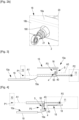
- FIG. 2a partly represents the rear frame structure 18 taking the form of a circular ring in which openings 180 are formed through which the actuators 2 pass through the rear frame structure 18.
- FIG. 2b illustrates in more detail the rear frame structure 18 comprising an axial wall 18a, as well as a radial wall 18b joined to each other.
- the openings 180 are formed on the radial wall 18b of the rear frame structure 18.
- FIG. 2b also illustrates the mounting of an actuator 2 through such an opening 180 of the rear frame structure 18.
- the actuator 2 comprises a hollow body 20 inside which is housed a rod 21 movable in translation.
- the hollow body 20 is attached at its upstream end to the front frame structure 17 by the first connection P1, while the rod 21 is connected at its free downstream end to the movable structure 11 by the second connection P2.
- the rod 21 thus passes through the rear frame structure 18, to be fixed to the movable structure 11.
- this solution makes it possible to limit the buckling of the actuator 2, it has the disadvantage of complex integration with the fixed structure 10, more particularly with its rear frame structure 18. In a configuration of particularly fine aerodynamic lines, this rear frame solution is not feasible, given its size.
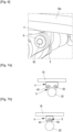
- the invention illustrated by the embodiments in Figures 3 and 4 allows, among other things, to simplify the integration of the actuator 2 into the fixed structure 10 while limiting the risks of buckling of the actuator 2.
- FIG 3 illustrates an implementation of the invention applied to a thrust reverser 1 whose deflection means are fixed, such as fixed deflection grids.
- the illustration of the embodiment of the figure 3 has been simplified to better represent the invention.
- the external fixed structure 10a comprising a fan casing 19 ending in a deflection edge 19a and the rear frame structure 18 have been partially represented.
- the body 20 of the actuator 2 is connected to the fixed structure 10 by the first connection P1 while the rod 21 is connected to the mobile structure 11 by the second connection P2.
- the actuator 2 extends along the main axis A1 coaxial with the hollow body 20 and the rod 21.
- a third connection P3 is provided between the actuator 2 and the fixed structure 10. This third connection P3 is arranged longitudinally between the first connection P1 and the second connection P2.
- the axis A3 of the third link P3 is radially eccentric relative to the main axis A1.
- the axis A3 of the third link P3 is chosen as a fixed axis relative to the fixed structure 10.
- This third connection P3 is provided to allow a predetermined displacement, in a radial direction relative to the axis A3, of the actuator 2 relative to the fixed structure 10. This predetermined displacement makes it possible to restrict the amplitude of movement of the actuator 2 when the latter is subjected to a buckling phenomenon.
- the third connection P3 is provided to allow the main axis A1 of the actuator 2 and the actuator 2 to move radially relative to the axis of the third connection A3.
- the third connection P3 comprises complementary connection elements 4, 5 between the actuator 2 and the fixed structure 10 to ensure the predetermined movement.
- the complementary connection elements 4, 5 comprise an opening 40 and a pin 50, the pin 50 being at least partly housed in the opening 40.
- the connection formed by the pin 50 and the opening 40 allows a circumscribed mobility of the actuator 2 relative to the fixed structure 10 thus authorizing the predetermined movement. In other words, the movement of the actuator 2 is circumscribed radially relative to the axis of the third connection A3.
- the complementary connection element 4 of the fixed structure 10 is carried by a support structure, here the rear frame structure 18, of the fixed deflection means 15 and the complementary connection element 5 of the actuator 2 is carried by the body 20 of the actuator 2.
- the complementary connection element 4 of the fixed structure 10 is formed by an angle iron from which the pin 50 extends and the complementary connection element 5 of the actuator 2 is formed by a projection of the body 20 comprising the opening 40.
- FIG 4 illustrates an implementation of the invention applied to a thrust reverser 1 whose deflection means are mobile, such as mobile deflection grids.
- the illustration of the embodiment of the figure 4 has also been simplified to better represent the invention.
- the deflection means 15 are deflection grids 15 movable relative to the fixed structure 10.
- the deflection grids are carried by the movable structure 11.
- the rear frame structure 18 is then fixed relative to the movable structure 11 and can entirely carry the deflection means 15.
- the complementary connection elements 4, 5 shown in the figure 4 are similar to those of the figure 3 .
- the complementary connection element 4 of the fixed structure 10 is carried by the external structure 10a, here the deflection edge 19a of the fixed structure 10 or alternatively the fan casing 19.
- connection P3 will be described in more detail as applied to the case of a thrust reverser 10 with fixed grids such as that illustrated in FIG. figure 3 .
- the characteristics described below also apply to a thrust reverser 10 with moving grids.
- FIG. figure 5a an upstream view of an embodiment similar to the embodiment shown in FIG. figure 3 .
- the complementary connection element 4 of the fixed structure 10 comprises the pin 50 and the complementary connection element 5 of the actuator 2 comprises the opening 40.
- the complementary connection element 4 of the fixed structure 10 or angle iron 4 comprises an axial wall 41 extended by a radial wall 42.
- the axial wall 41 is fixedly mounted on the rear frame structure 18, for example by welding.
- the complementary connection element of the actuator 2 or projection 5 takes the form of an ear 5.
- the radial wall 42 and the ear 5 respectively comprise a flat surface 42', 5' spaced apart by an axial clearance 9.
- Such axial clearance makes it possible to avoid the transmission of axial forces from the mobile structure 11 to the fixed structure 10 via the third connection P3 of the actuator 2.
- These same flat surfaces 42', 5' carry the opening 40 and the pin 50.
- the flat surface 42' of the complementary connection element 4 of the fixed structure 10 carries the pin 50 and the flat surface 5' of the complementary connection element 5 of the actuator 2 carries the opening 40.
- FIGS. 5b And 5c represent different views of the embodiment of the Figure 5a .
- FIG. 5b furthermore represents the second fixed connection P2 between the rod 21 of the actuator 2 and the mobile structure 11.
- the flat surface 5' of the complementary connection element 5 of the actuator 2 comprises two ear-shaped projections 5 extending from the body 20 of the actuator 2. These projections 5 may be spaced apart by an angle of less than 180°.
- the flat surface 42' of the complementary connection element 4 of the fixed structure 10 is formed by two protuberances 4 in correspondence with said protuberances 5.
- the two protuberances 4 of the radial wall 42 delimit between them a hollow rounded shape 43 which allows simplified integration at least in part of the actuator with the complementary connection element of the fixed structure. Such integration allows a reduction in the size of the thrust reverser, thus reducing the drag and the mass of the reverser.
- each projection 5 and its complementary protuberance 4 carry an opening 40 and a pin 50.
- FIG. 5d illustrates an enlargement of the third P3 bond shown in Figure 5a where a radial clearance 7 formed between the opening 40 and the pin 50 is shown. The clearance between the opening and the pin then corresponds to the predetermined displacement.
- opening 40 and pin 50 are tight fitting.
- an elastic shock absorber 8 may be provided between the opening 40 and the pin 50 to allow the absorption of mechanical stresses transmitted from the mobile structure 11 to the fixed structure 10.
- the shock absorber is here formed by an elastic ring housed in the opening 40 and surrounding the pin 50.
- the elastic damper 8 may be attached to or integrated into the opening 40 or the pin 50.
- the damper 8 may be provided to ensure a tight fit between the opening 40 and the pin 50.
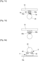
- FIGS. 7a to 7d illustrate different arrangements of the third link P3 of the invention applied to a fixed deflection means 15.
- two projections 5 in the form of ears are shown extending from the body 20 of the actuator 2 and each comprising an opening 40 receiving a pin 50 extending from a corner 4 secured to the rear frame 18.
- This configuration advantageously makes it possible to limit the circumferential movement of the actuator 2 relative to the axis of the third connection A3 and to ensure better recovery of forces in the event of buckling.
- a single projection 5 in the shape of an ear has been shown extending from the body 20 of the actuator 2 and comprising an opening 40 receiving a pin 50 projecting from a corner 4 secured to the rear frame 18.
- This configuration advantageously makes it possible to reduce the mass of the elements forming the third connection P3 and to facilitate the assembly and disassembly of the actuator 2.
- the opening 40a is formed on the angle iron 4a secured to the rear frame 18 and the pin 50a extends from a linear projection 5a secured to the body 20 of the actuator 2.
- the opening 40 and the pin 50 are of complementary circular shape.
- the opening 40b and the pin 50b are of complementary oblong shape. Such an oblong shape allows better recovery of forces in the event of buckling.
- FIGS. 8a to 8d illustrate different arrangements of the third link P3 of the invention applied to a mobile deflection means 15.
- two projections 5 in the form of ears are shown extending from the body 20 of the actuator 2 and each comprising an opening 40 receiving a pin 50 extending from an angle iron 4 secured to the external structure 10a, for example the deflection edge 19a of the fixed structure 10 or alternatively the fan casing 19.
- This configuration also makes it possible to limit the circumferential movement of the actuator 2 relative to the axis of the third connection A3 and to ensure better recovery of forces in the event of buckling.
- a single ear-shaped projection 5 is shown extending from the body 20 of the actuator 2 and comprising an opening 40 receiving a pin 50 projecting from a corner 4 secured to the external structure 10a.
- This configuration also makes it possible to reduce the mass of the elements forming the third connection P3 and to facilitate the assembly and disassembly of the actuator 2.
- the opening 40a is formed on the angle iron 4a secured to the external structure 10a and the pin 50a extends from a linear projection 5a secured to the body 20 of the actuator 2.
- the opening 40 and the pin 50 are of complementary circular shape.
- the opening 40b and the pin 50b are of complementary oblong shape. Such an oblong shape allows better recovery of forces in the event of buckling.
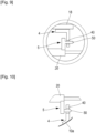
- FIG 10 an alternative embodiment of the embodiment illustrated in figure 4 where the complementary connection element 5 of the actuator 2 comprises the pin 50 and the complementary connection element 4 of the fixed structure 10, here the external structure 10a, for example the deflection edge 19a of the fixed structure 10, comprises the opening 40.
- the actuator 2 may be a simple linear actuator actuated electrically, hydraulically or pneumatically. Or that this actuator 2 may be attached to the fixed structure 10 between two longitudinal lines of attachment of the deflection means 15.
Landscapes
- Engineering & Computer Science (AREA)
- Chemical & Material Sciences (AREA)
- Combustion & Propulsion (AREA)
- Mechanical Engineering (AREA)
- General Engineering & Computer Science (AREA)
- Turbine Rotor Nozzle Sealing (AREA)
- Transmission Devices (AREA)
- Wind Motors (AREA)
Claims (15)
- Schubumkehrer (1) für eine Gondel eines Flugzeugs mit Strahltriebwerk, der Folgendes umfasst:- eine feste Struktur (10),- eine bewegliche Struktur (11),- ein Stellglied (2), das sich entlang einer Hauptachse (A1) erstreckt und über eine erste Verbindung (P1) mit der festen Struktur (10) und über eine zweite Verbindung (P2) mit der beweglichen Struktur (11) verbunden ist, um die bewegliche Struktur (11) zwischen einer Direktstrahlposition und einer Umkehrstrahlposition zu bewegen,dadurch gekennzeichnet, dass:das Stellglied (2) ferner durch eine dritte Verbindung (P3), die in Längsrichtung zwischen der ersten Verbindung (P1) und der zweiten Verbindung (P2) angeordnet ist, mit der festen Struktur (10) verbunden ist,die Achse (A3) der dritten Verbindung (P3) radial exzentrisch von der Hauptachse (A1) ist und die dritte Verbindung (P3) eine vorbestimmte Verschiebung des Stellglieds (2) in Bezug auf die feste Struktur (10) gestattet.
- Schubumkehrer (1) nach dem vorhergehenden Anspruch, dadurch gekennzeichnet, dass die dritte Verbindung (P3) komplementäre Verbindungselemente (4, 5) zwischen dem Stellglied (2) und der festen Struktur (10) umfasst.
- Schubumkehrer (1) nach dem vorhergehenden Anspruch, dadurch gekennzeichnet, dass die komplementären Verbindungselemente (4, 5) einen Stift (50) und eine Öffnung (40) umfassen, wobei der Stift (50) zumindest teilweise in der Öffnung (40) untergebracht ist.
- Schubumkehrer (1) nach dem vorhergehenden Anspruch, dadurch gekennzeichnet, dass zwischen der Öffnung (40) und dem Stift (50) ein radiales Spiel (7) ausgebildet ist.
- Schubumkehrer (1) nach einem der Ansprüche 3 oder 4, dadurch gekennzeichnet, dass die Öffnung (40) und der Stift (50) pressgepasst sind.
- Schubumkehrer (1) nach einem der Ansprüche 3 bis 5, dadurch gekennzeichnet, dass zwischen der Öffnung (40) und dem Stift (50) ein elastischer Dämpfer (8) positioniert ist.
- Schubumkehrer (1) nach einem der Ansprüche 3 bis 6, dadurch gekennzeichnet, dass der Stift (50) parallel zur Hauptachse (A1) des Stellglieds (2) ausgerichtet ist.
- Schubumkehrer (1) nach einem der Ansprüche 2 bis 7, dadurch gekennzeichnet, dass das komplementäre Verbindungselement (4) der festen Struktur (10) von einer Ablenkeinrichtung (15) oder einer Trägerstruktur der Ablenkeinrichtung getragen wird.
- Schubumkehrer (1) nach einem der Ansprüche 2 bis 7, dadurch gekennzeichnet, dass das komplementäre Verbindungselement (4) der festen Struktur (10) von einer externen Struktur (10a) der festen Struktur (10) getragen wird.
- Schubumkehrer (1) nach einem der Ansprüche 2 bis 9, dadurch gekennzeichnet, dass das Stellglied (2) einen Körper (20) und eine Stange (21) umfasst, wobei die Stange (21) von dem Körper (20) geführt wird, wobei das komplementäre Verbindungselement (5) des Stellglieds (2) von dem Körper (20) des Stellglieds (2) getragen wird.
- Schubumkehrer (1) nach einem der Ansprüche 2 bis 10, dadurch gekennzeichnet, dass die komplementären Verbindungselemente (4, 5) der festen Struktur (10) und des Stellglieds (2) jeweils eine ebene Oberfläche (42', 5') umfassen, die durch ein axiales Spiel (9) voneinander beabstandet sind.
- Schubumkehrer (1) nach dem vorhergehenden Anspruch, dadurch gekennzeichnet, dass die ebene Oberfläche (5') des komplementären Verbindungselements (5) des Stellglieds (2) durch eine Auskragung (5) des Körpers (20) des Stellglieds (2) ausgebildet ist.
- Schubumkehrer (1) nach Anspruch 11, dadurch gekennzeichnet, dass die ebene Oberfläche (5') des komplementären Verbindungselements (5) des Stellglieds (2) durch zwei Auskragungen (5) ausgebildet ist, die sich vom Körper (20) des Stellglieds (2) erstrecken, und die ebene Oberfläche (42') des komplementären Verbindungselements (4) der festen Struktur (10) durch zwei Vorsprünge (4) in Übereinstimmung mit den Auskragungen (5) ausgebildet ist.
- Schubumkehrer (1) nach einem der Ansprüche 11 bis 13, dadurch gekennzeichnet, dass die ebene Oberfläche (42') des komplementären Verbindungselements (4) der festen Struktur (10) durch eine radiale Wand (42) ausgebildet ist.
- Gondel für ein Flugzeug, umfassend einen Schubumkehrer (1) nach einem der vorhergehenden Ansprüche.
Applications Claiming Priority (2)
| Application Number | Priority Date | Filing Date | Title |
|---|---|---|---|
| FR1914901A FR3105304B1 (fr) | 2019-12-19 | 2019-12-19 | Inverseur de poussée avec système d’actionnement anti-flambage |
| PCT/FR2020/052468 WO2021123621A1 (fr) | 2019-12-19 | 2020-12-16 | Inverseur de poussée avec système d'actionnement anti-flambage |
Publications (2)
| Publication Number | Publication Date |
|---|---|
| EP4077903A1 EP4077903A1 (de) | 2022-10-26 |
| EP4077903B1 true EP4077903B1 (de) | 2024-10-02 |
Family
ID=69811282
Family Applications (1)
| Application Number | Title | Priority Date | Filing Date |
|---|---|---|---|
| EP20845594.9A Active EP4077903B1 (de) | 2019-12-19 | 2020-12-16 | Schubumkehrer mit knickschutzbetätigungssystem |
Country Status (5)
| Country | Link |
|---|---|
| US (1) | US11952963B2 (de) |
| EP (1) | EP4077903B1 (de) |
| CN (1) | CN114829760B (de) |
| FR (1) | FR3105304B1 (de) |
| WO (1) | WO2021123621A1 (de) |
Families Citing this family (1)
| Publication number | Priority date | Publication date | Assignee | Title |
|---|---|---|---|---|
| FR3126452B1 (fr) * | 2021-08-25 | 2024-11-01 | Safran Nacelles | Inverseur à grilles mobiles pour ensemble propulsif d’aéronef, comprenant un système pour limiter le flambage d’un actionneur de l’inverseur |
Citations (1)
| Publication number | Priority date | Publication date | Assignee | Title |
|---|---|---|---|---|
| US3532275A (en) * | 1967-11-09 | 1970-10-06 | Rohr Corp | Jet reverser drive system |
Family Cites Families (21)
| Publication number | Priority date | Publication date | Assignee | Title |
|---|---|---|---|---|
| US6311928B1 (en) * | 2000-01-05 | 2001-11-06 | Stage Iii Technologies, L.C. | Jet engine cascade thrust reverser for use with mixer/ejector noise suppressor |
| FR2907512B1 (fr) | 2006-10-23 | 2008-12-12 | Aircelle Sa | Inverseur de poussee a grilles pour moteur a reaction |
| FR2917788B1 (fr) * | 2007-06-19 | 2009-07-24 | Aircelle Sa | Actionneur double action a effet programme |
| GB0818701D0 (en) * | 2008-10-13 | 2008-11-19 | Goodrich Actuation Systems Ltd | Actuator |
| FR2946696B1 (fr) * | 2009-06-10 | 2012-04-20 | Aircelle Sa | Dispositif d'inversion de poussee |
| FR2978516B1 (fr) * | 2011-07-29 | 2013-08-02 | Aircelle Sa | Actionneur lineaire double action |
| FR2978800B1 (fr) | 2011-08-05 | 2014-05-23 | Aircelle Sa | Nacelle de turboreacteur a tuyere variable |
| FR2981989B1 (fr) * | 2011-10-31 | 2013-11-01 | Aircelle Sa | Inverseur de poussee a grilles mobiles et capot mobile monobloc |
| DE102012002885A1 (de) * | 2012-02-14 | 2013-08-14 | Rolls-Royce Deutschland Ltd & Co Kg | Fluggasturbinenschubumkehrvorrichtung |
| US10473057B2 (en) * | 2015-12-14 | 2019-11-12 | Rohr, Inc. | Thrust reverser system with translating elements |
| US10428764B2 (en) * | 2016-02-10 | 2019-10-01 | Rohr, Inc. | Deflection limiter for a cascade assembly of a thrust reverser |
| US10316793B2 (en) * | 2016-03-11 | 2019-06-11 | Rohr, Inc. | Thrust reverser track beam with integrated actuator fitting |
| US9976696B2 (en) * | 2016-06-21 | 2018-05-22 | Rohr, Inc. | Linear actuator with multi-degree of freedom mounting structure |
| US10662897B2 (en) * | 2017-01-18 | 2020-05-26 | Woodward, Inc. | Over-center thrust reverser primary lock |
| FR3075885B1 (fr) * | 2017-12-21 | 2020-01-10 | Safran Aircraft Engines | Turboreacteur equipe d'un actionneur a double effet, pouvant etre utilise pour commander une inversion de poussee |
| FR3078111B1 (fr) * | 2018-02-22 | 2020-01-17 | Airbus Sas | Turboreacteur comportant une nacelle equipee d'un systeme inverseur comportant des portes exterieures et interieures |
| FR3079213B1 (fr) * | 2018-03-23 | 2020-02-28 | Airbus Operations | Nacelle equipee d'un systeme inverseur comportant des portes et des systemes anti-vibration des portes en position stockee |
| US11346304B2 (en) * | 2018-09-06 | 2022-05-31 | Rohr, Inc. | Thrust reverser single degree of freedom actuator mechanism systems and methods |
| US11441514B2 (en) * | 2018-10-02 | 2022-09-13 | Woodward, Inc. | Tertiary lock |
| US11434848B2 (en) * | 2019-11-05 | 2022-09-06 | Rohr, Inc. | Drive system for translating structure |
| EP3943737B1 (de) * | 2020-04-07 | 2025-08-20 | Rohr, Inc. | Schubumkehrsystem mit versteckter tür für ein flugzeugantriebssystem |
-
2019
- 2019-12-19 FR FR1914901A patent/FR3105304B1/fr active Active
-
2020
- 2020-12-16 EP EP20845594.9A patent/EP4077903B1/de active Active
- 2020-12-16 CN CN202080088835.0A patent/CN114829760B/zh active Active
- 2020-12-16 WO PCT/FR2020/052468 patent/WO2021123621A1/fr not_active Ceased
-
2022
- 2022-06-17 US US17/843,219 patent/US11952963B2/en active Active
Patent Citations (1)
| Publication number | Priority date | Publication date | Assignee | Title |
|---|---|---|---|---|
| US3532275A (en) * | 1967-11-09 | 1970-10-06 | Rohr Corp | Jet reverser drive system |
Also Published As
| Publication number | Publication date |
|---|---|
| CN114829760A (zh) | 2022-07-29 |
| US20220316427A1 (en) | 2022-10-06 |
| FR3105304B1 (fr) | 2021-12-10 |
| FR3105304A1 (fr) | 2021-06-25 |
| EP4077903A1 (de) | 2022-10-26 |
| US11952963B2 (en) | 2024-04-09 |
| CN114829760B (zh) | 2025-01-28 |
| WO2021123621A1 (fr) | 2021-06-24 |
Similar Documents
| Publication | Publication Date | Title |
|---|---|---|
| EP2739841B1 (de) | Schubumkehrer mit beweglichen kaskaden und übersetzbar variabler düse | |
| EP2739840B1 (de) | Triebwerksgondel mit verstellbarer düse | |
| EP2742228A1 (de) | Schubumkehrvorrichtung | |
| EP4048883B1 (de) | Schubumkehrvorrichtung mit klappen, die durch einen mechanismus mit aeronautischen winkelhebeln gesteuert werden | |
| FR2966883A1 (fr) | Dispositif d'inversion de poussee sans bielle dans la veine | |
| FR2757215A1 (fr) | Inverseur de poussee de turboreacteur a portes comportant des aubes deflectrices associees a la structure fixe | |
| EP3740666B1 (de) | Hintere baugruppe einer triebwerksgondel eines luftfahrzeugs mit gleitender kaskadenschubumkehrvorrichtung | |
| WO2010012878A1 (fr) | Dispositif d'inversion de poussée | |
| FR2966882A1 (fr) | Inverseur de poussee pour turboreacteur d'aeronef a nombre d'actionneurs reduit | |
| FR2959532A1 (fr) | Nacelle de turboreacteur | |
| FR2962978A1 (fr) | Nacelle de turboreacteur | |
| WO2015193579A2 (fr) | Inverseur de poussée pour nacelle de turboréacteur d'aéronef | |
| FR3006716A1 (fr) | Inverseur de poussee a volet de blocage articule par embiellage trois points | |
| EP4077903B1 (de) | Schubumkehrer mit knickschutzbetätigungssystem | |
| EP3891374A1 (de) | Schubumkehrvorrichtung mit einer leichten schubumkehrklappe | |
| FR3002593A1 (fr) | Actionneur pour nacelle de turboreacteur d'aeronef | |
| WO2010012874A2 (fr) | Dispositif d'inversion de poussée | |
| WO2009112749A2 (fr) | Inverseur de poussée pour nacelle de turboréacteur à double flux | |
| WO2015145056A1 (fr) | Dispositif d'inversion de poussée sans grille pour nacelle de turboréacteur d'aéronef | |
| EP4323631B1 (de) | Schubumkehrvorrichtung mit beweglicher kaszade mit einer multifunktionalen festen struktur | |
| WO2009125157A2 (fr) | Nacelle de turboréacteur à double flux | |
| FR3137417A1 (fr) | Inverseur de poussee pour une nacelle d’un turboreacteur | |
| EP4337850A1 (de) | Flugzeugantriebsanordnung mit einem aktuator, der mit einem strukturarm wie etwa einer auslassleitschaufel verbunden ist |
Legal Events
| Date | Code | Title | Description |
|---|---|---|---|
| STAA | Information on the status of an ep patent application or granted ep patent |
Free format text: STATUS: UNKNOWN |
|
| STAA | Information on the status of an ep patent application or granted ep patent |
Free format text: STATUS: THE INTERNATIONAL PUBLICATION HAS BEEN MADE |
|
| PUAI | Public reference made under article 153(3) epc to a published international application that has entered the european phase |
Free format text: ORIGINAL CODE: 0009012 |
|
| STAA | Information on the status of an ep patent application or granted ep patent |
Free format text: STATUS: REQUEST FOR EXAMINATION WAS MADE |
|
| 17P | Request for examination filed |
Effective date: 20220708 |
|
| AK | Designated contracting states |
Kind code of ref document: A1 Designated state(s): AL AT BE BG CH CY CZ DE DK EE ES FI FR GB GR HR HU IE IS IT LI LT LU LV MC MK MT NL NO PL PT RO RS SE SI SK SM TR |
|
| DAV | Request for validation of the european patent (deleted) | ||
| DAX | Request for extension of the european patent (deleted) | ||
| GRAP | Despatch of communication of intention to grant a patent |
Free format text: ORIGINAL CODE: EPIDOSNIGR1 |
|
| STAA | Information on the status of an ep patent application or granted ep patent |
Free format text: STATUS: GRANT OF PATENT IS INTENDED |
|
| INTG | Intention to grant announced |
Effective date: 20240515 |
|
| GRAS | Grant fee paid |
Free format text: ORIGINAL CODE: EPIDOSNIGR3 |
|
| GRAA | (expected) grant |
Free format text: ORIGINAL CODE: 0009210 |
|
| STAA | Information on the status of an ep patent application or granted ep patent |
Free format text: STATUS: THE PATENT HAS BEEN GRANTED |
|
| AK | Designated contracting states |
Kind code of ref document: B1 Designated state(s): AL AT BE BG CH CY CZ DE DK EE ES FI FR GB GR HR HU IE IS IT LI LT LU LV MC MK MT NL NO PL PT RO RS SE SI SK SM TR |
|
| REG | Reference to a national code |
Ref country code: GB Ref legal event code: FG4D Free format text: NOT ENGLISH |
|
| REG | Reference to a national code |
Ref country code: CH Ref legal event code: EP |
|
| REG | Reference to a national code |
Ref country code: DE Ref legal event code: R096 Ref document number: 602020038799 Country of ref document: DE |
|
| REG | Reference to a national code |
Ref country code: IE Ref legal event code: FG4D Free format text: LANGUAGE OF EP DOCUMENT: FRENCH |
|
| REG | Reference to a national code |
Ref country code: LT Ref legal event code: MG9D |
|
| REG | Reference to a national code |
Ref country code: NL Ref legal event code: MP Effective date: 20241002 |
|
| REG | Reference to a national code |
Ref country code: AT Ref legal event code: MK05 Ref document number: 1728678 Country of ref document: AT Kind code of ref document: T Effective date: 20241002 |
|
| PG25 | Lapsed in a contracting state [announced via postgrant information from national office to epo] |
Ref country code: NL Free format text: LAPSE BECAUSE OF FAILURE TO SUBMIT A TRANSLATION OF THE DESCRIPTION OR TO PAY THE FEE WITHIN THE PRESCRIBED TIME-LIMIT Effective date: 20241002 |
|
| PG25 | Lapsed in a contracting state [announced via postgrant information from national office to epo] |
Ref country code: NL Free format text: LAPSE BECAUSE OF FAILURE TO SUBMIT A TRANSLATION OF THE DESCRIPTION OR TO PAY THE FEE WITHIN THE PRESCRIBED TIME-LIMIT Effective date: 20241002 |
|
| PG25 | Lapsed in a contracting state [announced via postgrant information from national office to epo] |
Ref country code: IS Free format text: LAPSE BECAUSE OF FAILURE TO SUBMIT A TRANSLATION OF THE DESCRIPTION OR TO PAY THE FEE WITHIN THE PRESCRIBED TIME-LIMIT Effective date: 20250202 Ref country code: HR Free format text: LAPSE BECAUSE OF FAILURE TO SUBMIT A TRANSLATION OF THE DESCRIPTION OR TO PAY THE FEE WITHIN THE PRESCRIBED TIME-LIMIT Effective date: 20241002 Ref country code: PT Free format text: LAPSE BECAUSE OF FAILURE TO SUBMIT A TRANSLATION OF THE DESCRIPTION OR TO PAY THE FEE WITHIN THE PRESCRIBED TIME-LIMIT Effective date: 20250203 |
|
| PG25 | Lapsed in a contracting state [announced via postgrant information from national office to epo] |
Ref country code: FI Free format text: LAPSE BECAUSE OF FAILURE TO SUBMIT A TRANSLATION OF THE DESCRIPTION OR TO PAY THE FEE WITHIN THE PRESCRIBED TIME-LIMIT Effective date: 20241002 |
|
| PG25 | Lapsed in a contracting state [announced via postgrant information from national office to epo] |
Ref country code: BG Free format text: LAPSE BECAUSE OF FAILURE TO SUBMIT A TRANSLATION OF THE DESCRIPTION OR TO PAY THE FEE WITHIN THE PRESCRIBED TIME-LIMIT Effective date: 20241002 |
|
| PG25 | Lapsed in a contracting state [announced via postgrant information from national office to epo] |
Ref country code: ES Free format text: LAPSE BECAUSE OF FAILURE TO SUBMIT A TRANSLATION OF THE DESCRIPTION OR TO PAY THE FEE WITHIN THE PRESCRIBED TIME-LIMIT Effective date: 20241002 |
|
| PG25 | Lapsed in a contracting state [announced via postgrant information from national office to epo] |
Ref country code: NO Free format text: LAPSE BECAUSE OF FAILURE TO SUBMIT A TRANSLATION OF THE DESCRIPTION OR TO PAY THE FEE WITHIN THE PRESCRIBED TIME-LIMIT Effective date: 20250102 |
|
| PG25 | Lapsed in a contracting state [announced via postgrant information from national office to epo] |
Ref country code: LV Free format text: LAPSE BECAUSE OF FAILURE TO SUBMIT A TRANSLATION OF THE DESCRIPTION OR TO PAY THE FEE WITHIN THE PRESCRIBED TIME-LIMIT Effective date: 20241002 Ref country code: AT Free format text: LAPSE BECAUSE OF FAILURE TO SUBMIT A TRANSLATION OF THE DESCRIPTION OR TO PAY THE FEE WITHIN THE PRESCRIBED TIME-LIMIT Effective date: 20241002 Ref country code: GR Free format text: LAPSE BECAUSE OF FAILURE TO SUBMIT A TRANSLATION OF THE DESCRIPTION OR TO PAY THE FEE WITHIN THE PRESCRIBED TIME-LIMIT Effective date: 20250103 |
|
| PG25 | Lapsed in a contracting state [announced via postgrant information from national office to epo] |
Ref country code: PL Free format text: LAPSE BECAUSE OF FAILURE TO SUBMIT A TRANSLATION OF THE DESCRIPTION OR TO PAY THE FEE WITHIN THE PRESCRIBED TIME-LIMIT Effective date: 20241002 Ref country code: CZ Free format text: LAPSE BECAUSE OF FAILURE TO SUBMIT A TRANSLATION OF THE DESCRIPTION OR TO PAY THE FEE WITHIN THE PRESCRIBED TIME-LIMIT Effective date: 20241002 |
|
| PG25 | Lapsed in a contracting state [announced via postgrant information from national office to epo] |
Ref country code: RS Free format text: LAPSE BECAUSE OF FAILURE TO SUBMIT A TRANSLATION OF THE DESCRIPTION OR TO PAY THE FEE WITHIN THE PRESCRIBED TIME-LIMIT Effective date: 20250102 |
|
| PG25 | Lapsed in a contracting state [announced via postgrant information from national office to epo] |
Ref country code: SM Free format text: LAPSE BECAUSE OF FAILURE TO SUBMIT A TRANSLATION OF THE DESCRIPTION OR TO PAY THE FEE WITHIN THE PRESCRIBED TIME-LIMIT Effective date: 20241002 |
|
| REG | Reference to a national code |
Ref country code: DE Ref legal event code: R097 Ref document number: 602020038799 Country of ref document: DE |
|
| PG25 | Lapsed in a contracting state [announced via postgrant information from national office to epo] |
Ref country code: MC Free format text: LAPSE BECAUSE OF FAILURE TO SUBMIT A TRANSLATION OF THE DESCRIPTION OR TO PAY THE FEE WITHIN THE PRESCRIBED TIME-LIMIT Effective date: 20241002 |
|
| PG25 | Lapsed in a contracting state [announced via postgrant information from national office to epo] |
Ref country code: DK Free format text: LAPSE BECAUSE OF FAILURE TO SUBMIT A TRANSLATION OF THE DESCRIPTION OR TO PAY THE FEE WITHIN THE PRESCRIBED TIME-LIMIT Effective date: 20241002 |
|
| PG25 | Lapsed in a contracting state [announced via postgrant information from national office to epo] |
Ref country code: EE Free format text: LAPSE BECAUSE OF FAILURE TO SUBMIT A TRANSLATION OF THE DESCRIPTION OR TO PAY THE FEE WITHIN THE PRESCRIBED TIME-LIMIT Effective date: 20241002 |
|
| PG25 | Lapsed in a contracting state [announced via postgrant information from national office to epo] |
Ref country code: RO Free format text: LAPSE BECAUSE OF FAILURE TO SUBMIT A TRANSLATION OF THE DESCRIPTION OR TO PAY THE FEE WITHIN THE PRESCRIBED TIME-LIMIT Effective date: 20241002 |
|
| PG25 | Lapsed in a contracting state [announced via postgrant information from national office to epo] |
Ref country code: SK Free format text: LAPSE BECAUSE OF FAILURE TO SUBMIT A TRANSLATION OF THE DESCRIPTION OR TO PAY THE FEE WITHIN THE PRESCRIBED TIME-LIMIT Effective date: 20241002 |
|
| PG25 | Lapsed in a contracting state [announced via postgrant information from national office to epo] |
Ref country code: IT Free format text: LAPSE BECAUSE OF FAILURE TO SUBMIT A TRANSLATION OF THE DESCRIPTION OR TO PAY THE FEE WITHIN THE PRESCRIBED TIME-LIMIT Effective date: 20241002 |
|
| REG | Reference to a national code |
Ref country code: CH Ref legal event code: PL |
|
| PLBE | No opposition filed within time limit |
Free format text: ORIGINAL CODE: 0009261 |
|
| STAA | Information on the status of an ep patent application or granted ep patent |
Free format text: STATUS: NO OPPOSITION FILED WITHIN TIME LIMIT |
|
| PG25 | Lapsed in a contracting state [announced via postgrant information from national office to epo] |
Ref country code: LU Free format text: LAPSE BECAUSE OF NON-PAYMENT OF DUE FEES Effective date: 20241216 |
|
| PG25 | Lapsed in a contracting state [announced via postgrant information from national office to epo] |
Ref country code: SE Free format text: LAPSE BECAUSE OF FAILURE TO SUBMIT A TRANSLATION OF THE DESCRIPTION OR TO PAY THE FEE WITHIN THE PRESCRIBED TIME-LIMIT Effective date: 20241002 |
|
| 26N | No opposition filed |
Effective date: 20250703 |
|
| REG | Reference to a national code |
Ref country code: BE Ref legal event code: MM Effective date: 20241231 |
|
| PG25 | Lapsed in a contracting state [announced via postgrant information from national office to epo] |
Ref country code: BE Free format text: LAPSE BECAUSE OF NON-PAYMENT OF DUE FEES Effective date: 20241231 |
|
| PG25 | Lapsed in a contracting state [announced via postgrant information from national office to epo] |
Ref country code: CH Free format text: LAPSE BECAUSE OF NON-PAYMENT OF DUE FEES Effective date: 20241231 |
|
| PG25 | Lapsed in a contracting state [announced via postgrant information from national office to epo] |
Ref country code: IE Free format text: LAPSE BECAUSE OF NON-PAYMENT OF DUE FEES Effective date: 20241216 |
|
| PGFP | Annual fee paid to national office [announced via postgrant information from national office to epo] |
Ref country code: GB Payment date: 20251229 Year of fee payment: 6 |
|
| PGFP | Annual fee paid to national office [announced via postgrant information from national office to epo] |
Ref country code: FR Payment date: 20251222 Year of fee payment: 6 |
|
| PGFP | Annual fee paid to national office [announced via postgrant information from national office to epo] |
Ref country code: DE Payment date: 20251222 Year of fee payment: 6 |