EP4076928B1 - Formage de conteneurs par pliage de plaques cartonnees - Google Patents
Formage de conteneurs par pliage de plaques cartonnees Download PDFInfo
- Publication number
- EP4076928B1 EP4076928B1 EP20824940.9A EP20824940A EP4076928B1 EP 4076928 B1 EP4076928 B1 EP 4076928B1 EP 20824940 A EP20824940 A EP 20824940A EP 4076928 B1 EP4076928 B1 EP 4076928B1
- Authority
- EP
- European Patent Office
- Prior art keywords
- punch
- folding
- plate
- die
- sheet
- Prior art date
- Legal status (The legal status is an assumption and is not a legal conclusion. Google has not performed a legal analysis and makes no representation as to the accuracy of the status listed.)
- Active
Links
Images


Classifications
-
- B—PERFORMING OPERATIONS; TRANSPORTING
- B31—MAKING ARTICLES OF PAPER, CARDBOARD OR MATERIAL WORKED IN A MANNER ANALOGOUS TO PAPER; WORKING PAPER, CARDBOARD OR MATERIAL WORKED IN A MANNER ANALOGOUS TO PAPER
- B31B—MAKING CONTAINERS OF PAPER, CARDBOARD OR MATERIAL WORKED IN A MANNER ANALOGOUS TO PAPER
- B31B50/00—Making rigid or semi-rigid containers, e.g. boxes or cartons
- B31B50/26—Folding sheets, blanks or webs
- B31B50/44—Folding sheets, blanks or webs by plungers moving through folding dies
-
- B—PERFORMING OPERATIONS; TRANSPORTING
- B31—MAKING ARTICLES OF PAPER, CARDBOARD OR MATERIAL WORKED IN A MANNER ANALOGOUS TO PAPER; WORKING PAPER, CARDBOARD OR MATERIAL WORKED IN A MANNER ANALOGOUS TO PAPER
- B31B—MAKING CONTAINERS OF PAPER, CARDBOARD OR MATERIAL WORKED IN A MANNER ANALOGOUS TO PAPER
- B31B50/00—Making rigid or semi-rigid containers, e.g. boxes or cartons
- B31B50/02—Feeding or positioning sheets, blanks or webs
- B31B50/04—Feeding sheets or blanks
- B31B50/044—Feeding sheets or blanks involving aligning
-
- B—PERFORMING OPERATIONS; TRANSPORTING
- B31—MAKING ARTICLES OF PAPER, CARDBOARD OR MATERIAL WORKED IN A MANNER ANALOGOUS TO PAPER; WORKING PAPER, CARDBOARD OR MATERIAL WORKED IN A MANNER ANALOGOUS TO PAPER
- B31B—MAKING CONTAINERS OF PAPER, CARDBOARD OR MATERIAL WORKED IN A MANNER ANALOGOUS TO PAPER
- B31B2100/00—Rigid or semi-rigid containers made by folding single-piece sheets, blanks or webs
- B31B2100/002—Rigid or semi-rigid containers made by folding single-piece sheets, blanks or webs characterised by the shape of the blank from which they are formed
- B31B2100/0026—Rigid or semi-rigid containers made by folding single-piece sheets, blanks or webs characterised by the shape of the blank from which they are formed having two opposite first side walls attached to the bottom and the other side walls being attached to the first side walls
-
- B—PERFORMING OPERATIONS; TRANSPORTING
- B31—MAKING ARTICLES OF PAPER, CARDBOARD OR MATERIAL WORKED IN A MANNER ANALOGOUS TO PAPER; WORKING PAPER, CARDBOARD OR MATERIAL WORKED IN A MANNER ANALOGOUS TO PAPER
- B31B—MAKING CONTAINERS OF PAPER, CARDBOARD OR MATERIAL WORKED IN A MANNER ANALOGOUS TO PAPER
- B31B2110/00—Shape of rigid or semi-rigid containers
- B31B2110/30—Shape of rigid or semi-rigid containers having a polygonal cross section
- B31B2110/35—Shape of rigid or semi-rigid containers having a polygonal cross section rectangular, e.g. square
-
- B—PERFORMING OPERATIONS; TRANSPORTING
- B31—MAKING ARTICLES OF PAPER, CARDBOARD OR MATERIAL WORKED IN A MANNER ANALOGOUS TO PAPER; WORKING PAPER, CARDBOARD OR MATERIAL WORKED IN A MANNER ANALOGOUS TO PAPER
- B31B—MAKING CONTAINERS OF PAPER, CARDBOARD OR MATERIAL WORKED IN A MANNER ANALOGOUS TO PAPER
- B31B2120/00—Construction of rigid or semi-rigid containers
- B31B2120/10—Construction of rigid or semi-rigid containers provided with covers, e.g. lids
- B31B2120/102—Construction of rigid or semi-rigid containers provided with covers, e.g. lids with a hinged cover
-
- B—PERFORMING OPERATIONS; TRANSPORTING
- B31—MAKING ARTICLES OF PAPER, CARDBOARD OR MATERIAL WORKED IN A MANNER ANALOGOUS TO PAPER; WORKING PAPER, CARDBOARD OR MATERIAL WORKED IN A MANNER ANALOGOUS TO PAPER
- B31B—MAKING CONTAINERS OF PAPER, CARDBOARD OR MATERIAL WORKED IN A MANNER ANALOGOUS TO PAPER
- B31B50/00—Making rigid or semi-rigid containers, e.g. boxes or cartons
- B31B50/02—Feeding or positioning sheets, blanks or webs
- B31B50/022—Holders for feeding or positioning blanks or webs
-
- B—PERFORMING OPERATIONS; TRANSPORTING
- B31—MAKING ARTICLES OF PAPER, CARDBOARD OR MATERIAL WORKED IN A MANNER ANALOGOUS TO PAPER; WORKING PAPER, CARDBOARD OR MATERIAL WORKED IN A MANNER ANALOGOUS TO PAPER
- B31B—MAKING CONTAINERS OF PAPER, CARDBOARD OR MATERIAL WORKED IN A MANNER ANALOGOUS TO PAPER
- B31B50/00—Making rigid or semi-rigid containers, e.g. boxes or cartons
- B31B50/02—Feeding or positioning sheets, blanks or webs
- B31B50/04—Feeding sheets or blanks
- B31B50/046—Feeding sheets or blanks involving changing orientation or changing direction of transport
-
- B—PERFORMING OPERATIONS; TRANSPORTING
- B31—MAKING ARTICLES OF PAPER, CARDBOARD OR MATERIAL WORKED IN A MANNER ANALOGOUS TO PAPER; WORKING PAPER, CARDBOARD OR MATERIAL WORKED IN A MANNER ANALOGOUS TO PAPER
- B31B—MAKING CONTAINERS OF PAPER, CARDBOARD OR MATERIAL WORKED IN A MANNER ANALOGOUS TO PAPER
- B31B50/00—Making rigid or semi-rigid containers, e.g. boxes or cartons
- B31B50/02—Feeding or positioning sheets, blanks or webs
- B31B50/04—Feeding sheets or blanks
- B31B50/06—Feeding sheets or blanks from stacks
- B31B50/066—Feeding sheets or blanks from stacks from above a magazine
-
- B—PERFORMING OPERATIONS; TRANSPORTING
- B31—MAKING ARTICLES OF PAPER, CARDBOARD OR MATERIAL WORKED IN A MANNER ANALOGOUS TO PAPER; WORKING PAPER, CARDBOARD OR MATERIAL WORKED IN A MANNER ANALOGOUS TO PAPER
- B31B—MAKING CONTAINERS OF PAPER, CARDBOARD OR MATERIAL WORKED IN A MANNER ANALOGOUS TO PAPER
- B31B50/00—Making rigid or semi-rigid containers, e.g. boxes or cartons
- B31B50/02—Feeding or positioning sheets, blanks or webs
- B31B50/04—Feeding sheets or blanks
- B31B50/07—Feeding sheets or blanks by air pressure or suction
-
- B—PERFORMING OPERATIONS; TRANSPORTING
- B65—CONVEYING; PACKING; STORING; HANDLING THIN OR FILAMENTARY MATERIAL
- B65B—MACHINES, APPARATUS OR DEVICES FOR, OR METHODS OF, PACKAGING ARTICLES OR MATERIALS; UNPACKING
- B65B43/00—Forming, feeding, opening or setting-up containers or receptacles in association with packaging
- B65B43/12—Feeding flexible bags or carton blanks in flat or collapsed state; Feeding flat bags connected to form a series or chain
- B65B43/14—Feeding individual bags or carton blanks from piles or magazines
- B65B43/16—Feeding individual bags or carton blanks from piles or magazines by grippers
- B65B43/18—Feeding individual bags or carton blanks from piles or magazines by grippers by suction-operated grippers
- B65B43/185—Feeding individual bags or carton blanks from piles or magazines by grippers by suction-operated grippers specially adapted for carton blanks
-
- B—PERFORMING OPERATIONS; TRANSPORTING
- B65—CONVEYING; PACKING; STORING; HANDLING THIN OR FILAMENTARY MATERIAL
- B65B—MACHINES, APPARATUS OR DEVICES FOR, OR METHODS OF, PACKAGING ARTICLES OR MATERIALS; UNPACKING
- B65B47/00—Apparatus or devices for forming pockets or receptacles in or from sheets, blanks, or webs, comprising essentially a die into which the material is pressed or a folding die through which the material is moved
- B65B47/04—Apparatus or devices for forming pockets or receptacles in or from sheets, blanks, or webs, comprising essentially a die into which the material is pressed or a folding die through which the material is moved by application of mechanical pressure
- B65B47/06—Apparatus or devices for forming pockets or receptacles in or from sheets, blanks, or webs, comprising essentially a die into which the material is pressed or a folding die through which the material is moved by application of mechanical pressure using folding dies
Definitions
- the present invention enters the field of forming by folding cardboard plates with a view to forming containers, for packaging one or more products.
- the term “product” encompasses an individual object.
- a product is a container, such as a bottle or flask, or a can, or even a cardboard brick.
- Such products can also be grouped, positioned within a carton (or “cluster”) and/or packaged in film.
- a product can be made of any type of material, in particular plastic, metal or even glass.
- a product can be rigid or semi-rigid.
- This container is intended to contain, in a non-exhaustive manner, a fluid, a liquid, powders or granules, in particular of the food or cosmetic type, or dedicated to maintenance or personal hygiene.
- a product can have any type of shape, symmetrical or not, regular or irregular.
- Such products are obtained along an industrial production line, undergoing several successive treatments passing through dedicated stations, such as for example the blowing of plastic bottles or vials, filling and capping, labeling, or even sterilization or pasteurization.
- dedicated stations such as for example the blowing of plastic bottles or vials, filling and capping, labeling, or even sterilization or pasteurization.
- the finished products are grouped and packaged in batches, particularly inside a container.
- Such a container can be in the form of a cardboard box or “cardboard”, dedicated to the packaging of said products.
- a carton has a rectangular parallelepiped shape, with an interior volume capable of receiving a group of products, in a staggered pattern but preferably arranged in a matrix in columns and rows, in a single layer or several layers of superimposed products. Once filled, a carton can be closed at the top or opened, forming a tray also called a “cartonette”.
- FIG 1 schematically representing an elevational view of an example of a cardboard plate 100, presented flat, it comprises several walls, including a bottom 101, intended to receive the products on the upper face, once the container 110 has been formed. At the levels of two of its opposite edges, the bottom 101 comprises two side walls 102.
- the cardboard plate 100 may include a cover 103, along an edge of one of the side walls 102, located opposite the edge connecting it with said bottom 101. This cover may also include a tab 104, which will be glued and folded against the exterior of a side wall 102, at the end of folding when closing the container 110 thus formed once the products have been introduced inside.
- the cardboard plate 100 comprises flaps, at least four in number on each side: on the one hand, vertical flaps 105 connected to each of the side walls 102 and, on the other hand , horizontal flaps 106 connected to the bottom 101 and to the cover 103.
- the different walls of the plate 100 are connected by folding lines, extending along the joining edges between them. Said folding lines are previously produced when cutting said plate 100 and facilitate the folding operations of each wall relative to another.
- the cardboard plate 100 is folded through several successive operations. These folding operations can be carried out using dedicated stations and in several different ways.
- the invention specifically relates to the folding of cardboard plates known as “die-bottom folding”.
- Die-bottom bending is carried out by cold deformation of a material within a press, provided with a fixed die in alignment with which a movable punch moves.
- FIG. 1 schematically representing perspective views of several stages during die-bottom folding of a cardboard plate 100, the latter is positioned between a die 200 and a punch 201.
- the bottom 101 is positioned opposite the matrix 200 of complementary shape, namely rectangular parallelepiped, with the folding lines aligned with the interior edges of said matrix 200.
- the punch 201 is positioned opposite upper of said bottom 101 and internally in relation to the future container 110 to be formed.
- the punch 201 is then moved downwards relative to the die 200, in particular vertically, to apply a thrust against the bottom 101 and thus force the side walls 102 against the inside of the faces of the die 200, with a view to folding towards the inside of the future container 110 said side walls 102 and towards the inside the vertical flaps 105 and horizontal 106, until they are positioned orthogonal to said background 101.
- the descent of the punch 201 first causes the start of the folding of the four vertical flaps 105, by pressing on the exterior face against dedicated studs specifically shaped and equipping said matrix 200. Then, as visible on the figure 4 , the two horizontal flaps 106 connected to the bottom 101, begin to be folded against other dedicated pads, to cover the vertical flaps 105 from the outside. Finally, as visible on the figure 4 , the end of travel of the punch 201 finishes folding the side walls 102, as well as the vertical flaps 105 and the horizontal flaps 106 linked to the bottom.
- the container 110 is formed and opened: the plate 100 then has an internal volume, open in the upper part.
- the punch 201 is removed and the container 110 is extracted from the matrix 200, with a view to introducing products into its interior volume, during a packaging operation, in particular boxing.
- the cover 103 is folded to close the container 110, possibly with a folding of the tab 104, to obtain the final container 110 surrounding and protecting the products it contains.
- a constraint of this type of die bottom bending is the required alignment of the fold lines with the die and punch, particularly in each corner. Furthermore, the precision of such alignment is of the order of a few millimeters (mm). Otherwise, during folding, an offset risks causing detrimental deformation of the container, or even tearing of the cardboard material at the time of this operation, in particular when lowering the punch.
- an optimal shape of the container rectangular parallelepiped, respecting the orthogonality of its walls, is important and must be optimal, on the one hand, for the aesthetic appearance and the good packaging of the products, but above all on the other hand , when several boxes must be stacked, particularly on pallets. A deformation of a single box is likely to unbalance a stack of boxes, making their handling precarious and dangerous for operators.
- the forming of containers by folding cardboard plates is carried out through a forming device.
- Such a forming device is already known from the documents FROM 10 2012 008817 A1 Or US 2010/263333 A1 and includes a folding station, supplied with cardboard plates which are formed there, as previously described.
- Such cardboard plates are arranged within a store, in the form of a stack of several plates superimposed horizontally or vertically.
- the plates are extracted one after the other during a handling step to transport them from said store to said folding station.
- This step may consist of extracting the plates one by one and transporting them along guided angles.
- the angles are fixed on a frame and shaped complementary to the cardboard plates and the containers to be formed. This installation therefore does not allow it to be adapted to different formats of cardboard plates, or requires significant intervention time.
- the handling of plates can be carried out via a dedicated station, mounted mobile along several axes of movement, via a multi-axis chassis or a multi-axis robotic arm.
- a handling station is provided with a gripping head for the plates unit.
- This gripping of each plate can be carried out by different gripping means, in particular by depression using suction cups.
- Each suction cup comes into contact with the face of a plate and performs suction ensuring said plate is held in place with a view to its extraction from said magazine and its movement towards the forming station. Suction grip is maintained during the bending operation, in order to maintain the plate in relation to the die and the punch. From then on, the gripping of the suction cups is carried out at the level of the upper face of the bottom, which will remain flat during the movement of the plate within the matrix under the action of the movement of the punch.
- the suction is stopped, in order to release said container.
- the punch is raised and the container is evacuated, for example from below the matrix, in particular via a conveyor which will transport each container to a downstream product packing station, before closing the container.
- the punch is attached to the handling station, at the level of the gripping head, integrally with the suction cups.
- the suction cups are found flush with the underside of said punch, to cooperate with the bottom during gripping. Therefore, the problem of aligning the corners of the cardboard plate with the die and the punch is considerably complicated.
- the punch must be aligned with the corners of the plate to be gripped, but the plates are generally not perfectly aligned in superposition in said magazine.
- the stored plates can have a lateral, but also angular, offset relative to each other. It is therefore necessary to correct this possible discrepancy.
- a known solution lies in detecting an offset, at the time of gripping in the magazine, of the exact position of the plate to be gripped, to correct the position of the gripping head, in particular to place the punch in alignment with the bottom corners.
- the invention aims to overcome the disadvantages of the state of the art by proposing a device for forming containers by folding cardboard plates, making it possible to correct a possible offset between the punch and a plate, once seized and at the moment of the bending operation at the bottom of the die.
- the invention provides, at the level of the gripping head, to make the suction cups free to move relative to the punch, in order to allow lateral and/or angular adjustment of the plate under the action of the punch during its descent into the matrix.
- the movement of the suction cups relative to the punch gives mobility to the gripping plane according to at least two degrees of freedom parallel or substantially parallel to the bottom of the gripped plate.
- the freedom of movement of the means of seizure allows a natural replacement of the background in alignment with the matrix, under the effect of the force applied by the cooperation between said matrix and said punch.
- the mobility of the gripping means which can for example be represented by at least one suction cup, makes it possible to make the folding lines of the bottom of the plate coincide with the matrix, by reducing the stresses applied to the cardboard material, to promote more repositioning. natural in alignment with said fold lines.
- Such a forming device is characterized in that said gripping means is mounted movable relative to said punch and free to move in at least one plane parallel to said bearing surface of said punch.
- said gripping means can be mounted movable in at least two degrees of freedom of movement parallel or substantially parallel to said support surface.
- the gripping means can be integrated into said partially hollow punch.
- Said gripping means can be mounted at the end of a rod mounted in a ball joint relative to the gripping head.
- Said forming device may comprise means for locking said gripping means relative to said punch.
- Said gripping means may comprise at least one suction cup acting by suction at said plate.
- the gripping means may comprise several free suction cups moving in said plane.
- Such a forming process is characterized in that it consists, at the time of folding, of adjusting the position of said bottom relative to said punch, leaving said plate free to move relative to said punch.
- the present invention relates to the making of containers 110.
- Such a container 110 can be in the form of a cardboard box or “cardboard”, dedicated to the packaging of products.
- a carton has a rectangular parallelepiped shape, with an interior volume capable of receiving a group of products, in a staggered pattern but preferably arranged in a matrix in columns and rows, in a single layer or several layers of superimposed products.
- a carton can be closed at the top or opened, forming a tray also called a “cartonette”.
- a product encompasses an individual object.
- a product is a container, such as a bottle or flask, or a can, or even a cardboard brick.
- a product can be made of any type of material, in particular plastic, metal or even glass.
- a product can be rigid or semi-rigid.
- This container is intended to contain, in a non-exhaustive manner, a fluid, a liquid, powders or granules, in particular of the food or cosmetic type, or dedicated to maintenance or personal hygiene.
- a product can have any type of shape, symmetrical or not, regular or irregular.
- Such products are obtained along an industrial production line, undergoing several successive treatments passing through dedicated stations, such as for example the blowing of plastic bottles or vials, filling and capping, labeling, or even sterilization or pasteurization.
- the finished products are grouped and packaged in batches, in particular inside containers 110.
- the invention aims to form containers 110 by folding cardboard plates 100. These cardboard plates are previously pre-cut and preformed, also called “cuts”.
- the term “plate” refers to a cardboard plate.
- a plate 100 comprises several walls, including a wall which will constitute a bottom 101, intended to receive the products on the upper face, once the container 110 has been formed.
- the bottom 101 comprises two side walls 102.
- the plate 100 may include a cover 103, along an edge of one of the side walls 102, located opposite the edge connecting it with said bottom 101.
- This cover can also include a tab 104, which will be glued and folded against the outside of a side wall 102, at the end of folding when closing the container 110 thus formed.
- the plate 100 comprises flaps, at least four in number on each side: on the one hand, vertical flaps 105 connected to each of the side walls 102 and, on the other hand, horizontal flaps 106 connected to the bottom 101 and to the cover 103.
- the different walls of the plate 100 are connected by folding lines, extending along the joining edges between them. Said folding lines are previously produced when cutting said plate 100 and facilitate the folding operations of each wall relative to another.
- the plate 100 is folded through several successive operations.
- a first folding operation makes it possible to form the container 110 by folding the side walls 102, as well as the vertical flaps 105, then the horizontal flaps 106 located on either side of said bottom 101. This first operation is carried out by folding at the bottom of the die. Container 110 is therefore formed once passed through the matrix 200.
- the invention relates to a device 1 for forming containers 110 by folding cardboard plates 100.
- Such a forming device 1 is located along the production line, between a store 2 supplied with plates 100 and a downstream station, such as for example a product packaging station inside the container 110. Once loaded with products, container 110 will be closed by a dedicated station.
- store 2 is supplied with plates 100, in particular from bundles.
- the plates 100 are placed in a reception area, superimposed horizontally or vertically, or even inclined, from where they can be extracted one by one.
- the forming device 1 comprises a station 3 for handling said plates 100 from the magazine 2.
- This handling station 3 ensures the transport of the plates 100 by grabbing them one by one, or even several at a time, to bring them to a station dedicated to folding.
- the forming device 1 comprises at least one station 4 for folding plates 100.
- the same station 4 can allow the folding of a single or several plates 100 at a time.
- said folding station is provided with at least one die 200.
- a die 200 comprises an upper face for receiving a plate 100, on which the lower face of the plate 100 can rest.
- This matrix 200 comprises a hollow central shape, dimensioned complementary to the bottom 101 of the plate 100, to the clearance close to the thickness of the side walls 102 and the flaps 105,106 once folded.
- the matrix 200 comprises studs, projecting relative to the upper face of said matrix 200, and shaped to allow the successive folding of the vertical flaps 105, then the side walls 102 and horizontal flaps 106 located below and connected to the bottom 101.
- the studs can be provided rounded, in order to cause the walls to fold progressively and gently.
- This folding operation is carried out under the action of a punch 201.
- Such a punch 201 is shaped complementary to the hollow of the die 200, to allow it to slide internally, with the aforementioned clearance.
- the punch 201 applies a force against the bottom 101 of the plate 100, said bottom 101 being sandwiched between said punch 201 and said die 200, so as to induce the folding of the different walls.
- the punch 201 applies a force against the die 200, which will constrain the plate 100 and bend it.
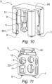
- the punch 201 comprises a support surface intended to cooperate at least at the edge of the bottom 101, for example in its corners as visible on the Figure 10 or on its entire interior perimeter as visible on the Figure 11 .
- This support surface may also include contact zones with other parts of the bottom 101, in particular located towards the center of said bottom 101, in order to distribute the applied force and avoid any deformation.
- the bearing surface of the punch 101 may include several zones coming into contact with the upper face of the bottom 101, against all or part of its surface.
- the punch 201 is extracted from the die 200, making it possible to evacuate this container 110, in particular from below the die 200 as visible on the Figure 7 , in particular towards a conveyor 5 which then takes the containers 110 towards a boxing station (not shown).
- the punch 201 can also be moved to eject the container 110 to another location, such as for example on said conveyor 5.
- the handling station 3 comprises a frame 30 and at least one gripping head 6 mounted movable relative to said frame 30 between said store 2 and the die 200 of said folding station 4.
- Such a chassis 30 is provided with multiple axes, making it possible to move the gripping head 6 in space, according to several degrees of movement.
- the chassis 30 includes a motorization of its own, authorizing the movements necessary to pick up the plates 100 from the magazine 2 by means of the gripping head 6, move said head 6 to the folding station 4, place the plates 100 there and return to the magazine 2 to pick up another plate 100. From then on, so non-exhaustive, the chassis 30 can allow movement according to horizontal translations, longitudinally and transversely, as well as vertical upward and downward movement, as in particular shown schematically on the figures 6 and 7 .
- the downward vertical movement given to the gripping head 6 is used during the folding step.
- said gripping head 6 integrates at least one punch 201. The latter is therefore transported during movements of the gripping head 6 between the folding station 4 and the magazine 2, and vice versa.
- the chassis 30 comprises several guides 31.
- the gripping head 6 is then secured to a guide 31 or mounted on a movable carriage along one of the guides 31, while the other guides can slide relative to each other.
- the chassis 30 comprises a multi-axis robotic arm, at the distal end of which the gripping head 6 is mounted as a tool.
- a robotic arm can also be mounted on guides 31. This arm notably allows better precision when gripping the plates 100 at the level of the magazine 2.
- the gripping head 6 can comprise a structure 60 cooperating in fixing with the chassis 30 and receiving various on-board components, such as the punch 201 which can be fixed on this structure 60.
- said gripping head 6 is equipped with means 7 for gripping and holding said plate 100.
- Such gripping means 7 ensures gripping of a plate 100, in particular at one of its faces, or even a side edge, then maintains it during its transport to the folding station 4, preferably by preventing it from moving in particular during the acceleration and deceleration phases.
- This gripping means 7 can be located at any location on the gripping head 6.
- the gripping means 7 can be mounted on the structure 60 of said gripping head 6.
- the gripping means 7 is integrated into said punch 201, attached to the latter, in particular via the structure 60 of the gripping head 6.
- the gripping means 7 is positioned at the distal end of the punch 201, flush with its bearing surface. Therefore, said bearing surface of the punch 201 is completed by the contact surface of the gripping means 7 against the place 100.
- the bearing surface corresponds to the contact surface between the means 7 of seizure and plate 100.
- the punch 201 can be provided at least partially hollow, delimiting an internal space capable of receiving said gripping means 7 and its fixing with said punch 201 or the structure 60 of the gripping head 6.
- the gripping means 7 can be of any type, for example in the form of needles sufficiently perforating the wall of a plate 100 in order to ensure its grip and retention.
- the input means 7 can also be an electrostatic type system.
- said gripping means 7 comprises at least one suction cup 8, preferably several suction cups 8, acting by suction at said plate 100.
- said suction cup 8 can be arranged so that its suction takes place flush with the bearing surface of said punch 201. Therefore, the bearing surface of the punch 201 is at least partially formed by the surface of suction of said suction cup 8.
- suction cups 8 can be distributed to apply depressions at several locations on the plate 100, in a plane alignment.
- this plane alignment is parallel or substantially parallel to the bearing surface of the punch 200.
- the forming device 1 makes it possible to move the gripping head 6 to the magazine 2, to grip a plate there under the action of the gripping means 7, then to transport it to the folding station 4, to position it on the die 200, to lower the punch 201 and fold the side walls of the plate 100, in order to form the container 110.
- the handling station 3 can provide for detecting the position of each plate 100 in the magazine 2, in order to align the punch 201 with the bottom 101 of the plate 100 to be gripped. This alignment makes it possible to compensate for any lateral or angular shift relative to an optimal position.
- the travel of the handling station 3 is determined in order, upon returning from store 2, to perfectly align the punch 201 with the die 200.
- the invention provides for improving the positioning of the gripped plate 100, when it is positioned with the punch 201 in alignment with the die 200.
- the invention provides for adjusting the position of the bottom 101, to that at least one of its corners is perfectly positioned relative to the die 200, at the time of the descent of the punch 201 into the die 200.
- said gripping means 7 is mounted movable relative to said punch 201.
- the plate 100 is always gripped and held, but the gripping means 7 can move, essentially parallel to the punch 201 and its surface of 'support. The movement of the gripping means 7 then makes it possible to move the plate 100 relative to the punch 201, without moving the latter relative to the frame 30.
- the gripping means 7 is free to move in at least one plane parallel to said bearing surface of said punch 201. In other words, no motorization ensures the movement of the gripping means 7, it is the construction of the gripping means 7 on the gripping head which gives it freedom of movement within a given perimeter.
- the gripping means 7 when the gripping means 7 is integrated into the punch 201, the gripping means 7 is in principle movable in at least the plane corresponding substantially to the plane of the support surface.
- said gripping means 7 is mounted movable in at least two degrees of freedom of movement parallel or substantially parallel to said support surface.
- FIG 8 schematically shows an example of repositioning a corner of the plate 100, carried out according to two orthogonal lateral translations. Only one translation is possible, this can be a result of these orthogonal translations: the corner then moving at an angle.
- freedom of movement can be limited to a few millimeters, of the order of plus or minus five millimeters (+/- 5mm).
- the free movement of the gripping means 7 takes place at a reduced distance, of the order of 2% to 5% relative to the dimensions of the bottom 101, in particular relative to its length or its width.
- said gripping means 7 may comprise an articulated assembly on the gripping head 6, in particular with respect to the structure 60 of said head 6 of grip.
- a joint can be of any type, in particular in the form of a double sliding connection.
- the articulation includes two sliding possibilities, preferably orthogonal to each other, of the gripping means 7.
- said gripping means 7 is articulated according to a ball joint, in particular via a cradle or joints.
- This ball joint can be mounted on the gripping head 6, in particular on its structure 60 and/or on said punch 201.
- the invention can provide for compensating it, in order to obtain a plane or substantially plane mobility of plate 100.
- the joint is offset, in particular at one end of the head 6 gripping, (for example in the upper part), while the gripping means 7 is located at the opposite end (in the lower part). This offset makes it possible to increase the radius of curvature of the movement of the ball joint.
- said gripping means 7 is mounted at the end of a rod 9 mounted in ball joint connection relative to the gripping head 6.
- the gripping means 7 is fixed to the lower end of a rod 9, the upper opposite end of which is ball-jointed on the gripping head 6.
- the gripping means 7 comprises several suction cups 8, they can be mounted independently, each being mobile and free to move in a distinct manner relative to the other suction cups 8.
- the gripping means 7 comprises several suction cups 8
- they can be mounted independently, each being mobile and free to move in a distinct manner relative to the other suction cups 8.
- the suction cups 8 when they are engaged by suction of the plate 100, in particular each suction cup 8 applying suction against an area of the bottom 101, then the latter plays the role of a junction surface, making the suction cups 8 integral with each other in their free movement.
- the suction cups 8 are integral with each other and jointly free to move in said plane.
- the suction cups 8 can be connected together, in particular by a mechanical part, such as a plate or rods.
- the invention provides for limiting the freedom of movement of the gripping means 7 outside the moment of folding, in particular to avoid any movement of the plate 100 gripped during movements of the gripping head 6 by the handling station 3 between store 2 and folding station 4, including when entering a plate 100 at said store 2.
- the forming device 1 comprises means 10 for locking said gripping means 7 relative to the punch 201.
- the locking means 10 make it possible, in an unlocked position, to release the mobility of the gripping means 7.
- the locking means 10 comprise a ring 11, provided to move along the rod 9. Such a ring 11 can therefore move from a high unlocking position to a low locking position, and vice versa. .
- said ring 11 is guided in sliding, in a vertical translation, along an interior wall 202 of said punch 201.
- the ring 11 can therefore only move upwards or downwards, without freedom of movement transversely or horizontally .
- the rod 9 passes through the ring 11 and the through hole has an internal diameter larger than the section of the rod 9, in order to allow freedom of movement of the rod 9 inside the ring 11, and thus the freedom of movement of the input means 7.
- the actuation of the movement of the ring 11 can be carried out by any means of motorization, electric, hydraulic or pneumatic, under the action of a centralized control, managing in particular the operation of the forming device 1.
- the ring 11 is mounted at the movable end of a pneumatic cylinder 12, namely at the level of its piston.
- the opposite end of the cylinder is secured to the gripping head 6.
- the jack 12 can be fixed on the gripping head 6, in particular on an internal wall of the punch 201, as visible in particular on the figures 12 and 13 .
- the deployment of the cylinder 12 ensures the sliding of the ring 11 towards the locking position, and vice versa when it is folded.
- the locking action between the ring 11 and the gripping means 7 is carried out mechanically, by fitting together parts of complementary shapes.
- the ring 11 has a frustoconical section at its interior walls, while the gripping means 7 is provided with a peripheral wall 13 provided as inclined. This peripheral wall 13 then extends in a convergent manner, from the bottom to the top.
- a peripheral wall 13 can be provided on a support part of the suction cup 8.
- the invention also relates to a method of forming containers 110 by folding cardboard plates 100.
- Such a forming process can be adapted for the implementation of the forming device 1 as previously described.
- a plate 100 is gripped. This grip is carried out from the magazine 2 by the gripping head 6.
- the plate 100 is gripped at the level of one face of at least one of its walls, in particular the bottom 101, via at least the gripping means 7.
- the plate 100 is moved towards the folding station 4. This movement can be carried out via handling station 3. During this journey, the plate 100 is held by the gripping means 7.
- the bottom 101 of the plate 100 is positioned in opposite the matrix 200 of said folding station 4.
- the forming process provides, at the time of folding, to adjust the position of said bottom 101 relative to said punch 201, leaving said plate 100 free to move relative to said punch 201.
- This freedom of movement is obtained by means 7 of grip which is mounted movable relative to the punch 201 and in freedom of movement in at least two degrees of freedom, namely at least in a plane parallel or substantially parallel to the bearing surface of said punch 201.
- the plate 100 can adjust naturally so that the folding lines coincide with the nesting of the punch 201 in and against the die 200.
- the plate 100 shifts on its own, to take its place perfectly, in particular under the effect of the lines folding, the prestressing of the material properly orients the plate 100 in its positioning.
- the forming process provides for locking the movement of said plate 100 relative to said punch 201 at least during said movement of said plate 100.
- Locking and unlocking can be done at the input means 7.
- the forming device 2 and the forming method according to the invention allow, through a freedom of movement granted to the gripping means 7, in particular or even only at the time of folding, to reposition the plate 100, in order to compensate a possible discrepancy that occurred previously at the time of entry. It is the cooperation of the action of the punch 201 against the bottom 101 and the matrix 200, which makes it possible to rectify the position of the plate 100 and replace it correctly, in a natural way according to the fold lines.
Landscapes
- Making Paper Articles (AREA)
Applications Claiming Priority (2)
| Application Number | Priority Date | Filing Date | Title |
|---|---|---|---|
| FR1914943A FR3105082B1 (fr) | 2019-12-18 | 2019-12-18 | Formage de conteneurs par pliage de plaques cartonnées |
| PCT/EP2020/086840 WO2021123030A1 (fr) | 2019-12-18 | 2020-12-17 | Formage de conteneurs par pliage de plaques cartonnees |
Publications (2)
| Publication Number | Publication Date |
|---|---|
| EP4076928A1 EP4076928A1 (fr) | 2022-10-26 |
| EP4076928B1 true EP4076928B1 (fr) | 2023-10-25 |
Family
ID=69630555
Family Applications (1)
| Application Number | Title | Priority Date | Filing Date |
|---|---|---|---|
| EP20824940.9A Active EP4076928B1 (fr) | 2019-12-18 | 2020-12-17 | Formage de conteneurs par pliage de plaques cartonnees |
Country Status (8)
| Country | Link |
|---|---|
| US (1) | US20220410522A1 (pl) |
| EP (1) | EP4076928B1 (pl) |
| AU (1) | AU2020405320A1 (pl) |
| CA (1) | CA3159430A1 (pl) |
| ES (1) | ES2968186T3 (pl) |
| FR (1) | FR3105082B1 (pl) |
| PL (1) | PL4076928T3 (pl) |
| WO (1) | WO2021123030A1 (pl) |
Families Citing this family (4)
| Publication number | Priority date | Publication date | Assignee | Title |
|---|---|---|---|---|
| CH717493A1 (de) * | 2020-06-03 | 2021-12-15 | Gietz Ag | Vorrichtung und Verfahren zum Aufrichten von Behältern mit Funktionsrad aus flachen Zuschnitten. |
| NL2026844B1 (en) * | 2020-11-06 | 2022-06-27 | Blueprint Holding Bv | Box-Forming Apparatus |
| US12115750B2 (en) * | 2023-03-10 | 2024-10-15 | Delkor Systems, Inc. | Package blank normalizing system |
| FR3166829A1 (fr) | 2024-09-30 | 2026-04-03 | Sidel Participations | Dispositif de formage de caisses comprenant au moins un poinçon à coins réglables selon deux directions |
Family Cites Families (29)
| Publication number | Priority date | Publication date | Assignee | Title |
|---|---|---|---|---|
| US3513757A (en) * | 1967-07-14 | 1970-05-26 | Owens Illinois Inc | Manufacture of open-topped trays |
| US4033242A (en) * | 1975-09-26 | 1977-07-05 | Rice Packaging, Inc. | Carton forming machine |
| GB2093762A (en) * | 1981-03-02 | 1982-09-08 | Metal Box Co Ltd | Forming and/or closing cartons |
| US5445590A (en) * | 1993-02-12 | 1995-08-29 | Douglas Machine Limited Liability Company | Collapsed, tubular carton erecting apparatus |
| US5352178A (en) * | 1993-02-12 | 1994-10-04 | Douglas Machine Limited Liability Company | Collapsed, tubular carton erecting apparatus |
| US5533666A (en) * | 1995-06-12 | 1996-07-09 | Willamette Industries Inc. | Octagonal box structure |
| US6106450A (en) * | 1998-06-01 | 2000-08-22 | Georgia-Pacific Corporation | Apparatus and method for set-up of a non-rectangular container from a knocked-down-flat (KDF) precursor |
| DE29818282U1 (de) * | 1998-10-14 | 1999-01-07 | Mohrbach Maschinenfabrik GmbH, 66509 Rieschweiler-Mühlbach | Vorrichtung zum Fertigen von Faltschachteln |
| US7470226B1 (en) * | 2002-11-26 | 2008-12-30 | R & L Manufacturing | Apparatus and method for forming a container having an enhanced corner support structure |
| US7625329B2 (en) * | 2004-11-02 | 2009-12-01 | Doboy, Inc. | Carton blank transport |
| US7509789B2 (en) * | 2005-08-10 | 2009-03-31 | Visy R & D Pty Ltd | Tray erector |
| US8961380B2 (en) * | 2008-09-12 | 2015-02-24 | H. J. Paul Langen | Method and system for forming a carton from a carton blank |
| US8671654B2 (en) * | 2008-09-12 | 2014-03-18 | H. J. Paul Langen | Method and system for forming containers with corrugated material |
| US8323165B2 (en) * | 2009-09-14 | 2012-12-04 | Thiele Technologies, Inc. | Method for forming a container |
| US8647247B2 (en) * | 2010-05-13 | 2014-02-11 | Douglas Machine Inc. | Continuous motion case former |
| EP2450180B1 (en) * | 2010-11-05 | 2013-08-28 | Tavil-Indebe, S.A.U. | Multiformat box forming machine |
| JP5758644B2 (ja) * | 2011-02-14 | 2015-08-05 | 株式会社イシダ | ダンボール箱組立装置 |
| DE102012008817B4 (de) * | 2012-05-07 | 2014-09-04 | Pca Roboter- Und Verpackungstechnik Gmbh | Vorrichtung und Verfahren zum Sichern von Gegenständen in einem oben offenen Behälter mit Hilfe eines planen Zuschnitts |
| US11433634B2 (en) * | 2012-10-19 | 2022-09-06 | Westrock Shared Services, Llc | Container forming apparatus and method |
| US10987889B2 (en) * | 2015-09-21 | 2021-04-27 | Westrock Shared Services, Llc | Methods and machine for forming a shipping container with an article retaining web |
| AU2017204053B2 (en) * | 2016-06-15 | 2022-11-24 | Mercer Stainless Limited | Machine for erecting linerless cartons |
| WO2018029619A1 (en) * | 2016-08-10 | 2018-02-15 | Dematic Corp. | Container forming system and method |
| US11173686B2 (en) * | 2017-08-25 | 2021-11-16 | Wexxar Packaging, Inc. | Apparatus and method for accurate carton formation |
| CN108688224B (zh) * | 2018-04-26 | 2020-02-28 | 杭州中亚机械股份有限公司 | 一种纸箱挤压成形装置 |
| US11059252B2 (en) * | 2018-11-30 | 2021-07-13 | Westrock Shared Services, Llc | Machine for forming a container from a blank |
| US11772352B2 (en) * | 2020-04-20 | 2023-10-03 | H. J. Paul Langen | Method and apparatus for forming containers |
| NL2025970B1 (en) * | 2020-07-01 | 2022-04-05 | Otium Packaging Tech Bv | Cardboard container |
| US11623422B2 (en) * | 2020-12-22 | 2023-04-11 | Dart Container Corporation | Container forming machine having a blank stacker assembly |
| JP7776127B2 (ja) * | 2022-01-14 | 2025-11-26 | 株式会社イシダ | 製函装置及び製函・箱詰システム |
-
2019
- 2019-12-18 FR FR1914943A patent/FR3105082B1/fr active Active
-
2020
- 2020-12-17 ES ES20824940T patent/ES2968186T3/es active Active
- 2020-12-17 CA CA3159430A patent/CA3159430A1/fr active Pending
- 2020-12-17 PL PL20824940.9T patent/PL4076928T3/pl unknown
- 2020-12-17 EP EP20824940.9A patent/EP4076928B1/fr active Active
- 2020-12-17 WO PCT/EP2020/086840 patent/WO2021123030A1/fr not_active Ceased
- 2020-12-17 AU AU2020405320A patent/AU2020405320A1/en active Pending
- 2020-12-17 US US17/787,576 patent/US20220410522A1/en active Pending
Also Published As
| Publication number | Publication date |
|---|---|
| EP4076928A1 (fr) | 2022-10-26 |
| ES2968186T3 (es) | 2024-05-08 |
| CA3159430A1 (fr) | 2021-06-24 |
| AU2020405320A1 (en) | 2022-06-23 |
| FR3105082A1 (fr) | 2021-06-25 |
| WO2021123030A1 (fr) | 2021-06-24 |
| PL4076928T3 (pl) | 2024-03-25 |
| FR3105082B1 (fr) | 2021-11-26 |
| US20220410522A1 (en) | 2022-12-29 |
Similar Documents
| Publication | Publication Date | Title |
|---|---|---|
| EP4076928B1 (fr) | Formage de conteneurs par pliage de plaques cartonnees | |
| EP3033223B1 (fr) | Procede et dispositif de mise en place de renforts sur une decoupe d'emballage en carton | |
| EP0334707B1 (fr) | Procédé et machine pour la réalisation de caisses à section polygonale en une matière en feuille et caisses ainsi obtenues | |
| EP3110699B1 (fr) | Procédé et machine pour fermer des boîtes à section carrée ou rectangulaire en réduisant leur hauteur à celle de leur contenu | |
| EP4234457B1 (fr) | Prehension de palette | |
| EP2007635B1 (fr) | Caisse présentoir avec couvercle téléscopique | |
| EP1827983B1 (fr) | Procédé et machine pour la mise à hauteur de caisses à section carrée ou rectangulaire, par exemple pour l'expédition de marchandises | |
| EP3263469B1 (fr) | Machine d'extraction, de mise en volume, de remplissage et de fermeture de caisse americaine | |
| WO2020254464A1 (fr) | Dispositif de prehension de produits, et procede de convoyage au sein d'une ligne industrielle de production | |
| FR2815014A1 (fr) | Procede et machine pour le calage des objets dans une caisse a section carree ou rectangulaire | |
| FR3065711A1 (fr) | Machine de formage de cartons | |
| EP3771668A2 (fr) | Installation et contenant pour le conditionnement de recipients | |
| FR2926287A1 (fr) | Dispositif d'emballage | |
| WO2018078289A1 (fr) | Système de maintien d'une rangée de pots individualisés, kit de flans et conditionnement de pots individualisés | |
| EP0051199B1 (fr) | Appareil de mise en boîte d'un produit disposé dans des alvéoles pseudo-hémisphériques | |
| WO2026068769A1 (fr) | Dispositif de formage de caisses comprenant au moins un poinçon à coins réglables selon deux directions | |
| FR3151235A1 (fr) | Préhenseur à formage de caisse en carton, bras robotisé associé et dispositifs de formage et de remplissage de caisse en carton associés | |
| FR3163016A3 (fr) | Fabrication de conteneurs en carton avec colliers formés par des sections des parois latérales de ces conteneurs pour l'insertion de montants verticaux | |
| FR3101858A1 (fr) | Dispositif et procédé de formage de conteneur par pliage | |
| EP1351811A1 (fr) | Procede et dispositif de mise en forme et de pliage d'une boite d'emballage en carton | |
| FR2817777A1 (fr) | Dispositif pour mettre en pile des pieces decoupees, en particulier des pieces obtenues par un procede de coupe successive | |
| FR2941679A1 (fr) | Procede et machine pour le dechargement de palettes. | |
| FR2471317A1 (fr) | Procede pour le conditionnement d'un produit pulverulent ou granuleux dans un sac a valve et dispositif de manipulation mettant en oeuvre ce procede |
Legal Events
| Date | Code | Title | Description |
|---|---|---|---|
| STAA | Information on the status of an ep patent application or granted ep patent |
Free format text: STATUS: UNKNOWN |
|
| STAA | Information on the status of an ep patent application or granted ep patent |
Free format text: STATUS: THE INTERNATIONAL PUBLICATION HAS BEEN MADE |
|
| PUAI | Public reference made under article 153(3) epc to a published international application that has entered the european phase |
Free format text: ORIGINAL CODE: 0009012 |
|
| STAA | Information on the status of an ep patent application or granted ep patent |
Free format text: STATUS: REQUEST FOR EXAMINATION WAS MADE |
|
| 17P | Request for examination filed |
Effective date: 20220706 |
|
| AK | Designated contracting states |
Kind code of ref document: A1 Designated state(s): AL AT BE BG CH CY CZ DE DK EE ES FI FR GB GR HR HU IE IS IT LI LT LU LV MC MK MT NL NO PL PT RO RS SE SI SK SM TR |
|
| DAV | Request for validation of the european patent (deleted) | ||
| DAX | Request for extension of the european patent (deleted) | ||
| GRAP | Despatch of communication of intention to grant a patent |
Free format text: ORIGINAL CODE: EPIDOSNIGR1 |
|
| STAA | Information on the status of an ep patent application or granted ep patent |
Free format text: STATUS: GRANT OF PATENT IS INTENDED |
|
| INTG | Intention to grant announced |
Effective date: 20230519 |
|
| GRAS | Grant fee paid |
Free format text: ORIGINAL CODE: EPIDOSNIGR3 |
|
| GRAA | (expected) grant |
Free format text: ORIGINAL CODE: 0009210 |
|
| STAA | Information on the status of an ep patent application or granted ep patent |
Free format text: STATUS: THE PATENT HAS BEEN GRANTED |
|
| AK | Designated contracting states |
Kind code of ref document: B1 Designated state(s): AL AT BE BG CH CY CZ DE DK EE ES FI FR GB GR HR HU IE IS IT LI LT LU LV MC MK MT NL NO PL PT RO RS SE SI SK SM TR |
|
| REG | Reference to a national code |
Ref country code: GB Ref legal event code: FG4D Free format text: NOT ENGLISH |
|
| REG | Reference to a national code |
Ref country code: CH Ref legal event code: EP |
|
| REG | Reference to a national code |
Ref country code: DE Ref legal event code: R096 Ref document number: 602020019968 Country of ref document: DE |
|
| REG | Reference to a national code |
Ref country code: IE Ref legal event code: FG4D Free format text: LANGUAGE OF EP DOCUMENT: FRENCH |
|
| P01 | Opt-out of the competence of the unified patent court (upc) registered |
Effective date: 20231121 |
|
| REG | Reference to a national code |
Ref country code: NL Ref legal event code: FP |
|
| REG | Reference to a national code |
Ref country code: LT Ref legal event code: MG9D |
|
| REG | Reference to a national code |
Ref country code: AT Ref legal event code: MK05 Ref document number: 1624284 Country of ref document: AT Kind code of ref document: T Effective date: 20231025 |
|
| PG25 | Lapsed in a contracting state [announced via postgrant information from national office to epo] |
Ref country code: GR Free format text: LAPSE BECAUSE OF FAILURE TO SUBMIT A TRANSLATION OF THE DESCRIPTION OR TO PAY THE FEE WITHIN THE PRESCRIBED TIME-LIMIT Effective date: 20240126 |
|
| PG25 | Lapsed in a contracting state [announced via postgrant information from national office to epo] |
Ref country code: IS Free format text: LAPSE BECAUSE OF FAILURE TO SUBMIT A TRANSLATION OF THE DESCRIPTION OR TO PAY THE FEE WITHIN THE PRESCRIBED TIME-LIMIT Effective date: 20240225 |
|
| PG25 | Lapsed in a contracting state [announced via postgrant information from national office to epo] |
Ref country code: LT Free format text: LAPSE BECAUSE OF FAILURE TO SUBMIT A TRANSLATION OF THE DESCRIPTION OR TO PAY THE FEE WITHIN THE PRESCRIBED TIME-LIMIT Effective date: 20231025 |
|
| PG25 | Lapsed in a contracting state [announced via postgrant information from national office to epo] |
Ref country code: AT Free format text: LAPSE BECAUSE OF FAILURE TO SUBMIT A TRANSLATION OF THE DESCRIPTION OR TO PAY THE FEE WITHIN THE PRESCRIBED TIME-LIMIT Effective date: 20231025 |
|
| PG25 | Lapsed in a contracting state [announced via postgrant information from national office to epo] |
Ref country code: LT Free format text: LAPSE BECAUSE OF FAILURE TO SUBMIT A TRANSLATION OF THE DESCRIPTION OR TO PAY THE FEE WITHIN THE PRESCRIBED TIME-LIMIT Effective date: 20231025 Ref country code: IS Free format text: LAPSE BECAUSE OF FAILURE TO SUBMIT A TRANSLATION OF THE DESCRIPTION OR TO PAY THE FEE WITHIN THE PRESCRIBED TIME-LIMIT Effective date: 20240225 Ref country code: GR Free format text: LAPSE BECAUSE OF FAILURE TO SUBMIT A TRANSLATION OF THE DESCRIPTION OR TO PAY THE FEE WITHIN THE PRESCRIBED TIME-LIMIT Effective date: 20240126 Ref country code: BG Free format text: LAPSE BECAUSE OF FAILURE TO SUBMIT A TRANSLATION OF THE DESCRIPTION OR TO PAY THE FEE WITHIN THE PRESCRIBED TIME-LIMIT Effective date: 20240125 Ref country code: AT Free format text: LAPSE BECAUSE OF FAILURE TO SUBMIT A TRANSLATION OF THE DESCRIPTION OR TO PAY THE FEE WITHIN THE PRESCRIBED TIME-LIMIT Effective date: 20231025 Ref country code: PT Free format text: LAPSE BECAUSE OF FAILURE TO SUBMIT A TRANSLATION OF THE DESCRIPTION OR TO PAY THE FEE WITHIN THE PRESCRIBED TIME-LIMIT Effective date: 20240226 |
|
| REG | Reference to a national code |
Ref country code: ES Ref legal event code: FG2A Ref document number: 2968186 Country of ref document: ES Kind code of ref document: T3 Effective date: 20240508 |
|
| PG25 | Lapsed in a contracting state [announced via postgrant information from national office to epo] |
Ref country code: SE Free format text: LAPSE BECAUSE OF FAILURE TO SUBMIT A TRANSLATION OF THE DESCRIPTION OR TO PAY THE FEE WITHIN THE PRESCRIBED TIME-LIMIT Effective date: 20231025 Ref country code: RS Free format text: LAPSE BECAUSE OF FAILURE TO SUBMIT A TRANSLATION OF THE DESCRIPTION OR TO PAY THE FEE WITHIN THE PRESCRIBED TIME-LIMIT Effective date: 20231025 Ref country code: NO Free format text: LAPSE BECAUSE OF FAILURE TO SUBMIT A TRANSLATION OF THE DESCRIPTION OR TO PAY THE FEE WITHIN THE PRESCRIBED TIME-LIMIT Effective date: 20240125 Ref country code: LV Free format text: LAPSE BECAUSE OF FAILURE TO SUBMIT A TRANSLATION OF THE DESCRIPTION OR TO PAY THE FEE WITHIN THE PRESCRIBED TIME-LIMIT Effective date: 20231025 Ref country code: HR Free format text: LAPSE BECAUSE OF FAILURE TO SUBMIT A TRANSLATION OF THE DESCRIPTION OR TO PAY THE FEE WITHIN THE PRESCRIBED TIME-LIMIT Effective date: 20231025 |
|
| PG25 | Lapsed in a contracting state [announced via postgrant information from national office to epo] |
Ref country code: DK Free format text: LAPSE BECAUSE OF FAILURE TO SUBMIT A TRANSLATION OF THE DESCRIPTION OR TO PAY THE FEE WITHIN THE PRESCRIBED TIME-LIMIT Effective date: 20231025 |
|
| PG25 | Lapsed in a contracting state [announced via postgrant information from national office to epo] |
Ref country code: CZ Free format text: LAPSE BECAUSE OF FAILURE TO SUBMIT A TRANSLATION OF THE DESCRIPTION OR TO PAY THE FEE WITHIN THE PRESCRIBED TIME-LIMIT Effective date: 20231025 |
|
| REG | Reference to a national code |
Ref country code: DE Ref legal event code: R097 Ref document number: 602020019968 Country of ref document: DE |
|
| PG25 | Lapsed in a contracting state [announced via postgrant information from national office to epo] |
Ref country code: SK Free format text: LAPSE BECAUSE OF FAILURE TO SUBMIT A TRANSLATION OF THE DESCRIPTION OR TO PAY THE FEE WITHIN THE PRESCRIBED TIME-LIMIT Effective date: 20231025 |
|
| PG25 | Lapsed in a contracting state [announced via postgrant information from national office to epo] |
Ref country code: SM Free format text: LAPSE BECAUSE OF FAILURE TO SUBMIT A TRANSLATION OF THE DESCRIPTION OR TO PAY THE FEE WITHIN THE PRESCRIBED TIME-LIMIT Effective date: 20231025 Ref country code: SK Free format text: LAPSE BECAUSE OF FAILURE TO SUBMIT A TRANSLATION OF THE DESCRIPTION OR TO PAY THE FEE WITHIN THE PRESCRIBED TIME-LIMIT Effective date: 20231025 Ref country code: RO Free format text: LAPSE BECAUSE OF FAILURE TO SUBMIT A TRANSLATION OF THE DESCRIPTION OR TO PAY THE FEE WITHIN THE PRESCRIBED TIME-LIMIT Effective date: 20231025 Ref country code: IT Free format text: LAPSE BECAUSE OF NON-PAYMENT OF DUE FEES Effective date: 20231217 Ref country code: EE Free format text: LAPSE BECAUSE OF FAILURE TO SUBMIT A TRANSLATION OF THE DESCRIPTION OR TO PAY THE FEE WITHIN THE PRESCRIBED TIME-LIMIT Effective date: 20231025 Ref country code: DK Free format text: LAPSE BECAUSE OF FAILURE TO SUBMIT A TRANSLATION OF THE DESCRIPTION OR TO PAY THE FEE WITHIN THE PRESCRIBED TIME-LIMIT Effective date: 20231025 Ref country code: CZ Free format text: LAPSE BECAUSE OF FAILURE TO SUBMIT A TRANSLATION OF THE DESCRIPTION OR TO PAY THE FEE WITHIN THE PRESCRIBED TIME-LIMIT Effective date: 20231025 |
|
| REG | Reference to a national code |
Ref country code: CH Ref legal event code: PL |
|
| PG25 | Lapsed in a contracting state [announced via postgrant information from national office to epo] |
Ref country code: LU Free format text: LAPSE BECAUSE OF NON-PAYMENT OF DUE FEES Effective date: 20231217 |
|
| PG25 | Lapsed in a contracting state [announced via postgrant information from national office to epo] |
Ref country code: MC Free format text: LAPSE BECAUSE OF FAILURE TO SUBMIT A TRANSLATION OF THE DESCRIPTION OR TO PAY THE FEE WITHIN THE PRESCRIBED TIME-LIMIT Effective date: 20231025 |
|
| PG25 | Lapsed in a contracting state [announced via postgrant information from national office to epo] |
Ref country code: MC Free format text: LAPSE BECAUSE OF FAILURE TO SUBMIT A TRANSLATION OF THE DESCRIPTION OR TO PAY THE FEE WITHIN THE PRESCRIBED TIME-LIMIT Effective date: 20231025 Ref country code: LU Free format text: LAPSE BECAUSE OF NON-PAYMENT OF DUE FEES Effective date: 20231217 |
|
| PLBE | No opposition filed within time limit |
Free format text: ORIGINAL CODE: 0009261 |
|
| STAA | Information on the status of an ep patent application or granted ep patent |
Free format text: STATUS: NO OPPOSITION FILED WITHIN TIME LIMIT |
|
| 26N | No opposition filed |
Effective date: 20240726 |
|
| REG | Reference to a national code |
Ref country code: IE Ref legal event code: MM4A |
|
| PG25 | Lapsed in a contracting state [announced via postgrant information from national office to epo] |
Ref country code: IE Free format text: LAPSE BECAUSE OF NON-PAYMENT OF DUE FEES Effective date: 20231217 |
|
| PG25 | Lapsed in a contracting state [announced via postgrant information from national office to epo] |
Ref country code: CH Free format text: LAPSE BECAUSE OF NON-PAYMENT OF DUE FEES Effective date: 20231231 |
|
| PG25 | Lapsed in a contracting state [announced via postgrant information from national office to epo] |
Ref country code: SI Free format text: LAPSE BECAUSE OF FAILURE TO SUBMIT A TRANSLATION OF THE DESCRIPTION OR TO PAY THE FEE WITHIN THE PRESCRIBED TIME-LIMIT Effective date: 20231025 |
|
| PG25 | Lapsed in a contracting state [announced via postgrant information from national office to epo] |
Ref country code: SI Free format text: LAPSE BECAUSE OF FAILURE TO SUBMIT A TRANSLATION OF THE DESCRIPTION OR TO PAY THE FEE WITHIN THE PRESCRIBED TIME-LIMIT Effective date: 20231025 Ref country code: IE Free format text: LAPSE BECAUSE OF NON-PAYMENT OF DUE FEES Effective date: 20231217 Ref country code: CH Free format text: LAPSE BECAUSE OF NON-PAYMENT OF DUE FEES Effective date: 20231231 |
|
| PG25 | Lapsed in a contracting state [announced via postgrant information from national office to epo] |
Ref country code: IT Free format text: LAPSE BECAUSE OF NON-PAYMENT OF DUE FEES Effective date: 20231217 |
|
| PGRI | Patent reinstated in contracting state [announced from national office to epo] |
Ref country code: IT Effective date: 20240102 |
|
| PG25 | Lapsed in a contracting state [announced via postgrant information from national office to epo] |
Ref country code: FI Free format text: LAPSE BECAUSE OF FAILURE TO SUBMIT A TRANSLATION OF THE DESCRIPTION OR TO PAY THE FEE WITHIN THE PRESCRIBED TIME-LIMIT Effective date: 20231025 |
|
| PG25 | Lapsed in a contracting state [announced via postgrant information from national office to epo] |
Ref country code: CY Free format text: LAPSE BECAUSE OF FAILURE TO SUBMIT A TRANSLATION OF THE DESCRIPTION OR TO PAY THE FEE WITHIN THE PRESCRIBED TIME-LIMIT; INVALID AB INITIO Effective date: 20201217 |
|
| PG25 | Lapsed in a contracting state [announced via postgrant information from national office to epo] |
Ref country code: HU Free format text: LAPSE BECAUSE OF FAILURE TO SUBMIT A TRANSLATION OF THE DESCRIPTION OR TO PAY THE FEE WITHIN THE PRESCRIBED TIME-LIMIT; INVALID AB INITIO Effective date: 20201217 |
|
| GBPC | Gb: european patent ceased through non-payment of renewal fee |
Effective date: 20241217 |
|
| PG25 | Lapsed in a contracting state [announced via postgrant information from national office to epo] |
Ref country code: GB Free format text: LAPSE BECAUSE OF NON-PAYMENT OF DUE FEES Effective date: 20241217 |
|
| PG25 | Lapsed in a contracting state [announced via postgrant information from national office to epo] |
Ref country code: TR Free format text: LAPSE BECAUSE OF FAILURE TO SUBMIT A TRANSLATION OF THE DESCRIPTION OR TO PAY THE FEE WITHIN THE PRESCRIBED TIME-LIMIT Effective date: 20231025 |
|
| PGFP | Annual fee paid to national office [announced via postgrant information from national office to epo] |
Ref country code: NL Payment date: 20251119 Year of fee payment: 6 |
|
| PGFP | Annual fee paid to national office [announced via postgrant information from national office to epo] |
Ref country code: DE Payment date: 20251126 Year of fee payment: 6 |
|
| PGFP | Annual fee paid to national office [announced via postgrant information from national office to epo] |
Ref country code: IT Payment date: 20251119 Year of fee payment: 6 |
|
| PGFP | Annual fee paid to national office [announced via postgrant information from national office to epo] |
Ref country code: FR Payment date: 20251120 Year of fee payment: 6 |
|
| PGFP | Annual fee paid to national office [announced via postgrant information from national office to epo] |
Ref country code: BE Payment date: 20251119 Year of fee payment: 6 |
|
| PGFP | Annual fee paid to national office [announced via postgrant information from national office to epo] |
Ref country code: PL Payment date: 20251124 Year of fee payment: 6 |
|
| PGFP | Annual fee paid to national office [announced via postgrant information from national office to epo] |
Ref country code: ES Payment date: 20260102 Year of fee payment: 6 |