EP4076928B1 - Device for forming containers by folding cardboard panels and corresponding method - Google Patents
Device for forming containers by folding cardboard panels and corresponding method Download PDFInfo
- Publication number
- EP4076928B1 EP4076928B1 EP20824940.9A EP20824940A EP4076928B1 EP 4076928 B1 EP4076928 B1 EP 4076928B1 EP 20824940 A EP20824940 A EP 20824940A EP 4076928 B1 EP4076928 B1 EP 4076928B1
- Authority
- EP
- European Patent Office
- Prior art keywords
- punch
- folding
- plate
- die
- sheet
- Prior art date
- Legal status (The legal status is an assumption and is not a legal conclusion. Google has not performed a legal analysis and makes no representation as to the accuracy of the status listed.)
- Active
Links
- 238000000034 method Methods 0.000 title claims description 14
- 230000000295 complement effect Effects 0.000 claims description 9
- 238000007493 shaping process Methods 0.000 claims 10
- 238000006073 displacement reaction Methods 0.000 claims 1
- 239000011159 matrix material Substances 0.000 description 24
- 238000004806 packaging method and process Methods 0.000 description 7
- 239000000463 material Substances 0.000 description 6
- 238000013519 translation Methods 0.000 description 5
- 230000014616 translation Effects 0.000 description 5
- 238000005452 bending Methods 0.000 description 4
- 238000004519 manufacturing process Methods 0.000 description 4
- 230000002093 peripheral effect Effects 0.000 description 4
- 238000012550 audit Methods 0.000 description 2
- 238000007664 blowing Methods 0.000 description 2
- 239000011449 brick Substances 0.000 description 2
- 239000002537 cosmetic Substances 0.000 description 2
- 238000005520 cutting process Methods 0.000 description 2
- 230000000694 effects Effects 0.000 description 2
- 239000012530 fluid Substances 0.000 description 2
- 239000011521 glass Substances 0.000 description 2
- 239000008187 granular material Substances 0.000 description 2
- 238000009776 industrial production Methods 0.000 description 2
- 230000001788 irregular Effects 0.000 description 2
- 238000005304 joining Methods 0.000 description 2
- 238000002372 labelling Methods 0.000 description 2
- 239000010410 layer Substances 0.000 description 2
- 239000007788 liquid Substances 0.000 description 2
- 238000012423 maintenance Methods 0.000 description 2
- 239000002184 metal Substances 0.000 description 2
- 238000009928 pasteurization Methods 0.000 description 2
- 239000000843 powder Substances 0.000 description 2
- 239000002356 single layer Substances 0.000 description 2
- 230000001954 sterilising effect Effects 0.000 description 2
- 238000004659 sterilization and disinfection Methods 0.000 description 2
- 238000011282 treatment Methods 0.000 description 2
- 230000001133 acceleration Effects 0.000 description 1
- 238000010276 construction Methods 0.000 description 1
- 238000001514 detection method Methods 0.000 description 1
- 230000001627 detrimental effect Effects 0.000 description 1
- 238000000605 extraction Methods 0.000 description 1
- 238000009434 installation Methods 0.000 description 1
- 230000014759 maintenance of location Effects 0.000 description 1
- 238000012856 packing Methods 0.000 description 1
- 238000003825 pressing Methods 0.000 description 1
Images


Classifications
-
- B—PERFORMING OPERATIONS; TRANSPORTING
- B31—MAKING ARTICLES OF PAPER, CARDBOARD OR MATERIAL WORKED IN A MANNER ANALOGOUS TO PAPER; WORKING PAPER, CARDBOARD OR MATERIAL WORKED IN A MANNER ANALOGOUS TO PAPER
- B31B—MAKING CONTAINERS OF PAPER, CARDBOARD OR MATERIAL WORKED IN A MANNER ANALOGOUS TO PAPER
- B31B50/00—Making rigid or semi-rigid containers, e.g. boxes or cartons
- B31B50/26—Folding sheets, blanks or webs
- B31B50/44—Folding sheets, blanks or webs by plungers moving through folding dies
-
- B—PERFORMING OPERATIONS; TRANSPORTING
- B31—MAKING ARTICLES OF PAPER, CARDBOARD OR MATERIAL WORKED IN A MANNER ANALOGOUS TO PAPER; WORKING PAPER, CARDBOARD OR MATERIAL WORKED IN A MANNER ANALOGOUS TO PAPER
- B31B—MAKING CONTAINERS OF PAPER, CARDBOARD OR MATERIAL WORKED IN A MANNER ANALOGOUS TO PAPER
- B31B50/00—Making rigid or semi-rigid containers, e.g. boxes or cartons
- B31B50/02—Feeding or positioning sheets, blanks or webs
- B31B50/04—Feeding sheets or blanks
- B31B50/044—Feeding sheets or blanks involving aligning
-
- B—PERFORMING OPERATIONS; TRANSPORTING
- B31—MAKING ARTICLES OF PAPER, CARDBOARD OR MATERIAL WORKED IN A MANNER ANALOGOUS TO PAPER; WORKING PAPER, CARDBOARD OR MATERIAL WORKED IN A MANNER ANALOGOUS TO PAPER
- B31B—MAKING CONTAINERS OF PAPER, CARDBOARD OR MATERIAL WORKED IN A MANNER ANALOGOUS TO PAPER
- B31B2100/00—Rigid or semi-rigid containers made by folding single-piece sheets, blanks or webs
- B31B2100/002—Rigid or semi-rigid containers made by folding single-piece sheets, blanks or webs characterised by the shape of the blank from which they are formed
- B31B2100/0026—Rigid or semi-rigid containers made by folding single-piece sheets, blanks or webs characterised by the shape of the blank from which they are formed having two opposite first side walls attached to the bottom and the other side walls being attached to the first side walls
-
- B—PERFORMING OPERATIONS; TRANSPORTING
- B31—MAKING ARTICLES OF PAPER, CARDBOARD OR MATERIAL WORKED IN A MANNER ANALOGOUS TO PAPER; WORKING PAPER, CARDBOARD OR MATERIAL WORKED IN A MANNER ANALOGOUS TO PAPER
- B31B—MAKING CONTAINERS OF PAPER, CARDBOARD OR MATERIAL WORKED IN A MANNER ANALOGOUS TO PAPER
- B31B2110/00—Shape of rigid or semi-rigid containers
- B31B2110/30—Shape of rigid or semi-rigid containers having a polygonal cross section
- B31B2110/35—Shape of rigid or semi-rigid containers having a polygonal cross section rectangular, e.g. square
-
- B—PERFORMING OPERATIONS; TRANSPORTING
- B31—MAKING ARTICLES OF PAPER, CARDBOARD OR MATERIAL WORKED IN A MANNER ANALOGOUS TO PAPER; WORKING PAPER, CARDBOARD OR MATERIAL WORKED IN A MANNER ANALOGOUS TO PAPER
- B31B—MAKING CONTAINERS OF PAPER, CARDBOARD OR MATERIAL WORKED IN A MANNER ANALOGOUS TO PAPER
- B31B2120/00—Construction of rigid or semi-rigid containers
- B31B2120/10—Construction of rigid or semi-rigid containers provided with covers, e.g. lids
- B31B2120/102—Construction of rigid or semi-rigid containers provided with covers, e.g. lids with a hinged cover
-
- B—PERFORMING OPERATIONS; TRANSPORTING
- B31—MAKING ARTICLES OF PAPER, CARDBOARD OR MATERIAL WORKED IN A MANNER ANALOGOUS TO PAPER; WORKING PAPER, CARDBOARD OR MATERIAL WORKED IN A MANNER ANALOGOUS TO PAPER
- B31B—MAKING CONTAINERS OF PAPER, CARDBOARD OR MATERIAL WORKED IN A MANNER ANALOGOUS TO PAPER
- B31B50/00—Making rigid or semi-rigid containers, e.g. boxes or cartons
- B31B50/02—Feeding or positioning sheets, blanks or webs
- B31B50/022—Holders for feeding or positioning blanks or webs
-
- B—PERFORMING OPERATIONS; TRANSPORTING
- B31—MAKING ARTICLES OF PAPER, CARDBOARD OR MATERIAL WORKED IN A MANNER ANALOGOUS TO PAPER; WORKING PAPER, CARDBOARD OR MATERIAL WORKED IN A MANNER ANALOGOUS TO PAPER
- B31B—MAKING CONTAINERS OF PAPER, CARDBOARD OR MATERIAL WORKED IN A MANNER ANALOGOUS TO PAPER
- B31B50/00—Making rigid or semi-rigid containers, e.g. boxes or cartons
- B31B50/02—Feeding or positioning sheets, blanks or webs
- B31B50/04—Feeding sheets or blanks
- B31B50/046—Feeding sheets or blanks involving changing orientation or changing direction of transport
-
- B—PERFORMING OPERATIONS; TRANSPORTING
- B31—MAKING ARTICLES OF PAPER, CARDBOARD OR MATERIAL WORKED IN A MANNER ANALOGOUS TO PAPER; WORKING PAPER, CARDBOARD OR MATERIAL WORKED IN A MANNER ANALOGOUS TO PAPER
- B31B—MAKING CONTAINERS OF PAPER, CARDBOARD OR MATERIAL WORKED IN A MANNER ANALOGOUS TO PAPER
- B31B50/00—Making rigid or semi-rigid containers, e.g. boxes or cartons
- B31B50/02—Feeding or positioning sheets, blanks or webs
- B31B50/04—Feeding sheets or blanks
- B31B50/06—Feeding sheets or blanks from stacks
- B31B50/066—Feeding sheets or blanks from stacks from above a magazine
-
- B—PERFORMING OPERATIONS; TRANSPORTING
- B31—MAKING ARTICLES OF PAPER, CARDBOARD OR MATERIAL WORKED IN A MANNER ANALOGOUS TO PAPER; WORKING PAPER, CARDBOARD OR MATERIAL WORKED IN A MANNER ANALOGOUS TO PAPER
- B31B—MAKING CONTAINERS OF PAPER, CARDBOARD OR MATERIAL WORKED IN A MANNER ANALOGOUS TO PAPER
- B31B50/00—Making rigid or semi-rigid containers, e.g. boxes or cartons
- B31B50/02—Feeding or positioning sheets, blanks or webs
- B31B50/04—Feeding sheets or blanks
- B31B50/07—Feeding sheets or blanks by air pressure or suction
-
- B—PERFORMING OPERATIONS; TRANSPORTING
- B65—CONVEYING; PACKING; STORING; HANDLING THIN OR FILAMENTARY MATERIAL
- B65B—MACHINES, APPARATUS OR DEVICES FOR, OR METHODS OF, PACKAGING ARTICLES OR MATERIALS; UNPACKING
- B65B43/00—Forming, feeding, opening or setting-up containers or receptacles in association with packaging
- B65B43/12—Feeding flexible bags or carton blanks in flat or collapsed state; Feeding flat bags connected to form a series or chain
- B65B43/14—Feeding individual bags or carton blanks from piles or magazines
- B65B43/16—Feeding individual bags or carton blanks from piles or magazines by grippers
- B65B43/18—Feeding individual bags or carton blanks from piles or magazines by grippers by suction-operated grippers
- B65B43/185—Feeding individual bags or carton blanks from piles or magazines by grippers by suction-operated grippers specially adapted for carton blanks
-
- B—PERFORMING OPERATIONS; TRANSPORTING
- B65—CONVEYING; PACKING; STORING; HANDLING THIN OR FILAMENTARY MATERIAL
- B65B—MACHINES, APPARATUS OR DEVICES FOR, OR METHODS OF, PACKAGING ARTICLES OR MATERIALS; UNPACKING
- B65B47/00—Apparatus or devices for forming pockets or receptacles in or from sheets, blanks, or webs, comprising essentially a die into which the material is pressed or a folding die through which the material is moved
- B65B47/04—Apparatus or devices for forming pockets or receptacles in or from sheets, blanks, or webs, comprising essentially a die into which the material is pressed or a folding die through which the material is moved by application of mechanical pressure
- B65B47/06—Apparatus or devices for forming pockets or receptacles in or from sheets, blanks, or webs, comprising essentially a die into which the material is pressed or a folding die through which the material is moved by application of mechanical pressure using folding dies
Definitions
- the present invention enters the field of forming by folding cardboard plates with a view to forming containers, for packaging one or more products.
- the term “product” encompasses an individual object.
- a product is a container, such as a bottle or flask, or a can, or even a cardboard brick.
- Such products can also be grouped, positioned within a carton (or “cluster”) and/or packaged in film.
- a product can be made of any type of material, in particular plastic, metal or even glass.
- a product can be rigid or semi-rigid.
- This container is intended to contain, in a non-exhaustive manner, a fluid, a liquid, powders or granules, in particular of the food or cosmetic type, or dedicated to maintenance or personal hygiene.
- a product can have any type of shape, symmetrical or not, regular or irregular.
- Such products are obtained along an industrial production line, undergoing several successive treatments passing through dedicated stations, such as for example the blowing of plastic bottles or vials, filling and capping, labeling, or even sterilization or pasteurization.
- dedicated stations such as for example the blowing of plastic bottles or vials, filling and capping, labeling, or even sterilization or pasteurization.
- the finished products are grouped and packaged in batches, particularly inside a container.
- Such a container can be in the form of a cardboard box or “cardboard”, dedicated to the packaging of said products.
- a carton has a rectangular parallelepiped shape, with an interior volume capable of receiving a group of products, in a staggered pattern but preferably arranged in a matrix in columns and rows, in a single layer or several layers of superimposed products. Once filled, a carton can be closed at the top or opened, forming a tray also called a “cartonette”.
- FIG 1 schematically representing an elevational view of an example of a cardboard plate 100, presented flat, it comprises several walls, including a bottom 101, intended to receive the products on the upper face, once the container 110 has been formed. At the levels of two of its opposite edges, the bottom 101 comprises two side walls 102.
- the cardboard plate 100 may include a cover 103, along an edge of one of the side walls 102, located opposite the edge connecting it with said bottom 101. This cover may also include a tab 104, which will be glued and folded against the exterior of a side wall 102, at the end of folding when closing the container 110 thus formed once the products have been introduced inside.
- the cardboard plate 100 comprises flaps, at least four in number on each side: on the one hand, vertical flaps 105 connected to each of the side walls 102 and, on the other hand , horizontal flaps 106 connected to the bottom 101 and to the cover 103.
- the different walls of the plate 100 are connected by folding lines, extending along the joining edges between them. Said folding lines are previously produced when cutting said plate 100 and facilitate the folding operations of each wall relative to another.
- the cardboard plate 100 is folded through several successive operations. These folding operations can be carried out using dedicated stations and in several different ways.
- the invention specifically relates to the folding of cardboard plates known as “die-bottom folding”.
- Die-bottom bending is carried out by cold deformation of a material within a press, provided with a fixed die in alignment with which a movable punch moves.
- FIG. 1 schematically representing perspective views of several stages during die-bottom folding of a cardboard plate 100, the latter is positioned between a die 200 and a punch 201.
- the bottom 101 is positioned opposite the matrix 200 of complementary shape, namely rectangular parallelepiped, with the folding lines aligned with the interior edges of said matrix 200.
- the punch 201 is positioned opposite upper of said bottom 101 and internally in relation to the future container 110 to be formed.
- the punch 201 is then moved downwards relative to the die 200, in particular vertically, to apply a thrust against the bottom 101 and thus force the side walls 102 against the inside of the faces of the die 200, with a view to folding towards the inside of the future container 110 said side walls 102 and towards the inside the vertical flaps 105 and horizontal 106, until they are positioned orthogonal to said background 101.
- the descent of the punch 201 first causes the start of the folding of the four vertical flaps 105, by pressing on the exterior face against dedicated studs specifically shaped and equipping said matrix 200. Then, as visible on the figure 4 , the two horizontal flaps 106 connected to the bottom 101, begin to be folded against other dedicated pads, to cover the vertical flaps 105 from the outside. Finally, as visible on the figure 4 , the end of travel of the punch 201 finishes folding the side walls 102, as well as the vertical flaps 105 and the horizontal flaps 106 linked to the bottom.
- the container 110 is formed and opened: the plate 100 then has an internal volume, open in the upper part.
- the punch 201 is removed and the container 110 is extracted from the matrix 200, with a view to introducing products into its interior volume, during a packaging operation, in particular boxing.
- the cover 103 is folded to close the container 110, possibly with a folding of the tab 104, to obtain the final container 110 surrounding and protecting the products it contains.
- a constraint of this type of die bottom bending is the required alignment of the fold lines with the die and punch, particularly in each corner. Furthermore, the precision of such alignment is of the order of a few millimeters (mm). Otherwise, during folding, an offset risks causing detrimental deformation of the container, or even tearing of the cardboard material at the time of this operation, in particular when lowering the punch.
- an optimal shape of the container rectangular parallelepiped, respecting the orthogonality of its walls, is important and must be optimal, on the one hand, for the aesthetic appearance and the good packaging of the products, but above all on the other hand , when several boxes must be stacked, particularly on pallets. A deformation of a single box is likely to unbalance a stack of boxes, making their handling precarious and dangerous for operators.
- the forming of containers by folding cardboard plates is carried out through a forming device.
- Such a forming device is already known from the documents FROM 10 2012 008817 A1 Or US 2010/263333 A1 and includes a folding station, supplied with cardboard plates which are formed there, as previously described.
- Such cardboard plates are arranged within a store, in the form of a stack of several plates superimposed horizontally or vertically.
- the plates are extracted one after the other during a handling step to transport them from said store to said folding station.
- This step may consist of extracting the plates one by one and transporting them along guided angles.
- the angles are fixed on a frame and shaped complementary to the cardboard plates and the containers to be formed. This installation therefore does not allow it to be adapted to different formats of cardboard plates, or requires significant intervention time.
- the handling of plates can be carried out via a dedicated station, mounted mobile along several axes of movement, via a multi-axis chassis or a multi-axis robotic arm.
- a handling station is provided with a gripping head for the plates unit.
- This gripping of each plate can be carried out by different gripping means, in particular by depression using suction cups.
- Each suction cup comes into contact with the face of a plate and performs suction ensuring said plate is held in place with a view to its extraction from said magazine and its movement towards the forming station. Suction grip is maintained during the bending operation, in order to maintain the plate in relation to the die and the punch. From then on, the gripping of the suction cups is carried out at the level of the upper face of the bottom, which will remain flat during the movement of the plate within the matrix under the action of the movement of the punch.
- the suction is stopped, in order to release said container.
- the punch is raised and the container is evacuated, for example from below the matrix, in particular via a conveyor which will transport each container to a downstream product packing station, before closing the container.
- the punch is attached to the handling station, at the level of the gripping head, integrally with the suction cups.
- the suction cups are found flush with the underside of said punch, to cooperate with the bottom during gripping. Therefore, the problem of aligning the corners of the cardboard plate with the die and the punch is considerably complicated.
- the punch must be aligned with the corners of the plate to be gripped, but the plates are generally not perfectly aligned in superposition in said magazine.
- the stored plates can have a lateral, but also angular, offset relative to each other. It is therefore necessary to correct this possible discrepancy.
- a known solution lies in detecting an offset, at the time of gripping in the magazine, of the exact position of the plate to be gripped, to correct the position of the gripping head, in particular to place the punch in alignment with the bottom corners.
- the invention aims to overcome the disadvantages of the state of the art by proposing a device for forming containers by folding cardboard plates, making it possible to correct a possible offset between the punch and a plate, once seized and at the moment of the bending operation at the bottom of the die.
- the invention provides, at the level of the gripping head, to make the suction cups free to move relative to the punch, in order to allow lateral and/or angular adjustment of the plate under the action of the punch during its descent into the matrix.
- the movement of the suction cups relative to the punch gives mobility to the gripping plane according to at least two degrees of freedom parallel or substantially parallel to the bottom of the gripped plate.
- the freedom of movement of the means of seizure allows a natural replacement of the background in alignment with the matrix, under the effect of the force applied by the cooperation between said matrix and said punch.
- the mobility of the gripping means which can for example be represented by at least one suction cup, makes it possible to make the folding lines of the bottom of the plate coincide with the matrix, by reducing the stresses applied to the cardboard material, to promote more repositioning. natural in alignment with said fold lines.
- Such a forming device is characterized in that said gripping means is mounted movable relative to said punch and free to move in at least one plane parallel to said bearing surface of said punch.
- said gripping means can be mounted movable in at least two degrees of freedom of movement parallel or substantially parallel to said support surface.
- the gripping means can be integrated into said partially hollow punch.
- Said gripping means can be mounted at the end of a rod mounted in a ball joint relative to the gripping head.
- Said forming device may comprise means for locking said gripping means relative to said punch.
- Said gripping means may comprise at least one suction cup acting by suction at said plate.
- the gripping means may comprise several free suction cups moving in said plane.
- Such a forming process is characterized in that it consists, at the time of folding, of adjusting the position of said bottom relative to said punch, leaving said plate free to move relative to said punch.
- the present invention relates to the making of containers 110.
- Such a container 110 can be in the form of a cardboard box or “cardboard”, dedicated to the packaging of products.
- a carton has a rectangular parallelepiped shape, with an interior volume capable of receiving a group of products, in a staggered pattern but preferably arranged in a matrix in columns and rows, in a single layer or several layers of superimposed products.
- a carton can be closed at the top or opened, forming a tray also called a “cartonette”.
- a product encompasses an individual object.
- a product is a container, such as a bottle or flask, or a can, or even a cardboard brick.
- a product can be made of any type of material, in particular plastic, metal or even glass.
- a product can be rigid or semi-rigid.
- This container is intended to contain, in a non-exhaustive manner, a fluid, a liquid, powders or granules, in particular of the food or cosmetic type, or dedicated to maintenance or personal hygiene.
- a product can have any type of shape, symmetrical or not, regular or irregular.
- Such products are obtained along an industrial production line, undergoing several successive treatments passing through dedicated stations, such as for example the blowing of plastic bottles or vials, filling and capping, labeling, or even sterilization or pasteurization.
- the finished products are grouped and packaged in batches, in particular inside containers 110.
- the invention aims to form containers 110 by folding cardboard plates 100. These cardboard plates are previously pre-cut and preformed, also called “cuts”.
- the term “plate” refers to a cardboard plate.
- a plate 100 comprises several walls, including a wall which will constitute a bottom 101, intended to receive the products on the upper face, once the container 110 has been formed.
- the bottom 101 comprises two side walls 102.
- the plate 100 may include a cover 103, along an edge of one of the side walls 102, located opposite the edge connecting it with said bottom 101.
- This cover can also include a tab 104, which will be glued and folded against the outside of a side wall 102, at the end of folding when closing the container 110 thus formed.
- the plate 100 comprises flaps, at least four in number on each side: on the one hand, vertical flaps 105 connected to each of the side walls 102 and, on the other hand, horizontal flaps 106 connected to the bottom 101 and to the cover 103.
- the different walls of the plate 100 are connected by folding lines, extending along the joining edges between them. Said folding lines are previously produced when cutting said plate 100 and facilitate the folding operations of each wall relative to another.
- the plate 100 is folded through several successive operations.
- a first folding operation makes it possible to form the container 110 by folding the side walls 102, as well as the vertical flaps 105, then the horizontal flaps 106 located on either side of said bottom 101. This first operation is carried out by folding at the bottom of the die. Container 110 is therefore formed once passed through the matrix 200.
- the invention relates to a device 1 for forming containers 110 by folding cardboard plates 100.
- Such a forming device 1 is located along the production line, between a store 2 supplied with plates 100 and a downstream station, such as for example a product packaging station inside the container 110. Once loaded with products, container 110 will be closed by a dedicated station.
- store 2 is supplied with plates 100, in particular from bundles.
- the plates 100 are placed in a reception area, superimposed horizontally or vertically, or even inclined, from where they can be extracted one by one.
- the forming device 1 comprises a station 3 for handling said plates 100 from the magazine 2.
- This handling station 3 ensures the transport of the plates 100 by grabbing them one by one, or even several at a time, to bring them to a station dedicated to folding.
- the forming device 1 comprises at least one station 4 for folding plates 100.
- the same station 4 can allow the folding of a single or several plates 100 at a time.
- said folding station is provided with at least one die 200.
- a die 200 comprises an upper face for receiving a plate 100, on which the lower face of the plate 100 can rest.
- This matrix 200 comprises a hollow central shape, dimensioned complementary to the bottom 101 of the plate 100, to the clearance close to the thickness of the side walls 102 and the flaps 105,106 once folded.
- the matrix 200 comprises studs, projecting relative to the upper face of said matrix 200, and shaped to allow the successive folding of the vertical flaps 105, then the side walls 102 and horizontal flaps 106 located below and connected to the bottom 101.
- the studs can be provided rounded, in order to cause the walls to fold progressively and gently.
- This folding operation is carried out under the action of a punch 201.
- Such a punch 201 is shaped complementary to the hollow of the die 200, to allow it to slide internally, with the aforementioned clearance.
- the punch 201 applies a force against the bottom 101 of the plate 100, said bottom 101 being sandwiched between said punch 201 and said die 200, so as to induce the folding of the different walls.
- the punch 201 applies a force against the die 200, which will constrain the plate 100 and bend it.
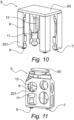
- the punch 201 comprises a support surface intended to cooperate at least at the edge of the bottom 101, for example in its corners as visible on the Figure 10 or on its entire interior perimeter as visible on the Figure 11 .
- This support surface may also include contact zones with other parts of the bottom 101, in particular located towards the center of said bottom 101, in order to distribute the applied force and avoid any deformation.
- the bearing surface of the punch 101 may include several zones coming into contact with the upper face of the bottom 101, against all or part of its surface.
- the punch 201 is extracted from the die 200, making it possible to evacuate this container 110, in particular from below the die 200 as visible on the Figure 7 , in particular towards a conveyor 5 which then takes the containers 110 towards a boxing station (not shown).
- the punch 201 can also be moved to eject the container 110 to another location, such as for example on said conveyor 5.
- the handling station 3 comprises a frame 30 and at least one gripping head 6 mounted movable relative to said frame 30 between said store 2 and the die 200 of said folding station 4.
- Such a chassis 30 is provided with multiple axes, making it possible to move the gripping head 6 in space, according to several degrees of movement.
- the chassis 30 includes a motorization of its own, authorizing the movements necessary to pick up the plates 100 from the magazine 2 by means of the gripping head 6, move said head 6 to the folding station 4, place the plates 100 there and return to the magazine 2 to pick up another plate 100. From then on, so non-exhaustive, the chassis 30 can allow movement according to horizontal translations, longitudinally and transversely, as well as vertical upward and downward movement, as in particular shown schematically on the figures 6 and 7 .
- the downward vertical movement given to the gripping head 6 is used during the folding step.
- said gripping head 6 integrates at least one punch 201. The latter is therefore transported during movements of the gripping head 6 between the folding station 4 and the magazine 2, and vice versa.
- the chassis 30 comprises several guides 31.
- the gripping head 6 is then secured to a guide 31 or mounted on a movable carriage along one of the guides 31, while the other guides can slide relative to each other.
- the chassis 30 comprises a multi-axis robotic arm, at the distal end of which the gripping head 6 is mounted as a tool.
- a robotic arm can also be mounted on guides 31. This arm notably allows better precision when gripping the plates 100 at the level of the magazine 2.
- the gripping head 6 can comprise a structure 60 cooperating in fixing with the chassis 30 and receiving various on-board components, such as the punch 201 which can be fixed on this structure 60.
- said gripping head 6 is equipped with means 7 for gripping and holding said plate 100.
- Such gripping means 7 ensures gripping of a plate 100, in particular at one of its faces, or even a side edge, then maintains it during its transport to the folding station 4, preferably by preventing it from moving in particular during the acceleration and deceleration phases.
- This gripping means 7 can be located at any location on the gripping head 6.
- the gripping means 7 can be mounted on the structure 60 of said gripping head 6.
- the gripping means 7 is integrated into said punch 201, attached to the latter, in particular via the structure 60 of the gripping head 6.
- the gripping means 7 is positioned at the distal end of the punch 201, flush with its bearing surface. Therefore, said bearing surface of the punch 201 is completed by the contact surface of the gripping means 7 against the place 100.
- the bearing surface corresponds to the contact surface between the means 7 of seizure and plate 100.
- the punch 201 can be provided at least partially hollow, delimiting an internal space capable of receiving said gripping means 7 and its fixing with said punch 201 or the structure 60 of the gripping head 6.
- the gripping means 7 can be of any type, for example in the form of needles sufficiently perforating the wall of a plate 100 in order to ensure its grip and retention.
- the input means 7 can also be an electrostatic type system.
- said gripping means 7 comprises at least one suction cup 8, preferably several suction cups 8, acting by suction at said plate 100.
- said suction cup 8 can be arranged so that its suction takes place flush with the bearing surface of said punch 201. Therefore, the bearing surface of the punch 201 is at least partially formed by the surface of suction of said suction cup 8.
- suction cups 8 can be distributed to apply depressions at several locations on the plate 100, in a plane alignment.
- this plane alignment is parallel or substantially parallel to the bearing surface of the punch 200.
- the forming device 1 makes it possible to move the gripping head 6 to the magazine 2, to grip a plate there under the action of the gripping means 7, then to transport it to the folding station 4, to position it on the die 200, to lower the punch 201 and fold the side walls of the plate 100, in order to form the container 110.
- the handling station 3 can provide for detecting the position of each plate 100 in the magazine 2, in order to align the punch 201 with the bottom 101 of the plate 100 to be gripped. This alignment makes it possible to compensate for any lateral or angular shift relative to an optimal position.
- the travel of the handling station 3 is determined in order, upon returning from store 2, to perfectly align the punch 201 with the die 200.
- the invention provides for improving the positioning of the gripped plate 100, when it is positioned with the punch 201 in alignment with the die 200.
- the invention provides for adjusting the position of the bottom 101, to that at least one of its corners is perfectly positioned relative to the die 200, at the time of the descent of the punch 201 into the die 200.
- said gripping means 7 is mounted movable relative to said punch 201.
- the plate 100 is always gripped and held, but the gripping means 7 can move, essentially parallel to the punch 201 and its surface of 'support. The movement of the gripping means 7 then makes it possible to move the plate 100 relative to the punch 201, without moving the latter relative to the frame 30.
- the gripping means 7 is free to move in at least one plane parallel to said bearing surface of said punch 201. In other words, no motorization ensures the movement of the gripping means 7, it is the construction of the gripping means 7 on the gripping head which gives it freedom of movement within a given perimeter.
- the gripping means 7 when the gripping means 7 is integrated into the punch 201, the gripping means 7 is in principle movable in at least the plane corresponding substantially to the plane of the support surface.
- said gripping means 7 is mounted movable in at least two degrees of freedom of movement parallel or substantially parallel to said support surface.
- FIG 8 schematically shows an example of repositioning a corner of the plate 100, carried out according to two orthogonal lateral translations. Only one translation is possible, this can be a result of these orthogonal translations: the corner then moving at an angle.
- freedom of movement can be limited to a few millimeters, of the order of plus or minus five millimeters (+/- 5mm).
- the free movement of the gripping means 7 takes place at a reduced distance, of the order of 2% to 5% relative to the dimensions of the bottom 101, in particular relative to its length or its width.
- said gripping means 7 may comprise an articulated assembly on the gripping head 6, in particular with respect to the structure 60 of said head 6 of grip.
- a joint can be of any type, in particular in the form of a double sliding connection.
- the articulation includes two sliding possibilities, preferably orthogonal to each other, of the gripping means 7.
- said gripping means 7 is articulated according to a ball joint, in particular via a cradle or joints.
- This ball joint can be mounted on the gripping head 6, in particular on its structure 60 and/or on said punch 201.
- the invention can provide for compensating it, in order to obtain a plane or substantially plane mobility of plate 100.
- the joint is offset, in particular at one end of the head 6 gripping, (for example in the upper part), while the gripping means 7 is located at the opposite end (in the lower part). This offset makes it possible to increase the radius of curvature of the movement of the ball joint.
- said gripping means 7 is mounted at the end of a rod 9 mounted in ball joint connection relative to the gripping head 6.
- the gripping means 7 is fixed to the lower end of a rod 9, the upper opposite end of which is ball-jointed on the gripping head 6.
- the gripping means 7 comprises several suction cups 8, they can be mounted independently, each being mobile and free to move in a distinct manner relative to the other suction cups 8.
- the gripping means 7 comprises several suction cups 8
- they can be mounted independently, each being mobile and free to move in a distinct manner relative to the other suction cups 8.
- the suction cups 8 when they are engaged by suction of the plate 100, in particular each suction cup 8 applying suction against an area of the bottom 101, then the latter plays the role of a junction surface, making the suction cups 8 integral with each other in their free movement.
- the suction cups 8 are integral with each other and jointly free to move in said plane.
- the suction cups 8 can be connected together, in particular by a mechanical part, such as a plate or rods.
- the invention provides for limiting the freedom of movement of the gripping means 7 outside the moment of folding, in particular to avoid any movement of the plate 100 gripped during movements of the gripping head 6 by the handling station 3 between store 2 and folding station 4, including when entering a plate 100 at said store 2.
- the forming device 1 comprises means 10 for locking said gripping means 7 relative to the punch 201.
- the locking means 10 make it possible, in an unlocked position, to release the mobility of the gripping means 7.
- the locking means 10 comprise a ring 11, provided to move along the rod 9. Such a ring 11 can therefore move from a high unlocking position to a low locking position, and vice versa. .
- said ring 11 is guided in sliding, in a vertical translation, along an interior wall 202 of said punch 201.
- the ring 11 can therefore only move upwards or downwards, without freedom of movement transversely or horizontally .
- the rod 9 passes through the ring 11 and the through hole has an internal diameter larger than the section of the rod 9, in order to allow freedom of movement of the rod 9 inside the ring 11, and thus the freedom of movement of the input means 7.
- the actuation of the movement of the ring 11 can be carried out by any means of motorization, electric, hydraulic or pneumatic, under the action of a centralized control, managing in particular the operation of the forming device 1.
- the ring 11 is mounted at the movable end of a pneumatic cylinder 12, namely at the level of its piston.
- the opposite end of the cylinder is secured to the gripping head 6.
- the jack 12 can be fixed on the gripping head 6, in particular on an internal wall of the punch 201, as visible in particular on the figures 12 and 13 .
- the deployment of the cylinder 12 ensures the sliding of the ring 11 towards the locking position, and vice versa when it is folded.
- the locking action between the ring 11 and the gripping means 7 is carried out mechanically, by fitting together parts of complementary shapes.
- the ring 11 has a frustoconical section at its interior walls, while the gripping means 7 is provided with a peripheral wall 13 provided as inclined. This peripheral wall 13 then extends in a convergent manner, from the bottom to the top.
- a peripheral wall 13 can be provided on a support part of the suction cup 8.
- the invention also relates to a method of forming containers 110 by folding cardboard plates 100.
- Such a forming process can be adapted for the implementation of the forming device 1 as previously described.
- a plate 100 is gripped. This grip is carried out from the magazine 2 by the gripping head 6.
- the plate 100 is gripped at the level of one face of at least one of its walls, in particular the bottom 101, via at least the gripping means 7.
- the plate 100 is moved towards the folding station 4. This movement can be carried out via handling station 3. During this journey, the plate 100 is held by the gripping means 7.
- the bottom 101 of the plate 100 is positioned in opposite the matrix 200 of said folding station 4.
- the forming process provides, at the time of folding, to adjust the position of said bottom 101 relative to said punch 201, leaving said plate 100 free to move relative to said punch 201.
- This freedom of movement is obtained by means 7 of grip which is mounted movable relative to the punch 201 and in freedom of movement in at least two degrees of freedom, namely at least in a plane parallel or substantially parallel to the bearing surface of said punch 201.
- the plate 100 can adjust naturally so that the folding lines coincide with the nesting of the punch 201 in and against the die 200.
- the plate 100 shifts on its own, to take its place perfectly, in particular under the effect of the lines folding, the prestressing of the material properly orients the plate 100 in its positioning.
- the forming process provides for locking the movement of said plate 100 relative to said punch 201 at least during said movement of said plate 100.
- Locking and unlocking can be done at the input means 7.
- the forming device 2 and the forming method according to the invention allow, through a freedom of movement granted to the gripping means 7, in particular or even only at the time of folding, to reposition the plate 100, in order to compensate a possible discrepancy that occurred previously at the time of entry. It is the cooperation of the action of the punch 201 against the bottom 101 and the matrix 200, which makes it possible to rectify the position of the plate 100 and replace it correctly, in a natural way according to the fold lines.
Landscapes
- Making Paper Articles (AREA)
Description
La présente invention entre dans le domaine du formage par pliage de plaques cartonnées en vue de former des conteneurs, pour y conditionner un ou plusieurs produits.The present invention enters the field of forming by folding cardboard plates with a view to forming containers, for packaging one or more products.
Au sens de la présente invention, le terme « produit » englobe un objet individuel. Un tel produit est un récipient, comme une bouteille ou un flacon, ou bien une canette, ou encore une brique cartonnée. De tels produits peuvent aussi être groupés, positionnés au sein d'une cartonnette (ou « cluster ») et/ou emballés dans un film. Un produit peut être en tout type de matériau, notamment en matériau plastique, en métal ou encore en verre. Un produit peut être rigide ou semi-rigide. Ce récipient est destiné à contenir, de façon non exhaustive, un fluide, un liquide, des poudres ou des granulés, notamment de type agroalimentaire ou cosmétique, ou dédié à l'entretien ou à l'hygiène corporelle. Un produit peut présenter tout type de forme, symétrique ou non, régulière ou irrégulière.For the purposes of the present invention, the term “product” encompasses an individual object. Such a product is a container, such as a bottle or flask, or a can, or even a cardboard brick. Such products can also be grouped, positioned within a carton (or “cluster”) and/or packaged in film. A product can be made of any type of material, in particular plastic, metal or even glass. A product can be rigid or semi-rigid. This container is intended to contain, in a non-exhaustive manner, a fluid, a liquid, powders or granules, in particular of the food or cosmetic type, or dedicated to maintenance or personal hygiene. A product can have any type of shape, symmetrical or not, regular or irregular.
De tels produits sont obtenus le long d'une ligne industrielle de production, subissant plusieurs traitements successifs en traversant des postes dédiés, comme par exemple le soufflage de bouteille ou flacon en matériau plastique, le remplissage et le bouchage, l'étiquetage, ou encore la stérilisation ou la pasteurisation. Une fois traités, les produits finis sont groupés et conditionnés en lots, en particulier à l'intérieur d'un conteneur.Such products are obtained along an industrial production line, undergoing several successive treatments passing through dedicated stations, such as for example the blowing of plastic bottles or vials, filling and capping, labeling, or even sterilization or pasteurization. Once processed, the finished products are grouped and packaged in batches, particularly inside a container.
Un tel conteneur peut se présenter sous la forme d'une caisse cartonnée ou « carton », dédié au conditionnement desdits produits. Un carton présente une forme parallélépipédique rectangle, avec un volume intérieur à même de recevoir un groupe de produits, en quinconce mais préférentiellement disposés en matrice selon des colonnes et des rangées, selon une seule couche ou bien plusieurs couches de produits superposés. Une fois rempli, un carton peut être fermé en partie supérieure ou bien ouvert, formant alors une barquette encore appelée « cartonnette ».Such a container can be in the form of a cardboard box or “cardboard”, dedicated to the packaging of said products. A carton has a rectangular parallelepiped shape, with an interior volume capable of receiving a group of products, in a staggered pattern but preferably arranged in a matrix in columns and rows, in a single layer or several layers of superimposed products. Once filled, a carton can be closed at the top or opened, forming a tray also called a “cartonette”.
De manière connue, la confection automatisée de caisses cartonnées s'effectue par pliage à partir de plaques cartonnées préalablement prédécoupées et préformées, aussi appelées « découpes ».In a known manner, the automated making of cardboard boxes is carried out by folding from previously pre-cut and pre-formed cardboard plates, also called “cuts”.
En référence à la
La plaque 100 cartonnée peut comprendre un couvercle 103, le long d'un bord d'une des parois latérales 102, situé à l'opposé du bord la reliant avec ledit fond 101. Ce couvercle peut aussi comprendre une languette 104, qui sera encollée et rabattue contre l'extérieur d'une paroi latérale 102, en fin de pliage au moment de la fermeture du conteneur 110 ainsi formé une fois des produits introduits à l'intérieur. De plus, de part et d'autre, la plaque 100 cartonnée comprend des rabats, au moins au nombre de quatre de chaque côté : d'une part, des rabats verticaux 105 reliés à chacune des parois latérales 102 et, d'autre part, des rabats horizontaux 106 reliés au fond 101 et au couvercle 103.The
Les différentes parois de la plaque 100 sont reliées par des lignes de pliage, s'étendant selon les arêtes de jonction entre elles. Lesdites lignes de pliage sont préalablement réalisées lors de la découpe de ladite plaque 100 et facilitent les opérations de pliage de chaque paroi par rapport à une autre.The different walls of the
Ceci étant, lors du formage du conteneur 110, la plaque 100 cartonnée est pliée au travers de plusieurs opérations successives. Ces opérations de pliage peuvent être réalisées au travers de postes dédiés et de plusieurs façons différentes.This being said, during the forming of the
L'invention concerne spécifiquement le pliage de plaque cartonnée dit « pliage à fond de matrice ».The invention specifically relates to the folding of cardboard plates known as “die-bottom folding”.
Le pliage à fond de matrice s'effectue par déformation à froid d'un matériau au sein d'une presse, pourvue d'une matrice fixe en alignement de laquelle se déplace un poinçon mobile.Die-bottom bending is carried out by cold deformation of a material within a press, provided with a fixed die in alignment with which a movable punch moves.
En référence aux
Plus précisément, comme visible sur la
On notera que, préalablement au pliage, certaines surfaces des parois de la plaque 100 cartonnée peuvent être encollées, de manière à maintenir les parois entre elles une fois pliées. En outre, c'est la pression appliquée entre la matrice 200 et le poinçon 201, en fin de pliage, qui permet d'assurer la bonne mise en contact entre elles des surfaces encollées.Note that, prior to folding, certain surfaces of the walls of the
Une fois les parois latérales 102 pliées orthogonalement par rapport audit fond 101, le conteneur 110 est formé et ouvert : la plaque 100 présente alors un volume interne, ouvert en partie supérieure. Le poinçon 201 est retiré et le conteneur 110 est extrait de la matrice 200, en vue d'introduire dans son volume intérieur des produits, au cours d'une opération de conditionnement, en particulier d'encaissage. Ensuite, s'il est présent, le couvercle 103 est plié pour refermer le conteneur 110, avec éventuellement un pliage de la languette 104, pour obtenir le conteneur 110 définitif entourant et protégeant les produits qu'il contient.Once the
Une contrainte de ce type de pliage à fond de matrice réside dans l'alignement requis des lignes de pliage avec la matrice et le poinçon, en particulier dans chaque coin. En outre, la précision d'un tel alignement est de l'ordre de quelques millimètres (mm). A défaut, lors du pliage, un décalage risque d'entraîner une déformation préjudiciable du conteneur, voire un déchirement du matériau carton au moment de cette opération, en particulier lors de la descente du poinçon.A constraint of this type of die bottom bending is the required alignment of the fold lines with the die and punch, particularly in each corner. Furthermore, the precision of such alignment is of the order of a few millimeters (mm). Otherwise, during folding, an offset risks causing detrimental deformation of the container, or even tearing of the cardboard material at the time of this operation, in particular when lowering the punch.
En outre, une forme optimale du conteneur, parallélépipédique rectangle, respectant l'orthogonalité de ses parois, est importante et doit être optimale, d'une part, pour l'aspect esthétique et le bon conditionnement des produits, mais surtout d'autre part, lorsque plusieurs caisses doivent être superposées, notamment sur des palettes. Une déformation d'une seule caisse est susceptible de déséquilibrer un empilage de caisses, rendant leur manutention précaire et dangereuse pour les opérateurs.In addition, an optimal shape of the container, rectangular parallelepiped, respecting the orthogonality of its walls, is important and must be optimal, on the one hand, for the aesthetic appearance and the good packaging of the products, but above all on the other hand , when several boxes must be stacked, particularly on pallets. A deformation of a single box is likely to unbalance a stack of boxes, making their handling precarious and dangerous for operators.
Dans ce contexte, le formage de conteneurs par pliage de plaques cartonnées s'effectue au travers d'un dispositif de formage.In this context, the forming of containers by folding cardboard plates is carried out through a forming device.
Un tel dispositif de formage est déjà connu des documents
Avant leur pliage, de telles plaques cartonnées sont disposées au sein d'un magasin, sous forme de pile de plusieurs plaques superposées horizontalement ou verticalement. Les plaques sont extraites l'une après l'autre lors d'une étape de manutention pour les transporter depuis ledit magasin vers ledit poste de pliage.Before folding, such cardboard plates are arranged within a store, in the form of a stack of several plates superimposed horizontally or vertically. The plates are extracted one after the other during a handling step to transport them from said store to said folding station.
Cette étape peut consister à extraire les plaques une par une et les transporter le long de cornières guidées. Toutefois, les cornières sont fixées sur un bâti et conformées complémentairement aux plaques cartonnées et aux conteneurs à former. Cette installation ne permet donc pas de s'adapter à différents formats de plaques cartonnées, ou bien nécessite un temps d'intervention conséquent.This step may consist of extracting the plates one by one and transporting them along guided angles. However, the angles are fixed on a frame and shaped complementary to the cardboard plates and the containers to be formed. This installation therefore does not allow it to be adapted to different formats of cardboard plates, or requires significant intervention time.
A l'heure actuelle, du fait de la diversité de produits à fabriquer, les lignes de production doivent permettre de gérer la fabrication de plusieurs formats différents de produits. Par conséquent, le conditionnement de ces différents formats de produits s'effectue dans des conteneurs distincts, aux dimensions complémentaires auxdits produits, ainsi qu'au nombre de produits à conditionner par conteneur. Une même ligne doit donc être à même de traiter plusieurs formats de plaques en vue d'opérer leur pliage et d'obtenir les conteneurs souhaités, en fonction des produits qu'ils vont recevoir.Currently, due to the diversity of products to be manufactured, production lines must be able to manage the manufacturing of several different product formats. Consequently, the packaging of these different product formats is carried out in separate containers, with dimensions complementary to said products, as well as the number of products to be packaged per container. The same line must therefore be able to process several formats of plates in order to fold them and obtain the desired containers, depending on the products they will receive.
Pour s'adapter plus facilement à plusieurs formats, la manutention de plaques peut s'effectuer par l'intermédiaire d'un poste dédié, monté mobile selon plusieurs axes de déplacement, par l'intermédiaire d'un châssis multi-axes ou d'un bras robotisé multi-axes. De plus, un tel poste de manutention est pourvu d'une tête de préhension à l'unité des plaques.To adapt more easily to several formats, the handling of plates can be carried out via a dedicated station, mounted mobile along several axes of movement, via a multi-axis chassis or a multi-axis robotic arm. In addition, such a handling station is provided with a gripping head for the plates unit.
Cette préhension de chaque plaque peut s'effectuer par différents moyens de saisie, notamment par dépression au moyen de ventouses. Chaque ventouse vient au contact de la face d'une plaque et effectue une aspiration assurant un maintien de ladite plaque en vue de son extraction depuis ledit magasin et son déplacement vers le poste de formage. La préhension par aspiration est conservée au cours de l'opération de pliage, afin de maintenir la plaque par rapport à la matrice et au poinçon. Dès lors, la préhension des ventouses s'effectue au niveau de la face supérieure du fond, qui restera plan au cours du mouvement de la plaque au sein de la matrice sous l'action du déplacement du poinçon.This gripping of each plate can be carried out by different gripping means, in particular by depression using suction cups. Each suction cup comes into contact with the face of a plate and performs suction ensuring said plate is held in place with a view to its extraction from said magazine and its movement towards the forming station. Suction grip is maintained during the bending operation, in order to maintain the plate in relation to the die and the punch. From then on, the gripping of the suction cups is carried out at the level of the upper face of the bottom, which will remain flat during the movement of the plate within the matrix under the action of the movement of the punch.
Une fois le conteneur formé, l'aspiration est arrêtée, en vue de libérer ledit conteneur. Le poinçon est relevé et le conteneur est évacué, par exemple par le dessous de la matrice, notamment par l'intermédiaire d'un convoyeur qui transportera chaque conteneur vers un poste aval d'encaissage des produits, avant de refermer le conteneur. De ce qui précède, afin d'optimiser le dispositif de formage, le poinçon est rapporté sur le poste de manutention, au niveau de la tête de préhension, de façon solidaire avec les ventouses. En particulier, les ventouses se retrouvent en affleurement avec la face inférieure dudit poinçon, pour coopérer avec le fond lors de la préhension. Dès lors, la problématique d'alignement des coins de la plaque cartonnée avec la matrice et le poinçon est considérablement complexifiée. En effet, au début de la préhension de la plaque au niveau du magasin, le poinçon doit être aligné avec les coins de la plaque à saisir, or les plaques ne sont généralement pas parfaitement alignées en superposition dans ledit magasin. Les plaques emmagasinées peuvent présenter un décalage latéral, mais aussi angulaire, les unes par rapport aux autres. Il est donc nécessaire de corriger cet éventuel décalage.Once the container is formed, the suction is stopped, in order to release said container. The punch is raised and the container is evacuated, for example from below the matrix, in particular via a conveyor which will transport each container to a downstream product packing station, before closing the container. From the above, in order to optimize the forming device, the punch is attached to the handling station, at the level of the gripping head, integrally with the suction cups. In particular, the suction cups are found flush with the underside of said punch, to cooperate with the bottom during gripping. Therefore, the problem of aligning the corners of the cardboard plate with the die and the punch is considerably complicated. Indeed, at the start of gripping the plate at the magazine, the punch must be aligned with the corners of the plate to be gripped, but the plates are generally not perfectly aligned in superposition in said magazine. The stored plates can have a lateral, but also angular, offset relative to each other. It is therefore necessary to correct this possible discrepancy.
Une solution connue réside dans une détection d'un décalage, au moment de la préhension dans le magasin, de la position exacte de la plaque à saisir, pour corriger la position de la tête de préhension, en particulier de placer le poinçon en alignement avec les coins du fond.A known solution lies in detecting an offset, at the time of gripping in the magazine, of the exact position of the plate to be gripped, to correct the position of the gripping head, in particular to place the punch in alignment with the bottom corners.
Une solution alternative consiste à corriger la position de la plaque en déplaçant le magasin.An alternative solution is to correct the position of the plate by moving the magazine.
De telles solutions complexifient considérablement le poste de manutention, avec des moyens de détection dédiés et une mobilité accrue de la tête de préhension ou du magasin, augmentant d'autant les coûts inhérents à sa fabrication et le temps nécessaire à sa configuration.Such solutions considerably complicate the handling station, with dedicated detection means and increased mobility of the gripping head or the magazine, thereby increasing the costs inherent in its manufacture and the time required for its configuration.
L'invention a pour but de pallier les inconvénients de l'état de la technique en proposant un dispositif de formage de conteneurs par pliage de plaques cartonnées, permettant de corriger un décalage éventuel entre le poinçon et une plaque, une fois saisie et au moment de l'opération de pliage à fond de matrice.The invention aims to overcome the disadvantages of the state of the art by proposing a device for forming containers by folding cardboard plates, making it possible to correct a possible offset between the punch and a plate, once seized and at the moment of the bending operation at the bottom of the die.
Ledit but est atteint avec un dispositif comprenant les caractéristiques selon la revendication 1 et avec un procédé selon la revendication 8.Said goal is achieved with a device comprising the characteristics according to
En particulier, l'invention prévoit, au niveau de la tête de préhension, de rendre libres en mouvement les ventouses par rapport au poinçon, afin de permettre un ajustement latéral et/ou angulaire de la plaque sous l'action du poinçon lors de sa descente dans la matrice.In particular, the invention provides, at the level of the gripping head, to make the suction cups free to move relative to the punch, in order to allow lateral and/or angular adjustment of the plate under the action of the punch during its descent into the matrix.
Plus précisément, le mouvement des ventouses par rapport au poinçon confère une mobilité au plan de préhension selon au moins deux degrés de libertés parallèlement ou sensiblement parallèlement par rapport au fond de la plaque saisie.More precisely, the movement of the suction cups relative to the punch gives mobility to the gripping plane according to at least two degrees of freedom parallel or substantially parallel to the bottom of the gripped plate.
Ainsi, lors du début de la descente du poinçon, la liberté de mouvement des moyens de saisie autorise un replacement naturel du fond en alignement avec la matrice, sous l'effet de la force appliquée par la coopération entre ladite matrice et ledit poinçon. Ce sont alors les efforts appliqués par la matrice sur la plaque lors du pliage induit par le mouvement du poinçon, qui permet un repositionnement de la plaque grâce à la mobilité du moyen de saisie. Ainsi, la mobilité du moyen de saisie pouvant par exemple être figuré par au moins une ventouse, permet de faire coïncider les lignes de pliage du fond de la plaque avec la matrice, en réduisant les contraintes appliquées au matériau cartonné, pour favoriser un repositionnement plus naturel en alignement desdites lignes de pliage.Thus, when the punch begins to descend, the freedom of movement of the means of seizure allows a natural replacement of the background in alignment with the matrix, under the effect of the force applied by the cooperation between said matrix and said punch. These are then the forces applied by the matrix on the plate during the folding induced by the movement of the punch, which allows repositioning of the plate thanks to the mobility of the gripping means. Thus, the mobility of the gripping means which can for example be represented by at least one suction cup, makes it possible to make the folding lines of the bottom of the plate coincide with the matrix, by reducing the stresses applied to the cardboard material, to promote more repositioning. natural in alignment with said fold lines.
Pour ce faire, l'invention concerne un dispositif de formage de conteneurs par pliage de plaques cartonnées comprenant au moins :
- un poste de pliage de plaques cartonnées, ledit poste de pliage étant pourvu d'au moins une matrice ;
- un poste de manutention desdites plaques depuis un magasin vers ledit poste de pliage,
- ledit poste de manutention comprenant un châssis et au moins une tête de préhension montée mobile par rapport audit châssis entre ledit magasin et la matrice dudit poste de pliage ;
- ladite tête de préhension comprenant un moyen de saisie et de maintien de ladite plaque ;
- ladite tête de préhension comprenant au moins un poinçon conformé complémentairement pour coopérer intérieurement avec ladite matrice, ledit poinçon comprenant une surface d'appui contre le fond de ladite plaque saisie.
- a station for folding cardboard plates, said folding station being provided with at least one die;
- a station for handling said plates from a store to said folding station,
- said handling station comprising a frame and at least one gripping head mounted movable relative to said frame between said magazine and the die of said folding station;
- said gripping head comprising means for gripping and holding said plate;
- said gripping head comprising at least one punch shaped complementary to cooperate internally with said matrix, said punch comprising a bearing surface against the bottom of said gripped plate.
Un tel dispositif de formage est caractérisé en ce que ledit moyen de saisie est monté mobile par rapport audit poinçon et libre en mouvement dans au moins un plan parallèle à ladite surface d'appui dudit poinçon.Such a forming device is characterized in that said gripping means is mounted movable relative to said punch and free to move in at least one plane parallel to said bearing surface of said punch.
Selon des caractéristiques additionnelles, non limitatives, ledit moyen de saisie peut être monté mobile selon au moins deux degrés de liberté de mouvement parallèlement ou sensiblement parallèlement par rapport à ladite surface d'appui.According to additional, non-limiting characteristics, said gripping means can be mounted movable in at least two degrees of freedom of movement parallel or substantially parallel to said support surface.
Le moyen de saisie peut être intégré audit poinçon prévu partiellement creux.The gripping means can be integrated into said partially hollow punch.
Ledit moyen de saisie peut être monté à l'extrémité d'une tige montée en liaison rotule par rapport à la tête de préhension.Said gripping means can be mounted at the end of a rod mounted in a ball joint relative to the gripping head.
Ledit dispositif de formage peut comprendre des moyens de verrouillage dudit moyen de saisie par rapport audit poinçon.Said forming device may comprise means for locking said gripping means relative to said punch.
Ledit moyen de saisie peut comprendre au moins une ventouse agissant par aspiration au niveau de ladite plaque.Said gripping means may comprise at least one suction cup acting by suction at said plate.
Le moyen de saisie peut comprendre plusieurs ventouses libres en déplacement dans ledit plan.The gripping means may comprise several free suction cups moving in said plane.
L'invention concerne encore un procédé de formage de conteneurs par pliage de plaques cartonnées, dans lequel au moins :
- on effectue une saisie d'une plaque ;
- on effectue un déplacement de la plaque saisie vers un poste de pliage et on positionne le fond en vis-à-vis d'une matrice ;
- on effectue un pliage des parois latérales de ladite plaque par descente d'un poinçon au sein de ladite matrice.
- a plate is entered;
- the gripped plate is moved towards a folding station and the bottom is positioned opposite a die;
- the side walls of said plate are folded by lowering a punch into said matrix.
Un tel procédé de formage se caractérise en ce qu'il consiste, au moment du pliage, à ajuster la position dudit fond par rapport audit poinçon, en laissant libre de mouvement ladite plaque par rapport audit poinçon.Such a forming process is characterized in that it consists, at the time of folding, of adjusting the position of said bottom relative to said punch, leaving said plate free to move relative to said punch.
Selon des caractéristiques additionnelles, non limitatives, on peut verrouiller le mouvement de ladite plaque par rapport audit poinçon au moins lors dudit déplacement de ladite plaque.According to additional, non-limiting characteristics, it is possible to lock the movement of said plate relative to said punch at least during said movement of said plate.
Au moment du pliage, on peut déverrouiller le mouvement de ladite plaque.When folding, the movement of said plate can be unlocked.
D'autres caractéristiques et avantages de l'invention ressortiront de la description détaillée qui va suivre des modes de réalisation non limitatifs de l'invention, en référence aux figures annexées, dans lesquelles :
- La
figure 1 représente schématiquement une vue simplifiée en élévation d'un exemple d'une plaque cartonnée, conformée pour un pliage à fond de matrice ; - La
figure 2 représente schématiquement une vue en perspective d'une première étape de pliage à fond de matrice, montrant notamment le positionnement du fond de la plaque en alignement avec le poinçon et la matrice ; - La
figure 3 représente schématiquement une vue similaire à lafigure 2 d'une étape suivante, montrant notamment le pliage des rabats verticaux lors de la descente du poinçon dans la matrice ; - La
figure 4 représente schématiquement une vue similaire à lafigure 3 d'une étape suivante, montrant notamment le pliage des rabats horizontaux et des parois latérales ; - La
figure 5 représente schématiquement une vue similaire à lafigure 4 d'une étape suivante, montrant notamment le conteneur entièrement plié ; - La
figure 6 représente schématiquement une vue simplifiée en élévation d'un mode de réalisation d'un dispositif de formage, montrant notamment le déplacement d'une plaque entre un magasin et le poste de pliage ; - La
figure 7 représente schématiquement une vue simplifiée en coupe verticale de lafigure 6 ; - La
figure 8 représente schématiquement une vue simplifiée en perspective un mode de réalisation, montrant notamment la liberté de mouvement conférée audit coin d'une plaque saisie au moment de son pliage contre la matrice par le poinçon ; - La
figure 9 représente schématiquement une vue simplifiée en coupe verticale d'un détail d'une tête de préhension, montrant notamment une ventouse montée selon une liaison rotule sur ledit poinçon ; - La
figure 10 représente schématiquement une vue en perspective d'un détail d'un premier mode de réalisation dudit dispositif de formage, montrant notamment une tête de préhension équipée de quatre ventouses intégrées à un poinçon formé par quatre piliers en coin ; - La
figure 11 représente schématiquement une vue en perspective d'un détail d'un deuxième mode de réalisation dudit dispositif de formage, montrant notamment une tête de préhension équipée de deux ventouses intégrées à un poinçon avec des faces ajourées ; - La
figure 12 représente schématiquement une vue de côté d'un détail d'une ventouse dans une position déverrouillée, montrant notamment la liberté de mouvement conférée ; - La
figure 13 représente schématiquement une vue similaire à lafigure 12 dans une position verrouillée, montrant notamment la descente d'un organe de verrouillage par actionnement d'un piston.
- There
figure 1 schematically represents a simplified elevation view of an example of a cardboard plate, shaped for folding at the bottom of the die; - There
figure 2 schematically represents a perspective view of a first step of folding at the bottom of the die, showing in particular the positioning of the bottom of the plate in alignment with the punch and the die; - There
Figure 3 schematically represents a view similar to thefigure 2 a following step, showing in particular the folding of the vertical flaps during the descent of the punch into the die; - There
figure 4 schematically represents a view similar to theFigure 3 a next step, showing in particular the folding of the horizontal flaps and the side walls; - There
figure 5 schematically represents a view similar to thefigure 4 a next step, showing in particular the fully folded container; - There
Figure 6 schematically represents a simplified elevation view of one embodiment of a forming device, showing in particular the movement of a plate between a store and the folding station; - There
Figure 7 schematically represents a simplified view in vertical section of theFigure 6 ; - There
figure 8 schematically represents a simplified perspective view of an embodiment, showing in particular the freedom of movement conferred on said corner of a plate gripped at the time of its folding against the die by the punch; - There
Figure 9 schematically represents a simplified view in vertical section of a detail of a gripping head, showing in particular a suction cup mounted in a ball joint connection on said punch; - There
Figure 10 schematically represents a perspective view of a detail of a first embodiment of said forming device, showing in particular a gripping head equipped with four suction cups integrated into a punch formed by four corner pillars; - There
Figure 11 schematically represents a perspective view of a detail of a second embodiment of said forming device, showing in particular a gripping head equipped with two suction cups integrated into a punch with perforated faces; - There
Figure 12 schematically represents a side view of a detail of a suction cup in an unlocked position, showing in particular the freedom of movement conferred; - There
Figure 13 schematically represents a view similar to theFigure 12 in a locked position, showing in particular the descent of a locking member by actuation of a piston.
La présente invention concerne la confection de conteneurs 110.The present invention relates to the making of
Un tel conteneur 110 peut se présenter sous la forme d'une caisse cartonnée ou « carton », dédié au conditionnement de produits. Un carton présente une forme parallélépipédique rectangle, avec un volume intérieur à même de recevoir un groupe de produits, en quinconce mais préférentiellement disposés en matrice selon des colonnes et des rangées, selon une seule couche ou bien plusieurs couches de produits superposés. Un carton peut être fermé en partie supérieure ou bien ouvert, formant alors une barquette encore appelée « cartonnette ».Such a
On notera que le terme « produit » englobe un objet individuel. Un tel produit est un récipient, comme une bouteille ou un flacon, ou bien une canette, ou encore une brique cartonnée. Un produit peut être en tout type de matériau, notamment en matériau plastique, en métal ou encore en verre. Un produit peut être rigide ou semi-rigide. Ce récipient est destiné à contenir, de façon non exhaustive, un fluide, un liquide, des poudres ou des granulés, notamment de type agroalimentaire ou cosmétique, ou dédié à l'entretien ou à l'hygiène corporelle. Un produit peut présenter tout type de forme, symétrique ou non, régulière ou irrégulière.Note that the term “product” encompasses an individual object. Such a product is a container, such as a bottle or flask, or a can, or even a cardboard brick. A product can be made of any type of material, in particular plastic, metal or even glass. A product can be rigid or semi-rigid. This container is intended to contain, in a non-exhaustive manner, a fluid, a liquid, powders or granules, in particular of the food or cosmetic type, or dedicated to maintenance or personal hygiene. A product can have any type of shape, symmetrical or not, regular or irregular.
De tels produits sont obtenus le long d'une ligne industrielle de production, subissant plusieurs traitements successifs en traversant des postes dédiés, comme par exemple le soufflage de bouteille ou flacon en matériau plastique, le remplissage et le bouchage, l'étiquetage, ou encore la stérilisation ou la pasteurisation. Une fois traités, les produits finis sont groupés et conditionnés en lots, en particulier à l'intérieur de conteneurs 110. L'invention vise le formage de conteneurs 110 par pliage de plaques cartonnées 100. Ces plaques cartonnées sont préalablement prédécoupées et préformées, aussi appelées « découpes ». Dans le cadre de l'invention, le terme « plaque » se rapporte à une plaque cartonnée.Such products are obtained along an industrial production line, undergoing several successive treatments passing through dedicated stations, such as for example the blowing of plastic bottles or vials, filling and capping, labeling, or even sterilization or pasteurization. Once processed, the finished products are grouped and packaged in batches, in particular
En particulier, comme évoqué précédemment, une plaque 100 comprend plusieurs parois, dont une paroi qui constituera un fond 101, destiné à recevoir les produits en face supérieure, une fois le conteneur 110 formé. Aux niveaux de deux de ses bords opposés, le fond 101 comprend deux parois latérales 102.In particular, as mentioned previously, a
La plaque 100 peut comprendre un couvercle 103, le long d'un bord d'une des parois latérales 102, situé à l'opposé du bord la reliant avec ledit fond 101.The
Ce couvercle peut aussi comprendre une languette 104, qui sera encollée et rabattue contre l'extérieur d'une paroi latérale 102, en fin de pliage au moment de la fermeture du conteneur 110 ainsi formé.This cover can also include a
De plus, de part et d'autre, la plaque 100 comprend des rabats, au moins au nombre de quatre de chaque côté : d'une part, des rabats verticaux 105 reliés à chacune des parois latérales 102 et, d'autre part, des rabats horizontaux 106 reliés au fond 101 et au couvercle 103.In addition, on either side, the
Les différentes parois de la plaque 100 sont reliées par des lignes de pliage, s'étendant selon les arêtes de jonction entre elles. Lesdites lignes de pliage sont préalablement réalisées lors de la découpe de ladite plaque 100 et facilitent les opérations de pliage de chaque paroi par rapport à une autre.The different walls of the
Ceci étant, lors du formage du conteneur 110, la plaque 100 est pliée au travers de plusieurs opérations successives. En particulier, une première opération de pliage permet de former le conteneur 110 en pliant les parois latérales 102, ainsi que les rabats verticaux 105, puis les rabats horizontaux 106 situés de part et d'autre dudit fond 101. Cette première opération est réalisée par pliage à fond de matrice. Le conteneur 110 est donc formé une fois passé dans la matrice 200.This being said, during the forming of the
Pour ce faire, l'invention concerne un dispositif 1 de formage de conteneurs 110 par pliage de plaques 100 cartonnées.To do this, the invention relates to a
Un tel dispositif 1 de formage est situé le long de la ligne de production, entre un magasin 2 alimenté en plaques 100 et un poste aval, comme par exemple un poste de conditionnement des produits à l'intérieur du conteneur 110. Une fois chargé en produits, le conteneur 110 sera refermé par un poste dédié.Such a forming
On notera que le magasin 2 est alimenté en plaques 100, notamment à partir de fardeaux. Les plaques 100 sont placées sur une zone de réception, en superposition horizontalement ou verticalement, voire de façon inclinée, d'où elles pourront être extraites une par une.Note that
A cet effet, le dispositif 1 de formage comprend un poste 3 de manutention desdites plaques 100 depuis le magasin 2.For this purpose, the forming
Ce poste 3 de manutention assure le transport des plaques 100 en les saisissant une par une, voire plusieurs à la fois, pour les amener vers un poste dédié au pliage.This handling station 3 ensures the transport of the
Ainsi, le dispositif 1 de formage comprend au moins un poste 4 de pliage de plaques 100. Un même poste 4 peut permettre le pliage d'une seule ou de plusieurs plaques 100 à la fois.Thus, the forming
Pour ce faire, ledit poste de pliage est pourvu d'au moins une matrice 200. Une telle matrice 200 comprend une face supérieure de réception d'une plaque 100, sur laquelle la face inférieure de la plaque 100 peut reposer. Cette matrice 200 comprend une forme centrale creuse, dimensionnée complémentairement au fond 101 de la plaque 100, au jeu près de l'épaisseur des parois latérales 102 et des rabats 105,106 une fois repliés. Comme précédemment évoqué, de part et d'autre du creux, la matrice 200 comprend des plots, saillants par rapport à la face supérieure de ladite matrice 200, et conformés pour permettre le pliage successif des rabats verticaux 105, puis des parois latérales 102 et des rabats horizontaux 106 situés inférieurement et reliés au fond 101. En outre, les plots peuvent être prévus arrondis, afin de conférer un pliage des parois de manière progressive, en douceur.To do this, said folding station is provided with at least one
Cette opération de pliage s'effectue sous l'action d'un poinçon 201.This folding operation is carried out under the action of a
Un tel poinçon 201 est conformé complémentairement au creux de la matrice 200, pour permettre d'y coulisser intérieurement, au jeu près susmentionné. Lorsqu'une plaque 100 est positionnée sur la matrice 200, le poinçon 201 vient alors appliquer une force contre le fond 101 de la plaque 100, ledit fond 101 étant pris en sandwich entre ledit poinçon 201 et ladite matrice 200, de manière à induire le pliage des différentes parois. En d'autres termes, le poinçon 201 applique une force conte la matrice 200, qui va contraindre la plaque 100 et la plier. Pour ce faire, le poinçon 201 comprend une surface d'appui destinée à coopérer au moins en bordure du fond 101, par exemple dans ses coins comme visible sur la
Une fois le conteneur 110 formé mais non fermé, le poinçon 201 est extrait de la matrice 200, permettant d'évacuer ce conteneur 110, notamment par le dessous de la matrice 200 comme visible sur la
Le poinçon 201 peut aussi être déplacé pour éjecter le conteneur 110 à un autre emplacement, comme par exemple sur ledit convoyeur 5.The
Préalablement, afin de transporter les plaques depuis le magasin 2 vers le poste 4 de pliage, le poste 3 de manutention comprend un châssis 30 et au moins une tête 6 de préhension montée mobile par rapport audit châssis 30 entre ledit magasin 2 et la matrice 200 dudit poste 4 de pliage.Previously, in order to transport the plates from the
Un tel châssis 30 est prévu multi-axes, permettant de déplacer la tête 6 de préhension dans l'espace, selon plusieurs degrés de mouvement En particulier, le châssis 30 comprend une motorisation qui lui est propre, autorisant les mouvements nécessaires pour prélever les plaques 100 depuis le magasin 2 au moyen de la tête 6 de préhension, déplacer ladite tête 6 jusqu'au poste 4 de pliage, y déposer les plaques 100 et revenir vers le magasin 2 pour y prélever une autre plaque 100. Dès lors, de façon non exhaustive, le châssis 30 peut permettre un mouvement selon des translations horizontales, longitudinalement et transversalement, ainsi qu'un mouvement vertical ascendant et descendant, comme notamment schématisé sur les
En particulier, le mouvement vertical descendant conféré à la tête 6 de préhension est utilisé lors de l'étape de pliage. Ainsi, ladite tête 6 de préhension intègre le au moins un poinçon 201. Ce dernier se retrouve donc transporté lors des déplacements de la tête 6 de préhension entre le poste 4 de pliage et le magasin 2, et inversement.In particular, the downward vertical movement given to the
Selon un mode de réalisation, comme visible sur les
Selon un autre mode de réalisation, le châssis 30 comprend un bras robotisé multi-axes, à l'extrémité distale duquel est monté la tête 6 de préhension en guise d'outil. Un tel bras robotisé peut aussi être monté sur des guides 31. Ce bras permet notamment une meilleure précision lors de la saisie des plaques 100 au niveau du magasin 2. En outre, la tête 6 de préhension peut comprendre une structure 60 coopérant en fixation avec le châssis 30 et recevant différents composants embarqués, comme le poinçon 201 qui peut être fixé sur cette structure 60.According to another embodiment, the
A ce titre, ladite tête 6 de préhension est équipée d'un moyen 7 de saisie et maintien de ladite plaque 100. Un tel moyen 7 de saisie assure la saisie d'une plaque 100, notamment au niveau d'une ses faces, voire un chant latéral, puis la maintient pendant son transport jusqu'au poste 4 de pliage, de préférence en l'empêchant de bouger en particulier lors des phases d'accélération et de décélération.As such, said
Ce moyen 7 de saisie peut être situé à n'importe quel endroit de la tête 6 de préhension. En particulier, le moyen 7 de saisie peut être monté sur la structure 60 de ladite tête 6 de préhension. Préférentiellement, le moyen 7 de saisie est intégré audit poinçon 201, rapporté par rapport à ce dernier, notamment par l'intermédiaire de la structure 60 de la tête 6 de préhension. Dans une telle configuration, le moyen 7 de saisie se retrouve positionné à l'extrémité distale du poinçon 201, en affleurement avec sa surface d'appui. Dès lors, ladite surface d'appui du poinçon 201 est complétée par la surface de contact du moyen 7 de saisie contre la place 100. Selon certains modes de réalisation, la surface d'appui correspond à la surface de contact entre le moyen 7 de saisie et la plaque 100.This gripping means 7 can be located at any location on the
Selon un mode de réalisation, le poinçon 201 peut être prévu au moins partiellement creux, délimitant un espace interne à même de recevoir ledit moyen 7 de saisie et sa fixation avec ledit poinçon 201 ou la structure 60 de la tête 6 de préhension.According to one embodiment, the
Le moyen 7 de saisie peut être de tout type, par exemple sous forme d'aiguilles venant perforer suffisamment la paroi d'une plaque 100 afin d'assurer sa saisie et son maintien. Le moyen 7 de saisie peut aussi être un système de type électrostatique. Préférentiellement, ledit moyen 7 de saisie comprend au moins une ventouse 8, de préférence plusieurs ventouses 8, agissant par aspiration au niveau de ladite plaque 100. Ainsi, la dépression créée permet de saisir fermement la plaque 100. Comme évoqué précédemment, ladite ventouse 8 peut être disposée pour que sa succion s'opère en affleurement avec la surface d'appui dudit poinçon 201. Dès lors, la surface d'appui du poinçon 201 est au moins partiellement formée par la surface de succion de ladite ventouse 8.The gripping means 7 can be of any type, for example in the form of needles sufficiently perforating the wall of a
On notera que, dans le cas de plusieurs ventouses 8, elles peuvent être réparties pour appliquer des dépressions à plusieurs endroits de la plaque 100, dans un alignement plan. En outre, cet alignement plan est parallèle ou sensiblement parallèle à la surface d'appui du poinçon 200.It will be noted that, in the case of
Ainsi, le dispositif 1 de formage permet de déplacer la tête 6 de préhension jusqu'au magasin 2, d'y saisir une plaque sous l'action du moyen 7 de saisie, puis de la transporter jusqu'au poste de 4 de pliage, pour la positionner sur la matrice 200, pour effectuer une descente du poinçon 201 et plier les parois latérales de la plaque 100, afin de former le conteneur 110.Thus, the forming
A ce titre, lors de la préhension, le poste 3 de manutention peut prévoir de détecter la position de chaque plaque 100 dans le magasin 2, afin d'aligner le poinçon 201 avec le fond 101 de la plaque 100 à saisir. Cet alignement permet de compenser un éventuel décalage latéral ou angulaire par rapport à une position optimale.As such, during gripping, the handling station 3 can provide for detecting the position of each
De plus, la course du poste 3 de manutention est déterminée pour, au retour du magasin 2, aligner parfaitement le poinçon 201 avec la matrice 200.In addition, the travel of the handling station 3 is determined in order, upon returning from
Avantageusement, l'invention prévoit d'améliorer le positionnement de la plaque 100 saisie, lorsqu'elle est positionnée avec le poinçon 201 en alignement avec la matrice 200. En particulier, l'invention prévoit d'ajuster la position du fond 101, pour qu'au moins un de ses coins soit parfaitement positionné par rapport à la matrice 200, au moment de la descente du poinçon 201 dans la matrice 200.Advantageously, the invention provides for improving the positioning of the gripped
Pour ce faire, ledit moyen 7 de saisie est monté mobile par rapport audit poinçon 201. En somme, la plaque 100 est toujours saisie et maintenue, mais le moyen 7 de saisie peut bouger, essentiellement parallèlement par rapport au poinçon 201 et sa surface d'appui. Le mouvement du moyen 7 de saisie permet alors de déplacer la plaque 100 par rapport au poinçon 201, sans bouger ce dernier par rapport au châssis 30.To do this, said
De surcroît, le moyen 7 de saisie est libre en mouvement dans au moins un plan parallèle à ladite surface d'appui dudit poinçon 201. En d'autres termes, aucune motorisation n'assure le déplacement du moyen 7 de saisie, c'est la construction du moyen de saisie 7 sur la tête de préhension qui lui confère une liberté de mouvement dans un périmètre donné.In addition, the gripping
En effet, c'est la force appliquée au moment du pliage, lorsque le poinçon 201 coopère avec la matrice 200, sous l'action du mouvement de la tête 6 de préhension, que les contraintes permettent de repositionner la plaque 100, du fait de la liberté de mouvement du moyen 7 de saisie. Ainsi, la plaque 100 se repositionne naturellement, venant se plaquer parfaitement entre le poinçon 201 et la matrice 200 coopérant entre eux.Indeed, it is the force applied at the time of folding, when the
Il est à noter que lorsque le moyen 7 de saisie est intégré au poinçon 201, le moyen 7 de saisie est en principe mobile dans au moins le plan correspondant sensiblement au plan de la surface d'appui.It should be noted that when the gripping
Préférentiellement, ledit moyen 7 de saisie est monté mobile selon au moins deux degrés de liberté de mouvement parallèlement ou sensiblement parallèlement par rapport à ladite surface d'appui.Preferably, said
La
On notera que la liberté de mouvement peut être limitée à quelques millimètres, de l'ordre de plus ou moins cinq millimètres (+/- 5mm). En somme, le déplacement libre du moyen 7 de saisie s'effectue selon une distance réduite, de l'ordre de 2 % à 5 % par rapport aux dimensions du fond 101, notamment par rapport à sa longueur ou sa largeur.Note that freedom of movement can be limited to a few millimeters, of the order of plus or minus five millimeters (+/- 5mm). In short, the free movement of the
Afin de conférer cette liberté de mouvement du moyen du moyen 7 de saisie par rapport au poinçon 201, ledit moyen 7 de saisie peut comprendre un montage articulé sur la tête 6 de préhension, en particulier par rapport à la structure 60 de ladite tête 6 de préhension. Une telle articulation peut être de tout type, notamment sous forme d'une liaison en double glissement. En d'autres termes, l'articulation comprend deux possibilités de coulissements, préférentiellement orthogonaux entre eux, du moyen 7 de saisie.In order to confer this freedom of movement of the means of the
Préférentiellement, ledit moyen 7 de saisie est articulé selon une liaison rotule, notamment par l'intermédiaire d'un berceau ou bien de joints. Cette liaison rotule peut être montée sur la tête 6 de préhension, en particulier sur sa structure 60 et/ou sur ledit poinçon 201.Preferably, said
Un telle liaison rotule conférant un mouvement incurvé, l'invention peut prévoir de le compenser, afin d'obtenir une mobilité plane ou sensiblement plane de plaque 100. Pour ce faire, l'articulation est déportée, notamment à une extrémité de la tête 6 de préhension, (par exemple en partie haute), alors que le moyen 7 de saisie se situe à l'extrémité opposée (en partie basse). Ce déport permet d'augmenter le rayon de courbure du mouvement de la liaison rotule.Such a ball joint conferring a curved movement, the invention can provide for compensating it, in order to obtain a plane or substantially plane mobility of
Préférentiellement, ledit moyen 7 de saisie est montée à l'extrémité d'une tige 9 montée en liaison rotule par rapport à la tête 6 de préhension. En somme, comme visible sur la
Comme évoqué précédemment, lorsque le moyen 7 de saisie comprend plusieurs ventouses 8, elles peuvent être montées indépendantes, chacune étant mobile et en liberté de mouvement de façon distincte par rapport aux autres ventouses 8. Toutefois, quand elles sont en prise par aspiration de la plaque 100, en particulier chaque ventouse 8 appliquant une succion contre une zone du fond 101, alors ce dernier joue le rôle d'une surface de jonction, rendant solidaires les ventouses 8 entre elles dans leur déplacement libre.As mentioned previously, when the gripping
Selon un autre mode de réalisation, les ventouses 8 sont solidaires entre elles et conjointement libres en déplacement dans ledit plan. Pour ce faire, les ventouses 8 peuvent être reliées entre elles, notamment par une pièce mécanique, comme un plateau ou des tiges.According to another embodiment, the
Selon un mode de réalisation, l'invention prévoit de limiter la liberté de mouvement du moyen 7 de saisie en dehors du moment du pliage, en particulier pour éviter tout mouvement de la plaque 100 saisie lors des déplacements de la tête 6 de préhension par le poste 3 de manutention entre le magasin 2 et le poste 4 de pliage, y compris lors de la saisie d'une plaque 100 au niveau dudit magasin 2.According to one embodiment, the invention provides for limiting the freedom of movement of the
Pour ce faire, le dispositif 1 de formage comprend des moyens 10 de verrouillage dudit moyen 7 de saisie par rapport au poinçon 201. Inversement, les moyens 10 de verrouillage permettent, dans une position déverrouillée, de libérer la mobilité du moyen 7 de saisie.To do this, the forming
Selon un mode préférentiel de réalisation, les moyens 10 de verrouillage comprennent une bague 11, prévue mobile le long de la tige 9. Une telle bague 11 peut donc passer d'une position haute en déverrouillage, vers une position basse de verrouillage, et inversement.According to a preferred embodiment, the locking means 10 comprise a
Selon un mode de réalisation, comme visible sur les
En outre, la tige 9 traverse la bague 11 et le trou traversant présente un diamètre interne plus grand que la section de la tige 9, afin d'autoriser la liberté de mouvement de la tige 9 à l'intérieur de la bague 11, et ainsi la liberté de mouvement du moyen 7 de saisie. L'actionnement du déplacement de la bague 11 peut s'effectuer par toute moyen de motorisation, électrique, hydraulique ou pneumatique, sous l'action d'une commande centralisée, gérant notamment le fonctionnement du dispositif 1 de formage. Préférentiellement, la bague 11 est montée à l'extrémité mobile d'un vérin 12 pneumatique, à savoir au niveau de son piston. L'extrémité opposée du vérin est solidarisée de la tête 6 de préhension. Le vérin 12 peut être fixé sur la tête 6 de préhension, en particulier sur une paroi interne du poinçon 201, comme visible notamment sur les
L'invention concerne aussi un procédé de formage de conteneurs 110 par pliage des plaques 100 cartonnées.The invention also relates to a method of forming
Un tel procédé de formage peut être adapté pour la mise en oeuvre du dispositif 1 de formage tel que précédemment décrit.Such a forming process can be adapted for the implementation of the forming
Au cours d'un tel procédé de formage, de façon non limitative, on effectue une saisie d'une plaque 100. Cette saisie s'effectue depuis le magasin 2 par la tête 6 de préhension. En particulier, la saisie de la plaque 100 s'effectue au niveau d'une face d'au moins une de ses parois, notamment le fond 101, par l'intermédiaire d'au moins le moyen 7 de saisie.During such a forming process, in a non-limiting manner, a
Ensuite, on effectue un déplacement la plaque 100 saisie vers le poste 4 de pliage. Ce déplacement peut s'effectuer par le poste 3 de manutention. Pendant ce trajet, la plaque 100 est maintenue par le moyen 7 de saisie.Then, the
Arrivée au niveau du poste 4 de pliage, on positionne le fond 101 de la plaque 100 en vis-à-vis de la matrice 200 dudit poste 4 de pliage.Arriving at the level of
On effectue alors un pliage des parois latérales de ladite plaque 100 par descente d'un poinçon 201 au sein de ladite matrice 200. En particulier, c'est la surface d'appui du poinçon 201, qui applique contre le fond 101 de la plaque 100, une force nécessaire pour contraindre les parois contre les chants intérieurs de la matrice 200 et initier le pliage le long de ligne dédiées à cet effet.We then carry out a folding of the side walls of said
Avantageusement, le procédé de formage prévoit, au moment du pliage, d'ajuster la position dudit fond 101 par rapport audit poinçon 201, en laissant libre de mouvement ladite plaque 100 par rapport audit poinçon 201. Cette liberté de mouvement est obtenue par le moyen 7 de saisie qui est monté mobile par rapport au poinçon 201 et en liberté de mouvement selon au moins deux degrés de liberté, à savoir au moins dans un plan parallèle ou sensiblement parallèle à la surface d'appui dudit poinçon 201. Ainsi, la plaque 100 peut s'ajuster naturellement de sorte que les lignes de pliage coïncident avec l'emboîtement du poinçon 201 dans et contre la matrice 200. La plaque 100 se décale toute seule, pour venir prendre sa place parfaitement, notamment sous l'effet des lignes de pliage, dont la précontrainte du matériau oriente convenablement la plaque 100 dans son positionnement.Advantageously, the forming process provides, at the time of folding, to adjust the position of said
Selon un mode préféré de réalisation, lorsque la plaque 100 est déplacée, on n'autorise pas son mouvement par rapport au poinçon 201 et à la tête 6 de préhension.According to a preferred embodiment, when the
Pour ce faire, le procédé de formage prévoit de verrouiller le mouvement de ladite plaque 100 par rapport audit poinçon 201 au moins lors dudit déplacement de ladite plaque 100.To do this, the forming process provides for locking the movement of said
Inversement, afin d'obtenir la liberté de mouvement, au moment du pliage, on peut déverrouiller le mouvement de ladite plaque 100, comme susmentionné.Conversely, in order to obtain freedom of movement, at the time of folding, the movement of said
Le verrouillage et le déverrouillage peut s'effectue au niveau du moyen 7 de saisie. Ainsi, le dispositif 2 de formage et le procédé de formage selon l'invention permettent, au travers d'une liberté de mouvement octroyé au moyen 7 de saisie, notamment voire uniquement au moment du pliage, de repositionner la plaque 100, afin de compenser un éventuel décalage survenu au préalable au moment de la saisie. C'est la coopération de l'action du poinçon 201 contre le fond 101 et la matrice 200, qui permet de rectifier la position de la plaque 100 et la replacer correctement, de façon naturelle selon les lignes de pliage.Locking and unlocking can be done at the input means 7. Thus, the forming
Claims (10)
- A device (1) for shaping containers (110) by folding cardboard sheets (100), comprising at least the following:- a folding station (4) for folding cardboard sheets (100), said folding station (4) being provided with at least one die (200);- a handling station (3) for handling said sheets (100) from a storage area (2) to said folding station (4),said handling station (3) comprising a frame (30) and at least one gripping head (6) mounted so as to be able to move relative to said frame (30) between said storage area (2) and the die (200) of said folding station (4);said gripping head (6) comprising a grasping means (7) for grasping and holding said sheet (100);said gripping head (6) comprising at least one punch (201) with a complementary shape for interacting with the inside of said die (200), said punch (201) comprising a bearing surface for bearing against the bottom (101) of said grasped sheet (100);characterized in that said grasping means (7) is mounted so as to be able to move relative to said punch (201) and free to move in at least one plane parallel to said bearing surface of said punch (201).
- The shaping device (1) as claimed in the preceding claim, characterized in that said grasping means (7) is mounted so as to be able to move in at least two degrees of freedom of movement parallel or substantially parallel to said bearing surface.
- The shaping device (1) as claimed in either one of the preceding claims, characterized in that the grasping means (7) is incorporated with said punch (201), which is configured to be partially hollow.
- The shaping device (1) as claimed in any one of the preceding claims, characterized in that said grasping means (7) is mounted at the end of a rod (9) mounted in the manner of a ball-jointed connection with respect to the gripping head (6).
- The shaping device (1) as claimed in any one of the preceding claims, characterized in that it comprises locking means (10) for locking said grasping means (7) with respect to said punch (201).
- The shaping device (1) as claimed in the preceding claim, characterized in that said grasping means (7) comprises at least one suction cup (8) acting on said sheet (100).
- The shaping device (1) as claimed in any one of the preceding claims, characterized in that the grasping means (7) comprises multiple suction cups (8) freely displaceable in said plane.
- A method for shaping containers (11) by folding cardboard sheets (100), comprising at least the following:- grasping a sheet (100);- displacing the grasped sheet (100) toward a folding station (4) and positioning the bottom (101) facing a die (200);- folding the side walls of said sheet (100) by lowering a punch (201) within said die (200); characterized in that it consists, at the time of folding, in adjusting the position of said bottom (101) relative to said punch (201), leaving said sheet (100) free to move relative to said punch (201).
- The shaping method as claimed in the preceding claim, characterized in that the movement of said sheet (100) relative to said punch (201) is locked, at least during said displacement of said sheet (100).
- The shaping method as claimed in the preceding claim, characterized in that, at the time of folding, the movement of said sheet (100) is unlocked.
Applications Claiming Priority (2)
| Application Number | Priority Date | Filing Date | Title |
|---|---|---|---|
| FR1914943A FR3105082B1 (en) | 2019-12-18 | 2019-12-18 | Container forming by folding cardboard sheets |
| PCT/EP2020/086840 WO2021123030A1 (en) | 2019-12-18 | 2020-12-17 | Device for forming containers by folding cardboard panels and corresponding method |
Publications (2)
| Publication Number | Publication Date |
|---|---|
| EP4076928A1 EP4076928A1 (en) | 2022-10-26 |
| EP4076928B1 true EP4076928B1 (en) | 2023-10-25 |
Family
ID=69630555
Family Applications (1)
| Application Number | Title | Priority Date | Filing Date |
|---|---|---|---|
| EP20824940.9A Active EP4076928B1 (en) | 2019-12-18 | 2020-12-17 | Device for forming containers by folding cardboard panels and corresponding method |
Country Status (8)
| Country | Link |
|---|---|
| US (1) | US20220410522A1 (en) |
| EP (1) | EP4076928B1 (en) |
| AU (1) | AU2020405320A1 (en) |
| CA (1) | CA3159430A1 (en) |
| ES (1) | ES2968186T3 (en) |
| FR (1) | FR3105082B1 (en) |
| PL (1) | PL4076928T3 (en) |
| WO (1) | WO2021123030A1 (en) |
Family Cites Families (29)
| Publication number | Priority date | Publication date | Assignee | Title |
|---|---|---|---|---|
| US3513757A (en) * | 1967-07-14 | 1970-05-26 | Owens Illinois Inc | Manufacture of open-topped trays |
| US4033242A (en) * | 1975-09-26 | 1977-07-05 | Rice Packaging, Inc. | Carton forming machine |
| GB2093762A (en) * | 1981-03-02 | 1982-09-08 | Metal Box Co Ltd | Forming and/or closing cartons |
| US5352178A (en) * | 1993-02-12 | 1994-10-04 | Douglas Machine Limited Liability Company | Collapsed, tubular carton erecting apparatus |
| US5445590A (en) * | 1993-02-12 | 1995-08-29 | Douglas Machine Limited Liability Company | Collapsed, tubular carton erecting apparatus |
| US5533666A (en) * | 1995-06-12 | 1996-07-09 | Willamette Industries Inc. | Octagonal box structure |
| US6106450A (en) * | 1998-06-01 | 2000-08-22 | Georgia-Pacific Corporation | Apparatus and method for set-up of a non-rectangular container from a knocked-down-flat (KDF) precursor |
| DE29818282U1 (en) * | 1998-10-14 | 1999-01-07 | Mohrbach Maschinenfabrik Gmbh | Device for manufacturing folding boxes |
| US7470226B1 (en) * | 2002-11-26 | 2008-12-30 | R & L Manufacturing | Apparatus and method for forming a container having an enhanced corner support structure |
| US7625329B2 (en) * | 2004-11-02 | 2009-12-01 | Doboy, Inc. | Carton blank transport |
| US7509789B2 (en) * | 2005-08-10 | 2009-03-31 | Visy R & D Pty Ltd | Tray erector |
| US8671654B2 (en) * | 2008-09-12 | 2014-03-18 | H. J. Paul Langen | Method and system for forming containers with corrugated material |
| US8961380B2 (en) * | 2008-09-12 | 2015-02-24 | H. J. Paul Langen | Method and system for forming a carton from a carton blank |
| US8323165B2 (en) * | 2009-09-14 | 2012-12-04 | Thiele Technologies, Inc. | Method for forming a container |
| CA2740243C (en) * | 2010-05-13 | 2017-09-19 | Douglas Machine Inc. | Continuous motion case former |
| DK2450180T3 (en) * | 2010-11-05 | 2013-11-25 | Tavil Indebe S A U | Multi-format box molding machine |
| JP5758644B2 (en) * | 2011-02-14 | 2015-08-05 | 株式会社イシダ | Cardboard box assembly equipment |
| DE102012008817B4 (en) * | 2012-05-07 | 2014-09-04 | Pca Roboter- Und Verpackungstechnik Gmbh | Device and method for securing objects in an open-topped container by means of a flat blank |
| US11433634B2 (en) * | 2012-10-19 | 2022-09-06 | Westrock Shared Services, Llc | Container forming apparatus and method |
| US10987889B2 (en) * | 2015-09-21 | 2021-04-27 | Westrock Shared Services, Llc | Methods and machine for forming a shipping container with an article retaining web |
| NZ732520A (en) * | 2016-06-15 | 2023-06-30 | Visy R & D Pty Ltd | Machine for erecting linerless cartons |
| US10703063B2 (en) * | 2016-08-10 | 2020-07-07 | Dematic Corp. | Container forming system and method |
| US11173686B2 (en) * | 2017-08-25 | 2021-11-16 | Wexxar Packaging, Inc. | Apparatus and method for accurate carton formation |
| CN108688224B (en) * | 2018-04-26 | 2020-02-28 | 杭州中亚机械股份有限公司 | Carton extrusion forming device |
| US11059252B2 (en) * | 2018-11-30 | 2021-07-13 | Westrock Shared Services, Llc | Machine for forming a container from a blank |
| US11772352B2 (en) * | 2020-04-20 | 2023-10-03 | H. J. Paul Langen | Method and apparatus for forming containers |
| NL2025970B1 (en) * | 2020-07-01 | 2022-04-05 | Otium Packaging Tech Bv | Cardboard container |
| US11623422B2 (en) * | 2020-12-22 | 2023-04-11 | Dart Container Corporation | Container forming machine having a blank stacker assembly |
| JP2023103752A (en) * | 2022-01-14 | 2023-07-27 | 株式会社イシダ | Box-making machine and box-making/box-packing system |
-
2019
- 2019-12-18 FR FR1914943A patent/FR3105082B1/en active Active
-
2020
- 2020-12-17 AU AU2020405320A patent/AU2020405320A1/en active Pending
- 2020-12-17 US US17/787,576 patent/US20220410522A1/en active Pending
- 2020-12-17 CA CA3159430A patent/CA3159430A1/en active Pending
- 2020-12-17 WO PCT/EP2020/086840 patent/WO2021123030A1/en unknown
- 2020-12-17 PL PL20824940.9T patent/PL4076928T3/en unknown
- 2020-12-17 ES ES20824940T patent/ES2968186T3/en active Active
- 2020-12-17 EP EP20824940.9A patent/EP4076928B1/en active Active
Also Published As
| Publication number | Publication date |
|---|---|
| FR3105082A1 (en) | 2021-06-25 |
| FR3105082B1 (en) | 2021-11-26 |
| WO2021123030A1 (en) | 2021-06-24 |
| EP4076928A1 (en) | 2022-10-26 |
| PL4076928T3 (en) | 2024-03-25 |
| CA3159430A1 (en) | 2021-06-24 |
| ES2968186T3 (en) | 2024-05-08 |
| US20220410522A1 (en) | 2022-12-29 |
| AU2020405320A1 (en) | 2022-06-23 |
Similar Documents
| Publication | Publication Date | Title |
|---|---|---|
| EP3033223B1 (en) | Method and device for fitting reinforcements on a cardboard packaging cutout | |
| EP0334707B1 (en) | Method and machine for the production of polygonal boxes from sheet material and boxes obtained thereby | |
| EP2007635B1 (en) | Display container with telescopic lid | |
| EP1827983B1 (en) | Method and machine for adjusting the height of crates with square or rectangular cross section, for example for shipping goods | |
| EP3110699B1 (en) | Method and machine for closing square or rectangular cross-section boxes by reducing the height of same to that of the contents thereof | |
| EP3214025B1 (en) | Gripping means for pallets | |
| FR2762295A1 (en) | METHOD AND DEVICE FOR MANUFACTURING A CONTAINER EQUIPPED WITH A LABEL | |
| EP3263469B1 (en) | Machine for extracting, shaping, filling and closing an american box | |
| EP4076928B1 (en) | Device for forming containers by folding cardboard panels and corresponding method | |
| FR2815014A1 (en) | Method for wedging objects in cardboard box utilizes wedging sheet which has central part and foldable side flaps which are folded upwards before forcing wedge into box until in contact with objects' upper surface | |
| EP3771668A2 (en) | Installation and container for packaging containers | |
| FR2926287A1 (en) | Packaging device e.g. gantry robot, for e.g. placing quantity of case on sliding vane, has set of positioning devices arranged to allow placing objects on support elements or object layer in upper part of frame | |
| EP1725393B1 (en) | Machine and method for forming a plate by applying a mandrel | |
| WO2020254464A1 (en) | Device for gripping products, and method for conveying within an industrial production line | |
| EP4031454A1 (en) | Device and method for forming a container by folding | |
| FR3065711A1 (en) | CARTONS FORMING MACHINE | |
| EP0051199B1 (en) | Boxing apparatus for a product arranged in quasi-hemispherical cavities | |
| FR3101858A1 (en) | Folding container forming device and method | |
| FR2657585A1 (en) | METHOD OF PACKAGING STACKED PRODUCTS ON A MEDIUM AND SYSTEM FOR IMPLEMENTING SAID METHOD | |
| WO2002055292A1 (en) | Method and device for forming and folding a cardboard packaging box | |
| WO2018078289A1 (en) | System for holding a row of individual pots, kit of blanks and packing of individual pots | |
| FR2941679A1 (en) | Pallet unloading method for receiving cardboard cases or plastic material thermoformed shells, involves transporting unitary products, and installing unitary conveyor or support with reorientation of products | |
| FR2471317A1 (en) | Bag handling machine fed from magazine - has vacuum pads and hydraulic manipulators to dispense bags from top of line |
Legal Events
| Date | Code | Title | Description |
|---|---|---|---|
| STAA | Information on the status of an ep patent application or granted ep patent |
Free format text: STATUS: UNKNOWN |
|
| STAA | Information on the status of an ep patent application or granted ep patent |
Free format text: STATUS: THE INTERNATIONAL PUBLICATION HAS BEEN MADE |
|
| PUAI | Public reference made under article 153(3) epc to a published international application that has entered the european phase |
Free format text: ORIGINAL CODE: 0009012 |
|
| STAA | Information on the status of an ep patent application or granted ep patent |
Free format text: STATUS: REQUEST FOR EXAMINATION WAS MADE |
|
| 17P | Request for examination filed |
Effective date: 20220706 |
|
| AK | Designated contracting states |
Kind code of ref document: A1 Designated state(s): AL AT BE BG CH CY CZ DE DK EE ES FI FR GB GR HR HU IE IS IT LI LT LU LV MC MK MT NL NO PL PT RO RS SE SI SK SM TR |
|
| DAV | Request for validation of the european patent (deleted) | ||
| DAX | Request for extension of the european patent (deleted) | ||
| GRAP | Despatch of communication of intention to grant a patent |
Free format text: ORIGINAL CODE: EPIDOSNIGR1 |
|
| STAA | Information on the status of an ep patent application or granted ep patent |
Free format text: STATUS: GRANT OF PATENT IS INTENDED |
|
| INTG | Intention to grant announced |
Effective date: 20230519 |
|
| GRAS | Grant fee paid |
Free format text: ORIGINAL CODE: EPIDOSNIGR3 |
|
| GRAA | (expected) grant |
Free format text: ORIGINAL CODE: 0009210 |
|
| STAA | Information on the status of an ep patent application or granted ep patent |
Free format text: STATUS: THE PATENT HAS BEEN GRANTED |
|
| AK | Designated contracting states |
Kind code of ref document: B1 Designated state(s): AL AT BE BG CH CY CZ DE DK EE ES FI FR GB GR HR HU IE IS IT LI LT LU LV MC MK MT NL NO PL PT RO RS SE SI SK SM TR |
|
| REG | Reference to a national code |
Ref country code: GB Ref legal event code: FG4D Free format text: NOT ENGLISH |
|
| REG | Reference to a national code |
Ref country code: CH Ref legal event code: EP |
|
| REG | Reference to a national code |
Ref country code: DE Ref legal event code: R096 Ref document number: 602020019968 Country of ref document: DE |
|
| REG | Reference to a national code |
Ref country code: IE Ref legal event code: FG4D Free format text: LANGUAGE OF EP DOCUMENT: FRENCH |
|
| P01 | Opt-out of the competence of the unified patent court (upc) registered |
Effective date: 20231121 |
|
| REG | Reference to a national code |
Ref country code: NL Ref legal event code: FP |
|
| PGFP | Annual fee paid to national office [announced via postgrant information from national office to epo] |
Ref country code: NL Payment date: 20231219 Year of fee payment: 4 Ref country code: FR Payment date: 20231219 Year of fee payment: 4 Ref country code: DE Payment date: 20231219 Year of fee payment: 4 |
|
| REG | Reference to a national code |
Ref country code: LT Ref legal event code: MG9D |
|
| PGFP | Annual fee paid to national office [announced via postgrant information from national office to epo] |
Ref country code: BE Payment date: 20231219 Year of fee payment: 4 |
|
| REG | Reference to a national code |
Ref country code: AT Ref legal event code: MK05 Ref document number: 1624284 Country of ref document: AT Kind code of ref document: T Effective date: 20231025 |
|
| PG25 | Lapsed in a contracting state [announced via postgrant information from national office to epo] |
Ref country code: GR Free format text: LAPSE BECAUSE OF FAILURE TO SUBMIT A TRANSLATION OF THE DESCRIPTION OR TO PAY THE FEE WITHIN THE PRESCRIBED TIME-LIMIT Effective date: 20240126 |
|
| PG25 | Lapsed in a contracting state [announced via postgrant information from national office to epo] |
Ref country code: IS Free format text: LAPSE BECAUSE OF FAILURE TO SUBMIT A TRANSLATION OF THE DESCRIPTION OR TO PAY THE FEE WITHIN THE PRESCRIBED TIME-LIMIT Effective date: 20240225 |
|
| PG25 | Lapsed in a contracting state [announced via postgrant information from national office to epo] |
Ref country code: LT Free format text: LAPSE BECAUSE OF FAILURE TO SUBMIT A TRANSLATION OF THE DESCRIPTION OR TO PAY THE FEE WITHIN THE PRESCRIBED TIME-LIMIT Effective date: 20231025 |
|
| PGFP | Annual fee paid to national office [announced via postgrant information from national office to epo] |
Ref country code: ES Payment date: 20240105 Year of fee payment: 4 |
|
| PG25 | Lapsed in a contracting state [announced via postgrant information from national office to epo] |
Ref country code: AT Free format text: LAPSE BECAUSE OF FAILURE TO SUBMIT A TRANSLATION OF THE DESCRIPTION OR TO PAY THE FEE WITHIN THE PRESCRIBED TIME-LIMIT Effective date: 20231025 |
|
| PG25 | Lapsed in a contracting state [announced via postgrant information from national office to epo] |
Ref country code: LT Free format text: LAPSE BECAUSE OF FAILURE TO SUBMIT A TRANSLATION OF THE DESCRIPTION OR TO PAY THE FEE WITHIN THE PRESCRIBED TIME-LIMIT Effective date: 20231025 Ref country code: IS Free format text: LAPSE BECAUSE OF FAILURE TO SUBMIT A TRANSLATION OF THE DESCRIPTION OR TO PAY THE FEE WITHIN THE PRESCRIBED TIME-LIMIT Effective date: 20240225 Ref country code: GR Free format text: LAPSE BECAUSE OF FAILURE TO SUBMIT A TRANSLATION OF THE DESCRIPTION OR TO PAY THE FEE WITHIN THE PRESCRIBED TIME-LIMIT Effective date: 20240126 Ref country code: BG Free format text: LAPSE BECAUSE OF FAILURE TO SUBMIT A TRANSLATION OF THE DESCRIPTION OR TO PAY THE FEE WITHIN THE PRESCRIBED TIME-LIMIT Effective date: 20240125 Ref country code: AT Free format text: LAPSE BECAUSE OF FAILURE TO SUBMIT A TRANSLATION OF THE DESCRIPTION OR TO PAY THE FEE WITHIN THE PRESCRIBED TIME-LIMIT Effective date: 20231025 Ref country code: PT Free format text: LAPSE BECAUSE OF FAILURE TO SUBMIT A TRANSLATION OF THE DESCRIPTION OR TO PAY THE FEE WITHIN THE PRESCRIBED TIME-LIMIT Effective date: 20240226 |
|
| REG | Reference to a national code |
Ref country code: ES Ref legal event code: FG2A Ref document number: 2968186 Country of ref document: ES Kind code of ref document: T3 Effective date: 20240508 |