EP4076909B1 - Dekoratives funktionsbauteil mit einer transparenten teilfläche - Google Patents
Dekoratives funktionsbauteil mit einer transparenten teilfläche Download PDFInfo
- Publication number
- EP4076909B1 EP4076909B1 EP20830122.6A EP20830122A EP4076909B1 EP 4076909 B1 EP4076909 B1 EP 4076909B1 EP 20830122 A EP20830122 A EP 20830122A EP 4076909 B1 EP4076909 B1 EP 4076909B1
- Authority
- EP
- European Patent Office
- Prior art keywords
- plastic
- functional component
- cover body
- transparent
- plastic carrier
- Prior art date
- Legal status (The legal status is an assumption and is not a legal conclusion. Google has not performed a legal analysis and makes no representation as to the accuracy of the status listed.)
- Active
Links
Images


Classifications
-
- B—PERFORMING OPERATIONS; TRANSPORTING
- B32—LAYERED PRODUCTS
- B32B—LAYERED PRODUCTS, i.e. PRODUCTS BUILT-UP OF STRATA OF FLAT OR NON-FLAT, e.g. CELLULAR OR HONEYCOMB, FORM
- B32B27/00—Layered products comprising a layer of synthetic resin
- B32B27/06—Layered products comprising a layer of synthetic resin as the main or only constituent of a layer, which is next to another layer of the same or of a different material
- B32B27/08—Layered products comprising a layer of synthetic resin as the main or only constituent of a layer, which is next to another layer of the same or of a different material of synthetic resin
-
- B—PERFORMING OPERATIONS; TRANSPORTING
- B29—WORKING OF PLASTICS; WORKING OF SUBSTANCES IN A PLASTIC STATE IN GENERAL
- B29C—SHAPING OR JOINING OF PLASTICS; SHAPING OF MATERIAL IN A PLASTIC STATE, NOT OTHERWISE PROVIDED FOR; AFTER-TREATMENT OF THE SHAPED PRODUCTS, e.g. REPAIRING
- B29C39/00—Shaping by casting, i.e. introducing the moulding material into a mould or between confining surfaces without significant moulding pressure; Apparatus therefor
- B29C39/02—Shaping by casting, i.e. introducing the moulding material into a mould or between confining surfaces without significant moulding pressure; Apparatus therefor for making articles of definite length, i.e. discrete articles
- B29C39/10—Shaping by casting, i.e. introducing the moulding material into a mould or between confining surfaces without significant moulding pressure; Apparatus therefor for making articles of definite length, i.e. discrete articles incorporating preformed parts or layers, e.g. casting around inserts or for coating articles
-
- B—PERFORMING OPERATIONS; TRANSPORTING
- B29—WORKING OF PLASTICS; WORKING OF SUBSTANCES IN A PLASTIC STATE IN GENERAL
- B29C—SHAPING OR JOINING OF PLASTICS; SHAPING OF MATERIAL IN A PLASTIC STATE, NOT OTHERWISE PROVIDED FOR; AFTER-TREATMENT OF THE SHAPED PRODUCTS, e.g. REPAIRING
- B29C45/00—Injection moulding, i.e. forcing the required volume of moulding material through a nozzle into a closed mould; Apparatus therefor
- B29C45/14—Injection moulding, i.e. forcing the required volume of moulding material through a nozzle into a closed mould; Apparatus therefor incorporating preformed parts or layers, e.g. injection moulding around inserts or for coating articles
- B29C45/14336—Coating a portion of the article, e.g. the edge of the article
-
- B—PERFORMING OPERATIONS; TRANSPORTING
- B29—WORKING OF PLASTICS; WORKING OF SUBSTANCES IN A PLASTIC STATE IN GENERAL
- B29C—SHAPING OR JOINING OF PLASTICS; SHAPING OF MATERIAL IN A PLASTIC STATE, NOT OTHERWISE PROVIDED FOR; AFTER-TREATMENT OF THE SHAPED PRODUCTS, e.g. REPAIRING
- B29C45/00—Injection moulding, i.e. forcing the required volume of moulding material through a nozzle into a closed mould; Apparatus therefor
- B29C45/16—Making multilayered or multicoloured articles
- B29C45/1657—Making multilayered or multicoloured articles using means for adhering or bonding the layers or parts to each other
-
- B—PERFORMING OPERATIONS; TRANSPORTING
- B29—WORKING OF PLASTICS; WORKING OF SUBSTANCES IN A PLASTIC STATE IN GENERAL
- B29C—SHAPING OR JOINING OF PLASTICS; SHAPING OF MATERIAL IN A PLASTIC STATE, NOT OTHERWISE PROVIDED FOR; AFTER-TREATMENT OF THE SHAPED PRODUCTS, e.g. REPAIRING
- B29C45/00—Injection moulding, i.e. forcing the required volume of moulding material through a nozzle into a closed mould; Apparatus therefor
- B29C45/16—Making multilayered or multicoloured articles
- B29C45/1671—Making multilayered or multicoloured articles with an insert
-
- B—PERFORMING OPERATIONS; TRANSPORTING
- B29—WORKING OF PLASTICS; WORKING OF SUBSTANCES IN A PLASTIC STATE IN GENERAL
- B29C—SHAPING OR JOINING OF PLASTICS; SHAPING OF MATERIAL IN A PLASTIC STATE, NOT OTHERWISE PROVIDED FOR; AFTER-TREATMENT OF THE SHAPED PRODUCTS, e.g. REPAIRING
- B29C45/00—Injection moulding, i.e. forcing the required volume of moulding material through a nozzle into a closed mould; Apparatus therefor
- B29C45/16—Making multilayered or multicoloured articles
- B29C45/1679—Making multilayered or multicoloured articles applying surface layers onto injection-moulded substrates inside the mould cavity, e.g. in-mould coating [IMC]
-
- B—PERFORMING OPERATIONS; TRANSPORTING
- B32—LAYERED PRODUCTS
- B32B—LAYERED PRODUCTS, i.e. PRODUCTS BUILT-UP OF STRATA OF FLAT OR NON-FLAT, e.g. CELLULAR OR HONEYCOMB, FORM
- B32B27/00—Layered products comprising a layer of synthetic resin
- B32B27/40—Layered products comprising a layer of synthetic resin comprising polyurethanes
-
- B—PERFORMING OPERATIONS; TRANSPORTING
- B32—LAYERED PRODUCTS
- B32B—LAYERED PRODUCTS, i.e. PRODUCTS BUILT-UP OF STRATA OF FLAT OR NON-FLAT, e.g. CELLULAR OR HONEYCOMB, FORM
- B32B3/00—Layered products comprising a layer with external or internal discontinuities or unevennesses, or a layer of non-planar shape; Layered products comprising a layer having particular features of form
- B32B3/02—Layered products comprising a layer with external or internal discontinuities or unevennesses, or a layer of non-planar shape; Layered products comprising a layer having particular features of form characterised by features of form at particular places, e.g. in edge regions
- B32B3/04—Layered products comprising a layer with external or internal discontinuities or unevennesses, or a layer of non-planar shape; Layered products comprising a layer having particular features of form characterised by features of form at particular places, e.g. in edge regions characterised by at least one layer folded at the edge, e.g. over another layer ; characterised by at least one layer enveloping or enclosing a material
-
- B—PERFORMING OPERATIONS; TRANSPORTING
- B29—WORKING OF PLASTICS; WORKING OF SUBSTANCES IN A PLASTIC STATE IN GENERAL
- B29C—SHAPING OR JOINING OF PLASTICS; SHAPING OF MATERIAL IN A PLASTIC STATE, NOT OTHERWISE PROVIDED FOR; AFTER-TREATMENT OF THE SHAPED PRODUCTS, e.g. REPAIRING
- B29C45/00—Injection moulding, i.e. forcing the required volume of moulding material through a nozzle into a closed mould; Apparatus therefor
- B29C45/0053—Injection moulding, i.e. forcing the required volume of moulding material through a nozzle into a closed mould; Apparatus therefor combined with a final operation, e.g. shaping
- B29C2045/0079—Injection moulding, i.e. forcing the required volume of moulding material through a nozzle into a closed mould; Apparatus therefor combined with a final operation, e.g. shaping applying a coating or covering
-
- B—PERFORMING OPERATIONS; TRANSPORTING
- B29—WORKING OF PLASTICS; WORKING OF SUBSTANCES IN A PLASTIC STATE IN GENERAL
- B29C—SHAPING OR JOINING OF PLASTICS; SHAPING OF MATERIAL IN A PLASTIC STATE, NOT OTHERWISE PROVIDED FOR; AFTER-TREATMENT OF THE SHAPED PRODUCTS, e.g. REPAIRING
- B29C45/00—Injection moulding, i.e. forcing the required volume of moulding material through a nozzle into a closed mould; Apparatus therefor
- B29C45/16—Making multilayered or multicoloured articles
- B29C45/1671—Making multilayered or multicoloured articles with an insert
- B29C2045/1673—Making multilayered or multicoloured articles with an insert injecting the first layer, then feeding the insert, then injecting the second layer
-
- B—PERFORMING OPERATIONS; TRANSPORTING
- B29—WORKING OF PLASTICS; WORKING OF SUBSTANCES IN A PLASTIC STATE IN GENERAL
- B29C—SHAPING OR JOINING OF PLASTICS; SHAPING OF MATERIAL IN A PLASTIC STATE, NOT OTHERWISE PROVIDED FOR; AFTER-TREATMENT OF THE SHAPED PRODUCTS, e.g. REPAIRING
- B29C65/00—Joining or sealing of preformed parts, e.g. welding of plastics materials; Apparatus therefor
- B29C65/56—Joining or sealing of preformed parts, e.g. welding of plastics materials; Apparatus therefor using mechanical means or mechanical connections, e.g. form-fits
-
- B—PERFORMING OPERATIONS; TRANSPORTING
- B29—WORKING OF PLASTICS; WORKING OF SUBSTANCES IN A PLASTIC STATE IN GENERAL
- B29C—SHAPING OR JOINING OF PLASTICS; SHAPING OF MATERIAL IN A PLASTIC STATE, NOT OTHERWISE PROVIDED FOR; AFTER-TREATMENT OF THE SHAPED PRODUCTS, e.g. REPAIRING
- B29C65/00—Joining or sealing of preformed parts, e.g. welding of plastics materials; Apparatus therefor
- B29C65/56—Joining or sealing of preformed parts, e.g. welding of plastics materials; Apparatus therefor using mechanical means or mechanical connections, e.g. form-fits
- B29C65/58—Snap connection
-
- B—PERFORMING OPERATIONS; TRANSPORTING
- B29—WORKING OF PLASTICS; WORKING OF SUBSTANCES IN A PLASTIC STATE IN GENERAL
- B29C—SHAPING OR JOINING OF PLASTICS; SHAPING OF MATERIAL IN A PLASTIC STATE, NOT OTHERWISE PROVIDED FOR; AFTER-TREATMENT OF THE SHAPED PRODUCTS, e.g. REPAIRING
- B29C66/00—General aspects of processes or apparatus for joining preformed parts
- B29C66/01—General aspects dealing with the joint area or with the area to be joined
- B29C66/05—Particular design of joint configurations
- B29C66/10—Particular design of joint configurations particular design of the joint cross-sections
- B29C66/12—Joint cross-sections combining only two joint-segments; Tongue and groove joints; Tenon and mortise joints; Stepped joint cross-sections
- B29C66/124—Tongue and groove joints
- B29C66/1244—Tongue and groove joints characterised by the male part, i.e. the part comprising the tongue
- B29C66/12441—Tongue and groove joints characterised by the male part, i.e. the part comprising the tongue being a single wall
-
- B—PERFORMING OPERATIONS; TRANSPORTING
- B29—WORKING OF PLASTICS; WORKING OF SUBSTANCES IN A PLASTIC STATE IN GENERAL
- B29C—SHAPING OR JOINING OF PLASTICS; SHAPING OF MATERIAL IN A PLASTIC STATE, NOT OTHERWISE PROVIDED FOR; AFTER-TREATMENT OF THE SHAPED PRODUCTS, e.g. REPAIRING
- B29C66/00—General aspects of processes or apparatus for joining preformed parts
- B29C66/50—General aspects of joining tubular articles; General aspects of joining long products, i.e. bars or profiled elements; General aspects of joining single elements to tubular articles, hollow articles or bars; General aspects of joining several hollow-preforms to form hollow or tubular articles
- B29C66/51—Joining tubular articles, profiled elements or bars; Joining single elements to tubular articles, hollow articles or bars; Joining several hollow-preforms to form hollow or tubular articles
- B29C66/53—Joining single elements to tubular articles, hollow articles or bars
- B29C66/532—Joining single elements to the wall of tubular articles, hollow articles or bars
-
- B—PERFORMING OPERATIONS; TRANSPORTING
- B29—WORKING OF PLASTICS; WORKING OF SUBSTANCES IN A PLASTIC STATE IN GENERAL
- B29C—SHAPING OR JOINING OF PLASTICS; SHAPING OF MATERIAL IN A PLASTIC STATE, NOT OTHERWISE PROVIDED FOR; AFTER-TREATMENT OF THE SHAPED PRODUCTS, e.g. REPAIRING
- B29C66/00—General aspects of processes or apparatus for joining preformed parts
- B29C66/70—General aspects of processes or apparatus for joining preformed parts characterised by the composition, physical properties or the structure of the material of the parts to be joined; Joining with non-plastics material
- B29C66/73—General aspects of processes or apparatus for joining preformed parts characterised by the composition, physical properties or the structure of the material of the parts to be joined; Joining with non-plastics material characterised by the intensive physical properties of the material of the parts to be joined, by the optical properties of the material of the parts to be joined, by the extensive physical properties of the parts to be joined, by the state of the material of the parts to be joined or by the material of the parts to be joined being a thermoplastic or a thermoset
- B29C66/733—General aspects of processes or apparatus for joining preformed parts characterised by the composition, physical properties or the structure of the material of the parts to be joined; Joining with non-plastics material characterised by the intensive physical properties of the material of the parts to be joined, by the optical properties of the material of the parts to be joined, by the extensive physical properties of the parts to be joined, by the state of the material of the parts to be joined or by the material of the parts to be joined being a thermoplastic or a thermoset characterised by the optical properties of the material of the parts to be joined, e.g. fluorescence, phosphorescence
- B29C66/7336—General aspects of processes or apparatus for joining preformed parts characterised by the composition, physical properties or the structure of the material of the parts to be joined; Joining with non-plastics material characterised by the intensive physical properties of the material of the parts to be joined, by the optical properties of the material of the parts to be joined, by the extensive physical properties of the parts to be joined, by the state of the material of the parts to be joined or by the material of the parts to be joined being a thermoplastic or a thermoset characterised by the optical properties of the material of the parts to be joined, e.g. fluorescence, phosphorescence at least one of the parts to be joined being opaque, transparent or translucent to visible light
- B29C66/73365—General aspects of processes or apparatus for joining preformed parts characterised by the composition, physical properties or the structure of the material of the parts to be joined; Joining with non-plastics material characterised by the intensive physical properties of the material of the parts to be joined, by the optical properties of the material of the parts to be joined, by the extensive physical properties of the parts to be joined, by the state of the material of the parts to be joined or by the material of the parts to be joined being a thermoplastic or a thermoset characterised by the optical properties of the material of the parts to be joined, e.g. fluorescence, phosphorescence at least one of the parts to be joined being opaque, transparent or translucent to visible light at least one of the parts to be joined being transparent or translucent to visible light
-
- B—PERFORMING OPERATIONS; TRANSPORTING
- B29—WORKING OF PLASTICS; WORKING OF SUBSTANCES IN A PLASTIC STATE IN GENERAL
- B29K—INDEXING SCHEME ASSOCIATED WITH SUBCLASSES B29B, B29C OR B29D, RELATING TO MOULDING MATERIALS OR TO MATERIALS FOR MOULDS, REINFORCEMENTS, FILLERS OR PREFORMED PARTS, e.g. INSERTS
- B29K2075/00—Use of PU, i.e. polyureas or polyurethanes or derivatives thereof, as moulding material
-
- B—PERFORMING OPERATIONS; TRANSPORTING
- B29—WORKING OF PLASTICS; WORKING OF SUBSTANCES IN A PLASTIC STATE IN GENERAL
- B29K—INDEXING SCHEME ASSOCIATED WITH SUBCLASSES B29B, B29C OR B29D, RELATING TO MOULDING MATERIALS OR TO MATERIALS FOR MOULDS, REINFORCEMENTS, FILLERS OR PREFORMED PARTS, e.g. INSERTS
- B29K2995/00—Properties of moulding materials, reinforcements, fillers, preformed parts or moulds
- B29K2995/0018—Properties of moulding materials, reinforcements, fillers, preformed parts or moulds having particular optical properties, e.g. fluorescent or phosphorescent
- B29K2995/0026—Transparent
-
- B—PERFORMING OPERATIONS; TRANSPORTING
- B29—WORKING OF PLASTICS; WORKING OF SUBSTANCES IN A PLASTIC STATE IN GENERAL
- B29L—INDEXING SCHEME ASSOCIATED WITH SUBCLASS B29C, RELATING TO PARTICULAR ARTICLES
- B29L2031/00—Other particular articles
- B29L2031/34—Electrical apparatus, e.g. sparking plugs or parts thereof
- B29L2031/3475—Displays, monitors, TV-sets, computer screens
-
- B—PERFORMING OPERATIONS; TRANSPORTING
- B32—LAYERED PRODUCTS
- B32B—LAYERED PRODUCTS, i.e. PRODUCTS BUILT-UP OF STRATA OF FLAT OR NON-FLAT, e.g. CELLULAR OR HONEYCOMB, FORM
- B32B2307/00—Properties of the layers or laminate
- B32B2307/40—Properties of the layers or laminate having particular optical properties
- B32B2307/412—Transparent
-
- B—PERFORMING OPERATIONS; TRANSPORTING
- B32—LAYERED PRODUCTS
- B32B—LAYERED PRODUCTS, i.e. PRODUCTS BUILT-UP OF STRATA OF FLAT OR NON-FLAT, e.g. CELLULAR OR HONEYCOMB, FORM
- B32B2457/00—Electrical equipment
- B32B2457/20—Displays, e.g. liquid crystal displays, plasma displays
-
- Y—GENERAL TAGGING OF NEW TECHNOLOGICAL DEVELOPMENTS; GENERAL TAGGING OF CROSS-SECTIONAL TECHNOLOGIES SPANNING OVER SEVERAL SECTIONS OF THE IPC; TECHNICAL SUBJECTS COVERED BY FORMER USPC CROSS-REFERENCE ART COLLECTIONS [XRACs] AND DIGESTS
- Y10—TECHNICAL SUBJECTS COVERED BY FORMER USPC
- Y10T—TECHNICAL SUBJECTS COVERED BY FORMER US CLASSIFICATION
- Y10T428/00—Stock material or miscellaneous articles
- Y10T428/24—Structurally defined web or sheet [e.g., overall dimension, etc.]
- Y10T428/24008—Structurally defined web or sheet [e.g., overall dimension, etc.] including fastener for attaching to external surface
- Y10T428/24017—Hook or barb
Definitions
- the invention relates to a decorative functional component with a transparent partial surface, comprising a plastic carrier made of a first plastic material, which has a recess, and a flat cover body made of a transparent second plastic material, which covers or fills the recess of the plastic carrier.
- Components manufactured as two-component injection molded parts are known to contain a transparent partial area or a fully transparent molded part, possibly back-injected behind a decorative film, which is then partially or fully back-injected in a further step. These components contain large mechanical stresses.
- a display device for a terminal of a telecommunications exchange is known. This has a liquid crystal display device which is accommodated in a transparent plastic body and held in a spring-loaded manner by being pressed against opposing stops in both axes by springs.
- a circuit board equipped with the components assigned to the liquid crystal display device is attached to the underside of the plastic body and is connected to the plastic body. The electrical connection between the liquid crystal display device and the circuit board is made by elastic, strip-shaped connectors.
- German disclosure document EN 10 2013 212 445 A1 describes an optical element which comprises an at least partially translucent molded body which has at least one first layer made of a first translucent plastic, wherein the first layer is covered at least in a partial area with a second layer made of a second plastic which is less translucent than the first plastic, and wherein the second layer has at least two locations with different thicknesses.
- a functional component which has a viewing window in a housing.
- the housing and viewing window are designed as a two-component injection-molded part, with adjacent edges of the housing and the viewing window having a tongue and groove connection.
- the plastic material of the viewing window melts slightly in the area of the tongue and groove connection and forms an intimate material bond with the material of the housing.
- Such an intimate material bond is certainly advantageous if the viewing window is to be enclosed in the housing in a liquid-tight manner.
- mechanical stresses are also unavoidable in this case, which affect the optical properties of the viewing window.
- the viewing window is to be positioned in front of a display, the display of which may be impaired as a result.
- a viewing window is recognizable as a special area of a functional component.
- the task was to produce a generic functional component in a simple manner and while largely avoiding the aforementioned disadvantages.
- plastic carrier and the cover body are connected by a loose form fit are joined together and coated by flooding with a low-viscosity hardening transparent plastic.
- a "loose form fit” is understood to mean a form-fitting arrangement of components whose mechanical connection is intentionally designed with play.
- the invention therefore provides, firstly, for mechanically decoupling the two joined components in order to prevent mechanical stresses, and secondly, for over-molding these components in a further step using a transparent elastic mass, preferably a polyurethane, in order to design the surface of the functional component in such a way that the separate arrangement of the two components is optically concealed.
- a transparent elastic mass preferably a polyurethane
- the Figures 1 to 3 illustrate a first embodiment of a functional component.
- This has a plastic carrier 11, which is Figure 1 shown in section.
- the plastic carrier 11 is made of a first It is injection-molded from plastic material and has a recess 13.
- the plastic carrier 11 shown here in sketch form can, for example, be part of a housing or a user interface.
- the cover body 12, 12' is also manufactured by injection molding.
- the cover body 12, 12' consists of a second plastic material and has clip hooks 15, 15', which enable a loose, positive connection of the cover body 12, 12' to the plastic carrier 11.
- the outer distance of the clip hooks 15, 15' is intentionally made smaller than the corresponding cross-section of the recess 13 on the plastic carrier 11, so that the cover body 12, 12' is arranged on the plastic carrier 11 with play after clipping in and is free of mechanical stress.
- the cover body 12, 12' can be provided with a print 53 before assembly.
- both design and color prints as well as functional electrically conductive prints can be printed on the top or bottom of the cover body 12, 12'.
- the cover body 12, 12' can either be made in one piece ( Figure 2a ) or as an over-injected or back-injected film ( Figure 2b ).
- the film can in particular be a functional film 51 which has electrical sensors or display elements not shown here. It is indicated that the functional film 51 has an electrical connection 52.
- the cover body 12 shown is intended to form a transparent window within the plastic carrier 11 and is clipped with its clip hooks 15 into the recess 13 of the plastic carrier 11 ( Figure 3a ).
- the assembled components are then flooded together with a transparent, low-viscosity liquid, which hardens to a transparent plastic layer 14 ( Figure 3b ).
- a transparent, low-viscosity liquid which hardens to a transparent plastic layer 14 ( Figure 3b ).
- polyurethane is used as the flooding material.
- the surfaces of the plastic carrier 11 and the cover body 12 can advantageously be provided with an adhesion promoter beforehand.
- the window created by the cover body 12 within the plastic carrier 11 is preferably intended to allow a view of a display or other display element, which can in particular be part of the functional component.
- a display 18 is attached to the back of the cover body 12, for example by means of an optical adhesive 17 ( Figure 3c ). This step can be omitted if the cover body 12', as shown in the Figure 2b shown, already has a functional film 51 with one or more display elements.
- FIG 4 shows a further embodiment of a functional component, in which a plastic carrier 21 is also initially produced by injection molding, which has a recess 23.
- the inner edge of the recess 23 has a molded-on circumferential web 26 ( Figure 4a ).
- the recess 23 is filled with a second transparent plastic material in an injection mold ( Figure 4b ).
- the second plastic material forms a cover body 22 which fills the recess 23.
- the second plastic material is chemically different from the first plastic material of the plastic carrier 21 and is selected such that the two plastic materials do not can form a material connection with each other.
- the molded circumferential web 26 thus forms a purely positive tongue and groove connection 29 between the plastic carrier 21 and the cover body 22 ( Figure 4b ), without their plastic materials forming a firm bond with one another. In this way, a loose form fit can be achieved in which the cover body 22 sits within the recess 23 of the plastic carrier 21 in a stable manner, but at the same time with play and without tension.
- the components 21, 22 are flooded with a low-viscosity liquid, which then hardens to form a transparent plastic layer 24 ( Figure 4c ).
- the plastic layer 24 stabilizes the arrangement of the cover body 22 on the plastic carrier 21 so that the cover body 22 can no longer move relative to the plastic carrier 21 despite the loose, stress-free connection.
- the plastic layer 24 optically conceals the multi-part design of the underlying surface.
- the Figure 4d again shows the possibility of attaching a display 28 to the underside of the cover body 22 by means of an optical adhesive 27.
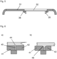
- Figure 5 shows as a variant of the embodiment according to the Figure 3 a plastic carrier 31 with a plane offset.
- the plastic carrier 31 forms a circumferential bent contact web 36 on the edge of its recess, to which the clip hooks 35 of a cover body 32 latch.
- the bent contact web 36 makes it possible to insert the cover body 32 into the recess of the plastic carrier 31 in such a way that the surface of the cover body 32 is flush with the surface of the plastic carrier 31.
- the plastic coating can be compared to the plastic layer 14 in the embodiment according to the Figure 3 be made very thin, since it does not have to enclose a large part of the volume of the cover body 32.
- the Figure 6 shows two examples of a possible transition design between a plastic carrier 41 and a cover body 42.
- a functional component for example, narrow straight gaps 45 ( Figure 6a ) or for components with rounded edges, gaps with transition radii 46 ( Figure 6b ) are created, which are filled during the flooding process by the low-viscosity liquid, which forms the transparent plastic layer 44 after hardening.
Landscapes
- Engineering & Computer Science (AREA)
- Mechanical Engineering (AREA)
- Manufacturing & Machinery (AREA)
- Injection Moulding Of Plastics Or The Like (AREA)
- Laminated Bodies (AREA)
- Casings For Electric Apparatus (AREA)
Description
- Die Erfindung betrifft ein dekoratives Funktionsbauteil mit einer transparenten Teilfläche, aufweisend einen Kunststoffträger aus einem ersten Kunststoffmaterial, der eine Ausnehmung besitzt, und einen flächigen Abdeckkörper aus einem transparenten zweiten Kunststoffmaterial, der die Ausnehmung des Kunststoffträgers abdeckt oder ausfüllt.
- Bekannt sind als Zweikomponentenspritzgussteile gefertigte Bauteile, die einen transparenten Teilbereich oder ein vollflächig transparentes, möglicherweise hinter einer dekorativen Folie hinterspritztes Formteil erhalten, das in einem weiteren Schritt teilweise oder vollflächig hinterspritzt wird. Diese Bauteile enthalten große mechanische Spannungen.
- Aus der deutschen Patentschrift
DE 37 26 225 C1 ist eine Anzeigevorrichtung für ein Endgerät einer Fernmeldevermittlungsanlage bekannt. Diese weist eine Flüssigkristallanzeigevorrichtung auf, welche von einem transparenten Kunststoffkörper aufgenommen und federnd gehalten wird, indem dieselbe in beiden Achsen jeweils durch Federn gegen gegenüberliegende Anschläge gedrückt wird. An der Unterseite des Kunststoffkörpers ist eine mit den der Flüssigkristallanzeigevorrichtung zugeordneten Bauelementen bestückte Leiterplatte angebracht, mit welcher der Kunststoffkörper verbunden ist. Die elektrische Verbindung zwischen Flüssigkristallanzeigevorrichtung und der Leiterplatte erfolgt durch elastische, streifenförmige Verbinder. - Die deutsche Offenlegungsschrift
DE 10 2013 212 445 A1 beschreibt ein optisches Element, das einen zumindest teilweise lichtdurchlässigen Formkörper umfasst, der mindestens eine erste Schicht aus einem ersten lichtdurchlässigen Kunststoff aufweist, wobei die erste Schicht zumindest in einem Teilbereich mit einer zweiten Schicht aus einem zweiten Kunststoff verbunden ist, welcher weniger lichtdurchlässig als der erste Kunststoff ist, und wobei die zweite Schicht mindestens zwei Stellen mit unterschiedlichen Dicken aufweist. - Aus der deutschen Offenlegungsschrift
DE 10 2006 048 550 A1 ist ein Funktionsbauteil bekannt, welches ein Sichtfenster in einem Gehäuse aufweist. Gehäuse und Sichtfenster sind als Zweikomponentenspritzgussteil ausgeführt, wobei aneinander angrenzende Kanten des Gehäuses und des Sichtfensters eine Nut-Feder-Verbindung aufweisen. - Bevorzugt vorgesehen ist dabei, dass das Kunststoffmaterial des Sichtfensters im Bereich der Nut-Feder-Verbindung leicht anschmilzt und einen innigen Materialverbund mit dem Material des Gehäuses eingeht. Ein solch inniger Materialverbund ist durchaus vorteilhaft, wenn das Sichtfenster insbesondere flüssigkeitsdicht in das Gehäuse eingefasst werden soll. Allerdings sind hierbei auch mechanische Spannungen unvermeidlich, welch die optischen Eigenschaften des Sichtfensters beeinflussen.
- Dieses ist insbesondere dann nachteilig, wenn das Sichtfenster vor einem Display angeordnet werden soll, dessen Darstellung hierdurch beeinträchtigt werden kann.
- Für viele Anwendungen ist es zudem unerwünscht, wenn ein Sichtfenster als ein besonderer Bereich eines Funktionsbauteils erkennbar ist.
- Es stellte sich die Aufgabe, ein gattungsgemäßes Funktionsbauteil auf einfache Weise und unter weitgehender Vermeidung der vorgenannten Nachteile zu fertigen.
- Diese Aufgabe wird erfindungsgemäß dadurch gelöst, dass der Kunststoffträger und der Abdeckkörper durch einen losen Formschluss zusammengefügt sind und durch Überfluten gemeinsam mit einem niedrigviskosen aushärtenden transparenten Kunststoff beschichtet sind.
- Unter einem "losen Formschluss" soll hierbei eine formschlüssige Anordnung von Bauteilen verstanden werden, deren mechanische Verbindung absichtlich spielbehaftet ausgestaltet ist.
- Die Erfindung sieht somit vor, erstens, die beiden zusammengefügten Komponenten mechanisch zu entkoppeln, um mechanische Spannungen zu verhindern, und zweitens, diese Komponenten in einem weitere Schritt mittels einer transparenten elastischen Masse, vorzugsweise mit einem Polyurethan, zu überspritzen, um die Oberfläche des Funktionsbauteil so zu gestalten, dass die getrennte Anordnung der beiden Komponenten optisch kaschiert wird. Die sowohl am Kunststoffträger wie auch am Abdeckkörper anhaftende transparente Kunststoffschicht befestigt zudem die beiden Komponenten aneinander, ohne dabei mechanische Spannungen zwischen ihnen aufzubauen.
- Nachfolgend soll die Erfindung anhand einer Zeichnung näher dargestellt und erläutert werden. Es zeigen
- Figur 1
- einen Kunststoffträger,
- Figur 2
- zwei Ausführungsvarianten eines Abdeckkörpers,
- Figur 3
- Montageschritte zur Herstellung eines ersten Funktionsbauteils,
- Figur 4
- Montageschritte zur Herstellung eines zweiten Funktionsbauteils,
- Figur 5
- ein drittes Ausführungsbeispiel eines Funktionsbauteils,
- Figur 6
- Ausführungsdetails des Funktionsbauteils gemäß der
Figur 5 . - Die
Figuren 1 bis 3 verdeutlichen ein erstes Ausführungsbeispiel eines Funktionsbauteils. Dieses weist einen Kunststoffträger 11 auf, der in derFigur 1 im Schnitt dargestellt ist. Der Kunststoffträger 11 ist aus einem ersten Kunststoffmaterial spritzgegossen und weist eine Ausnehmung 13 auf. Der hier skizzenhaft dargestellte Kunststoffträger 11 kann beispielsweise Teil eines Gehäuses oder einer Bedienoberfläche sein. - Ebenfalls durch Spritzgießen hergestellt ist ein transparenter oder teiltransparenter Abdeckkörper 12, 12', der in zwei Ausführungsvarianten in der
Figur 2 dargestellt ist. Der Abdeckkörper 12, 12' besteht aus einem zweiten Kunststoffmaterial und verfügt über Klipshaken 15, 15', die eine lose formschlüssige Verbindung des Abdeckkörpers 12, 12' zum Kunststoffträger 11 ermöglichen. Hierbei ist der äußere Abstand der Klipshaken 15, 15' absichtlich kleiner ausgeführt als der zugehörige Querschnitt der Ausnehmung 13 am Kunststoffträger 11, so dass der Abdeckkörper 12, 12' nach dem Einklipsen spielbehaftet und frei von mechanischen Spannungen am Kunststoffträger 11 angeordnet ist. - Der Abdeckkörper 12, 12' kann bereits vor der Montage mit einer Bedruckung 53 versehen werden. Hierbei können sowohl Design-, Farbdrucke als auch funktionale elektrisch leitende Drucke auf der Oberseite oder Unterseite des Abdeckkörpers 12, 12' aufgedruckt werden.
- Der Abdeckkörper 12, 12' kann entweder einstückig (
Figur 2a ) oder auch als eine überspritzte oder hinterspritzte Folie (Figur 2b ) hergestellt sein. Die Folie kann dabei insbesondere eine funktionale Folie 51 sein, die hier nicht dargestellte elektrische Sensoren oder Anzeigeelemente aufweist. Angedeutet ist, dass die funktionale Folie 51 einen elektrischen Anschluss 52 besitzt. - Der in der
Figur 3 dargestellte Abdeckkörper 12 ist dazu vorgesehen, ein transparentes Fenster innerhalb des Kunststoffträgers 11 auszubilden und wird dazu mit seinen Klipshaken 15 in die Ausnehmung 13 des Kunststoffträgers 11 eingeklipst (Figur 3a ). Danach werden die zusammengefügten Bauteile gemeinsam mittels einer transparenten niedrigviskosen Flüssigkeit überflutet, welche zu einer transparenten Kunststoffschicht 14 aushärtet (Figur 3b ). Vorzugsweise wird als Überflutungsmaterial ein Polyurethan vorgesehen. - Falls das erste Kunststoffmaterial des Kunststoffträgers 11 oder das zweite Kunststoffmaterial des Abdeckkörpers 12 keine Haftung zu der niedrigviskosen Flüssigkeit aufnimmt, können die Oberflächen des Kunststoffträgers 11 und des Abdeckkörpers 12 vorher vorteilhaft mit einem Haftvermittler versehen werden.
- Das durch den Abdeckkörper 12 innerhalb des Kunststoffträgers 11 geschaffene Fenster ist vorzugsweise dazu vorgesehen, den Blick auf ein Display oder ein sonstiges Anzeigeelement zu ermöglichen, das insbesondere Bestandteil des Funktionsbauteils sein kann.
- Zum weiteren Aufbau eines derartigen Funktionsbauteils wird, beispielsweise mittels eines optischen Klebers 17, ein Display 18 an die Rückseite des Abdeckkörpers 12 angebracht (
Figur 3c ). Dieser Schritt kann entfallen, wenn der Abdeckkörper 12', wie in derFigur 2b gezeigt, bereits eine funktionale Folie 51 mit einem oder mehreren Anzeigeelementen aufweist. - Die
Figur 4 zeigt ein weiteres Ausführungsbeispiel eines Funktionsbauteils, bei dem ebenfalls zunächst durch Spritzgießen ein Kunststoffträger 21 hergestellt wird, der eine Ausnehmung 23 aufweist. Zusätzlich weist hier der innere Rand der Ausnehmung 23 einen angeformten umlaufenden Steg 26 auf (Figur 4a ). - Die Ausnehmung 23 wird im folgenden Schritt in einem Spritzgießwerkzeug mit einem zweiten transparenten Kunststoffmaterial gefüllt (
Figur 4b ). Nach dem Aushärten bildet das zweite Kunststoffmaterial einen Abdeckkörper 22 aus, der die Ausnehmung 23 ausfüllt. Das zweite Kunststoffmaterial ist chemisch unterschiedlich zum ersten Kunststoffmaterial des Kunststoffträgers 21, und derart gewählt, dass die beiden Kunststoffmaterialien keine materialschlüssige Verbindung miteinander eingehen können. - Der umspritzte umlaufende Steg 26 bildet so eine rein formschlüssige Nut-Feder-Verbindung 29 zwischen dem Kunststoffträger 21 und dem Abdeckkörper 22 aus (
Figur 4b ), ohne dass deren Kunststoffmaterialien eine feste Verbindung miteinander eingehen. Erreichen lässt sich so ein loser Formschluss, bei dem der Abdeckkörper 22 zwar stabil, aber zugleich spielbehaftet und spannungsfrei innerhalb der Ausnehmung 23 des Kunststoffträgers 21 sitzt. - In einem weiteren Schritt werden die Bauteile 21, 22 mittels einer niedrigviskosen Flüssigkeit überflutet, die danach zu einer transparenten Kunststoffschicht 24 aushärtet (
Figur 4c ). Die Kunststoffschicht 24 stabilisiert die Anordnung des Abdeckkörpers 22 am Kunststoffträger 21, so dass sich der Abdeckkörper 22, trotz der losen, spannungsfreien Anbindung, nicht mehr relativ zum Kunststoffträger 21 verschieben kann. Zugleich kaschiert die Kunststoffschicht 24 optisch die mehrteilige Ausführung der darunterliegenden Oberfläche. - Die
Figur 4d zeigt wiederum die Möglichkeit auf, mittels eines optischen Klebers 27 an der Unterseite des Abdeckkörpers 22 ein Display 28 anzubringen. -
Figur 5 zeigt als Ausführungsvariante zur Ausführungsform gemäß derFigur 3 einen Kunststoffträger 31 mit einen Ebenenversatz. Hierbei bildet der Kunststoffträger 31 am Rand seiner Ausnehmung einen umlaufenden abgekröpften Anlagesteg 36 aus, an dem die Klipshaken 35 eines Abdeckkörpers 32 verrasten. Der abgekröpfte Anlagesteg 36 ermöglicht es, den Abdeckkörper 32 so in die Ausnehmung des Kunststoffträgers 31 einzusetzen, dass die Oberfläche des Abdeckkörpers 32 bündig mit der Oberfläche des Kunststoffträgers 31 abschließt. - Hierdurch kann die, hier nicht dargestellte Kunststoffbeschichtung, im Vergleich zu der Kunststoffschicht 14 bei der Ausführungsform gemäß der
Figur 3 sehr dünn ausgeführt werden, da diese hier nicht einen Großteil des Volumens des Abdeckkörper 32 umschließen muss. - Die
Figur 6 zeigt zwei Beispiele eines möglichen Übergangsdesign zwischen einem Kunststoffträger 41 und einem Abdeckkörper 42. Bei einem Funktionsbauteil können zwischen dem Kunststoffträger 41 und dem Abdeckkörper 42 beispielsweise enge gerade Spalte 45 (Figur 6a ) oder bei Bauteilen mit abgerundeten Rändern Spalte mit Übergangsradien 46 (Figur 6b ) geschaffen werden, die beim Überflutungsvorgang durch die niedrigviskose Flüssigkeit, welche nach dem Aushärten die transparente Kunststoffschicht 44 ausbildet, ausgefüllt werden. -
- 11, 21, 31, 41
- Kunststoffträger
- 12, 12', 22, 32, 42
- Abdeckkörper
- 13, 23
- Ausnehmung
- 14, 24, 44
- transparente(r) Kunststoff(schicht)
- 15, 15', 35
- Klipshaken
- 17, 27
- optischer Kleber
- 18,28
- Display
- 26
- umlaufender Steg
- 29
- Nut-Feder-Verbindung
- 36
- abgekröpfter umlaufender Anlagesteg
- 45
- gerader Spalt
- 46
- Spalte mit Übergangsradien
- 51
- funktionale Folie
- 52
- elektrischer Anschluss
- 53
- Bedruckung
Claims (8)
- Dekoratives Funktionsbauteil mit einer transparenten Teilfläche, aufweisend einen Kunststoffträger (11, 21, 31, 41) aus einem ersten Kunststoffmaterial, der eine Ausnehmung (13, 23) besitzt, und einen flächigen Abdeckkörper (12, 12', 22, 32, 42) aus einem transparenten zweiten Kunststoffmaterial, der die Ausnehmung (13, 23) des Kunststoffträgers (11, 21, 31, 41) abdeckt oder ausfüllt,
dadurch gekennzeichnet,
dass der Kunststoffträger (11, 21, 31, 41) und der Abdeckkörper (12, 12', 22, 32, 42) durch einen losen Formschluss zusammengefügt sind und durch Überfluten gemeinsam mit einem niedrigviskosen aushärtenden transparenten Kunststoff (14, 24, 44) beschichtet sind. - Dekoratives Funktionsbauteil nach Anspruch 1, dadurch gekennzeichnet, dass die formschlüssige Verbindung eine durch Klipshaken (15, 15', 35) hergestellte Rastverbindung ist.
- Dekoratives Funktionsbauteil nach Anspruch 1, dadurch gekennzeichnet, dass die formschlüssige Verbindung eine Nut-Feder-Verbindung (29) ist.
- Dekoratives Funktionsbauteil nach Anspruch 1, dadurch gekennzeichnet, dass das erste und zweite Kunststoffmaterial keine stoffschlüssige Verbindung miteinander eingehen.
- Dekoratives Funktionsbauteil nach Anspruch 1, dadurch gekennzeichnet, dass an der Unterseite des Abdeckkörpers (12, 12', 22, 32, 42) ein Display (18, 28) angeordnet ist.
- Dekoratives Funktionsbauteil nach Anspruch 1, dadurch gekennzeichnet, dass der niedrigviskose transparente Kunststoff (14, 24, 44) ein Polyurethan ist.
- Dekoratives Funktionsbauteil nach Anspruch 1, dadurch gekennzeichnet, das der Kunststoffträger (11, 21, 31, 41) Teil eines Gehäuses ist.
- Dekoratives Funktionsbauteil nach Anspruch 1, dadurch gekennzeichnet, das der Kunststoffträger (11, 21, 31, 41) Teil einer Bedienfläche ist.
Applications Claiming Priority (2)
| Application Number | Priority Date | Filing Date | Title |
|---|---|---|---|
| DE102019008780.1A DE102019008780A1 (de) | 2019-12-18 | 2019-12-18 | Dekoratives Funktionsbauteil mit einer transparenten Teilfläche |
| PCT/EP2020/085911 WO2021122419A1 (de) | 2019-12-18 | 2020-12-14 | Dekoratives funktionsbauteil mit einer transparenten teilfläche |
Publications (2)
| Publication Number | Publication Date |
|---|---|
| EP4076909A1 EP4076909A1 (de) | 2022-10-26 |
| EP4076909B1 true EP4076909B1 (de) | 2024-09-11 |
Family
ID=74104063
Family Applications (1)
| Application Number | Title | Priority Date | Filing Date |
|---|---|---|---|
| EP20830122.6A Active EP4076909B1 (de) | 2019-12-18 | 2020-12-14 | Dekoratives funktionsbauteil mit einer transparenten teilfläche |
Country Status (6)
| Country | Link |
|---|---|
| US (1) | US12030285B2 (de) |
| EP (1) | EP4076909B1 (de) |
| CN (1) | CN114514110A (de) |
| DE (1) | DE102019008780A1 (de) |
| ES (1) | ES2999098T3 (de) |
| WO (1) | WO2021122419A1 (de) |
Families Citing this family (2)
| Publication number | Priority date | Publication date | Assignee | Title |
|---|---|---|---|---|
| FR3132663B1 (fr) * | 2022-02-15 | 2024-10-11 | Faurecia Interieur Ind | Procédé de fabrication d’un élément de garnissage intérieur de véhicule et élément de garnissage intérieur |
| DE102022003605A1 (de) | 2022-09-29 | 2024-04-04 | Kostal Automobil Elektrik Gmbh & Co. Kg | Verfahren zur Herstellung eines Verbundbauteils |
Family Cites Families (11)
| Publication number | Priority date | Publication date | Assignee | Title |
|---|---|---|---|---|
| DE3726225C1 (de) * | 1987-08-07 | 1988-08-04 | Telefonbau & Normalzeit Gmbh | Anzeigevorrichtung mit einer Fluessigkristallanzeige |
| JP2662488B2 (ja) | 1992-12-04 | 1997-10-15 | 株式会社小糸製作所 | 自動車用灯具における前面レンズ脚部とシール溝間のシール構造 |
| FR2731984B1 (fr) | 1995-03-21 | 1997-04-30 | Rapid Sa | Bouchon d'obturation d'une ouverture quelconque et procede de fabrication de ce bouchon |
| GB0521969D0 (en) * | 2005-10-28 | 2005-12-07 | Dow Corning | Joints for multi-component molded articles |
| DE102006048550A1 (de) * | 2006-10-13 | 2008-04-17 | Andreas Stihl Ag & Co. Kg | Behälter eines handgeführten Arbeitsgerätes |
| DE202006018515U1 (de) * | 2006-12-07 | 2007-02-08 | Albea Kunststofftechnik Gmbh | Dekor- und/oder Bedienelement mit einem Gehäuse |
| JP5155826B2 (ja) * | 2007-12-27 | 2013-03-06 | セイコーインスツル株式会社 | 表示装置の製造方法 |
| DE102008058324B4 (de) * | 2008-11-20 | 2014-10-30 | Daimler Ag | Formbauteil aus Kunststoff und Verfahren zu dessen Herstellung |
| US9266310B2 (en) * | 2011-12-16 | 2016-02-23 | Apple Inc. | Methods of joining device structures with adhesive |
| DE102013212445A1 (de) * | 2013-06-27 | 2014-12-31 | Robert Bosch Gmbh | Teilweise getöntes optisches Element und Verfahren zu seiner Herstellung |
| DE102017201660B4 (de) * | 2017-02-02 | 2025-07-17 | Robert Bosch Gmbh | Verfahren zur Herstellung einer leuchtenden 3D-Radarmodulabdeckung und Spritzgieß-Anordnung |
-
2019
- 2019-12-18 DE DE102019008780.1A patent/DE102019008780A1/de active Pending
-
2020
- 2020-12-14 ES ES20830122T patent/ES2999098T3/es active Active
- 2020-12-14 EP EP20830122.6A patent/EP4076909B1/de active Active
- 2020-12-14 CN CN202080069990.8A patent/CN114514110A/zh active Pending
- 2020-12-14 WO PCT/EP2020/085911 patent/WO2021122419A1/de not_active Ceased
-
2022
- 2022-03-10 US US17/691,279 patent/US12030285B2/en active Active
Also Published As
| Publication number | Publication date |
|---|---|
| US20220194065A1 (en) | 2022-06-23 |
| ES2999098T3 (en) | 2025-02-24 |
| EP4076909A1 (de) | 2022-10-26 |
| CN114514110A (zh) | 2022-05-17 |
| DE102019008780A1 (de) | 2021-06-24 |
| WO2021122419A1 (de) | 2021-06-24 |
| US12030285B2 (en) | 2024-07-09 |
Similar Documents
| Publication | Publication Date | Title |
|---|---|---|
| EP1559195A1 (de) | Kapazitiver annäherungs- und/oder berührungssensor sowie elektrisch leitfähiger kunststoffkörper für einen solchen sensor | |
| EP0712265A1 (de) | Baugruppe | |
| DE202010013082U1 (de) | Scheibeneinheit und deren Herstellung | |
| EP0304694A2 (de) | Fest einbaubare Scheibe, insbesondere für Kraftfahrzeuge | |
| EP1055356B1 (de) | Gehäuse | |
| DE10060447B4 (de) | Innenspiegelanordnung | |
| WO2021122419A1 (de) | Dekoratives funktionsbauteil mit einer transparenten teilfläche | |
| DE3442877C2 (de) | ||
| EP0727089B1 (de) | Elektromechanisches bauelement, insbesondere relais, mit dichtem gehäuse | |
| DE19846738A1 (de) | Anbindungselement für Seilzüge | |
| DE9206449U1 (de) | Vorrichtung zum Ein- und Ausschalten elektrischer Verbraucher, insbesondere für Anzeigeinstrumente im Armaturenbrett von Kraftfahrzeugen | |
| DE19705749A1 (de) | Befestigungshalter aus einem Harzpressteil | |
| DE69611589T2 (de) | Durchsichtige Abdeckung für ein Instrumentenbrett,insbesondere für Kraftfahrzeuge | |
| DE2713650A1 (de) | Fuegeverbindung zweier kunststoffteile | |
| DE202007002130U1 (de) | Anschlußstück eines Mikrofons | |
| DE102015002958A1 (de) | Verfahren zum Herstellen eines Kunststoffteils und Kunststoffteil | |
| DE10307532B4 (de) | Anordnung zum Anschluß einer Vakuumleitung an eine Kraftfahrzeugkomponente, insbesondere an einen Bremskraftverstärker | |
| DE4034690A1 (de) | Direkter andruckverbinder | |
| EP0562157A1 (de) | Steckverbindung | |
| EP0498035A1 (de) | Hilfsmittel bei der Herstellung einer Zinkenverbindung | |
| DE102005014961A1 (de) | Befestigung elektronischer Bauteile im Bereich der Windschutzscheibe eines Fahrzeugs | |
| DE4344060C1 (de) | Gehäuse | |
| DE3500785A1 (de) | Mit kunststoff ummantelte spule | |
| DE102019100545A1 (de) | Fixier- und rückhaltestift | |
| DE102004010506A1 (de) | Vorrichtung und Verfahren für eine elektrische Anbindung von Stellgliedern oder Sensorelementen an Leiterbahnen |
Legal Events
| Date | Code | Title | Description |
|---|---|---|---|
| STAA | Information on the status of an ep patent application or granted ep patent |
Free format text: STATUS: UNKNOWN |
|
| STAA | Information on the status of an ep patent application or granted ep patent |
Free format text: STATUS: THE INTERNATIONAL PUBLICATION HAS BEEN MADE |
|
| PUAI | Public reference made under article 153(3) epc to a published international application that has entered the european phase |
Free format text: ORIGINAL CODE: 0009012 |
|
| STAA | Information on the status of an ep patent application or granted ep patent |
Free format text: STATUS: REQUEST FOR EXAMINATION WAS MADE |
|
| 17P | Request for examination filed |
Effective date: 20220614 |
|
| AK | Designated contracting states |
Kind code of ref document: A1 Designated state(s): AL AT BE BG CH CY CZ DE DK EE ES FI FR GB GR HR HU IE IS IT LI LT LU LV MC MK MT NL NO PL PT RO RS SE SI SK SM TR |
|
| DAV | Request for validation of the european patent (deleted) | ||
| DAX | Request for extension of the european patent (deleted) | ||
| GRAP | Despatch of communication of intention to grant a patent |
Free format text: ORIGINAL CODE: EPIDOSNIGR1 |
|
| STAA | Information on the status of an ep patent application or granted ep patent |
Free format text: STATUS: GRANT OF PATENT IS INTENDED |
|
| INTG | Intention to grant announced |
Effective date: 20240617 |
|
| GRAS | Grant fee paid |
Free format text: ORIGINAL CODE: EPIDOSNIGR3 |
|
| GRAA | (expected) grant |
Free format text: ORIGINAL CODE: 0009210 |
|
| STAA | Information on the status of an ep patent application or granted ep patent |
Free format text: STATUS: THE PATENT HAS BEEN GRANTED |
|
| AK | Designated contracting states |
Kind code of ref document: B1 Designated state(s): AL AT BE BG CH CY CZ DE DK EE ES FI FR GB GR HR HU IE IS IT LI LT LU LV MC MK MT NL NO PL PT RO RS SE SI SK SM TR |
|
| REG | Reference to a national code |
Ref country code: GB Ref legal event code: FG4D Free format text: NOT ENGLISH |
|
| REG | Reference to a national code |
Ref country code: CH Ref legal event code: EP |
|
| REG | Reference to a national code |
Ref country code: DE Ref legal event code: R096 Ref document number: 502020009230 Country of ref document: DE |
|
| REG | Reference to a national code |
Ref country code: IE Ref legal event code: FG4D Free format text: LANGUAGE OF EP DOCUMENT: GERMAN |
|
| REG | Reference to a national code |
Ref country code: SE Ref legal event code: TRGR |
|
| REG | Reference to a national code |
Ref country code: LT Ref legal event code: MG9D |
|
| PG25 | Lapsed in a contracting state [announced via postgrant information from national office to epo] |
Ref country code: NO Free format text: LAPSE BECAUSE OF FAILURE TO SUBMIT A TRANSLATION OF THE DESCRIPTION OR TO PAY THE FEE WITHIN THE PRESCRIBED TIME-LIMIT Effective date: 20241211 |
|
| REG | Reference to a national code |
Ref country code: NL Ref legal event code: MP Effective date: 20240911 |
|
| PG25 | Lapsed in a contracting state [announced via postgrant information from national office to epo] |
Ref country code: GR Free format text: LAPSE BECAUSE OF FAILURE TO SUBMIT A TRANSLATION OF THE DESCRIPTION OR TO PAY THE FEE WITHIN THE PRESCRIBED TIME-LIMIT Effective date: 20241212 Ref country code: FI Free format text: LAPSE BECAUSE OF FAILURE TO SUBMIT A TRANSLATION OF THE DESCRIPTION OR TO PAY THE FEE WITHIN THE PRESCRIBED TIME-LIMIT Effective date: 20240911 |
|
| PG25 | Lapsed in a contracting state [announced via postgrant information from national office to epo] |
Ref country code: BG Free format text: LAPSE BECAUSE OF FAILURE TO SUBMIT A TRANSLATION OF THE DESCRIPTION OR TO PAY THE FEE WITHIN THE PRESCRIBED TIME-LIMIT Effective date: 20240911 |
|
| PG25 | Lapsed in a contracting state [announced via postgrant information from national office to epo] |
Ref country code: LV Free format text: LAPSE BECAUSE OF FAILURE TO SUBMIT A TRANSLATION OF THE DESCRIPTION OR TO PAY THE FEE WITHIN THE PRESCRIBED TIME-LIMIT Effective date: 20240911 |
|
| PG25 | Lapsed in a contracting state [announced via postgrant information from national office to epo] |
Ref country code: HR Free format text: LAPSE BECAUSE OF FAILURE TO SUBMIT A TRANSLATION OF THE DESCRIPTION OR TO PAY THE FEE WITHIN THE PRESCRIBED TIME-LIMIT Effective date: 20240911 |
|
| PG25 | Lapsed in a contracting state [announced via postgrant information from national office to epo] |
Ref country code: RS Free format text: LAPSE BECAUSE OF FAILURE TO SUBMIT A TRANSLATION OF THE DESCRIPTION OR TO PAY THE FEE WITHIN THE PRESCRIBED TIME-LIMIT Effective date: 20241211 |
|
| PG25 | Lapsed in a contracting state [announced via postgrant information from national office to epo] |
Ref country code: RS Free format text: LAPSE BECAUSE OF FAILURE TO SUBMIT A TRANSLATION OF THE DESCRIPTION OR TO PAY THE FEE WITHIN THE PRESCRIBED TIME-LIMIT Effective date: 20241211 Ref country code: NO Free format text: LAPSE BECAUSE OF FAILURE TO SUBMIT A TRANSLATION OF THE DESCRIPTION OR TO PAY THE FEE WITHIN THE PRESCRIBED TIME-LIMIT Effective date: 20241211 Ref country code: LV Free format text: LAPSE BECAUSE OF FAILURE TO SUBMIT A TRANSLATION OF THE DESCRIPTION OR TO PAY THE FEE WITHIN THE PRESCRIBED TIME-LIMIT Effective date: 20240911 Ref country code: HR Free format text: LAPSE BECAUSE OF FAILURE TO SUBMIT A TRANSLATION OF THE DESCRIPTION OR TO PAY THE FEE WITHIN THE PRESCRIBED TIME-LIMIT Effective date: 20240911 Ref country code: GR Free format text: LAPSE BECAUSE OF FAILURE TO SUBMIT A TRANSLATION OF THE DESCRIPTION OR TO PAY THE FEE WITHIN THE PRESCRIBED TIME-LIMIT Effective date: 20241212 Ref country code: FI Free format text: LAPSE BECAUSE OF FAILURE TO SUBMIT A TRANSLATION OF THE DESCRIPTION OR TO PAY THE FEE WITHIN THE PRESCRIBED TIME-LIMIT Effective date: 20240911 Ref country code: BG Free format text: LAPSE BECAUSE OF FAILURE TO SUBMIT A TRANSLATION OF THE DESCRIPTION OR TO PAY THE FEE WITHIN THE PRESCRIBED TIME-LIMIT Effective date: 20240911 |
|
| PG25 | Lapsed in a contracting state [announced via postgrant information from national office to epo] |
Ref country code: NL Free format text: LAPSE BECAUSE OF FAILURE TO SUBMIT A TRANSLATION OF THE DESCRIPTION OR TO PAY THE FEE WITHIN THE PRESCRIBED TIME-LIMIT Effective date: 20240911 |
|
| REG | Reference to a national code |
Ref country code: ES Ref legal event code: FG2A Ref document number: 2999098 Country of ref document: ES Kind code of ref document: T3 Effective date: 20250224 |
|
| PG25 | Lapsed in a contracting state [announced via postgrant information from national office to epo] |
Ref country code: IS Free format text: LAPSE BECAUSE OF FAILURE TO SUBMIT A TRANSLATION OF THE DESCRIPTION OR TO PAY THE FEE WITHIN THE PRESCRIBED TIME-LIMIT Effective date: 20250111 Ref country code: PT Free format text: LAPSE BECAUSE OF FAILURE TO SUBMIT A TRANSLATION OF THE DESCRIPTION OR TO PAY THE FEE WITHIN THE PRESCRIBED TIME-LIMIT Effective date: 20250113 |
|
| PG25 | Lapsed in a contracting state [announced via postgrant information from national office to epo] |
Ref country code: SM Free format text: LAPSE BECAUSE OF FAILURE TO SUBMIT A TRANSLATION OF THE DESCRIPTION OR TO PAY THE FEE WITHIN THE PRESCRIBED TIME-LIMIT Effective date: 20240911 Ref country code: RO Free format text: LAPSE BECAUSE OF FAILURE TO SUBMIT A TRANSLATION OF THE DESCRIPTION OR TO PAY THE FEE WITHIN THE PRESCRIBED TIME-LIMIT Effective date: 20240911 |
|
| PG25 | Lapsed in a contracting state [announced via postgrant information from national office to epo] |
Ref country code: EE Free format text: LAPSE BECAUSE OF FAILURE TO SUBMIT A TRANSLATION OF THE DESCRIPTION OR TO PAY THE FEE WITHIN THE PRESCRIBED TIME-LIMIT Effective date: 20240911 |
|
| PG25 | Lapsed in a contracting state [announced via postgrant information from national office to epo] |
Ref country code: PL Free format text: LAPSE BECAUSE OF FAILURE TO SUBMIT A TRANSLATION OF THE DESCRIPTION OR TO PAY THE FEE WITHIN THE PRESCRIBED TIME-LIMIT Effective date: 20240911 |
|
| PG25 | Lapsed in a contracting state [announced via postgrant information from national office to epo] |
Ref country code: SK Free format text: LAPSE BECAUSE OF FAILURE TO SUBMIT A TRANSLATION OF THE DESCRIPTION OR TO PAY THE FEE WITHIN THE PRESCRIBED TIME-LIMIT Effective date: 20240911 |
|
| REG | Reference to a national code |
Ref country code: DE Ref legal event code: R097 Ref document number: 502020009230 Country of ref document: DE |
|
| PG25 | Lapsed in a contracting state [announced via postgrant information from national office to epo] |
Ref country code: MC Free format text: LAPSE BECAUSE OF FAILURE TO SUBMIT A TRANSLATION OF THE DESCRIPTION OR TO PAY THE FEE WITHIN THE PRESCRIBED TIME-LIMIT Effective date: 20240911 |
|
| PG25 | Lapsed in a contracting state [announced via postgrant information from national office to epo] |
Ref country code: DK Free format text: LAPSE BECAUSE OF FAILURE TO SUBMIT A TRANSLATION OF THE DESCRIPTION OR TO PAY THE FEE WITHIN THE PRESCRIBED TIME-LIMIT Effective date: 20240911 |
|
| PLBE | No opposition filed within time limit |
Free format text: ORIGINAL CODE: 0009261 |
|
| STAA | Information on the status of an ep patent application or granted ep patent |
Free format text: STATUS: NO OPPOSITION FILED WITHIN TIME LIMIT |
|
| REG | Reference to a national code |
Ref country code: CH Ref legal event code: PL |
|
| PG25 | Lapsed in a contracting state [announced via postgrant information from national office to epo] |
Ref country code: LU Free format text: LAPSE BECAUSE OF NON-PAYMENT OF DUE FEES Effective date: 20241214 |
|
| 26N | No opposition filed |
Effective date: 20250612 |
|
| REG | Reference to a national code |
Ref country code: BE Ref legal event code: MM Effective date: 20241231 |
|
| PG25 | Lapsed in a contracting state [announced via postgrant information from national office to epo] |
Ref country code: BE Free format text: LAPSE BECAUSE OF NON-PAYMENT OF DUE FEES Effective date: 20241231 |
|
| PG25 | Lapsed in a contracting state [announced via postgrant information from national office to epo] |
Ref country code: CH Free format text: LAPSE BECAUSE OF NON-PAYMENT OF DUE FEES Effective date: 20241231 |
|
| PG25 | Lapsed in a contracting state [announced via postgrant information from national office to epo] |
Ref country code: IE Free format text: LAPSE BECAUSE OF NON-PAYMENT OF DUE FEES Effective date: 20241214 |
|
| PGFP | Annual fee paid to national office [announced via postgrant information from national office to epo] |
Ref country code: DE Payment date: 20251217 Year of fee payment: 6 |
|
| PGFP | Annual fee paid to national office [announced via postgrant information from national office to epo] |
Ref country code: GB Payment date: 20251218 Year of fee payment: 6 |
|
| PGFP | Annual fee paid to national office [announced via postgrant information from national office to epo] |
Ref country code: AT Payment date: 20260113 Year of fee payment: 5 |
|
| PGFP | Annual fee paid to national office [announced via postgrant information from national office to epo] |
Ref country code: IT Payment date: 20251205 Year of fee payment: 6 |
|
| PGFP | Annual fee paid to national office [announced via postgrant information from national office to epo] |
Ref country code: FR Payment date: 20251230 Year of fee payment: 6 |
|
| PGFP | Annual fee paid to national office [announced via postgrant information from national office to epo] |
Ref country code: SE Payment date: 20251210 Year of fee payment: 6 |
|
| PGFP | Annual fee paid to national office [announced via postgrant information from national office to epo] |
Ref country code: CZ Payment date: 20251121 Year of fee payment: 6 |
|
| PGFP | Annual fee paid to national office [announced via postgrant information from national office to epo] |
Ref country code: ES Payment date: 20260122 Year of fee payment: 6 |