EP4076872B1 - Ensemble formant porte permettant un montage ameliore sur les parois d'une enceinte, et enceinte comportant un tel ensemble de porte - Google Patents
Ensemble formant porte permettant un montage ameliore sur les parois d'une enceinte, et enceinte comportant un tel ensemble de porte Download PDFInfo
- Publication number
- EP4076872B1 EP4076872B1 EP20845600.4A EP20845600A EP4076872B1 EP 4076872 B1 EP4076872 B1 EP 4076872B1 EP 20845600 A EP20845600 A EP 20845600A EP 4076872 B1 EP4076872 B1 EP 4076872B1
- Authority
- EP
- European Patent Office
- Prior art keywords
- enclosure
- door assembly
- wall portion
- flange
- wall
- Prior art date
- Legal status (The legal status is an assumption and is not a legal conclusion. Google has not performed a legal analysis and makes no representation as to the accuracy of the status listed.)
- Active
Links
Images

Classifications
-
- B—PERFORMING OPERATIONS; TRANSPORTING
- B25—HAND TOOLS; PORTABLE POWER-DRIVEN TOOLS; MANIPULATORS
- B25J—MANIPULATORS; CHAMBERS PROVIDED WITH MANIPULATION DEVICES
- B25J21/00—Chambers provided with manipulation devices
- B25J21/02—Glove-boxes, i.e. chambers in which manipulations are performed by the human hands in gloves built into the chamber walls; Gloves therefor
-
- E—FIXED CONSTRUCTIONS
- E05—LOCKS; KEYS; WINDOW OR DOOR FITTINGS; SAFES
- E05C—BOLTS OR FASTENING DEVICES FOR WINGS, SPECIALLY FOR DOORS OR WINDOWS
- E05C19/00—Other devices specially designed for securing wings, e.g. with suction cups
-
- B—PERFORMING OPERATIONS; TRANSPORTING
- B01—PHYSICAL OR CHEMICAL PROCESSES OR APPARATUS IN GENERAL
- B01L—CHEMICAL OR PHYSICAL LABORATORY APPARATUS FOR GENERAL USE
- B01L1/00—Enclosures; Chambers
- B01L1/50—Enclosures; Chambers for storing hazardous materials in the laboratory, e.g. cupboards, waste containers
-
- G—PHYSICS
- G21—NUCLEAR PHYSICS; NUCLEAR ENGINEERING
- G21F—PROTECTION AGAINST X-RADIATION, GAMMA RADIATION, CORPUSCULAR RADIATION OR PARTICLE BOMBARDMENT; TREATING RADIOACTIVELY CONTAMINATED MATERIAL; DECONTAMINATION ARRANGEMENTS THEREFOR
- G21F7/00—Shielded cells or rooms
- G21F7/005—Shielded passages through walls; Locks; Transferring devices between rooms
-
- G—PHYSICS
- G21—NUCLEAR PHYSICS; NUCLEAR ENGINEERING
- G21F—PROTECTION AGAINST X-RADIATION, GAMMA RADIATION, CORPUSCULAR RADIATION OR PARTICLE BOMBARDMENT; TREATING RADIOACTIVELY CONTAMINATED MATERIAL; DECONTAMINATION ARRANGEMENTS THEREFOR
- G21F7/00—Shielded cells or rooms
- G21F7/04—Shielded glove-boxes
- G21F7/047—Shielded passages; Closing or transferring means between glove-boxes
Definitions
- the present invention relates to a door assembly intended to equip a first enclosed volume and capable of allowing a sealed connection of a second enclosed volume to the first enclosed volume for the transfer of products from one to the other without breaking the containment.
- This may involve, for example, the transfer of hazardous products such as certain biological, chemical or radioactive products, the transfer of components such as stoppers, bottles, pistons, syringes, etc., the transfer of environmental control devices such as culture medium plates, particle counters, etc., the transfer of cleaning systems, the transfer of liquids, powders, tools, the transfer of waste to the outside of the enclosure and/or the transfer of any element necessary for the production or maintenance of the production line.
- volume means any product, equipment or installation that delimits a volume.
- it may be an enclosure, an isolator, a receptacle, a container, a bag, etc.
- a closed volume means a volume isolated from the external environment. This may include, but is not limited to, a volume for preparing, storing and/or handling products that should not come into contact with the outside world or with a user.
- the door assembly is intended in particular, but not exclusively, to be mounted on an enclosure having a glass wall.
- double door junction devices are formed by a first and a second door/flange assembly, one of the door/flange assemblies being that of one of the volumes, the other door/flange assembly being that of the other volume.
- the closed volume to be connected is a container of the transportable container or bag type while the other closed volume to which the container is connected is generally a fixed handling enclosure. The connection of the container to the handling enclosure is carried out by connecting the door/flange assemblies together.
- This connection is generally achieved by engaging a so-called bayonet system - male ears of the flange and the container door engaging respectively in notches of the flange and the handling enclosure door - followed by a rotation of the container allowing the locking of the container flange on the handling enclosure flange as well as the locking of the container door on the enclosure door, the unlocking of the doors connected to each other being achieved by unlocking the doors from their respective flanges.
- the door assemblies are generally fixed to the walls of the enclosure by screwing flanges directly onto the walls of the enclosure.
- the patent application FR2834582 shows such an arrangement.
- such a fixing proves problematic when the walls of the enclosure are made of relatively fragile materials such as glass or transparent plastic such as PMMA (polymethyl methacrylate), which can be damaged by the assembly screws passing through them and therefore present areas of weakness and therefore a risk of rupture of the containment.
- the invention aims to remedy these problems by proposing a door assembly, and an enclosure comprising such a door assembly, which can be assembled simply, quickly, and easily without altering the walls of the enclosure on which it is mounted.
- the invention proposes a door assembly for a sealed enclosure according to claim 1.
- the wall of the enclosure is thus sandwiched between the inner and outer rings and clamped between the latter, the tightening being carried out from ring to ring without the wall of the enclosure being crossed.
- the two flange elements are separate and independent parts. They are assembled with each other in a reversible manner.
- the door-forming assembly comprises at least one protective washer intended to be arranged between the bearing surface of at least one of the flange elements and the wall portion.
- the door-forming assembly comprises at least one sealing gasket intended to be inserted between the bearing surface of at least one of the flange elements and the wall portion.
- the door assembly comprises a spacer arranged to be placed between two wall elements forming the wall of said enclosure.
- the door assembly is arranged to allow the sealed connection of a door assembly fitted to a container by means of a bayonet system.
- the invention also relates to a sealed enclosure comprising at least one passage opening provided with a door assembly as described previously.
- exterior and “interior” are defined in relation to the enclosure on which the door assembly is mounted.
- exterior means that which is located outside the interior space of the enclosure, furthest from the interior space or directed away from the interior of the enclosure and "interior” means that which is located in the interior space, closest to the interior space or directed towards the interior of the enclosure.
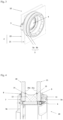
- a door assembly 1 is described, equipping an enclosure comprising a glass wall 2 provided with at least one passage opening for the passage of products from outside the enclosure to inside it and vice versa.
- the door assembly 1 is arranged to constitute a junction device for connecting a closed volume, such as a container, bag or the like, equipped with a door assembly cooperating with the door assembly 1 according to the invention, without breaking the confinement.
- the door assembly 1 comprises a flange 3 intended to be fixed on the wall portion 20 delimiting the passage opening on the one hand and an opening 4 mounted to move relative to the flange 3 between a closed position in which the opening 4 closes the passage opening and an open position.
- the opening 4 is mounted to move on the flange 3 by a hinge 5.
- the flange 3 of the door assembly 1 comprises two flange elements 3a, 3b distinct from each other and assembled to each other by means, in the example illustrated, of assembly screws 6.
- the assembly screws 6 are masked by covers 12.
- the flange elements 3a, 3b are assembled directly to each other.
- the flange 3 is mounted on the wall portion 20 of the enclosure, one of the flange elements 3a being located inside the enclosure while the other flange element 3b is located outside the enclosure.
- the flange elements 3a, 3b thus respectively define a crown inside the enclosure and a crown outside the enclosure.
- the inner and outer crowns are designated hereinafter with the same references as those of the flange elements 3a, 3b.
- the rings 3a, 3b have a surface 30a, 30b arranged to bear directly or indirectly on the surface of the wall portion 20 opposite which it is placed.
- the inner ring 3a has an external bearing surface 30a bearing directly on the internal surface 20a of the wall portion 20 while the outer ring 3b has an internal bearing surface 30b bearing on the external surface 20b of the wall portion 20.
- the bearing is provided by pressure screws 11 housed in holes made in the outer ring 3b and projecting from the internal bearing surface 30b.
- two protective washers 7, 9, advantageously made of plastic, are interposed respectively between the inner ring 3a and the wall portion 20 on the one hand and between the outer ring 3b and the wall portion 20 on the other hand.
- These protective washers are subsequently referred to as inner 7 and outer 9 protective washers.
- the inner protective washer 7, of annular shape is housed in a groove delimited by the peripheral rim 31a of the inner ring and a circular collar 33a outside the inner ring 3a.
- the outer washer 9 for its part comprises an annular body whose periphery outer is provided with a heel 90 extending along the outer periphery 32b of the outer crown 3b on the one hand and along the wall portion 20.
- the door assembly 1 comprises at least one annular seal, advantageously elastomer, and preferably silicone, inserted between the wall portion 20 and the bearing surface of at least one of the two rings 3a, 3b.
- the door assembly 1 comprises a single seal 8 inserted between the peripheral rim 31a of the inner ring 3a and the wall portion 20 of the enclosure. More particularly, the seal 8 is located in the gap delimited by the peripheral rim 31a of the inner crown 3a, the inner protective washer 7 and the inner surface 20a of the wall portion 20. It also has a heel 80 extending along the outer periphery 32a of the inner crown 3a on the one hand and along the inner surface 20a of the wall portion 20.
- the crushing of the seal 8 is carried out using the pressure screws 11.
- the pressure screws 11 mounted through the outer ring 3b and extending beyond the inner bearing surface of the outer ring 3b thus press the outer protective washer 9 against the wall portion 20, pressing the latter against the inner protective washer 7 while simultaneously crushing the seal 8.
- the assembly of the crowns 3a, 3b is carried out by assembly means, in the example screws, without the latter passing through the wall.
- the screw-receiving holes are thus provided on the crowns 3a, 3b to be radially offset from the edge of the wall portion 20 when the crowns 3a and 3b are mounted on the wall 2.
- the assembly screws 6 pass through the crowns 3a and 3b near the edge of the wall portion 20, the screw holes provided in the inner crown being located in the circular collar 33a.
- FIGS. 3 and 4 illustrate another example of mounting a door assembly 10 according to the invention.
- the door assembly 10 is mounted on an enclosure wall formed of two wall elements 20, 21.
- This door assembly 10 incorporates all of the elements previously described except that the outer ring 3b and the outer protective washer 9 come to bear on the wall portion 21a of the outer wall element 21 while the inner ring 3a, the washer internal protection 7 and the sealing gasket 8 come to bear against the wall portion 20a of the internal wall element 20.
- the door assembly 10 further comprises a spacer 13 placed between the two wall elements 20, 21.
- the spacer 13 is assembled with the flange elements 3a, 3b by means of the assembly screws 6, the latter passing right through the spacer 13 to connect the two flange elements 3a, 3b, without passing through the wall elements 20, 21.
- Two annular seals 14, 15, of substantially circular section, are placed between the spacer 13 and each of the wall portions 20a, 21a of the wall elements 20, 21.
- the seal between the two wall elements 20, 21 is ensured by crushing said seals 14, 15 via the pressure screws.
- door assemblies are described in connection with a single or double glass wall. It is of course obvious that the door assembly according to the invention is not limited to this type of enclosure, and that it can be intended for enclosures having walls made of a material other than glass without departing from the scope of the invention.
Landscapes
- Engineering & Computer Science (AREA)
- Mechanical Engineering (AREA)
- General Engineering & Computer Science (AREA)
- High Energy & Nuclear Physics (AREA)
- Physics & Mathematics (AREA)
- Chemical & Material Sciences (AREA)
- Health & Medical Sciences (AREA)
- Clinical Laboratory Science (AREA)
- Robotics (AREA)
- Chemical Kinetics & Catalysis (AREA)
- Pressure Vessels And Lids Thereof (AREA)
- Securing Of Glass Panes Or The Like (AREA)
- Civil Engineering (AREA)
- Structural Engineering (AREA)
- Manipulator (AREA)
- Casings For Electric Apparatus (AREA)
- Closures For Containers (AREA)
- Lock And Its Accessories (AREA)
Applications Claiming Priority (2)
| Application Number | Priority Date | Filing Date | Title |
|---|---|---|---|
| FR1914959A FR3105054B1 (fr) | 2019-12-19 | 2019-12-19 | Ensemble formant porte permettant un montage ameliore sur les paroi d’une enceinte, et enceinte comportant un tel ensemble de porte |
| PCT/FR2020/052503 WO2021123641A1 (fr) | 2019-12-19 | 2020-12-17 | Ensemble formant porte permettant un montage ameliore sur les parois d'une enceinte, et enceinte comportant un tel ensemble de porte |
Publications (3)
| Publication Number | Publication Date |
|---|---|
| EP4076872A1 EP4076872A1 (fr) | 2022-10-26 |
| EP4076872C0 EP4076872C0 (fr) | 2025-05-07 |
| EP4076872B1 true EP4076872B1 (fr) | 2025-05-07 |
Family
ID=70738628
Family Applications (1)
| Application Number | Title | Priority Date | Filing Date |
|---|---|---|---|
| EP20845600.4A Active EP4076872B1 (fr) | 2019-12-19 | 2020-12-17 | Ensemble formant porte permettant un montage ameliore sur les parois d'une enceinte, et enceinte comportant un tel ensemble de porte |
Country Status (6)
| Country | Link |
|---|---|
| US (1) | US20230015340A1 (https=) |
| EP (1) | EP4076872B1 (https=) |
| JP (2) | JP2023507131A (https=) |
| CN (1) | CN115151392A (https=) |
| FR (1) | FR3105054B1 (https=) |
| WO (1) | WO2021123641A1 (https=) |
Families Citing this family (2)
| Publication number | Priority date | Publication date | Assignee | Title |
|---|---|---|---|---|
| JP7381109B2 (ja) * | 2021-10-27 | 2023-11-15 | 万善工機株式会社 | 物品連結構造 |
| JP1723868S (ja) * | 2021-12-23 | 2022-09-02 | 移送ドア |
Citations (1)
| Publication number | Priority date | Publication date | Assignee | Title |
|---|---|---|---|---|
| EP3466618A1 (en) * | 2016-05-23 | 2019-04-10 | Nara Machinery Co., Ltd. | Port structure of containment apparatus, port forming kit for containment apparatus, and containment apparatus |
Family Cites Families (20)
| Publication number | Priority date | Publication date | Assignee | Title |
|---|---|---|---|---|
| US4010588A (en) * | 1973-10-19 | 1977-03-08 | Central Research Laboratories, Inc. | Sealing device |
| US4141609A (en) * | 1977-11-25 | 1979-02-27 | Central Research Laboratories, Inc. | System for effecting access into sealed enclosures |
| FR2496325B1 (fr) * | 1980-12-16 | 1987-05-22 | Calhene | Dispositif de securite pour systeme de verrouillage entre deux enceintes etanches |
| US4480426A (en) * | 1982-01-19 | 1984-11-06 | The United States Of America As Represented By The United States Department Of Energy | Material bagging device |
| FR2652143B1 (fr) * | 1989-09-15 | 1991-12-13 | Euritech | Dispositif de fixation etanche d'un organe interchangeable dans une bride de cellule et outil de montage d'un tel dispositif. |
| FR2695343B1 (fr) * | 1992-09-04 | 1994-11-25 | Sne Calhene | Mécanisme de commande centralisé, à sécurités incorporées, pour un dispositif de transfert étanche entre deux volumes clos. |
| US5460439A (en) * | 1994-01-07 | 1995-10-24 | Delaware Capital Formation, Inc. | Sealed transfer system |
| US5662581A (en) * | 1995-01-05 | 1997-09-02 | Delaware Capital Formation, Inc. | Easily sterilizable glove system |
| FR2777822B1 (fr) | 1998-04-23 | 2000-07-07 | Calhene | Dispositif de transfert etanche a decontamination integree, par rayonnements ultraviolets |
| JP2000343479A (ja) * | 1999-06-08 | 2000-12-12 | Earekkusu:Kk | アイソレータ装置のグローブ機構 |
| FR2834582B1 (fr) * | 2002-01-09 | 2004-04-02 | Calhene | Procede de montage d'un equipement de manipulation sur une enceinte de confinement contenant un milieu sterile |
| US7257927B2 (en) * | 2003-08-15 | 2007-08-21 | Premier Technology, Inc. | Three-piece frame assembly for window of enclosure |
| US7780248B2 (en) * | 2005-07-19 | 2010-08-24 | Merrick & Company | Glovebox for a double wall containment module |
| FR2944380B1 (fr) * | 2009-04-09 | 2011-05-13 | Charles Glachet | Dispositif de fixation etanche d'un organe interchangeable dans une bague d'enceinte montee sur une paroi de cellule de confinement |
| US8887365B2 (en) * | 2009-09-24 | 2014-11-18 | Delaware Capital Formation, Inc. | Glove port retrofit assembly and method of replacing components |
| US10538001B2 (en) * | 2011-03-16 | 2020-01-21 | Intech Defense, Llc | Methods and systems for providing protection against harmful materials |
| FR3010120B1 (fr) * | 2013-09-03 | 2016-03-04 | Getinge La Calhene | Dispositif de connexion etanche entre deux volumes clos comportant des moyens de maintien prealablement a la connexion |
| FR3036054B1 (fr) | 2015-05-12 | 2017-06-09 | Charles Glachet | Bride et porte de conteneur en matiere plastique a compensation des tolerances d'injection pour connexion |
| US10550940B2 (en) * | 2016-07-11 | 2020-02-04 | In-Line Flow Products Ltd. | Closure for pressure vessel or pipeline |
| EP3621774A1 (en) * | 2017-05-08 | 2020-03-18 | Delaware Capital Formation, Inc. | Access port having a cover |
-
2019
- 2019-12-19 FR FR1914959A patent/FR3105054B1/fr active Active
-
2020
- 2020-12-17 JP JP2022536790A patent/JP2023507131A/ja active Pending
- 2020-12-17 EP EP20845600.4A patent/EP4076872B1/fr active Active
- 2020-12-17 US US17/787,195 patent/US20230015340A1/en active Pending
- 2020-12-17 WO PCT/FR2020/052503 patent/WO2021123641A1/fr not_active Ceased
- 2020-12-17 CN CN202080086481.6A patent/CN115151392A/zh active Pending
-
2025
- 2025-06-23 JP JP2025105648A patent/JP2025165923A/ja active Pending
Patent Citations (1)
| Publication number | Priority date | Publication date | Assignee | Title |
|---|---|---|---|---|
| EP3466618A1 (en) * | 2016-05-23 | 2019-04-10 | Nara Machinery Co., Ltd. | Port structure of containment apparatus, port forming kit for containment apparatus, and containment apparatus |
Also Published As
| Publication number | Publication date |
|---|---|
| WO2021123641A1 (fr) | 2021-06-24 |
| US20230015340A1 (en) | 2023-01-19 |
| FR3105054A1 (fr) | 2021-06-25 |
| EP4076872A1 (fr) | 2022-10-26 |
| CN115151392A (zh) | 2022-10-04 |
| JP2025165923A (ja) | 2025-11-05 |
| JP2023507131A (ja) | 2023-02-21 |
| EP4076872C0 (fr) | 2025-05-07 |
| FR3105054B1 (fr) | 2023-03-10 |
Similar Documents
| Publication | Publication Date | Title |
|---|---|---|
| EP4076747B1 (fr) | Conteneur etanche comprenant un dispositif permettant un raccordement amovible a une enceinte | |
| EP4076872B1 (fr) | Ensemble formant porte permettant un montage ameliore sur les parois d'une enceinte, et enceinte comportant un tel ensemble de porte | |
| EP4076753B1 (fr) | Conteneur à étanchéité renforcée | |
| FR2959496A1 (fr) | Boitier etanche a l'air | |
| FR3102698A1 (fr) | Conteneur etanche comprenant un dispositif permettant un raccordement amovible a une enceinte | |
| EP4076873A1 (fr) | Arrangement de porte permettant un transfert etanche entre deux volumes clos | |
| FR2956953A1 (fr) | Base de boitier, boitier et procede d'assemblage associes | |
| EP0247921B1 (fr) | Dispositif deconnectable pour la mise en communication de deux volumes clos sans rupture du confinement | |
| EP4055615A1 (fr) | Dispositif de jonction etanche entre deux enceintes de confinement offrant une etancheite amelioree | |
| FR3117464A1 (fr) | Ensemble de connexion pour conteneur de transfert etanche | |
| EP0312460A1 (fr) | Dipositif de raccordement déconnectable de deux enceintes étanches | |
| EP4076754B1 (fr) | Conteneur étanche pourvu d'une bride bi-matière | |
| EP4153506A1 (fr) | Conteneur etanche a paroi souple comprenant une bague de fixation pour son assemblage avec un dispositif permettant un raccordement amovible du conteneur a une enceinte | |
| EP0763876B1 (fr) | Dispositif de blocage d'un cable dans un boítier antidéflagrant | |
| EP4076874B1 (fr) | Arrangement de porte equipant un premier volume clos permettant de reduire les risques de contamination lors du raccordement d'un deuxieme volume clos au premier volume clos | |
| FR2994561A1 (fr) | Systeme de fixation par sertissage d'un couvercle sur une enceinte close | |
| WO2023111303A1 (fr) | Conteneur etanche comprenant une bande de renfort d'etancheite bicouche | |
| EP2609942A1 (fr) | Dispositif anti retour de fluides incorporé dans un ensemble d'expression de lait maternel | |
| FR3162998A1 (fr) | Conteneur etanche raccordable a une enceinte sterile comprenant une collerette de protection d’une potentielle contamination lors du transfert de produits | |
| FR3163199A1 (fr) | Conteneur blindé pour le transport d’un récipient contenant un produit radioactif | |
| FR3125318A1 (fr) | Interface de connexion tournante pour conteneur de transfert etanche | |
| FR2873611A1 (fr) | Dispositif pour assurer l'etancheite de gants dans des installations pharmaceutiques | |
| FR2465935A1 (fr) | Regard d'observation a lentille pour recipient sous pression de grandes dimensions |
Legal Events
| Date | Code | Title | Description |
|---|---|---|---|
| STAA | Information on the status of an ep patent application or granted ep patent |
Free format text: STATUS: UNKNOWN |
|
| STAA | Information on the status of an ep patent application or granted ep patent |
Free format text: STATUS: THE INTERNATIONAL PUBLICATION HAS BEEN MADE |
|
| PUAI | Public reference made under article 153(3) epc to a published international application that has entered the european phase |
Free format text: ORIGINAL CODE: 0009012 |
|
| STAA | Information on the status of an ep patent application or granted ep patent |
Free format text: STATUS: REQUEST FOR EXAMINATION WAS MADE |
|
| 17P | Request for examination filed |
Effective date: 20220530 |
|
| AK | Designated contracting states |
Kind code of ref document: A1 Designated state(s): AL AT BE BG CH CY CZ DE DK EE ES FI FR GB GR HR HU IE IS IT LI LT LU LV MC MK MT NL NO PL PT RO RS SE SI SK SM TR |
|
| DAV | Request for validation of the european patent (deleted) | ||
| DAX | Request for extension of the european patent (deleted) | ||
| STAA | Information on the status of an ep patent application or granted ep patent |
Free format text: STATUS: EXAMINATION IS IN PROGRESS |
|
| 17Q | First examination report despatched |
Effective date: 20240208 |
|
| RAP3 | Party data changed (applicant data changed or rights of an application transferred) |
Owner name: ABC TRANSFER |
|
| GRAP | Despatch of communication of intention to grant a patent |
Free format text: ORIGINAL CODE: EPIDOSNIGR1 |
|
| STAA | Information on the status of an ep patent application or granted ep patent |
Free format text: STATUS: GRANT OF PATENT IS INTENDED |
|
| INTG | Intention to grant announced |
Effective date: 20250127 |
|
| GRAS | Grant fee paid |
Free format text: ORIGINAL CODE: EPIDOSNIGR3 |
|
| GRAA | (expected) grant |
Free format text: ORIGINAL CODE: 0009210 |
|
| STAA | Information on the status of an ep patent application or granted ep patent |
Free format text: STATUS: THE PATENT HAS BEEN GRANTED |
|
| AK | Designated contracting states |
Kind code of ref document: B1 Designated state(s): AL AT BE BG CH CY CZ DE DK EE ES FI FR GB GR HR HU IE IS IT LI LT LU LV MC MK MT NL NO PL PT RO RS SE SI SK SM TR |
|
| REG | Reference to a national code |
Ref country code: GB Ref legal event code: FG4D Free format text: NOT ENGLISH |
|
| REG | Reference to a national code |
Ref country code: CH Ref legal event code: EP |
|
| REG | Reference to a national code |
Ref country code: DE Ref legal event code: R096 Ref document number: 602020051026 Country of ref document: DE |
|
| REG | Reference to a national code |
Ref country code: IE Ref legal event code: FG4D Free format text: LANGUAGE OF EP DOCUMENT: FRENCH |
|
| U01 | Request for unitary effect filed |
Effective date: 20250519 |
|
| U07 | Unitary effect registered |
Designated state(s): AT BE BG DE DK EE FI FR IT LT LU LV MT NL PT RO SE SI Effective date: 20250523 |
|
| PG25 | Lapsed in a contracting state [announced via postgrant information from national office to epo] |
Ref country code: ES Free format text: LAPSE BECAUSE OF FAILURE TO SUBMIT A TRANSLATION OF THE DESCRIPTION OR TO PAY THE FEE WITHIN THE PRESCRIBED TIME-LIMIT Effective date: 20250507 |
|
| PG25 | Lapsed in a contracting state [announced via postgrant information from national office to epo] |
Ref country code: GR Free format text: LAPSE BECAUSE OF FAILURE TO SUBMIT A TRANSLATION OF THE DESCRIPTION OR TO PAY THE FEE WITHIN THE PRESCRIBED TIME-LIMIT Effective date: 20250808 Ref country code: NO Free format text: LAPSE BECAUSE OF FAILURE TO SUBMIT A TRANSLATION OF THE DESCRIPTION OR TO PAY THE FEE WITHIN THE PRESCRIBED TIME-LIMIT Effective date: 20250807 |
|
| PG25 | Lapsed in a contracting state [announced via postgrant information from national office to epo] |
Ref country code: PL Free format text: LAPSE BECAUSE OF FAILURE TO SUBMIT A TRANSLATION OF THE DESCRIPTION OR TO PAY THE FEE WITHIN THE PRESCRIBED TIME-LIMIT Effective date: 20250507 |
|
| PG25 | Lapsed in a contracting state [announced via postgrant information from national office to epo] |
Ref country code: HR Free format text: LAPSE BECAUSE OF FAILURE TO SUBMIT A TRANSLATION OF THE DESCRIPTION OR TO PAY THE FEE WITHIN THE PRESCRIBED TIME-LIMIT Effective date: 20250507 |
|
| PG25 | Lapsed in a contracting state [announced via postgrant information from national office to epo] |
Ref country code: RS Free format text: LAPSE BECAUSE OF FAILURE TO SUBMIT A TRANSLATION OF THE DESCRIPTION OR TO PAY THE FEE WITHIN THE PRESCRIBED TIME-LIMIT Effective date: 20250807 |
|
| PG25 | Lapsed in a contracting state [announced via postgrant information from national office to epo] |
Ref country code: IS Free format text: LAPSE BECAUSE OF FAILURE TO SUBMIT A TRANSLATION OF THE DESCRIPTION OR TO PAY THE FEE WITHIN THE PRESCRIBED TIME-LIMIT Effective date: 20250907 |
|
| PGFP | Annual fee paid to national office [announced via postgrant information from national office to epo] |
Ref country code: GB Payment date: 20251219 Year of fee payment: 6 |
|
| PG25 | Lapsed in a contracting state [announced via postgrant information from national office to epo] |
Ref country code: SM Free format text: LAPSE BECAUSE OF FAILURE TO SUBMIT A TRANSLATION OF THE DESCRIPTION OR TO PAY THE FEE WITHIN THE PRESCRIBED TIME-LIMIT Effective date: 20250507 |
|
| PG25 | Lapsed in a contracting state [announced via postgrant information from national office to epo] |
Ref country code: CZ Free format text: LAPSE BECAUSE OF FAILURE TO SUBMIT A TRANSLATION OF THE DESCRIPTION OR TO PAY THE FEE WITHIN THE PRESCRIBED TIME-LIMIT Effective date: 20250507 |
|
| PG25 | Lapsed in a contracting state [announced via postgrant information from national office to epo] |
Ref country code: SK Free format text: LAPSE BECAUSE OF FAILURE TO SUBMIT A TRANSLATION OF THE DESCRIPTION OR TO PAY THE FEE WITHIN THE PRESCRIBED TIME-LIMIT Effective date: 20250507 |
|
| U20 | Renewal fee for the european patent with unitary effect paid |
Year of fee payment: 6 Effective date: 20251230 |
|
| PLBE | No opposition filed within time limit |
Free format text: ORIGINAL CODE: 0009261 |
|
| STAA | Information on the status of an ep patent application or granted ep patent |
Free format text: STATUS: NO OPPOSITION FILED WITHIN TIME LIMIT |
|
| REG | Reference to a national code |
Ref country code: CH Ref legal event code: L10 Free format text: ST27 STATUS EVENT CODE: U-0-0-L10-L00 (AS PROVIDED BY THE NATIONAL OFFICE) Effective date: 20260318 |
|
| 26N | No opposition filed |
Effective date: 20260210 |