EP4074609B1 - Füllstation für behälter im pharmazeutischen bereich und verfahren dafür - Google Patents
Füllstation für behälter im pharmazeutischen bereich und verfahren dafür Download PDFInfo
- Publication number
- EP4074609B1 EP4074609B1 EP22167404.7A EP22167404A EP4074609B1 EP 4074609 B1 EP4074609 B1 EP 4074609B1 EP 22167404 A EP22167404 A EP 22167404A EP 4074609 B1 EP4074609 B1 EP 4074609B1
- Authority
- EP
- European Patent Office
- Prior art keywords
- filling
- washing
- station
- collector
- configuration
- Prior art date
- Legal status (The legal status is an assumption and is not a legal conclusion. Google has not performed a legal analysis and makes no representation as to the accuracy of the status listed.)
- Active
Links
Images
Classifications
-
- B—PERFORMING OPERATIONS; TRANSPORTING
- B65—CONVEYING; PACKING; STORING; HANDLING THIN OR FILAMENTARY MATERIAL
- B65B—MACHINES, APPARATUS OR DEVICES FOR, OR METHODS OF, PACKAGING ARTICLES OR MATERIALS; UNPACKING
- B65B1/00—Packaging fluent solid material, e.g. powders, granular or loose fibrous material, loose masses of small articles, in individual containers or receptacles, e.g. bags, sacks, boxes, cartons, cans, or jars
- B65B1/04—Methods of, or means for, filling the material into the containers or receptacles
-
- B—PERFORMING OPERATIONS; TRANSPORTING
- B65—CONVEYING; PACKING; STORING; HANDLING THIN OR FILAMENTARY MATERIAL
- B65B—MACHINES, APPARATUS OR DEVICES FOR, OR METHODS OF, PACKAGING ARTICLES OR MATERIALS; UNPACKING
- B65B25/00—Packaging other articles presenting special problems
-
- B—PERFORMING OPERATIONS; TRANSPORTING
- B67—OPENING, CLOSING OR CLEANING BOTTLES, JARS OR SIMILAR CONTAINERS; LIQUID HANDLING
- B67C—CLEANING, FILLING WITH LIQUIDS OR SEMILIQUIDS, OR EMPTYING, OF BOTTLES, JARS, CANS, CASKS, BARRELS, OR SIMILAR CONTAINERS, NOT OTHERWISE PROVIDED FOR; FUNNELS
- B67C3/00—Bottling liquids or semiliquids; Filling jars or cans with liquids or semiliquids using bottling or like apparatus; Filling casks or barrels with liquids or semiliquids
- B67C3/001—Cleaning of filling devices
-
- B—PERFORMING OPERATIONS; TRANSPORTING
- B67—OPENING, CLOSING OR CLEANING BOTTLES, JARS OR SIMILAR CONTAINERS; LIQUID HANDLING
- B67C—CLEANING, FILLING WITH LIQUIDS OR SEMILIQUIDS, OR EMPTYING, OF BOTTLES, JARS, CANS, CASKS, BARRELS, OR SIMILAR CONTAINERS, NOT OTHERWISE PROVIDED FOR; FUNNELS
- B67C7/00—Concurrent cleaning, filling, and closing of bottles; Processes or devices for at least two of these operations
- B67C7/0006—Conveying; Synchronising
- B67C7/0026—Conveying; Synchronising the containers travelling along a linear path
- B67C7/0033—Conveying; Synchronising the containers travelling along a linear path the operation being performed batch-wise
Definitions
- the present invention relates to a filling station for containers of the pharmaceutical field and method thereof.
- a filling station for containers of the pharmaceutical field comprises a conveyor device that conveys the containers (for example vials or bottles) along a filling path, a filling head arranged along the path which comprises a plurality of dispensing nozzles arranged to dispense a filling material (for example liquid or powder) inside the containers.
- the head results in the respective filling configuration.
- Filling stations of the pharmaceutical field often provide for a dedicated automatic washing and/or sterilization system of the filling circuits on site (namely, the so-called CIP/SIP systems), allowing the latter to be cleaned without having to completely disassemble the filling system.
- the washing/sterilization cycle is necessary periodically or, in any case, between two filling cycles which involve two different products.
- the washing/sterilization can take place by means of chemical agents and/or steam at high temperatures which are passed through the circuit and then collected for disposal.
- the filling station is brought into a washing configuration: in detail, the dispensing nozzles are removed from the filling head and inserted into corresponding washing collectors (also called "false bottles") arranged adjacent to the conveyor.
- the nozzles are connected by means of pipes to the washing circuit for dispensing the washing fluid to the collectors through the respective opening.
- Patent application DE102019211885A1 describes a device for handling containers comprising: a support with at least a filling and/or closing element suitable for filling and/or closing a container, and at least an extension arm connected to the support
- Patent application GB2324999A describes an evacuation and sealing device comprising a module which is provided with a plurality of evacuation and sealing units and is independently movable along three mutually perpendicular axes; the module cooperates with a first conveyor device for small containers and a second conveyor device for container caps.
- the object of the present invention is to overcome said drawback. This object is achieved by means of a filling station and method according to the attached claims.
- the proposed filling station and method allow to reduce the time required for the preparation of the filling station, from the filling configuration to the washing one, and vice versa, with respect to the known art.
- the proposed filling station and method reduce machine downtime related to the cleaning cycles of the filling station compared to the prior art.
- the filling head is automatically movable from the respective filling configuration to a washing configuration (and vice versa), where the respective nozzle is arranged at the opening of the washing collector to fill the washing collector with the washing fluid through the opening of the collector.
- the manual intervention of the operator is therefore no longer necessary for carrying out the cleaning cycle.
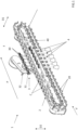
- the station 1 comprises: a conveyor 2 for conveying the containers C along a filling path P (the direction of which is indicated in Figures 1 , 2 and 4 ) and a filling head 3 comprising in turn at least a dispensing nozzle 30 (preferably more than one, as in the illustrated case).
- the filling head 3 can assume the filling configuration F (see Figure 1 ) in which the dispensing nozzle 30 is ready for filling the containers C conveyed by the conveyor 2 with a product (for example liquid or powder, not shown).
- a product for example liquid or powder, not shown.
- the filling station 1 further comprises at least a washing collector 4 (preferably more than one, as in the illustrated case), arranged adjacent to the filling path P and comprising an opening 40 (indicated in Figures 1-3 ) for receiving a washing fluid.
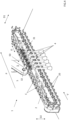
- the dispensing nozzle 30 can be coupled with the opening 40 (preferably insertable in the opening 40, as shown in Figure 4 ) of the washing collector 4 for dispensing a washing fluid in the washing collector 4 through the opening 40.
- the washing fluid can comprise chemical agents and/or steam at high temperatures (e.g., 120°C).
- the number of washing collectors 4 corresponds to the number of dispensing nozzles 30.
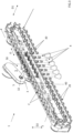
- the filling head 3 is automatically movable from the filling configuration F ( Figure 1 ) to a washing configuration S ( Figures 3 and 4 ), where the respective dispensing nozzle 30 is at the opening 40 of the washing collector 4 (preferably in the washing collector 4) to fill the washing collector 4 with the washing fluid through the opening 40, and vice versa.
- the proposed filling station 1 allows to reduce the machine downtime which, in the known art, was necessary to allow the operator to manually disconnect the dispensing nozzle from the filling head and place it in the washing collector, to which it was necessarily connected by piping and fixed for dispensing the washing fluid into the collector. Therefore, the productivity of the filling station 1 is significantly increased compared to the known art.
- the movement of the filling head 3 from the filling configuration F to the washing configuration S (and vice versa) takes place along a first direction D1, transversal to the filling path P.
- a first direction D1 transversal to the filling path P.
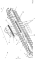
- the filling head 3 is further movable along a second direction D2, transversal to the filling path P, between a lowered position in which the dispensing nozzle 30 is inserted in the washing collector 4 and a raised position in which the dispensing nozzle 30 is not inserted in the washing collector 4 (see Figures 3 and 4 ).
- This movement of the filling head 3 along the second direction D2 also allows the dispensing nozzle 30 to enter the container C to be filled (lowered position), and to exit therefrom (raised position, see the Figures 1 and 2 ).
- the insertion and removal of the dispensing nozzle 30 in the washing collector 4 exploits a movement already possible for the filling head 3, without creating structural and functional complications.
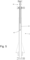
- the station 1 comprises a support arm 5, and the filling head 3 further comprises: a dispensing portion 31 (substantially parallel to the conveyor 2), which carries the dispensing nozzle 30, and an advancing portion 32 (substantially transversal and preferably perpendicular to the conveyor 2) which is connected to the dispensing portion 31 and bound to the support arm 5.
- the advancing portion 32 is movable with respect to the support arm 5 to bring the filling head 3 from the filling configuration F to the washing configuration S, and vice versa.
- the advancing portion 32 has a substantially cylindrical shape. According to an example, the advancing portion 32 is slidable with respect to the support arm 5
- the advancing portion 32 is telescopic, namely, it comprises a plurality of tubular portions sliding relative to one another to determine the movement of the filling head 3 from the filling configuration F to the washing configuration S, and vice versa.
- this specification guarantees a high structural simplicity of the filling head 3.
- the movement of the advancing portion 32 with respect to the support arm 5 is motorized.
- the support arm 5 is movable at least along a rotation direction O which is transversal to the first direction D1 of movement of the filling head 3 (namely, it is at least partially parallel to the filling path P of the containers C and to the conveyor 2 in the case illustrated).
- the support arm 5 is movable along said rotation direction O to move the filling head 3 along said second direction D2 (namely, from the respective lowered to the raised position, and vice versa).
- the station 1 comprises a base 50 arranged adjacent to the conveyor 2 and with respect to which the support arm 5 is bound (preferably hinged).
- the support arm 5 is movable with respect to the base 50 along said rotation direction O.
- the conveyor 2 has a linear development direction V (namely, it is a linear conveyor 2, for example with a closed loop comprising pockets 20), preferably parallel to the filling path P, and the filling head 3 comprises a plurality of dispensing nozzles 30 arranged in a row.
- the filling station 1 comprises a plurality of washing collectors 4 arranged in a row (with the number of dispensing nozzles 30 preferably coinciding with the number of washing collectors 4).
- the row of dispensing nozzles 30, the row of washing collectors 4 and the development direction V of the conveyor 2 are parallel to one another. This embodiment guarantees the system an optimal effectiveness and at the same time a high compactness (namely, it results in contained overall dimensions of the filling station 1).
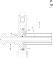
- each dispensing nozzle 30 of the filling head 3 is arranged inside the corresponding washing collector 4 passing through the opening 40; namely, in the washing configuration S each dispensing nozzle 30 of the filling head 3 is inserted into the corresponding washing collector 4 engaging the opening 40. Furthermore, in the washing configuration S each dispensing nozzle 30 of the filling head 3 seals the opening 40 of the washing collector 4 to prevent the overflow of the washing fluid from the opening 40; in this regard, each dispensing nozzle 30 of the filling head 3 or each washing collector 4 has an elastically deformable annular seal 41 which ensures the hydraulic seal between the dispensing nozzle 30 and the opening 40 of the washing collector 4.
- Each washing collector 4 has a cup-like shape which is delimited at the bottom by a bottom wall 42 (completely devoid of holes) opposite the opening 40 and is laterally delimited by a side wall 43 which is configured to contain, with a given clearance, the dispensing nozzle 30 of the filling head 3 arranged in the washing configuration S (namely, between the dispensing nozzle 30 of the filling head 3 and the side wall 43 of the washing collector 4 free space is provided).
- the side wall 43 of the washing collector 4 has at least a drain hole 44 (in effect a plurality of uniformly distributed drain holes) which is arranged on the opposite side of the bottom wall 42 near the opening 40 and is designed to allow the outflow of the washing fluid once the washing fluid has filled the washing collector 4.
- each dispensing nozzle 30 of the filling head 3 enters, through the opening 40, into the corresponding washing collector 4, sealing the opening 40 in a hermetic manner.
- the washing fluid is dispensed which, passing through the dispensing nozzle 30, cleans the inside of the said dispensing nozzle 30; when the washing fluid comes out of the dispensing nozzle 30 " hits " against the bottom wall 42 of the washing collector 4 and therefore, filling the washing collector 4, is forced to rise upwards until it reaches the drain hole 44 from which the washing fluid flows towards a drain.
- the washing fluid rises from bottom to top to reach the drain hole 44, it externally cleans the dispensing nozzle 30 as it flows over the outer surface of the dispensing nozzle 30.
- each washing collector 4 is "filled” by the washing fluid allows the corresponding dispensing nozzle 30 to be cleaned not only internally but also externally.
- the present invention further relates to a method for filling containers C of the pharmaceutical field (for example bottles or vials), which can be implemented by means of a filling station 1 of the type described above.
- containers C of the pharmaceutical field for example bottles or vials
- the method comprises the steps of:
- the method comprises the step of: automatically bringing the filling head 3 into the corresponding washing configuration S and filling the washing collector 4 with the washing fluid by means of the dispensing nozzle 30.
- the method comprises the step of automatically returning the filling head 3 to the corresponding filling configuration F.
- the method described above essentially comprises a filling and subsequent cleaning cycle that can be performed for example by means of the filling station 1, which is also the subject of the invention and described above.
- the method according to the invention therefore has the same advantages identified with reference to the filling station 1.
- the proposed method allows to reduce the downtimes that were necessary in the known art by increasing the productivity of the filling station 1 by which it is implemented.
Landscapes
- Engineering & Computer Science (AREA)
- Mechanical Engineering (AREA)
- Filling Of Jars Or Cans And Processes For Cleaning And Sealing Jars (AREA)
- Supplying Of Containers To The Packaging Station (AREA)
- Basic Packing Technique (AREA)
Claims (13)
- Abfüllstation (1) für Behälter (C) des pharmazeutischen Bereichs, umfassend:- einen Förderer (2) zum Befördern von Behältern (C) entlang eines Füllweges (P);- einen Abfüllkopf (3), der mindestens eine Abgabedüse (30) umfasst;
wobei der Abfüllkopf (3) eine Abfüllkonfiguration (F) annehmen kann, in der die Abgabedüse (30) bereit ist zum Befüllen der Behälter (C), die von dem Förderer (2) befördert werden, mit einem Produkt; und- einen Waschsammler (4), der neben dem Füllweg (P) angeordnet ist und eine Öffnung (40) zum Aufnehmen eines Waschfluids umfasst; wobei die Abgabedüse (30) mit der Öffnung (40) des Sammlers gekoppelt werden kann, um ein Waschfluid durch die Öffnung (40) in den Waschsammler (4) abzugeben;dadurch gekennzeichnet, dass der Abfüllkopf (3) von der Abfüllkonfiguration (F) in eine Waschkonfiguration (S), in der sich die jeweilige Abgabedüse (30) an der Öffnung (40) des Waschsammlers (4) befindet, um den Waschsammler (4) durch die Öffnung (40) mit dem Waschfluid zu füllen, und umgekehrt, automatisch bewegbar ist. - Station (1) nach Anspruch 1, wobei in der Waschkonfiguration (S) die Abgabedüse (30) des Abfüllkopfs (3) innerhalb des Waschsammlers (4) angeordnet ist und durch die Öffnung (40) verläuft.
- Station (1) nach Anspruch 2, wobei in der Waschkonfiguration (S) die Abgabedüse (30) des Abfüllkopfs (3) die Öffnung (40) des Waschsammlers (4) abdichtet, um zu verhindern, dass das Waschfluid aus der Öffnung (40) überläuft.
- Station (1) nach Anspruch 3, wobei:der Waschsammler (4) eine becherartige Form aufweist, die am Boden durch eine Bodenwand (42) ohne Löcher und der Öffnung (40) gegenüberliegend begrenzt ist und durch eine Seitenwand (43) seitlich begrenzt ist, und der konfiguriert ist, in einem gegebenem Abstand die Abgabedüse (30) des Abfüllkopfs (3), der in der Waschkonfiguration (S) angeordnet ist, zu enthalten; unddie Seitenwand (43) des Waschsammlers (4) mindestens ein Ablaufloch (44) aufweist, das auf der gegenüberliegenden Seite der Bodenwand (42) nahe der Öffnung (40) angeordnet ist und ausgelegt ist, das Ablaufen des Waschfluids zu erlauben, sobald das Waschfluid den Waschsammler (4) gefüllt hat.
- Station (1) nach einem der vorhergehenden Ansprüche, wobei die Bewegung des Abfüllkopfes (3) von der Abfüllkonfiguration (F) in die Waschkonfiguration (S), und umgekehrt, entlang einer ersten Richtung (D1) horizontal und transversal zu dem Füllweg (P) stattfindet.
- Station (1) nach einem der vorhergehenden Ansprüche, wobei der Abfüllkopf (3) entlang einer zweiten Richtung (D2) vertikal und transversal zu dem Füllweg (P) zwischen einer abgesenkten Position, in der die Abgabedüse (30) in den Waschsammler (4) eingesetzt ist, und einer angehobenen Position, in der die Abgabedüse (30) nicht in den Waschsammler (4) eingesetzt ist, bewegbar ist.
- Station (1) nach einem der vorhergehenden Ansprüche, ferner umfassend:
einen Tragarm (5); wobei der Abfüllkopf (3) umfasst: einen Abgabeabschnitt (31), der die Abgabedüse (30) trägt, und einen Vorschubabschnitt (32), der mit dem Abgabeabschnitt (31) verbunden ist und an den Tragarm (5) gebunden ist; wobei der Vorschubabschnitt (32) bezüglich des Tragarms (5) bewegbar ist, um den Abfüllkopf (3) von der Abfüllkonfiguration (F) in die Waschkonfiguration (S) zu bringen, und umgekehrt. - Station (1) nach Anspruch 7, wobei der Vorschubabschnitt (32) teleskopisch ist.
- Station (1) nach Anspruch 7 oder 8, wobei der Vorschubabschnitt (32) bezüglich des Tragarms (5) verschiebbar ist.
- Station (1) nach Anspruch 7, 8 oder 9, wobei der Tragarm (5) entlang einer Drehrichtung (O), die zumindest teilweise transversal zu der ersten Richtung (D1) der Bewegung des Abfüllkopfs (3) ist, bewegbar ist.
- Station (1) nach Anspruch 10, wobei:der Abfüllkopf (3) entlang einer zweiten Richtung (D2) transversal zu dem Füllweg (P) zwischen einer abgesenkten Position, in der die Abgabedüse (30) in den Waschsammler (4) eingesetzt ist, und einer angehobenen Position, in der die Abgabedüse (30) nicht in den Waschsammler (4) eingesetzt ist, vertikal bewegbar ist, undder Tragarm (5) entlang der Drehrichtung (O) bewegbar ist, um den Abfüllkopf (3) entlang der zweiten Richtung (D2) zu bewegen.
- Station (1) nach einem der vorhergehenden Ansprüche, wobei:der Förderer (2) eine lineare Entwicklungsrichtung (V) aufweist;der Abfüllkopf (3) mehrere Abgabedüsen (30) umfasst, die in einer Reihe angeordnet sind;die Station (1) mehrere Waschsammler (4) umfasst, die in einer Reihe angeordnet sind; unddie Reihe der Abgabedüsen (30), die Reihe der Waschsammler (4) und die Entwicklungsrichtung (V) des Förderers (2) parallel zueinander sind.
- Füllverfahren zum Befüllen von Behältern des pharmazeutischen Bereichs, das mit der Abfüllstation (1) nach einem der vorhergehenden Ansprüche ausgeführt wird, und umfassend die Schritte:- Befördern mindestens eines Behälters (C) entlang des Füllweges (P); und- Bringen des Abfüllkopfs (3) in die jeweilige Abfüllkonfiguration (F) und Befüllen des Behälters (C) mittels der Abgabedüse (30);dadurch gekennzeichnet, dass es anschließend, den Schritt umfasst:automatisches Bringen des Abfüllkopfs (3) in die jeweilige Waschkonfiguration (S) und Befüllen des Waschsammlers (4) mit dem Waschfluid mittels der Abgabedüse (30); und anschließend, den Schritt umfasst:
automatisches Bringen des Abfüllkopfs (3) in die jeweilige Füllkonfiguration (F).
Applications Claiming Priority (1)
| Application Number | Priority Date | Filing Date | Title |
|---|---|---|---|
| IT102021000009086A IT202100009086A1 (it) | 2021-04-12 | 2021-04-12 | Stazione e metodo di riempimento per contenitori del settore farmaceutico |
Publications (2)
| Publication Number | Publication Date |
|---|---|
| EP4074609A1 EP4074609A1 (de) | 2022-10-19 |
| EP4074609B1 true EP4074609B1 (de) | 2025-02-19 |
Family
ID=77021806
Family Applications (1)
| Application Number | Title | Priority Date | Filing Date |
|---|---|---|---|
| EP22167404.7A Active EP4074609B1 (de) | 2021-04-12 | 2022-04-08 | Füllstation für behälter im pharmazeutischen bereich und verfahren dafür |
Country Status (3)
| Country | Link |
|---|---|
| EP (1) | EP4074609B1 (de) |
| ES (1) | ES3014134T3 (de) |
| IT (1) | IT202100009086A1 (de) |
Families Citing this family (1)
| Publication number | Priority date | Publication date | Assignee | Title |
|---|---|---|---|---|
| CN117735463A (zh) * | 2023-12-20 | 2024-03-22 | 浙江品控科技管理有限公司 | 一种自清洁的成分检测灌装机 |
Family Cites Families (6)
| Publication number | Priority date | Publication date | Assignee | Title |
|---|---|---|---|---|
| US4417610A (en) * | 1981-03-31 | 1983-11-29 | O.G. Hoyer A/S | Dispenser systems |
| GB8624595D0 (en) * | 1986-10-14 | 1986-11-19 | Metal Box Plc | Filling packaging containers |
| DE19716846C1 (de) * | 1997-04-22 | 1998-11-19 | Bosch Gmbh Robert | Evakuier- und Verschließvorrichtung |
| US20050028886A1 (en) * | 2003-08-05 | 2005-02-10 | Navarro Ramon M. | In line filling machine |
| US7011117B1 (en) * | 2004-11-15 | 2006-03-14 | Gerald Albert Carpino | Filling valve |
| DE102019211885A1 (de) * | 2019-08-08 | 2021-02-11 | Syntegon Technology Gmbh | Vorrichtung und Verfahren zum Handhaben von Behältern |
-
2021
- 2021-04-12 IT IT102021000009086A patent/IT202100009086A1/it unknown
-
2022
- 2022-04-08 EP EP22167404.7A patent/EP4074609B1/de active Active
- 2022-04-08 ES ES22167404T patent/ES3014134T3/es active Active
Also Published As
| Publication number | Publication date |
|---|---|
| ES3014134T3 (en) | 2025-04-16 |
| EP4074609A1 (de) | 2022-10-19 |
| IT202100009086A1 (it) | 2022-10-12 |
Similar Documents
| Publication | Publication Date | Title |
|---|---|---|
| JP3255923B2 (ja) | 滅菌バイアル充填装置 | |
| KR101780859B1 (ko) | 액상 내용물 주입 포장장치 | |
| US7980046B2 (en) | Apparatus for cleaning, filling, and capping a container | |
| EP4074609B1 (de) | Füllstation für behälter im pharmazeutischen bereich und verfahren dafür | |
| US4730435A (en) | Sterile docking system for filling IV bags | |
| EP2233412B1 (de) | Aufbewahrungssystem für Behälterartikel wie etwa Flaschen oder Spritzen, und dessen Anwendung | |
| EP4215463B1 (de) | Automatisiertes system zur handhabung, insbesondere zum umkippen, von behältern wie schalen von käfigen zur unterbringung von labortieren | |
| KR102024848B1 (ko) | 스파우트 파우치 포장장치 | |
| US10858205B2 (en) | Automated container-emptying device equipped with means for collecting and gravity-emptying containers and comprising a product collection zone | |
| EP3756775B1 (de) | Flaschenwaschmaschine | |
| JPH10338296A (ja) | 液体充填機の充填ノズルの洗浄装置 | |
| EP1838465B1 (de) | Einheit zum waschen von containern | |
| EP0103484A2 (de) | Füllmaschine für schäumende Flüssigkeiten | |
| EP0099605B1 (de) | Verpackungsmaschine | |
| EP3166882B1 (de) | Füllsystem zum füllen von flaschen oder dergleichen behältern | |
| CN206599432U (zh) | 直线式多工位液体无菌分装设备 | |
| KR101729240B1 (ko) | 파우치 포장기의 유체 주입 노즐 장치 | |
| JP2004323110A (ja) | 容器を充填するための装置 | |
| CN119551622A (zh) | 一种具有灌针防滴漏机构的bfs无菌灌装机装置 | |
| JP2853715B2 (ja) | 無菌充填装置 | |
| KR20250069595A (ko) | 멸균 폐쇄 환경에서 동작하고 폐쇄 환경의 내부에서 처리되어야 하는 제품들과의 접촉을 위해 사용되는 기계의 구성요소를 멸균하기 위한 방법 | |
| CN120943195A (zh) | 一种全自动水乳膏灌装旋盖一体机 | |
| JPH049290Y2 (de) | ||
| CN117623204A (zh) | 一种检测灌装机自动输送结构 | |
| DE1511536C (de) | Verpackungsmaschine fur Flaschen und ähnliche Behalter |
Legal Events
| Date | Code | Title | Description |
|---|---|---|---|
| PUAI | Public reference made under article 153(3) epc to a published international application that has entered the european phase |
Free format text: ORIGINAL CODE: 0009012 |
|
| STAA | Information on the status of an ep patent application or granted ep patent |
Free format text: STATUS: THE APPLICATION HAS BEEN PUBLISHED |
|
| AK | Designated contracting states |
Kind code of ref document: A1 Designated state(s): AL AT BE BG CH CY CZ DE DK EE ES FI FR GB GR HR HU IE IS IT LI LT LU LV MC MK MT NL NO PL PT RO RS SE SI SK SM TR |
|
| STAA | Information on the status of an ep patent application or granted ep patent |
Free format text: STATUS: REQUEST FOR EXAMINATION WAS MADE |
|
| 17P | Request for examination filed |
Effective date: 20230209 |
|
| RBV | Designated contracting states (corrected) |
Designated state(s): AL AT BE BG CH CY CZ DE DK EE ES FI FR GB GR HR HU IE IS IT LI LT LU LV MC MK MT NL NO PL PT RO RS SE SI SK SM TR |
|
| P01 | Opt-out of the competence of the unified patent court (upc) registered |
Effective date: 20230529 |
|
| GRAP | Despatch of communication of intention to grant a patent |
Free format text: ORIGINAL CODE: EPIDOSNIGR1 |
|
| STAA | Information on the status of an ep patent application or granted ep patent |
Free format text: STATUS: GRANT OF PATENT IS INTENDED |
|
| RIC1 | Information provided on ipc code assigned before grant |
Ipc: B67C 3/00 20060101ALI20240902BHEP Ipc: B65B 25/00 20060101ALI20240902BHEP Ipc: B65B 1/04 20060101AFI20240902BHEP |
|
| INTG | Intention to grant announced |
Effective date: 20240926 |
|
| GRAS | Grant fee paid |
Free format text: ORIGINAL CODE: EPIDOSNIGR3 |
|
| GRAA | (expected) grant |
Free format text: ORIGINAL CODE: 0009210 |
|
| STAA | Information on the status of an ep patent application or granted ep patent |
Free format text: STATUS: THE PATENT HAS BEEN GRANTED |
|
| AK | Designated contracting states |
Kind code of ref document: B1 Designated state(s): AL AT BE BG CH CY CZ DE DK EE ES FI FR GB GR HR HU IE IS IT LI LT LU LV MC MK MT NL NO PL PT RO RS SE SI SK SM TR |
|
| REG | Reference to a national code |
Ref country code: GB Ref legal event code: FG4D |
|
| REG | Reference to a national code |
Ref country code: CH Ref legal event code: EP |
|
| REG | Reference to a national code |
Ref country code: IE Ref legal event code: FG4D |
|
| REG | Reference to a national code |
Ref country code: DE Ref legal event code: R096 Ref document number: 602022010676 Country of ref document: DE |
|
| REG | Reference to a national code |
Ref country code: ES Ref legal event code: FG2A Ref document number: 3014134 Country of ref document: ES Kind code of ref document: T3 Effective date: 20250416 |
|
| REG | Reference to a national code |
Ref country code: NL Ref legal event code: MP Effective date: 20250219 |
|
| PG25 | Lapsed in a contracting state [announced via postgrant information from national office to epo] |
Ref country code: RS Free format text: LAPSE BECAUSE OF FAILURE TO SUBMIT A TRANSLATION OF THE DESCRIPTION OR TO PAY THE FEE WITHIN THE PRESCRIBED TIME-LIMIT Effective date: 20250519 |
|
| PG25 | Lapsed in a contracting state [announced via postgrant information from national office to epo] |
Ref country code: FI Free format text: LAPSE BECAUSE OF FAILURE TO SUBMIT A TRANSLATION OF THE DESCRIPTION OR TO PAY THE FEE WITHIN THE PRESCRIBED TIME-LIMIT Effective date: 20250219 |
|
| PG25 | Lapsed in a contracting state [announced via postgrant information from national office to epo] |
Ref country code: PL Free format text: LAPSE BECAUSE OF FAILURE TO SUBMIT A TRANSLATION OF THE DESCRIPTION OR TO PAY THE FEE WITHIN THE PRESCRIBED TIME-LIMIT Effective date: 20250219 |
|
| PGFP | Annual fee paid to national office [announced via postgrant information from national office to epo] |
Ref country code: DE Payment date: 20250429 Year of fee payment: 4 |
|
| PGFP | Annual fee paid to national office [announced via postgrant information from national office to epo] |
Ref country code: ES Payment date: 20250513 Year of fee payment: 4 |
|
| REG | Reference to a national code |
Ref country code: LT Ref legal event code: MG9D |
|
| PG25 | Lapsed in a contracting state [announced via postgrant information from national office to epo] |
Ref country code: NO Free format text: LAPSE BECAUSE OF FAILURE TO SUBMIT A TRANSLATION OF THE DESCRIPTION OR TO PAY THE FEE WITHIN THE PRESCRIBED TIME-LIMIT Effective date: 20250519 Ref country code: IS Free format text: LAPSE BECAUSE OF FAILURE TO SUBMIT A TRANSLATION OF THE DESCRIPTION OR TO PAY THE FEE WITHIN THE PRESCRIBED TIME-LIMIT Effective date: 20250619 |
|
| PG25 | Lapsed in a contracting state [announced via postgrant information from national office to epo] |
Ref country code: NL Free format text: LAPSE BECAUSE OF FAILURE TO SUBMIT A TRANSLATION OF THE DESCRIPTION OR TO PAY THE FEE WITHIN THE PRESCRIBED TIME-LIMIT Effective date: 20250219 |
|
| PG25 | Lapsed in a contracting state [announced via postgrant information from national office to epo] |
Ref country code: HR Free format text: LAPSE BECAUSE OF FAILURE TO SUBMIT A TRANSLATION OF THE DESCRIPTION OR TO PAY THE FEE WITHIN THE PRESCRIBED TIME-LIMIT Effective date: 20250219 |
|
| PG25 | Lapsed in a contracting state [announced via postgrant information from national office to epo] |
Ref country code: LV Free format text: LAPSE BECAUSE OF FAILURE TO SUBMIT A TRANSLATION OF THE DESCRIPTION OR TO PAY THE FEE WITHIN THE PRESCRIBED TIME-LIMIT Effective date: 20250219 Ref country code: PT Free format text: LAPSE BECAUSE OF FAILURE TO SUBMIT A TRANSLATION OF THE DESCRIPTION OR TO PAY THE FEE WITHIN THE PRESCRIBED TIME-LIMIT Effective date: 20250620 |
|
| PG25 | Lapsed in a contracting state [announced via postgrant information from national office to epo] |
Ref country code: BG Free format text: LAPSE BECAUSE OF FAILURE TO SUBMIT A TRANSLATION OF THE DESCRIPTION OR TO PAY THE FEE WITHIN THE PRESCRIBED TIME-LIMIT Effective date: 20250219 Ref country code: GR Free format text: LAPSE BECAUSE OF FAILURE TO SUBMIT A TRANSLATION OF THE DESCRIPTION OR TO PAY THE FEE WITHIN THE PRESCRIBED TIME-LIMIT Effective date: 20250520 |
|
| REG | Reference to a national code |
Ref country code: AT Ref legal event code: MK05 Ref document number: 1768095 Country of ref document: AT Kind code of ref document: T Effective date: 20250219 |
|
| PG25 | Lapsed in a contracting state [announced via postgrant information from national office to epo] |
Ref country code: SE Free format text: LAPSE BECAUSE OF FAILURE TO SUBMIT A TRANSLATION OF THE DESCRIPTION OR TO PAY THE FEE WITHIN THE PRESCRIBED TIME-LIMIT Effective date: 20250219 |
|
| PG25 | Lapsed in a contracting state [announced via postgrant information from national office to epo] |
Ref country code: SM Free format text: LAPSE BECAUSE OF FAILURE TO SUBMIT A TRANSLATION OF THE DESCRIPTION OR TO PAY THE FEE WITHIN THE PRESCRIBED TIME-LIMIT Effective date: 20250219 |
|
| PG25 | Lapsed in a contracting state [announced via postgrant information from national office to epo] |
Ref country code: DK Free format text: LAPSE BECAUSE OF FAILURE TO SUBMIT A TRANSLATION OF THE DESCRIPTION OR TO PAY THE FEE WITHIN THE PRESCRIBED TIME-LIMIT Effective date: 20250219 |
|
| PG25 | Lapsed in a contracting state [announced via postgrant information from national office to epo] |
Ref country code: IT Free format text: LAPSE BECAUSE OF FAILURE TO SUBMIT A TRANSLATION OF THE DESCRIPTION OR TO PAY THE FEE WITHIN THE PRESCRIBED TIME-LIMIT Effective date: 20250219 |
|
| PG25 | Lapsed in a contracting state [announced via postgrant information from national office to epo] |
Ref country code: AT Free format text: LAPSE BECAUSE OF FAILURE TO SUBMIT A TRANSLATION OF THE DESCRIPTION OR TO PAY THE FEE WITHIN THE PRESCRIBED TIME-LIMIT Effective date: 20250219 |
|
| PG25 | Lapsed in a contracting state [announced via postgrant information from national office to epo] |
Ref country code: EE Free format text: LAPSE BECAUSE OF FAILURE TO SUBMIT A TRANSLATION OF THE DESCRIPTION OR TO PAY THE FEE WITHIN THE PRESCRIBED TIME-LIMIT Effective date: 20250219 Ref country code: CZ Free format text: LAPSE BECAUSE OF FAILURE TO SUBMIT A TRANSLATION OF THE DESCRIPTION OR TO PAY THE FEE WITHIN THE PRESCRIBED TIME-LIMIT Effective date: 20250219 |
|
| PG25 | Lapsed in a contracting state [announced via postgrant information from national office to epo] |
Ref country code: RO Free format text: LAPSE BECAUSE OF FAILURE TO SUBMIT A TRANSLATION OF THE DESCRIPTION OR TO PAY THE FEE WITHIN THE PRESCRIBED TIME-LIMIT Effective date: 20250219 |
|
| PG25 | Lapsed in a contracting state [announced via postgrant information from national office to epo] |
Ref country code: SK Free format text: LAPSE BECAUSE OF FAILURE TO SUBMIT A TRANSLATION OF THE DESCRIPTION OR TO PAY THE FEE WITHIN THE PRESCRIBED TIME-LIMIT Effective date: 20250219 |
|
| REG | Reference to a national code |
Ref country code: DE Ref legal event code: R026 Ref document number: 602022010676 Country of ref document: DE |
|
| PLBI | Opposition filed |
Free format text: ORIGINAL CODE: 0009260 |
|
| REG | Reference to a national code |
Ref country code: CH Ref legal event code: L10 Free format text: ST27 STATUS EVENT CODE: U-0-0-L10-L00 (AS PROVIDED BY THE NATIONAL OFFICE) Effective date: 20251119 |
|
| REG | Reference to a national code |
Ref country code: CH Ref legal event code: H13 Free format text: ST27 STATUS EVENT CODE: U-0-0-H10-H13 (AS PROVIDED BY THE NATIONAL OFFICE) Effective date: 20251125 |
|
| PLAX | Notice of opposition and request to file observation + time limit sent |
Free format text: ORIGINAL CODE: EPIDOSNOBS2 |
|
| PG25 | Lapsed in a contracting state [announced via postgrant information from national office to epo] |
Ref country code: LU Free format text: LAPSE BECAUSE OF NON-PAYMENT OF DUE FEES Effective date: 20250408 |
|
| 26 | Opposition filed |
Opponent name: FOCKE & CO. (GMBH & CO. KG) Effective date: 20251107 |