EP4074580A1 - Fahrzeugsteuerungssystem und fahrzeugsteuerungsverfahren - Google Patents
Fahrzeugsteuerungssystem und fahrzeugsteuerungsverfahren Download PDFInfo
- Publication number
- EP4074580A1 EP4074580A1 EP22165518.6A EP22165518A EP4074580A1 EP 4074580 A1 EP4074580 A1 EP 4074580A1 EP 22165518 A EP22165518 A EP 22165518A EP 4074580 A1 EP4074580 A1 EP 4074580A1
- Authority
- EP
- European Patent Office
- Prior art keywords
- control
- steering
- reaction force
- vehicle
- driving assist
- Prior art date
- Legal status (The legal status is an assumption and is not a legal conclusion. Google has not performed a legal analysis and makes no representation as to the accuracy of the status listed.)
- Granted
Links
- 238000000034 method Methods 0.000 title claims description 8
- 230000005540 biological transmission Effects 0.000 claims abstract description 63
- 230000009849 deactivation Effects 0.000 claims abstract description 59
- 230000010355 oscillation Effects 0.000 claims abstract description 14
- 238000010586 diagram Methods 0.000 description 39
- 230000001629 suppression Effects 0.000 description 18
- 238000004364 calculation method Methods 0.000 description 11
- 230000008859 change Effects 0.000 description 9
- 230000000694 effects Effects 0.000 description 9
- 230000009467 reduction Effects 0.000 description 8
- 230000006870 function Effects 0.000 description 5
- 230000004048 modification Effects 0.000 description 5
- 238000012986 modification Methods 0.000 description 5
- 230000004044 response Effects 0.000 description 5
- 230000001133 acceleration Effects 0.000 description 4
- 230000002452 interceptive effect Effects 0.000 description 3
- 230000006872 improvement Effects 0.000 description 2
- 239000003638 chemical reducing agent Substances 0.000 description 1
- 238000004590 computer program Methods 0.000 description 1
- 238000013016 damping Methods 0.000 description 1
- 230000007423 decrease Effects 0.000 description 1
- 238000001514 detection method Methods 0.000 description 1
- 239000000284 extract Substances 0.000 description 1
- 238000003384 imaging method Methods 0.000 description 1
- 230000007246 mechanism Effects 0.000 description 1
- 230000008569 process Effects 0.000 description 1
- 239000007787 solid Substances 0.000 description 1
Images


Classifications
-
- B—PERFORMING OPERATIONS; TRANSPORTING
- B62—LAND VEHICLES FOR TRAVELLING OTHERWISE THAN ON RAILS
- B62D—MOTOR VEHICLES; TRAILERS
- B62D5/00—Power-assisted or power-driven steering
- B62D5/001—Mechanical components or aspects of steer-by-wire systems, not otherwise provided for in this maingroup
- B62D5/005—Mechanical components or aspects of steer-by-wire systems, not otherwise provided for in this maingroup means for generating torque on steering wheel or input member, e.g. feedback
- B62D5/006—Mechanical components or aspects of steer-by-wire systems, not otherwise provided for in this maingroup means for generating torque on steering wheel or input member, e.g. feedback power actuated
-
- B—PERFORMING OPERATIONS; TRANSPORTING
- B60—VEHICLES IN GENERAL
- B60Q—ARRANGEMENT OF SIGNALLING OR LIGHTING DEVICES, THE MOUNTING OR SUPPORTING THEREOF OR CIRCUITS THEREFOR, FOR VEHICLES IN GENERAL
- B60Q9/00—Arrangement or adaptation of signal devices not provided for in one of main groups B60Q1/00 - B60Q7/00, e.g. haptic signalling
-
- B—PERFORMING OPERATIONS; TRANSPORTING
- B60—VEHICLES IN GENERAL
- B60W—CONJOINT CONTROL OF VEHICLE SUB-UNITS OF DIFFERENT TYPE OR DIFFERENT FUNCTION; CONTROL SYSTEMS SPECIALLY ADAPTED FOR HYBRID VEHICLES; ROAD VEHICLE DRIVE CONTROL SYSTEMS FOR PURPOSES NOT RELATED TO THE CONTROL OF A PARTICULAR SUB-UNIT
- B60W30/00—Purposes of road vehicle drive control systems not related to the control of a particular sub-unit, e.g. of systems using conjoint control of vehicle sub-units, or advanced driver assistance systems for ensuring comfort, stability and safety or drive control systems for propelling or retarding the vehicle
- B60W30/08—Active safety systems predicting or avoiding probable or impending collision or attempting to minimise its consequences
- B60W30/09—Taking automatic action to avoid collision, e.g. braking and steering
-
- B—PERFORMING OPERATIONS; TRANSPORTING
- B62—LAND VEHICLES FOR TRAVELLING OTHERWISE THAN ON RAILS
- B62D—MOTOR VEHICLES; TRAILERS
- B62D15/00—Steering not otherwise provided for
- B62D15/02—Steering position indicators ; Steering position determination; Steering aids
- B62D15/021—Determination of steering angle
-
- B—PERFORMING OPERATIONS; TRANSPORTING
- B62—LAND VEHICLES FOR TRAVELLING OTHERWISE THAN ON RAILS
- B62D—MOTOR VEHICLES; TRAILERS
- B62D15/00—Steering not otherwise provided for
- B62D15/02—Steering position indicators ; Steering position determination; Steering aids
- B62D15/025—Active steering aids, e.g. helping the driver by actively influencing the steering system after environment evaluation
-
- B—PERFORMING OPERATIONS; TRANSPORTING
- B62—LAND VEHICLES FOR TRAVELLING OTHERWISE THAN ON RAILS
- B62D—MOTOR VEHICLES; TRAILERS
- B62D5/00—Power-assisted or power-driven steering
- B62D5/04—Power-assisted or power-driven steering electrical, e.g. using an electric servo-motor connected to, or forming part of, the steering gear
- B62D5/0457—Power-assisted or power-driven steering electrical, e.g. using an electric servo-motor connected to, or forming part of, the steering gear characterised by control features of the drive means as such
- B62D5/046—Controlling the motor
- B62D5/0463—Controlling the motor calculating assisting torque from the motor based on driver input
-
- B—PERFORMING OPERATIONS; TRANSPORTING
- B62—LAND VEHICLES FOR TRAVELLING OTHERWISE THAN ON RAILS
- B62D—MOTOR VEHICLES; TRAILERS
- B62D6/00—Arrangements for automatically controlling steering depending on driving conditions sensed and responded to, e.g. control circuits
- B62D6/008—Control of feed-back to the steering input member, e.g. simulating road feel in steer-by-wire applications
-
- B—PERFORMING OPERATIONS; TRANSPORTING
- B62—LAND VEHICLES FOR TRAVELLING OTHERWISE THAN ON RAILS
- B62D—MOTOR VEHICLES; TRAILERS
- B62D7/00—Steering linkage; Stub axles or their mountings
- B62D7/22—Arrangements for reducing or eliminating reaction, e.g. vibration, from parts, e.g. wheels, of the steering system
- B62D7/222—Arrangements for reducing or eliminating reaction, e.g. vibration, from parts, e.g. wheels, of the steering system acting on the steering wheel
-
- B—PERFORMING OPERATIONS; TRANSPORTING
- B62—LAND VEHICLES FOR TRAVELLING OTHERWISE THAN ON RAILS
- B62D—MOTOR VEHICLES; TRAILERS
- B62D15/00—Steering not otherwise provided for
- B62D15/02—Steering position indicators ; Steering position determination; Steering aids
- B62D15/029—Steering assistants using warnings or proposing actions to the driver without influencing the steering system
Definitions
- the present disclosure relates to a technique of controlling a vehicle of a steer-by-wire (SBW) type.
- SBW steer-by-wire
- Patent Literature 1 discloses a vehicle employing a steer-by-wire system.
- a turning device for turning a wheel is mechanically separated from a steering wheel.
- reaction force control that applies a pseudo steering reaction force to the steering wheel is performed in order to give a steering feeling to a driver.
- Patent Literature 2 discloses "road information transmission control" as a type of the reaction force control.
- the road information transmission control is the reaction force control intended to notify a driver of road surface unevenness (road information).
- the road information transmission control detects a high-frequency oscillation caused by the road surface unevenness and applies a steering reaction force component corresponding to the high-frequency oscillation to a steering wheel.
- a case where a vehicle of a steer-by-wire type has a function of driving assist control is considered.
- the driving assist control automatically performs steering independently of a steering operation by a driver.
- various examples are conceivable as a purpose (type) of reaction force control that applies a steering reaction force to a steering wheel.
- the driver may feel annoyed or operability of the steering wheel may be deteriorated, depending on the purpose (type) of the reaction force control.
- the road information transmission control disclosed in Patent Literature 2 described above is considered.
- the driver does not necessarily have a steering intention. If the road information transmission control is performed although the driver does not have the steering intention, the driver feels annoyed for the high-frequency oscillation of the steering wheel.
- a first aspect is directed to a vehicle control system and a vehicle control method that control a vehicle of a steer-by-wire type.
- the vehicle control system includes one or more processors.
- the one or more processors are configured to execute:
- the reaction force control includes road information transmission control that applies a steering reaction force component corresponding to an oscillation caused by road surface unevenness to the steering wheel.
- the one or more processors are further configured to set the steering reaction force component caused by the road information transmission control to zero when a deactivation condition is satisfied.
- the deactivation condition is that the driving assist control is in operation and a steering parameter reflecting a steering intention of a driver of the vehicle is less than a threshold.
- the deactivation condition is that the driving assist control that vibrates the steering wheel for notifying the driver of a possibility of a lane departure is in operation.
- a second aspect is directed to a vehicle control system and a vehicle control method that control a vehicle of a steer-by-wire type.
- the vehicle control system includes one or more processors.
- the one or more processors are configured to execute:
- the turning control includes:
- the reaction force control includes deviation compensation control that detects a deviation between the first target turn angle and an actual turn angle and applies a steering reaction force component to the steering wheel in a direction of reducing the deviation.
- the one or more processors are further configured to set the steering reaction force component caused by the deviation compensation control to zero in at least a part of a period in which the turn angle distribution condition is satisfied.
- the steering reaction force component caused by the road information transmission control is set to zero.
- a first example of the deactivation condition is that the driving assist control is in operation and the steering parameter reflecting the steering intention of the driver is less than the threshold. This deactivation condition makes it possible to suppress the driver from feeling annoyed when there is no or weak steering intention of the driver.
- a second example of the deactivation condition is that the driving assist control (lane departure suppression control) that vibrates the steering wheel for notifying the driver of a possibility of the lane departure is in operation.
- This deactivation condition makes it possible to suppress interference or resonance between the steering wheel vibration due to the road information transmission control and the steering wheel vibration due to the lane departure suppression control. It is thus possible to suppress reduction in warning effect obtained by the lane departure suppression control.
- the steering reaction force component caused by the deviation compensation control is set to zero in at least a part of the period in which the turn angle distribution condition is satisfied. This makes it possible to suppress the deviation compensation control from unnecessarily interfering the steering operation. It is thus possible to suppress reduction in operability of the steering wheel.
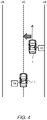
- FIG. 1 is a schematic diagram showing a configuration example of a vehicle 1 and a vehicle control system 10 according to the present embodiment.
- the vehicle 1 is provided with a wheel 2 and a steering wheel 3.
- the steering wheel 3 is an operation member that a driver of the vehicle 1 uses for a steering operation.
- a steering shaft 4 is coupled with the steering wheel 3 and rotates together with the steering wheel 3.
- the vehicle 1 is a vehicle of a steer-by-wire type, and the wheel 2 and the steering wheel 3 are mechanically disconnected from each other.
- the vehicle control system 10 controls the vehicle 1 of the steer-by-wire type.
- the vehicle control system 10 includes a turning device 20, a reaction force device 30, a driving environment information acquisition device 40, and a control device 100.
- the turning device 20 turns the wheel 2.
- turning the wheel 2 means changing a direction of the wheel 2 for making a turn.
- the turning device 20 includes a turning actuator 21 for turning the wheel 2.
- the turning actuator 21 is a turning motor.
- a rotor or the turning motor is connected to a turning bar 23 through a speed reducer 22.
- the turning bar 23 is coupled with the wheel 2.
- the turning motor rotates, its rotational motion is converted into a linear motion of the turning bar 23, and thereby the wheel 2 turns (i.e. changes its direction). That is, actuating the turning motor makes it possible to turn the wheel 2.
- the operation of the turning actuator 21 is controlled by the control device 100.
- the reaction force device 30 applies a steering reaction force (reaction torque) to the steering wheel 3.
- the reaction force device 30 includes a reaction force actuator 31 for applying the steering reaction force to the steering wheel 3.
- the reaction force actuator 31 is a reaction force motor. Actuating the reaction force motor makes it possible to apply the steering reaction force to the steering shaft 4 and thus to the steering wheel 3.
- the operation of the reaction force actuator 31 is controlled by the control device 100.
- the driving environment information acquisition device 40 acquires driving environment information ENV indicating a driving environment for the vehicle 1.
- the driving environment information acquisition device 40 includes a vehicle state sensor 50, a recognition sensor 60, and the like.
- the vehicle state sensor 50 detects a state of the vehicle 1.
- the vehicle state sensor 50 includes a steering angle sensor 51, a steering torque sensor 52, a rotational angle sensor 53, a rotational angle sensor 54, a turning current sensor 55, a vehicle speed sensor 56, and the like.
- the steering angle sensor 51 detects a steering angle ⁇ s (i.e., a steering wheel angle) of the steering wheel 3.
- the steering torque sensor 52 detects a steering torque Ts applied to the steering shaft 4.
- the rotational angle sensor 53 detects a rotation angle ⁇ of the reaction force actuator 31 (e.g., the reaction force motor).
- the rotational angle sensor 54 detects a rotation angle of the turning actuator 21 (e.g., the turning motor).
- the rotation angle of the turning motor corresponds to a turn angle (i.e., an actual turn angle 8a) of the wheel 2. It can be also said that the rotational angle sensor 54 detects the actual turn angle ⁇ a of the wheel 2.
- the turning current sensor 55 detects a turning current Im that drives the turning actuator 21.
- the vehicle speed sensor 56 detects a vehicle speed V being a speed of the vehicle 1.
- the vehicle state sensor 50 may include a yaw rate sensor and an acceleration sensor.
- the recognition sensor 60 recognizes (detects) a situation around the vehicle 1.
- Examples of the recognition sensor 60 include a camera, a LIDAR (Laser Imaging Detection and Ranging), a radar, and the like.
- the driving environment information acquisition device 40 may further include a position sensor that acquires a position of the vehicle 1.
- the position sensor is exemplified by a GPS (Global Positioning System) sensor.
- the driving environment information acquisition device 40 may acquire map information.
- the driving environment information ENV includes vehicle state information and surrounding situation information.
- the vehicle state information indicates the vehicle state detected by the vehicle state sensor 50.
- the surrounding situation information indicates results of recognition by the recognition sensor 60.
- the surrounding situation information includes an image captured by the camera.
- the surrounding situation information may include object information about objects around the vehicle 1. Examples of the objects around the vehicle 1 include a pedestrian, another vehicle (e.g., a preceding vehicle, a parked vehicle, etc.), a sign, a white line, a roadside structure, and the like.
- the object information indicates a relative position and a relative velocity of the object with respect to the vehicle 1.
- the driving environment information ENV may further include the position information of the vehicle 1, the map information, and the like.
- the control device (controller) 100 controls the vehicle 1.
- the control device 100 includes one or more processors 110 (hereinafter simply referred to as a processor 110) and one or more memory devices 120 (hereinafter simply referred to as a memory devices 120).
- the processor 110 executes a variety of processing.
- the processor 110 includes a CPU (Central Processing Unit).
- the memory device (memory) 120 stores a variety of information necessary for the processing by the processor 110. Examples of the memory device 120 include a volatile memory, a nonvolatile memory, an HDD (Hard Disk Drive), an SSD (Solid State Drive), and the like.
- the control device 100 may include one or more ECUs (Electronic Control Units).
- control device 100 The variety of processing by the control device 100 is implemented by the processor 110 executing a control program being a computer program.
- the control program is stored in the memory device 120.
- the control program may be recorded on a non-transitory computer-readable recording medium.
- the control device 100 acquires the driving environment information ENV from the driving environment information acquisition device 40.
- the driving environment information ENV is stored in the memory device 120.
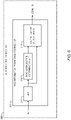
- FIG. 2 is a block diagram showing a functional configuration of the control device 100.
- the control device 100 includes a turning control unit 200, a reaction force control unit 300, and a driving assist control unit 400 as functional blocks. These functional blocks are realized by a cooperation of the processor 110 executing the control program and the memory device 120. It should be noted that the turning control unit 200, the reaction force control unit 300, and the driving assist control unit 400 may be realized by different control devices, respectively. In that case, the control devices are communicably connected to each other and communicate necessary information with each other.
- the turning control unit 200 executes "turning control” that turns the wheel 2. More specifically, the turning control unit 200 turns (i.e., changes a direction of) the wheel 2 by controlling the turning actuator 21 of the turning device 20.
- the turning control unit 200 executes the turning control in response to a steering operation of the steering wheel 3 performed by the driver. For example, the turning control unit 200 calculates a target turn angle ⁇ t based on the steering angle ⁇ s and the vehicle speed V. The steering angle ⁇ s is detected by the steering angle sensor 51. As another example, the steering angle ⁇ s may be calculated from the rotation angle ⁇ detected by the rotational angle sensor 53. The vehicle speed V is detected by the vehicle speed sensor 56. The turning control unit 200 turns the wheel 2 according to the target turn angle ⁇ t. The actual turn angle ⁇ a of the wheel 2 is detected by the rotational angle sensor 54. The turning control unit 200 controls the turning actuator 21 such that the actual turn angle ⁇ a follows the target turn angle ⁇ t.
- the turning control unit 200 generates a control signal for driving the turning actuator 21 based on a deviation between the target turn angle ⁇ t and the actual turn angle ⁇ a of the wheel 2.
- the turning actuator 21 is driven according to the control signal, and thereby the wheel 2 is turned.
- a current driving the turning actuator 21 at this time is the turning current Im.
- the turning control unit 200 executes the turning control according to a request from the driving assist control unit 400 described later.
- the turning control unit 200 acquires a target control amount from the driving assist control unit 400 and executes the turning control according to the target control amount.
- the reaction force control unit 300 executes "reaction force control” that applies the steering reaction force (reaction torque) to the steering wheel 3. More specifically, the reaction force control unit 300 applies the steering reaction force to the steering wheel 3 by controlling the reaction force actuator 31 of the reaction force device 30.
- the reaction force control unit 300 executes the reaction force control in response to the steering operation of the steering wheel 3 performed by the driver. For example, the reaction force control unit 300 calculates a target steering reaction force (spring component) corresponding to a self-aligning torque applied to the wheel 2, based on the steering angle ⁇ s and the vehicle speed V.
- the target steering reaction force may further include a damping component according to a steering speed (d ⁇ s/dt).
- the reaction force control unit 300 controls the reaction force actuator 31 so as to generate the target steering reaction force. More specifically, the reaction force control unit 300 generates a control signal for driving the reaction force actuator 31 based on the target steering reaction force.
- the reaction force actuator 31 is driven according to the control signal, and thereby the steering reaction force is generated.
- reaction force control unit 300 may execute the reaction force control according to a request from the driving assist control unit 400 described later.
- the driving assist control unit 400 executes "driving assist control" that assists driving of the vehicle 1.
- the driving assist control automatically controls travel of the vehicle 1 independently of a driving operation by the driver.
- the driving assist control related to steering will be considered in particular. Examples of such the driving assist control include automated driving control, risk avoidance control, lane keep assist control (LTA: Lane Tracing Assist), lane departure suppression control (LDA: Lane Departure Alert), and the like.
- the automated driving control controls automated driving of the vehicle 1. More specifically, the driving assist control unit 400 generates a travel plan of the vehicle 1 based on the driving environment information ENV. Examples of the travel plan include keeping a current travel lane, making a lane change, making a right or left turn, avoiding an obstacle, and the like. Furthermore, the driving assist control unit 400 generates a target trajectory TRJ necessary for the vehicle 1 to travel in accordance with the travel plan, based on the driving environment information ENV. The target trajectory TRJ includes a target position and a target speed. Then, the driving assist control unit 400 performs vehicle travel control such that the vehicle 1 follows the target trajectory TRJ.
- the driving assist control unit 400 calculates a deviation (e.g., a lateral deviation, a yaw angle deviation, and a speed deviation) between the vehicle 1 and the target trajectory TRJ, and calculates a target control amount necessary for reducing the deviation.
- the target control amount include a target turn angle, a target yaw rate, a target speed, a target acceleration, a target deceleration, a target current, and the like.
- the driving assist control unit 400 performs the vehicle travel control according to the target control amount.
- the vehicle travel control includes turning control, acceleration control, and deceleration control.
- the turning control is performed through the turning control unit 200 described above.
- the acceleration control and the deceleration control are performed by controlling a driving device and a braking device (not shown) of the vehicle 1.
- FIG. 3 is a conceptual diagram for explaining the risk avoidance control.
- the risk avoidance control is the driving assist control for reducing a risk of collision with an object existing ahead of the vehicle 1.
- Examples of the object as the avoidance target include a pedestrian, a bicycle, a motorcycle, an animal, another vehicle, and the like.
- the driving assist control unit 400 recognizes the object existing ahead of the vehicle 1 based on the surrounding situation information (object information) included in the driving environment information ENV. For example, when the risk of collision with the recognized object exceeds a threshold, the driving assist control unit 400 executes the risk avoidance control. More specifically, the driving assist control unit 400 generates a target trajectory TRJ moving in a direction away from the object in order to secure a lateral distance to the object. Then, the driving assist control unit 400 performs the vehicle travel control such that the vehicle 1 follows the target trajectory TRJ.
- the vehicle travel control here includes at least one of the turning control and the deceleration control. The turning control is performed through the turning control unit 200 described above.
- FIG. 4 is a conceptual diagram for explaining the lane keep assist control.
- the lane keep assist control is the driving assist control for assisting the vehicle 1 to travel along a lane center LC.
- the lane is an area sandwiched between left and right lane boundaries LB. Examples of the lane boundary LB include a white line (lane marking), a curb, and the like.
- the lane center LC is a center line of the lane.
- the driving assist control unit 400 recognizes the lane boundary LB and the lane center LC based on the surrounding situation information included in the driving environment information ENV. When the vehicle 1 deviates from the lane center LC, the driving assist control unit 400 executes the lane keep assist control. More specifically, the driving assist control unit 400 executes the turning control such that the vehicle 1 returns back to the lane center LC.
- the turning control is performed through the turning control unit 200 described above.
- FIG. 5 is a conceptual diagram for explaining the lane departure suppression control.
- the lane departure suppression control is the driving assist control for suppressing the vehicle 1 from departing from a travel lane.
- the driving assist control unit 400 recognizes the lane boundary LB based on the surrounding situation information included in the driving environment information ENV. When a distance between the vehicle 1 and the lane boundary LB becomes less than a predetermined threshold, the driving assist control unit 400 executes the lane departure suppression control. More specifically, the driving assist control unit 400 notifies the driver of a possibility of the lane departure. For example, the driving assist control unit 400 vibrates the steering wheel 3 by controlling a steering wheel vibration mechanism (not shown). The driving assist control unit 400 may output an alert through display and/or audio. Moreover, the driving assist control unit 400 may execute the turning control such that the vehicle 1 moves toward the lane center LC. The turning control is performed through the turning control unit 200 described above.
- the reaction force control according to the present embodiment includes at least one of the “road information transmission control” and the “deviation compensation control”, in addition to a common reaction force control that simulates the self-aligning torque.
- the “road information transmission control” and the “deviation compensation control” will be described in detail.
- the road information transmission control is the reaction force control intended to notify the driver of road surface unevenness (road information).
- the road information transmission control detects a high-frequency oscillation caused by the road surface unevenness and applies a steering reaction force component corresponding to the high-frequency oscillation to the steering wheel 3 (see Patent Literature 2).
- FIG. 6 is a diagram for explaining the road information transmission control according to the present embodiment.
- the reaction force control unit 300 includes a road information transmission control unit 310.
- the road information transmission control unit 310 detects the high-frequency oscillation caused by the road surface unevenness, based on the turning current Im.
- the turning current Im is detected by the turning current sensor 55. Then, the road information transmission control unit 310 calculates a target control amount CON_RI for generating the steering reaction force component corresponding to the high-frequency oscillation.
- the road information transmission control unit 310 includes a bandpass filter 311, a road surface state determination unit 312, and a control amount calculation unit 313.
- the bandpass filter 311 extracts signals of a predetermined frequency range from a signal of the turning current Im.
- the predetermined frequency range is set to correspond to a frequency range of the high-frequency oscillation caused by the road surface unevenness.
- the road surface state determination unit 312 determines whether a road surface is a flat road or a rough road based on filtered turning current Im. For example, the road surface state determination unit 312 compares the turning current Im with a predetermined current threshold to count the number of times that the turning current Im exceeds the predetermined current threshold within a certain period of time. When the number of times is equal to or larger than a threshold, the road surface state determination unit 312 determines that the road surface is the rough road, that is, there is the road surface unevenness. As another example, when the turning current Im exceeds a dead band, the road surface state determination unit 312 may determine that there is the road surface unevenness.
- the control amount calculation unit 313 calculates the target control amount CON_RI for generating the steering reaction force component corresponding to the high-frequency oscillation caused by the road surface unevenness. For example, the control amount calculation unit 313 calculates the target control amount CON_RI by multiplying the filtered turning current Im by a predetermined gain.
- the reaction force control unit 300 calculates a final target control amount by combining the target control amount CON RI caused by the road information transmission control and another target control amount caused by another type of reaction force control. Then, the reaction force control unit 300 executes the reaction force control by controlling the reaction force actuator 31 of the reaction force device 30 in accordance with the final target control amount.
- the driving assist control In a situation where the driving assist control and the road information transmission control are simultaneously in operation, the following problem is caused.
- the driving assist control When the driving assist control is in operation, the driver does not necessarily have a steering intention. If the road information transmission control is performed although the driver does not have the steering intention, the driver feels annoyed for the high-frequency oscillation of the steering wheel 3.
- the reaction force control unit 300 deactivates the road information transmission control.
- “Deactivating the road information transmission control” means setting the steering reaction force component caused by the road information transmission control to zero.
- the reaction force control unit 300 acquires a steering parameter that reflects the steering intention of the driver.
- the steering torque Ts is used as the steering parameter reflecting the steering intention of the driver.
- the steering torque Ts is detected by the steering torque sensor 52.
- the reaction force control unit 300 sets a threshold Tth_RI, and compares the steering parameter with the threshold Tth_RI.
- a deactivation condition for deactivating the road information transmission control is that "the driving assist control is in operation and the steering parameter is less than the threshold Tth_RI.”
- the reaction force control unit 300 deactivates the road information transmission control, that is, sets the steering reaction force component caused by the road information transmission control to zero. This makes it possible to suppress the driver from feeling annoyed when there is no or weak steering intention of the driver.
- a "steering determination threshold Tth_S" used for driver's steering determination is considered.
- the steering determination threshold Tth_S is used for the driver's steering determination.
- the control device 100 determines that the driver is not steering the steering wheel 3 and sets a driver's steering flag to OFF.
- the steering parameter is equal to or greater than the steering determination threshold Tth_S, the control device 100 determines that the driver is steering the steering wheel 3 and sets the driver's steering flag to ON.
- the steering determination threshold Tth_S may be set to different values depending on the type of the driving assist control being in operation. For example, in a case of the automated driving control, the steering determination threshold Tth_S is set relatively high in order to suppress an erroneous determination. As another example, in a case of the lane keep assist control, the steering determination threshold Tth_S is set relatively low.
- FIG. 7 is a diagram for explaining an example of the deactivation of the road information transmission control.
- a horizontal axis represents time, and a vertical axis represents the steering parameter (e.g., the steering torque Ts).
- the deactivation condition for deactivating the road information transmission control is that "the driving assist control is in operation and the driver's steering flag is OFF.”
- FIG. 8 is a diagram for explaining another example of the deactivation of the road information transmission control.
- the threshold Tth_RI regarding the road information transmission control is set to be higher than 0 and less than the steering determination threshold Tth_S. Even in this case, at least the effect of reducing the driver's feeling of annoyance can be obtained.
- the reaction force control unit 300 may gradually increase an output gain of the road information transmission control as the steering torque Ts increases from the threshold Tth RI and becomes closer to the steering determination threshold Tth_S.
- FIG. 9 is a block diagram showing a functional configuration example related to the road information transmission control according to the present embodiment.
- the reaction force control unit 300 includes the road information transmission control unit 310, a deactivation condition determination unit 320, a gain switching unit 321, and a multiplier unit 322.
- the reaction force control unit 300 may further include a guard unit 323.
- the road information transmission control unit 310 calculates the target control amount CON RI based on the turning current Im (see FIG. 6 ).
- the target control amount CON_RI calculated by the road information transmission control unit 310 is hereinafter referred to as a "target control amount CON_RI0.”
- the deactivation condition determination unit 320 determines whether or not the deactivation condition is satisfied based on driving assist control state information STA and the steering parameter (e.g., the steering torque Ts).
- the driving assist control state information STA includes information indicating whether or not the driving assist control is in operation.
- the driving assist control state information STA is given from the driving assist control unit 400.
- the deactivation condition is that "the driving assist control is in operation and the steering parameter is less than the threshold Tth RI.”
- the gain switching unit 321 switches a control amount gain Ga according to a result of determination by the deactivation condition determination unit 320. More specifically, when the deactivation condition is satisfied, the gain switching unit 321 sets the control amount gain Ga to "0.” On the other hand, when the deactivation condition is not satisfied, the gain switching unit 321 sets the control amount gain Ga to "1.”
- the control amount gain Ga is set to "0."
- the target control amount CON RI also becomes zero, and thus the steering reaction force component caused by the road information transmission control also becomes zero. That is, the road information transmission control is deactivated (turned OFF).
- FIG. 10 is a diagram for explaining the change in the control amount gain Ga.
- the control amount gain Ga gradually changes from "0" to "1.”
- Respective time variations of the target control amounts CON_RI0 and CON_RI also are shown in FIG. 10 .
- a variation time of the control amount gain Ga is set to half the " inverse number of a main frequency component of the target control amount CON_RI0.”
- a variation gradient of the target control amount CON RI becomes less than a variation gradient of the original target control amount CON_RI0.
- a rapid change in the steering reaction force is suppressed.
- the deactivation condition for deactivating the road information transmission control will be described below.
- the driving assist control is the "lane departure suppression control (LDA)"
- LDA lane departure suppression control
- the lane departure suppression control vibrates the steering wheel 3 for notifying the driver of a possibility of the lane departure. If the road information transmission control operates when such the lane departure suppression control is in operation, interference or resonance between the steering wheel vibrations due to both the control may be caused. When the interference or resonance between the steering wheel vibrations occurs, the steering wheel vibration amount becomes insufficient or excessive, and thus the warning effect obtained by the lane departure suppression control is reduced.
- the reaction force control unit 300 sets the steering reaction force component caused by the road information transmission control to zero. That is, the deactivation condition according to the modification example is that "the lane departure suppression control is in operation.” This makes it possible to suppress the interference or resonance between the steering wheel vibrations when the lane departure suppression control is in operation and thus to suppress reduction in warning effect obtained by the lane departure suppression control.
- FIG. 11 is a block diagram showing a functional configuration example related to the road information transmission control according to the modification example.
- the deactivation condition determination unit 320 determines whether or not the deactivation condition is satisfied based on the driving assist control state information STA.
- the driving assist control state information STA indicates the type of the driving assist control being in operation, in addition to whether or not the driving assist control is in operation. Others are the same as in the case of the functional configuration example shown in FIG. 9 .
- the steering reaction force component caused by the road information transmission control is set to zero.
- a first example of the deactivation condition is that the driving assist control is in operation and the steering parameter reflecting the steering intention of the driver is less than the threshold Tth_RI. This deactivation condition makes it possible to suppress the driver from feeling annoyed when there is no or weak steering intention of the driver.
- a second example of the deactivation condition is that the lane departure suppression control that vibrates the steering wheel 3 for notifying the driver of a possibility of the lane departure is in operation.
- This deactivation condition makes it possible to suppress the interference or resonance between the steering wheel vibrations and thus to suppress reduction in warning effect obtained by the lane departure suppression control.
- the turning control unit 200 executes the turning control in response to a steering operation of the steering wheel 3 performed by the driver. For example, the turning control unit 200 calculates the target turn angle ⁇ t based on the steering angle ⁇ s and the vehicle speed V. Then, the turning control unit 200 controls the turning actuator 21 such that the actual turn angle ⁇ a of the wheel 2 follows the target turn angle ⁇ t.
- a deviation (gap) may occur between the steering operation by the driver and the turning of the wheel 2. For example, when the driver rotates the steering wheel 3 at a considerable speed, a deviation (gap) between the target turn angle ⁇ t and the actual turn angle ⁇ a may occur due to a response delay of the turning actuator 21.
- Deviation compensation control is the reaction force control intended to reduce the deviation between the steering operation by the driver and the turning of the wheel 2.
- the target turn angle ⁇ t according to the steering operation by the driver is hereinafter referred to as a "first target turn angle ⁇ t1.”
- the deviation compensation control detects a deviation between the first target turn angle ⁇ t1 and the actual turn angle ⁇ a and applies a steering reaction force component to the steering wheel 3 in a direction of reducing the deviation. That is to say, the deviation compensation control applies a steering reaction force component to the steering wheel 3 in a direction that hinders the driver's steering operation. As a result, it becomes harder for the driver to rotate the steering wheel 3, and thus the deviation is expected to be reduced.
- FIG. 12 is a block diagram for explaining the deviation compensation control according to the present embodiment.
- the reaction force control unit 300 includes a deviation compensation control unit 330.
- the deviation compensation control unit 330 includes a deviation calculation unit 331 and a control amount calculation unit 332.
- the deviation calculation unit 331 calculates the deviation between the first target turn angle ⁇ t1 and the actual turn angle ⁇ a.
- the first target turn angle ⁇ t1 is calculated by the turning control unit 200.
- the actual turn angle ⁇ a is obtained from the rotational angle sensor 54.
- the control amount calculation unit 332 calculates a target control amount CON_DC for generating a steering reaction force component in a direction of reducing the deviation. For example, the control amount calculation unit 332 calculates the target control amount CON_DC such that the steering reaction force increases as the deviation becomes larger.
- the reaction force control unit 300 calculates a final target control amount by combining the target control amount CON_DC caused by the deviation compensation control and another target control amount caused by another type of reaction force control. Then, the reaction force control unit 300 executes the reaction force control by controlling the reaction force actuator 31 of the reaction force device 30 in accordance with the final target control amount.
- the target turn angle ⁇ t required by the driving assist control is hereinafter referred to as a "second target turn angle ⁇ t2.”
- a final target turn angle ⁇ t is determined by combining the first target turn angle ⁇ t1 and the second target turn angle ⁇ t2.
- turn angle distribution control Such the process of combining the first target turn angle ⁇ t1 and the second target turn angle ⁇ t2 to determine the target turn angle ⁇ t is hereinafter referred to as "turn angle distribution control.”
- the predetermined condition for performing the turn angle distribution control is hereinafter referred to as a “turn angle distribution condition.”
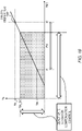
- FIG. 13 is a diagram for explaining an example of the turn angle distribution control.
- a horizontal axis represents time, and a vertical axis represents the steering parameter.
- the steering parameter which is a parameter reflecting the steering intention of the driver, is for example the steering torque Ts.
- the steering determination threshold Tth_S is a threshold used for the driver's steering determination.
- the control device 100 determines that the driver is steering the steering wheel 3 and sets the driver's steering flag to ON.
- An intervention threshold Tth_I is less than the steering determination threshold Tth_S.
- the turn angle distribution condition is that the steering parameter is in a range from the intervention threshold Tth I (first threshold) to the steering determination threshold Tth_S (second threshold).
- the steering parameter gradually increases with time.
- the steering parameter reaches the intervention threshold Tth_I.
- the turn angle distribution control is started.
- the steering parameter reaches the steering determination threshold Tth_S.
- a period Pd from the time t1 and the time t2 is the period in which the turn angle distribution condition is satisfied and the turn angle distribution control is performed.
- FIG. 14 shows an example of distribution ratios of the first target turn angle ⁇ t1 and the second target turn angle ⁇ t2 in the turn angle distribution control.
- a horizontal axis represents the steering parameter
- a vertical axis represents the distribution ratio. It can be said that the distribution ratio is a rate of contribution to the final target turn angle ⁇ t.
- the distribution ratio of the first target turn angle ⁇ t1 increases while the distribution ratio of the second target turn angle ⁇ t2 decreases.
- the distribution ratio of the first target turn angle ⁇ t1 is 0% and the distribution ratio of the second target turn angle ⁇ t2 is 100%.
- the steering parameter is equal to the steering determination threshold Tth_S
- the distribution ratio of the first target turn angle ⁇ t1 is 100% and the distribution ratio of the second target turn angle ⁇ t2 is 0%.
- FIG. 15 is a block diagram for explaining processing related to the turn angle distribution control.
- the turning control unit 200 includes a target turn angle calculation unit 210 and a turn angle distribution control unit 220.
- the target turn angle calculation unit 210 calculates the first target turn angle ⁇ t1 according to the steering operation of the steering wheel 3 by the driver. For example, the target turn angle calculation unit 210 calculates the first target turn angle ⁇ t1 based on the steering angle ⁇ s and the vehicle speed V.
- the steering angle ⁇ s is detected by the steering angle sensor 51.
- the steering angle ⁇ s may be calculated from the rotation angle ⁇ detected by the rotational angle sensor 53.
- the vehicle speed V is detected by the vehicle speed sensor 56.
- the turn angle distribution control unit 220 receives the first target turn angle ⁇ t1, the second target turn angle ⁇ t2, the driving assist control state information STA, and the steering parameter.
- the second target turn angle ⁇ t2 is given from the driving assist control unit 400.
- the second target turn angle ⁇ t2 may be calculated based on the target control amount given from the driving assist control unit 400.
- the driving assist control state information STA which includes information indicating whether or not the driving assist control is in operation, is given from the driving assist control unit 400.
- the turn angle distribution control unit 220 determines whether or not the turn angle distribution condition is satisfied based on the steering parameter.
- the turn angle distribution condition is that the steering parameter is in a range from the intervention threshold Tth I (first threshold) to the steering determination threshold Tth_S (second threshold).
- Tth I first threshold
- Tth_S second threshold
- the turn angle distribution control unit 220 determines the target turn angle ⁇ t by combining the first target turn angle ⁇ t1 and the second target turn angle ⁇ t2. Then, the turning control unit 200 performs the turning control according to the target turn angle ⁇ t.
- FIG. 16 is a diagram for explaining the problem.
- a horizontal axis represents time, and a vertical axis represents the first target turn angle ⁇ t1, the second target turn angle ⁇ t2, and the target turn angle ⁇ t.
- the actual turn angle ⁇ a follows the target turn angle ⁇ t.
- the actual turn angle ⁇ a and the target turn angle ⁇ t are regarded as equivalent.
- the driver starts steering.
- the first target turn angle ⁇ t1 according to the driver's steering operation increases with time.
- the period Pd in which the turn angle distribution control is performed is the same as in the case shown in FIG. 13 described above.
- the target turn angle ⁇ t is equal to the first target turn angle ⁇ t1 and the actual turn angle ⁇ a follows the first target turn angle ⁇ t1.
- the target turn angle ⁇ t is different from the first target turn angle ⁇ t1 and thus a deviation occurs between the actual turn angle ⁇ a and the first target turn angle ⁇ t1.
- the target turn angle ⁇ t is different from the first target turn angle ⁇ t1 and thus a deviation occurs between the actual turn angle ⁇ a and the first target turn angle ⁇ t1.
- the deviation compensation control applies the steering reaction force component to the steering wheel 3 in a direction of reducing the deviation. That is to say, the deviation compensation control applies the steering reaction force component to the steering wheel 3 in a direction that hinders the driver's steering operation.
- the deviation here is not caused by the response delay of the turning actuator 21, and the deviation compensation control does not bring about its intended function effect. Rather, the deviation compensation control unnecessarily interferes the driver's steering operation and deteriorates operability of the steering wheel 3.
- the reaction force control unit 300 deactivates the deviation compensation control in at least a part of the period Pd in which the turn angle distribution condition is satisfied.
- “Deactivating the deviation compensation control” means setting the steering reaction force component caused by the deviation compensation control to zero. This makes it possible to suppress the deviation compensation control from unnecessarily interfering the steering operation. That is, reduction in operability of the steering wheel 3 is suppressed.
- the reaction force control unit 300 deactivates the deviation compensation control at least when the turn angle distribution condition is satisfied. This means that the deviation compensation control is deactivated in the whole period Pd in which the turn angle distribution condition is satisfied. As a result, the reduction in operability of the steering wheel 3 is more effectively suppressed.
- the turn angle distribution condition is that the steering parameter is in the range from the intervention threshold Tth_I (first threshold) to the steering determination threshold Tth_S (second threshold).
- the reaction force control unit 300 may set a threshold Tth_DC and compare the steering parameter with the threshold Tth_DC.
- the threshold Tth DC is set to be greater than the intervention threshold Tth_I and equal to or less than the steering determination threshold Tth_S.
- the reaction force control unit 300 deactivates the deviation compensation control.
- the deviation compensation control is deactivated in at least a part of the period Pd in which the turn angle distribution condition is satisfied. It can be said that a deactivation condition for deactivating the deviation compensation control is that "the driving assist control is in operation and the steering parameter is less than the threshold Tth_DC.”
- FIG. 17 is a diagram for explaining an example of the deactivation of the deviation compensation control. Its format is the same as that of FIG. 13 described above.
- the horizontal axis represents the time, and the vertical axis represents the steering parameter (e.g., the steering torque Ts).
- the deactivation condition for deactivating the deviation compensation control is that "the driving assist control is in operation and the driver's steering flag is OFF.”
- the deactivation condition is satisfied and the deviation compensation control is deactivated.
- the reduction in operability of the steering wheel 3 is effectively suppressed.
- FIG. 18 is a diagram for explaining another example of the deactivation of the deviation compensation control.
- the threshold Tth_DC regarding the deviation compensation control is set to be greater than the intervention threshold Tth_I and less than the steering determination threshold Tth_S (i.e., Tth_I ⁇ Tth_DC ⁇ Tth_S).
- Tth_I ⁇ Tth_DC ⁇ Tth_S the steering determination threshold
- FIG. 19 is a block diagram showing a functional configuration example related to the deviation compensation control according to the present embodiment.
- the reaction force control unit 300 includes the deviation compensation control unit 330, a deactivation condition determination unit 340, a gain switching unit 341, and a multiplier unit 342.
- the reaction force control unit 300 may further include a guard unit 343.
- the deviation compensation control unit 330 calculates the target control amount CON_DC based on the first target turn angle ⁇ t1 and the actual turn angle ⁇ a (see FIG. 12 ).
- the target control amount CON_DC calculated by the deviation compensation control unit 330 is hereinafter referred to as a "target control amount CON_DC0.”
- the deactivation condition determination unit 340 determines whether or not the deactivation condition is satisfied based on driving assist control state information STA and the steering parameter (e.g., the steering torque Ts).
- the driving assist control state information STA includes information indicating whether or not the driving assist control is in operation.
- the driving assist control state information STA is given from the driving assist control unit 400.
- the deactivation condition is that "the turn angle distribution condition is satisfied during operation of the driving assist control.”
- the deactivation condition is that" the driving assist control is in operation and the steering parameter is less than the threshold Tth_DC.”
- the gain switching unit 341 switches a control amount gain Gb according to a result of determination by the deactivation condition determination unit 340. More specifically, when the deactivation condition is satisfied, the gain switching unit 341 sets the control amount gain Gb to "0.” On the other hand, when the deactivation condition is not satisfied, the gain switching unit 341 sets the control amount gain Gb to "1"
- the control amount gain Gb is set to "0."
- the target control amount CON_DC also becomes zero, and thus the steering reaction force component caused by the deviation compensation control also becomes zero. That is, the deviation compensation control is deactivated (turned OFF).
- FIG. 20 is a diagram for explaining the change in the control amount gain Gb.
- the control amount gain Gb gradually changes from "0" to "1.”
- Respective time variations of the target control amounts CON_DC0 and CON_DC also are shown in FIG. 20 .
- a variation time of the control amount gain Gb is set to half the " inverse number of a main frequency component of the target control amount CON_DC0.”
- a variation gradient of the target control amount CON_DC becomes less than a variation gradient of the original target control amount CON_DC0.
- a rapid change in the steering reaction force is suppressed.
- the steering reaction force component caused by the deviation compensation control is set to zero in at least a part of the period Pd in which the turn angle distribution condition is satisfied. This makes it possible to suppress the deviation compensation control from unnecessarily interfering the steering operation. It is thus possible to suppress reduction in operability of the steering wheel 3.
Applications Claiming Priority (1)
| Application Number | Priority Date | Filing Date | Title |
|---|---|---|---|
| JP2021069757A JP2022164333A (ja) | 2021-04-16 | 2021-04-16 | 車両制御システム及び車両制御方法 |
Publications (2)
| Publication Number | Publication Date |
|---|---|
| EP4074580A1 true EP4074580A1 (de) | 2022-10-19 |
| EP4074580B1 EP4074580B1 (de) | 2023-11-15 |
Family
ID=80999652
Family Applications (1)
| Application Number | Title | Priority Date | Filing Date |
|---|---|---|---|
| EP22165518.6A Active EP4074580B1 (de) | 2021-04-16 | 2022-03-30 | Fahrzeugsteuerungssystem und fahrzeugsteuerungsverfahren |
Country Status (4)
| Country | Link |
|---|---|
| US (1) | US20220332367A1 (de) |
| EP (1) | EP4074580B1 (de) |
| JP (1) | JP2022164333A (de) |
| CN (1) | CN115214762B (de) |
Families Citing this family (2)
| Publication number | Priority date | Publication date | Assignee | Title |
|---|---|---|---|---|
| KR20230000030A (ko) * | 2021-06-23 | 2023-01-02 | 현대자동차주식회사 | 차량의 운전 보조 시스템 |
| JP2023005140A (ja) * | 2021-06-28 | 2023-01-18 | トヨタ自動車株式会社 | 車両制御システム及び車両制御方法 |
Citations (7)
| Publication number | Priority date | Publication date | Assignee | Title |
|---|---|---|---|---|
| DE19806458A1 (de) * | 1997-02-19 | 1998-08-20 | Koyo Seiko Co | Kraftfahrzeuglenkvorrichtung |
| JP2003002223A (ja) | 2001-06-20 | 2003-01-08 | Koyo Seiko Co Ltd | 車両の操舵装置 |
| EP1415894A2 (de) * | 2002-10-30 | 2004-05-06 | Koyo Seiko Co., Ltd. | Fahrzeuglenkung |
| EP1415893A2 (de) * | 2002-10-31 | 2004-05-06 | Koyo Seiko Co., Ltd. | Kraftfahrzeuglenkungseinrichtung |
| US20120081234A1 (en) * | 2010-09-30 | 2012-04-05 | Ford Global Technologies, Llc | Lane Departure Haptic Warning with Compensation for Road-Caused Vibration |
| US20190092338A1 (en) * | 2017-09-22 | 2019-03-28 | Subaru Corporation | Conveyance amount controlling apparatus |
| JP2020142704A (ja) | 2019-03-07 | 2020-09-10 | トヨタ自動車株式会社 | 車両制御システム |
Family Cites Families (12)
| Publication number | Priority date | Publication date | Assignee | Title |
|---|---|---|---|---|
| TW410201B (en) * | 1996-09-27 | 2000-11-01 | Toyoda Automatic Loom Works | Handle angle compensator in power steering apparatus and vehicle |
| US6931316B2 (en) * | 2002-06-05 | 2005-08-16 | Nissan Motor Co., Ltd. | Toroidal continuously variable transmission control apparatus |
| JP4294401B2 (ja) * | 2003-07-25 | 2009-07-15 | 富士重工業株式会社 | 車両用走行支援装置 |
| JP4466539B2 (ja) * | 2005-11-08 | 2010-05-26 | トヨタ自動車株式会社 | 内燃機関の制御装置 |
| JP4419997B2 (ja) * | 2006-08-28 | 2010-02-24 | トヨタ自動車株式会社 | 電動パワーステアリング装置 |
| JP5282889B2 (ja) * | 2009-01-13 | 2013-09-04 | トヨタ自動車株式会社 | 車両の操舵制御装置 |
| US9105190B2 (en) * | 2011-09-26 | 2015-08-11 | Toyota Jidosha Kabushiki Kaisha | Driving support system for a vehicle |
| EP3360758B1 (de) * | 2015-10-05 | 2021-06-09 | Hitachi Construction Machinery Co., Ltd. | Lenksteuerungsvorrichtung für ein nutzfahrzeug |
| JP6826377B2 (ja) * | 2016-05-27 | 2021-02-03 | 本田技研工業株式会社 | 車両用操舵装置 |
| EP3718858B1 (de) * | 2017-11-30 | 2023-05-03 | Jtekt Corporation | Fahrzeuglenkvorrichtung |
| JP6729838B2 (ja) * | 2018-03-06 | 2020-07-29 | 日産自動車株式会社 | 車両のステアリング制御方法および車両のステアリング制御装置 |
| JP7383384B2 (ja) * | 2019-03-05 | 2023-11-20 | 株式会社ジェイテクト | 操舵制御装置 |
-
2021
- 2021-04-16 JP JP2021069757A patent/JP2022164333A/ja active Pending
-
2022
- 2022-03-30 EP EP22165518.6A patent/EP4074580B1/de active Active
- 2022-03-31 US US17/709,558 patent/US20220332367A1/en active Pending
- 2022-04-13 CN CN202210388667.8A patent/CN115214762B/zh active Active
Patent Citations (7)
| Publication number | Priority date | Publication date | Assignee | Title |
|---|---|---|---|---|
| DE19806458A1 (de) * | 1997-02-19 | 1998-08-20 | Koyo Seiko Co | Kraftfahrzeuglenkvorrichtung |
| JP2003002223A (ja) | 2001-06-20 | 2003-01-08 | Koyo Seiko Co Ltd | 車両の操舵装置 |
| EP1415894A2 (de) * | 2002-10-30 | 2004-05-06 | Koyo Seiko Co., Ltd. | Fahrzeuglenkung |
| EP1415893A2 (de) * | 2002-10-31 | 2004-05-06 | Koyo Seiko Co., Ltd. | Kraftfahrzeuglenkungseinrichtung |
| US20120081234A1 (en) * | 2010-09-30 | 2012-04-05 | Ford Global Technologies, Llc | Lane Departure Haptic Warning with Compensation for Road-Caused Vibration |
| US20190092338A1 (en) * | 2017-09-22 | 2019-03-28 | Subaru Corporation | Conveyance amount controlling apparatus |
| JP2020142704A (ja) | 2019-03-07 | 2020-09-10 | トヨタ自動車株式会社 | 車両制御システム |
Also Published As
| Publication number | Publication date |
|---|---|
| CN115214762B (zh) | 2023-07-21 |
| JP2022164333A (ja) | 2022-10-27 |
| US20220332367A1 (en) | 2022-10-20 |
| CN115214762A (zh) | 2022-10-21 |
| EP4074580B1 (de) | 2023-11-15 |
Similar Documents
| Publication | Publication Date | Title |
|---|---|---|
| WO2018211802A1 (ja) | 自動運転支援装置および自動運転支援方法 | |
| EP4074580B1 (de) | Fahrzeugsteuerungssystem und fahrzeugsteuerungsverfahren | |
| US20200282990A1 (en) | Driving Control Apparatus for Vehicle | |
| US10913495B2 (en) | Vehicle safety steering system | |
| US8977420B2 (en) | Vehicle procession control through a traffic intersection | |
| US9569968B2 (en) | Method and device for the automated braking and steering of a vehicle | |
| JP7119428B2 (ja) | 運転支援装置 | |
| US20100228420A1 (en) | Model based predictive control for automated lane centering/changing control systems | |
| CN110536828B (zh) | 车辆控制方法及车辆控制装置 | |
| JP2004345518A (ja) | 車両用走行制御装置 | |
| CN108216365B (zh) | 驾驶支持器 | |
| JP6377942B2 (ja) | 運転支援装置 | |
| JP6614353B2 (ja) | 走行制御方法及び走行制御装置 | |
| EP3434546A1 (de) | Sensordefektkompensationssystem für ein automatisiertes systemfahrzeug | |
| JP5565053B2 (ja) | 先行車両検出装置およびこれを用いた衝突警報装置・衝突回避装置 | |
| US20200255012A1 (en) | Driving Control Apparatus for Vehicle | |
| US11225256B2 (en) | Vehicle control system and control method of vehicle | |
| US20220410968A1 (en) | Vehicle control system and vehicle control method | |
| US11254356B2 (en) | Vehicle control system | |
| WO2016186105A1 (ja) | 衝突回避方向を報知する衝突回避装置 | |
| CN108216209B (zh) | 驾驶支持器 | |
| EP4112422A1 (de) | Fahrzeugsteuerungssystem und fahrzeugsteuerungsverfahren | |
| WO2019088280A1 (ja) | 操舵制御装置、操舵制御方法及び記録媒体 | |
| US20190202493A1 (en) | Vehicle control apparatus | |
| JP2009073315A (ja) | 車両用制御装置 |
Legal Events
| Date | Code | Title | Description |
|---|---|---|---|
| PUAI | Public reference made under article 153(3) epc to a published international application that has entered the european phase |
Free format text: ORIGINAL CODE: 0009012 |
|
| STAA | Information on the status of an ep patent application or granted ep patent |
Free format text: STATUS: REQUEST FOR EXAMINATION WAS MADE |
|
| 17P | Request for examination filed |
Effective date: 20220330 |
|
| AK | Designated contracting states |
Kind code of ref document: A1 Designated state(s): AL AT BE BG CH CY CZ DE DK EE ES FI FR GB GR HR HU IE IS IT LI LT LU LV MC MK MT NL NO PL PT RO RS SE SI SK SM TR |
|
| GRAP | Despatch of communication of intention to grant a patent |
Free format text: ORIGINAL CODE: EPIDOSNIGR1 |
|
| STAA | Information on the status of an ep patent application or granted ep patent |
Free format text: STATUS: GRANT OF PATENT IS INTENDED |
|
| RIC1 | Information provided on ipc code assigned before grant |
Ipc: B62D 15/02 20060101ALI20230531BHEP Ipc: B62D 6/00 20060101AFI20230531BHEP |
|
| INTG | Intention to grant announced |
Effective date: 20230619 |
|
| GRAS | Grant fee paid |
Free format text: ORIGINAL CODE: EPIDOSNIGR3 |
|
| GRAA | (expected) grant |
Free format text: ORIGINAL CODE: 0009210 |
|
| STAA | Information on the status of an ep patent application or granted ep patent |
Free format text: STATUS: THE PATENT HAS BEEN GRANTED |
|
| AK | Designated contracting states |
Kind code of ref document: B1 Designated state(s): AL AT BE BG CH CY CZ DE DK EE ES FI FR GB GR HR HU IE IS IT LI LT LU LV MC MK MT NL NO PL PT RO RS SE SI SK SM TR |
|
| REG | Reference to a national code |
Ref country code: CH Ref legal event code: EP Ref country code: GB Ref legal event code: FG4D |
|
| REG | Reference to a national code |
Ref country code: DE Ref legal event code: R096 Ref document number: 602022000973 Country of ref document: DE |
|
| REG | Reference to a national code |
Ref country code: IE Ref legal event code: FG4D |
|
| REG | Reference to a national code |
Ref country code: LT Ref legal event code: MG9D |
|
| REG | Reference to a national code |
Ref country code: NL Ref legal event code: MP Effective date: 20231115 |
|
| PG25 | Lapsed in a contracting state [announced via postgrant information from national office to epo] |
Ref country code: GR Free format text: LAPSE BECAUSE OF FAILURE TO SUBMIT A TRANSLATION OF THE DESCRIPTION OR TO PAY THE FEE WITHIN THE PRESCRIBED TIME-LIMIT Effective date: 20240216 |
|
| PG25 | Lapsed in a contracting state [announced via postgrant information from national office to epo] |
Ref country code: IS Free format text: LAPSE BECAUSE OF FAILURE TO SUBMIT A TRANSLATION OF THE DESCRIPTION OR TO PAY THE FEE WITHIN THE PRESCRIBED TIME-LIMIT Effective date: 20240315 |
|
| PG25 | Lapsed in a contracting state [announced via postgrant information from national office to epo] |
Ref country code: LT Free format text: LAPSE BECAUSE OF FAILURE TO SUBMIT A TRANSLATION OF THE DESCRIPTION OR TO PAY THE FEE WITHIN THE PRESCRIBED TIME-LIMIT Effective date: 20231115 |
|
| REG | Reference to a national code |
Ref country code: AT Ref legal event code: MK05 Ref document number: 1631521 Country of ref document: AT Kind code of ref document: T Effective date: 20231115 |
|
| PG25 | Lapsed in a contracting state [announced via postgrant information from national office to epo] |
Ref country code: NL Free format text: LAPSE BECAUSE OF FAILURE TO SUBMIT A TRANSLATION OF THE DESCRIPTION OR TO PAY THE FEE WITHIN THE PRESCRIBED TIME-LIMIT Effective date: 20231115 |