EP4071902A1 - Batteriemodul, das eine feuerlöscheinheit aufweist, die löschmittel einschliesst - Google Patents
Batteriemodul, das eine feuerlöscheinheit aufweist, die löschmittel einschliesst Download PDFInfo
- Publication number
- EP4071902A1 EP4071902A1 EP20934601.4A EP20934601A EP4071902A1 EP 4071902 A1 EP4071902 A1 EP 4071902A1 EP 20934601 A EP20934601 A EP 20934601A EP 4071902 A1 EP4071902 A1 EP 4071902A1
- Authority
- EP
- European Patent Office
- Prior art keywords
- fire
- extinguishing
- battery module
- battery
- pack
- Prior art date
- Legal status (The legal status is an assumption and is not a legal conclusion. Google has not performed a legal analysis and makes no representation as to the accuracy of the status listed.)
- Granted
Links
Images


Classifications
-
- H—ELECTRICITY
- H01—ELECTRIC ELEMENTS
- H01M—PROCESSES OR MEANS, e.g. BATTERIES, FOR THE DIRECT CONVERSION OF CHEMICAL ENERGY INTO ELECTRICAL ENERGY
- H01M50/00—Constructional details or processes of manufacture of the non-active parts of electrochemical cells other than fuel cells, e.g. hybrid cells
- H01M50/30—Arrangements for facilitating escape of gases
- H01M50/383—Flame arresting or ignition-preventing means
-
- B—PERFORMING OPERATIONS; TRANSPORTING
- B26—HAND CUTTING TOOLS; CUTTING; SEVERING
- B26D—CUTTING; DETAILS COMMON TO MACHINES FOR PERFORATING, PUNCHING, CUTTING-OUT, STAMPING-OUT OR SEVERING
- B26D1/00—Cutting through work characterised by the nature or movement of the cutting member or particular materials not otherwise provided for; Apparatus or machines therefor; Cutting members therefor
- B26D1/0006—Cutting members therefor
-
- H—ELECTRICITY
- H01—ELECTRIC ELEMENTS
- H01M—PROCESSES OR MEANS, e.g. BATTERIES, FOR THE DIRECT CONVERSION OF CHEMICAL ENERGY INTO ELECTRICAL ENERGY
- H01M50/00—Constructional details or processes of manufacture of the non-active parts of electrochemical cells other than fuel cells, e.g. hybrid cells
- H01M50/20—Mountings; Secondary casings or frames; Racks, modules or packs; Suspension devices; Shock absorbers; Transport or carrying devices; Holders
- H01M50/233—Mountings; Secondary casings or frames; Racks, modules or packs; Suspension devices; Shock absorbers; Transport or carrying devices; Holders characterised by physical properties of casings or racks, e.g. dimensions
- H01M50/24—Mountings; Secondary casings or frames; Racks, modules or packs; Suspension devices; Shock absorbers; Transport or carrying devices; Holders characterised by physical properties of casings or racks, e.g. dimensions adapted for protecting batteries from their environment, e.g. from corrosion
-
- A—HUMAN NECESSITIES
- A62—LIFE-SAVING; FIRE-FIGHTING
- A62C—FIRE-FIGHTING
- A62C3/00—Fire prevention, containment or extinguishing specially adapted for particular objects or places
- A62C3/16—Fire prevention, containment or extinguishing specially adapted for particular objects or places in electrical installations, e.g. cableways
-
- A—HUMAN NECESSITIES
- A62—LIFE-SAVING; FIRE-FIGHTING
- A62C—FIRE-FIGHTING
- A62C35/00—Permanently-installed equipment
- A62C35/02—Permanently-installed equipment with containers for delivering the extinguishing substance
- A62C35/10—Containers destroyed or opened by flames or heat
-
- A—HUMAN NECESSITIES
- A62—LIFE-SAVING; FIRE-FIGHTING
- A62C—FIRE-FIGHTING
- A62C37/00—Control of fire-fighting equipment
- A62C37/08—Control of fire-fighting equipment comprising an outlet device containing a sensor, or itself being the sensor, i.e. self-contained sprinklers
- A62C37/10—Releasing means, e.g. electrically released
- A62C37/11—Releasing means, e.g. electrically released heat-sensitive
- A62C37/16—Releasing means, e.g. electrically released heat-sensitive with thermally-expansible links
-
- H—ELECTRICITY
- H01—ELECTRIC ELEMENTS
- H01M—PROCESSES OR MEANS, e.g. BATTERIES, FOR THE DIRECT CONVERSION OF CHEMICAL ENERGY INTO ELECTRICAL ENERGY
- H01M10/00—Secondary cells; Manufacture thereof
- H01M10/42—Methods or arrangements for servicing or maintenance of secondary cells or secondary half-cells
-
- H—ELECTRICITY
- H01—ELECTRIC ELEMENTS
- H01M—PROCESSES OR MEANS, e.g. BATTERIES, FOR THE DIRECT CONVERSION OF CHEMICAL ENERGY INTO ELECTRICAL ENERGY
- H01M50/00—Constructional details or processes of manufacture of the non-active parts of electrochemical cells other than fuel cells, e.g. hybrid cells
- H01M50/20—Mountings; Secondary casings or frames; Racks, modules or packs; Suspension devices; Shock absorbers; Transport or carrying devices; Holders
- H01M50/204—Racks, modules or packs for multiple batteries or multiple cells
- H01M50/207—Racks, modules or packs for multiple batteries or multiple cells characterised by their shape
- H01M50/209—Racks, modules or packs for multiple batteries or multiple cells characterised by their shape adapted for prismatic or rectangular cells
-
- H—ELECTRICITY
- H01—ELECTRIC ELEMENTS
- H01M—PROCESSES OR MEANS, e.g. BATTERIES, FOR THE DIRECT CONVERSION OF CHEMICAL ENERGY INTO ELECTRICAL ENERGY
- H01M50/00—Constructional details or processes of manufacture of the non-active parts of electrochemical cells other than fuel cells, e.g. hybrid cells
- H01M50/20—Mountings; Secondary casings or frames; Racks, modules or packs; Suspension devices; Shock absorbers; Transport or carrying devices; Holders
- H01M50/204—Racks, modules or packs for multiple batteries or multiple cells
- H01M50/207—Racks, modules or packs for multiple batteries or multiple cells characterised by their shape
- H01M50/211—Racks, modules or packs for multiple batteries or multiple cells characterised by their shape adapted for pouch cells
-
- H—ELECTRICITY
- H01—ELECTRIC ELEMENTS
- H01M—PROCESSES OR MEANS, e.g. BATTERIES, FOR THE DIRECT CONVERSION OF CHEMICAL ENERGY INTO ELECTRICAL ENERGY
- H01M50/00—Constructional details or processes of manufacture of the non-active parts of electrochemical cells other than fuel cells, e.g. hybrid cells
- H01M50/60—Arrangements or processes for filling or topping-up with liquids; Arrangements or processes for draining liquids from casings
- H01M50/609—Arrangements or processes for filling with liquid, e.g. electrolytes
-
- H—ELECTRICITY
- H01—ELECTRIC ELEMENTS
- H01M—PROCESSES OR MEANS, e.g. BATTERIES, FOR THE DIRECT CONVERSION OF CHEMICAL ENERGY INTO ELECTRICAL ENERGY
- H01M50/00—Constructional details or processes of manufacture of the non-active parts of electrochemical cells other than fuel cells, e.g. hybrid cells
- H01M50/60—Arrangements or processes for filling or topping-up with liquids; Arrangements or processes for draining liquids from casings
- H01M50/673—Containers for storing liquids; Delivery conduits therefor
- H01M50/682—Containers for storing liquids; Delivery conduits therefor accommodated in battery or cell casings
-
- B—PERFORMING OPERATIONS; TRANSPORTING
- B26—HAND CUTTING TOOLS; CUTTING; SEVERING
- B26D—CUTTING; DETAILS COMMON TO MACHINES FOR PERFORATING, PUNCHING, CUTTING-OUT, STAMPING-OUT OR SEVERING
- B26D1/00—Cutting through work characterised by the nature or movement of the cutting member or particular materials not otherwise provided for; Apparatus or machines therefor; Cutting members therefor
- B26D1/0006—Cutting members therefor
- B26D2001/002—Materials or surface treatments therefor, e.g. composite materials
-
- B—PERFORMING OPERATIONS; TRANSPORTING
- B26—HAND CUTTING TOOLS; CUTTING; SEVERING
- B26D—CUTTING; DETAILS COMMON TO MACHINES FOR PERFORATING, PUNCHING, CUTTING-OUT, STAMPING-OUT OR SEVERING
- B26D1/00—Cutting through work characterised by the nature or movement of the cutting member or particular materials not otherwise provided for; Apparatus or machines therefor; Cutting members therefor
- B26D1/0006—Cutting members therefor
- B26D2001/0033—Cutting members therefor assembled from multiple blades
-
- B—PERFORMING OPERATIONS; TRANSPORTING
- B26—HAND CUTTING TOOLS; CUTTING; SEVERING
- B26D—CUTTING; DETAILS COMMON TO MACHINES FOR PERFORATING, PUNCHING, CUTTING-OUT, STAMPING-OUT OR SEVERING
- B26D1/00—Cutting through work characterised by the nature or movement of the cutting member or particular materials not otherwise provided for; Apparatus or machines therefor; Cutting members therefor
- B26D1/0006—Cutting members therefor
- B26D2001/006—Cutting members therefor the cutting blade having a special shape, e.g. a special outline, serrations
-
- H—ELECTRICITY
- H01—ELECTRIC ELEMENTS
- H01M—PROCESSES OR MEANS, e.g. BATTERIES, FOR THE DIRECT CONVERSION OF CHEMICAL ENERGY INTO ELECTRICAL ENERGY
- H01M2200/00—Safety devices for primary or secondary batteries
-
- H—ELECTRICITY
- H01—ELECTRIC ELEMENTS
- H01M—PROCESSES OR MEANS, e.g. BATTERIES, FOR THE DIRECT CONVERSION OF CHEMICAL ENERGY INTO ELECTRICAL ENERGY
- H01M2200/00—Safety devices for primary or secondary batteries
- H01M2200/10—Temperature sensitive devices
-
- H—ELECTRICITY
- H01—ELECTRIC ELEMENTS
- H01M—PROCESSES OR MEANS, e.g. BATTERIES, FOR THE DIRECT CONVERSION OF CHEMICAL ENERGY INTO ELECTRICAL ENERGY
- H01M2220/00—Batteries for particular applications
- H01M2220/20—Batteries in motive systems, e.g. vehicle, ship, plane
-
- Y—GENERAL TAGGING OF NEW TECHNOLOGICAL DEVELOPMENTS; GENERAL TAGGING OF CROSS-SECTIONAL TECHNOLOGIES SPANNING OVER SEVERAL SECTIONS OF THE IPC; TECHNICAL SUBJECTS COVERED BY FORMER USPC CROSS-REFERENCE ART COLLECTIONS [XRACs] AND DIGESTS
- Y02—TECHNOLOGIES OR APPLICATIONS FOR MITIGATION OR ADAPTATION AGAINST CLIMATE CHANGE
- Y02E—REDUCTION OF GREENHOUSE GAS [GHG] EMISSIONS, RELATED TO ENERGY GENERATION, TRANSMISSION OR DISTRIBUTION
- Y02E60/00—Enabling technologies; Technologies with a potential or indirect contribution to GHG emissions mitigation
- Y02E60/10—Energy storage using batteries
Definitions
- the present invention relates to a battery module having a fire-extinguishing unit including a fire-extinguishing material, and more particularly to a battery module having a fire-extinguishing unit including a fire-extinguishing material capable of extinguishing fire in a battery cell without a sensing device when thermal runaway occurs in the battery cell, whereby it is possible to improve safety and energy density of the battery module.
- a secondary battery which has high ease of application based on product family and electrical characteristics, such as high energy density, has been universally applied to an electric vehicle (EV) or a hybrid electric vehicle (HEV) driven by an electrical driving source as well as portable devices.
- EV electric vehicle
- HEV hybrid electric vehicle
- Such a secondary battery has attracted attention as a new energy source capable of enhancing environmental friendliness and energy efficiency in that the secondary battery has a primary advantage of remarkably reducing the use of fossil fuels and in that no by-products due to the use of energy are generated.
- a lithium ion battery a lithium polymer battery, a nickel-cadmium battery, a nickel-hydride battery, and a nickel-zinc battery as secondary batteries that are widely used at present.
- the operating voltage of such a unit secondary battery cell i.e. a unit battery cell, is about 2.5V to 4.5V.
- a plurality of battery cells may be connected to each other in series to constitute a battery module.
- a plurality of battery modules may be connected to each other in parallel or in series depending on required charge and discharge capacities to constitute a battery pack.
- a plurality of battery cells is received in a battery module.
- the received battery cells are disposed in tight contact with each other in order to improve energy density.
- a secondary accident such as outbreak of fire, may occur.
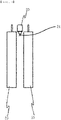
- FIG. 1 is a perspective view illustrating a battery module having a conventional fire extinguisher.
- the battery module is configured such that a fire extinguisher 20 containing a fire-extinguishing material is located between a plurality of battery cells 10 and such that a rupture portion (not shown), which is made of a shape memory alloy and which is formed in the shape of a spring having a pointed end, is provided in an injection portion 21 located at the lower part of the fire extinguisher 20.
- the rupture portion is located so as to be shorter than the height of a clogged part of the injection portion 21.
- the rupture portion is increased in length to form a hole in the injection portion 21 such that the fire-extinguishing material is injected therethrough.
- the rupture portion the shape of which is changed depending on temperature, is surrounded by the injection portion 21 and is spaced apart from the battery cells 10, from which heat is generated, by a predetermined distance, whereby it is difficult to inject the fire-extinguishing material in a timely manner. Furthermore, an additional device and space are necessary to fix the fire extinguisher 20 in the battery module, whereby a manufacturing process is complicated and energy density is low.
- Patent Document 1 Korean Patent Application Publication No. 2019-0041725
- the present invention has been made in view of the above problems, and it is an object of the present invention to provide a battery module having a fire-extinguishing unit including a fire-extinguishing material capable of sensitively responding to change in heat of the battery module to secure safety, whereby it is possible to reduce a secondary accident rate.
- a battery module includes a plurality of battery cells (100) stacked in a vertical direction or a horizontal direction and a fire-extinguishing unit (200) located adjacent to each of the battery cells (100), wherein the fire-extinguishing unit (200) includes a fire-extinguishing pack (210) containing a fire-extinguishing material and at least one breaking unit (220) interposed between the battery cell (100) and the fire-extinguishing pack (210).
- the fire-extinguishing pack (210) may be in tight contact with one surface or opposite surfaces of the battery cell (100).
- the breaking unit (220) may be a coupling portion (221) fixed to the battery cell (100) or the fire-extinguishing pack (210) and a blade portion (222) extending from the coupling portion (221), and the blade portion (222) may be made of a shape memory alloy.
- the blade portion (222) when the temperature of the battery cell (100) increases to a predetermined temperature or higher, the blade portion (222) may be deformed by a predetermined angle to rupture the fire-extinguishing pack (210).
- the breaking unit (220) may be located adjacent to an electrode lead (110) of the battery cell (100) .
- the blade portion (222) may be provided along the edge of the coupling portion (221) in plural.
- the blade portion (222) may extend so as to have a thickness equal to the thickness of the coupling portion (221).
- the blade portion (222) may have a thickness gradually decreasing with increasing distance from the edge of the coupling portion (221).
- a recessed portion (223) may be formed in the portion at which the blade portion (222) and the coupling portion (221) are connected to each other.
- a battery pack according to the present invention includes the battery module.
- a battery module having a fire-extinguishing unit including a fire-extinguishing material according to the present invention has an advantage in that a breaking unit made of a shape memory alloy, which is deformed at a predetermined temperature or higher, is located in tight contact with a battery cell, whereby it is possible to extinguish fire without recognition through a separate sensing device, and therefore it is possible to prevent non-operation due to systemic errors.
- the battery module according to the present invention has an advantage in that a sensing device configured to sense temperature or voltage of the battery module and a separate device configured to fix the breaking unit are not necessary, whereby a manufacturing process is simple and energy density is improved.
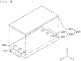
- FIG. 2 is a perspective view and a side front view of a battery module according to a first preferred embodiment of the present invention
- FIG. 3 is an exploded perspective view of a battery cell and a fire-extinguishing unit according to a first preferred embodiment of the present invention.
- the battery module having the fire-extinguishing unit according to the present invention includes a plurality of battery cells 100 and a fire-extinguishing unit 200.
- the plurality of battery cells 100 may be stacked side by side in a vertical direction or in a horizontal direction with respect to the ground and may be connected to each other in series and in parallel.
- each of the battery cells 100 is a pouch-shaped battery cell including a cell assembly (not shown), a cell case, and a pair of electrode leads 110.
- the cell assembly may be a jellyroll type cell assembly, which is configured to have a structure in which a long sheet type positive electrode and a long sheet type negative electrode are wound in the state in which a separator is interposed therebetween, a stacked type cell assembly including unit cells, each of which is configured to have a structure in which a rectangular positive electrode and a rectangular negative electrode are stacked in the state in which a separator is interposed therebetween, a stacked and folded type cell assembly, which is configured to have a structure in which unit cells are wound using a long separation film, or a laminated and stacked type cell assembly, which is configured to have a structure in which unit cells are stacked in the state in which a separator is interposed therebetween and are then attached to each other.
- the present invention is not limited thereto.
- the cell assembly is mounted in the cell case.
- the cell case is generally configured to have a laminate sheet structure including an inner layer, a metal layer, and an outer layer.
- the inner layer is disposed in direct contact with the cell assembly, and therefore the inner layer must exhibit high insulation properties and high resistance to an electrolytic solution.
- the inner layer must exhibit high sealability in order to hermetically seal the cell case from the outside, i.e. a thermally-bonded sealed portion between inner layers must exhibit excellent thermal bonding strength.
- the inner layer may be made of a material selected from among a polyolefin-based resin, such as polypropylene, polyethylene, polyethylene acrylate, or polybutylene, a polyurethane resin, and a polyimide resin, which exhibit excellent chemical resistance and high sealability.
- polypropylene which exhibits excellent mechanical-physical properties, such as tensile strength, rigidity, surface hardness, and resistance to impact strength, and excellent chemical resistance, is the most preferably used.
- the metal layer which is disposed so as to abut the inner layer, corresponds to a barrier layer configured to prevent moisture or various kinds of gas from permeating into the battery from the outside.
- Aluminum film which is light and easily shapeable, may be used as a preferred material for the metal layer.
- the outer layer is provided on the other surface of the metal layer.
- the outer layer may be made of a heat-resistant polymer that exhibits excellent tensile strength, resistance to moisture permeation, and resistance to air transmission such that the outer layer exhibits high heat resistance and chemical resistance while protecting the electrode assembly.
- the outer layer may be made of nylon or polyethylene terephthalate.
- the present invention is not limited thereto.
- the pair of electrode leads 110 includes a positive electrode lead and a negative electrode lead.
- the positive electrode lead and the negative electrode lead may be exposed outwards from the cell case in the state in which positive electrode tabs and negative electrode tabs of the cell assembly are electrically connected to the positive electrode lead and the negative electrode lead, respectively, or the positive electrode lead and the negative electrode lead may be directly connected to the cell assembly without electrode tabs.
- the battery cells correspond to commonly known constructions, and therefore a more detailed description thereof will be omitted.
- the fire-extinguishing unit 200 includes a fire-extinguishing pack 210 and a breaking unit 220.
- the fire-extinguishing pack 210 may have defined therein a space configured to receive a fire-extinguishing material, and may be made of at least one of a polyolefin-based resin, such as polypropylene, polyethylene, polyethylene acrylate, or polybutylene, polytetrafluoroethylene, a polyurethane resin, and a polyimide resin, each of which has a predetermined thickness that can be torn by the breaking unit 220.
- a polyolefin-based resin such as polypropylene, polyethylene, polyethylene acrylate, or polybutylene, polytetrafluoroethylene, a polyurethane resin, and a polyimide resin, each of which has a predetermined thickness that can be torn by the breaking unit 220.
- the fire-extinguishing pack 210 may be located at one surface or opposite surfaces of each of the battery cells 100, and may be prismatic, which is similar to the outer shape of the battery cell 100. However, the fire-extinguishing pack 210 may be amorphous, whereby the shape of the fire-extinguishing pack may be freely changed.
- a fire-extinguishing material configured to inhibit an increase in temperature of the battery cells 100 to a predetermined temperature or higher or flames generated by outbreak of fire is contained in the fire-extinguishing pack 210.
- At least one of inorganic carbonate, inorganic phosphate, inorganic sulfate, sodium bicarbonate, potassium bicarbonate, and ammonium phosphate monobasic may be used as an example of the fire-extinguishing material.
- the fire-extinguishing material is not particularly restricted as long as the fire-extinguishing material is a material having a fire-extinguishing function.
- the fire-extinguishing material it is more preferable for the fire-extinguishing material to be liquid such that the fire-extinguishing material can be rapidly discharged, although the fire-extinguishing material may be powder.
- the breaking unit 220 includes a coupling portion 221 fixed to a predetermined part of the battery cell 100 or the fire-extinguishing pack 210 and a blade portion 222 extending from the edge of one side of the coupling portion 221.
- the coupling portion 221 is fixed to the battery cell 100 or the fire-extinguishing pack 210 in order to prevent movement of the breaking unit 220.
- the blade portion 222 tears or breaks the fire-extinguishing pack 210 in order to discharge the fire-extinguishing material contained therein.
- the blade portion 222 it is preferable for the blade portion 222 to be configured such that the width of the blade portion (Y-axis direction) gradually decreases with increasing distance from the coupling portion 221 so as to have a pointed shape.
- the breaking unit 220 is made of a shape memory alloy such that the shape of the blade portion 222 is changed by a predetermined temperature or higher, which will be described below in more detail.
- the position of the breaking unit 220 is not particularly restricted as long as the breaking unit 220 comes into tight contact with the fire-extinguishing pack 210.
- the breaking unit 220 is located in the vicinity of each of the electrode leads 110. More preferably, two or more breaking units 220 are provided. The reason for this is that, when heat is generated from the battery cell 100 due to overcharging, a larger amount of heat is generated in the vicinity of each of the electrode leads 110, and therefore it is possible to more rapidly discharge the fire-extinguishing material in the case in which two or more breaking units 220 are provided in the vicinity of each of the electrode leads 110.
- FIG. 4 is a view illustrating change of the fire-extinguishing unit based on temperature in the battery cell according to the first preferred embodiment of the present invention.
- the shape of the breaking unit 220 is changed when the breaking unit is heated to a predetermined temperature or higher, since the breaking unit is made of a shape memory alloy, the shape of which is changed depending on temperature, as previously described.
- the coupling portion 221 and the blade portion 222 are simply disposed in tight contact between the battery cell 100 and the fire-extinguishing pack 210.
- heat is transferred to the breaking unit 220, whereby the blade portion 222 rises by a predetermined angle, i.e. the shape of the blade portion is changed.
- a portion of the fire-extinguishing pack 210 ruptures as the result of deformation of the blade portion 222.
- the fire-extinguishing material contained in the fire-extinguishing pack is ejected to control overheating or fire of the battery cell 100.
- the breaking unit 220 is a thin flat plate that is located between the battery cell 100 and the fire-extinguishing pack 210 and that is made of a shape memory alloy, which is deformed depending on temperature, as described above, a space occupied by the breaking unit is small, unlike a sensing device configured to sense temperature and voltage, whereby space utilization is improved, and therefore it is possible to improve energy density of the battery module.
- the shape memory alloy of which the breaking unit 220 is made, may include at least one of a nickel-titanium (Ni-Ti) alloy, a copper-zinc (Cu-Zn) alloy, a copper-zinc-aluminum (Cu-Zn-Al) alloy, a copper-cadmium (Cu-Cd) alloy, a nickel-aluminum (Ni-Al) alloy, a copper-zinc-aluminum (Cu-Zn-Al) alloy, and a copper-aluminum-nickel (Cu-Al-Ni) alloy, the shape of each of which is changed due to crystal structure change when heated to a predetermined temperature or higher.
- Ni-Ti nickel-titanium
- Cu-Zn copper-zinc
- Cu-Zn-Al copper-zinc-aluminum
- Cu-Cd copper-cadmium
- Ni-Al nickel-aluminum
- Cu-Zn-Al copper-zinc-alumin
- the fire-extinguishing pack 210 is located at one side or opposite sides of the battery cell 100 and the breaking unit 220, which is made of a shape memory alloy, is located between the battery cell 100 and the fire-extinguishing pack 210, as described above, the fire-extinguishing material is discharged from the fire-extinguishing pack 210 when the temperature of the battery cell 100 abnormally increases, whereby it is possible to rapidly inhibit outbreak of fire.
- no complicated sensing device or no installation space is necessary, and therefore it is possible to simplify a manufacturing process and to improve energy density.
- FIG. 5 is a plan view illustrating breaking units according to second and third preferred embodiments of the present invention.
- FIG. 5 (a) of FIG. 5 is a plan view of the breaking unit 220 according to the second preferred embodiment of the present invention, wherein four blade portions 222 are formed along the edge of a quadrangular coupling portion 221.
- the breaking unit 220 when thermal runaway occurs in the battery cell 100 due to overcharging, the four blade portions 222 rise by a predetermined angle to rupture a portion of the fire-extinguishing pack 220. Consequently, it is possible to induce rapid discharge of the fire-extinguishing material while reducing the installation number of the breaking unit 220.
- the breaking unit 220 when thermal runaway occurs in the battery cell 100 due to overcharging, the two blade portions 222 rise by a predetermined angle to rupture a portion of the fire-extinguishing pack 220. Consequently, it is possible to induce rapid discharge of the fire-extinguishing material while reducing the installation number of the breaking unit.
- blade portions 222 according to the third embodiment may be provided at one side of the quadrangular coupling portion 221 according to the second embodiment, the shape of the coupling portion 221 may be polygonal, for example triangular, pentagonal, hexagonal, or octagonal, or circular, and three or more blade portions 222 may be formed at the edge of one side of the coupling portion.
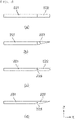
- FIG. 6 is a sectional view illustrating breaking units according to preferred modifications of the present invention.
- the breaking unit 220 may be configured such that a coupling portion 221 and a blade portion 222 extend so as to have the same thickness, as shown in (a) of FIG. 6 . In this case, it is possible to easily manufacture the breaking unit.
- the breaking unit 220 shown in (b) of FIG. 6 is configured such that a blade portion 222 extending from a flat coupling portion 221 has a thickness gradually decreasing with increasing distance from the edge of the coupling portion 221, specifically the blade portion has a triangular shape somewhat spaced apart from one side of the battery cell 100.
- the tip end of the blade portion 222 is very sharp, whereby it is possible to easily rupture the fire-extinguishing pack 210.
- the breaking unit 220 shown in (c) of FIG. 6 is configured such that a coupling portion 221 and a blade portion 222 extend so as to have the same thickness, in the same manner as shown in (a) of FIG. 6 , and a recessed portion 223 having a predetermined depth is further formed in the portion at which the coupling portion 221 and the blade portion 222 are connected to each other.
- the blade portion 222 may be more sensitively deformed.
- the breaking unit 220 shown in (d) of FIG. 6 is configured such that a blade portion 222 extending from a flat coupling portion 221 has a thickness gradually decreasing with increasing distance from the edge of the coupling portion 221, in the same manner as shown in (b) of FIG. 6 , and a recessed portion 223 having a predetermined depth is formed in the portion at which the coupling portion 221 and the blade portion 222 are connected to each other. Consequently, the blade portion 222 may be easily deformed, as described with reference to (c) of FIG. 6 .
- the recessed portion 223 is shown as being provided at only one side of the coupling portion in the figures, one recessed portion may be provided at each of opposite sides of the coupling portion.
Landscapes
- Chemical & Material Sciences (AREA)
- General Chemical & Material Sciences (AREA)
- Electrochemistry (AREA)
- Chemical Kinetics & Catalysis (AREA)
- Business, Economics & Management (AREA)
- Public Health (AREA)
- Emergency Management (AREA)
- Health & Medical Sciences (AREA)
- Engineering & Computer Science (AREA)
- Life Sciences & Earth Sciences (AREA)
- Manufacturing & Machinery (AREA)
- Mechanical Engineering (AREA)
- Forests & Forestry (AREA)
- Battery Mounting, Suspending (AREA)
Applications Claiming Priority (2)
| Application Number | Priority Date | Filing Date | Title |
|---|---|---|---|
| KR1020200053494A KR102818246B1 (ko) | 2020-05-04 | 2020-05-04 | 소화물질을 포함하는 소화부가 구비된 전지 모듈 |
| PCT/KR2020/015839 WO2021225237A1 (ko) | 2020-05-04 | 2020-11-12 | 소화물질을 포함하는 소화부가 구비된 전지 모듈 |
Publications (3)
| Publication Number | Publication Date |
|---|---|
| EP4071902A1 true EP4071902A1 (de) | 2022-10-12 |
| EP4071902A4 EP4071902A4 (de) | 2024-08-21 |
| EP4071902B1 EP4071902B1 (de) | 2025-10-08 |
Family
ID=78468024
Family Applications (1)
| Application Number | Title | Priority Date | Filing Date |
|---|---|---|---|
| EP20934601.4A Active EP4071902B1 (de) | 2020-05-04 | 2020-11-12 | Batteriemodul mit feuerlöscheinheit mit feuerlöschendem material |
Country Status (8)
| Country | Link |
|---|---|
| US (1) | US20230109116A1 (de) |
| EP (1) | EP4071902B1 (de) |
| JP (1) | JP7434584B2 (de) |
| KR (1) | KR102818246B1 (de) |
| CN (1) | CN114982050B (de) |
| ES (1) | ES3051365T3 (de) |
| PL (1) | PL4071902T3 (de) |
| WO (1) | WO2021225237A1 (de) |
Families Citing this family (6)
| Publication number | Priority date | Publication date | Assignee | Title |
|---|---|---|---|---|
| KR20230076463A (ko) * | 2021-11-24 | 2023-05-31 | 주식회사 엘지에너지솔루션 | 전해액 추가 주액이 가능한 리튬 이차전지 |
| KR20230141116A (ko) * | 2022-03-31 | 2023-10-10 | 주식회사 엘지에너지솔루션 | 전지 케이스 및 이차 전지 |
| JP7364019B1 (ja) | 2022-04-26 | 2023-10-18 | 栗田工業株式会社 | 蓄電デバイス構造体 |
| KR20230171266A (ko) * | 2022-06-13 | 2023-12-20 | 에스케이온 주식회사 | 소화 장치를 포함하는 파우치형 이차전지 |
| US20260031436A1 (en) * | 2022-09-01 | 2026-01-29 | Lg Energy Solution, Ltd. | Secondary Battery and Device Including the Same |
| US20240097236A1 (en) * | 2022-09-21 | 2024-03-21 | Viridi Parente, Inc. | Stacking frame and cooling system for battery cells |
Family Cites Families (18)
| Publication number | Priority date | Publication date | Assignee | Title |
|---|---|---|---|---|
| US6293020B1 (en) * | 1997-02-14 | 2001-09-25 | Nitinol Technologies, Inc. | Cutting instruments |
| US20100331883A1 (en) * | 2004-10-15 | 2010-12-30 | Schmitz Gregory P | Access and tissue modification systems and methods |
| JP5181743B2 (ja) * | 2008-03-11 | 2013-04-10 | パナソニック株式会社 | 電力供給機器とそれを用いた電子機器 |
| JP2010097836A (ja) * | 2008-10-17 | 2010-04-30 | Panasonic Corp | 電池パック、それを電源として用いた電子機器、及び電池パック用ケース |
| JP4900534B2 (ja) * | 2009-02-24 | 2012-03-21 | パナソニック株式会社 | 電池モジュールとそれを用いた電池モジュール集合体 |
| DE102011075318A1 (de) * | 2011-05-05 | 2012-11-08 | Sb Limotive Company Ltd. | Batteriegehäuse für Lithium-Ionen-Zellen |
| JP5760713B2 (ja) * | 2011-06-03 | 2015-08-12 | トヨタ自動車株式会社 | 電池パック |
| JP2013004294A (ja) * | 2011-06-16 | 2013-01-07 | Nissan Motor Co Ltd | 組電池 |
| JP2015162285A (ja) * | 2014-02-26 | 2015-09-07 | 日産自動車株式会社 | 電池モジュール |
| KR102010012B1 (ko) * | 2015-11-26 | 2019-08-12 | 주식회사 엘지화학 | 소화 장치가 포함된 배터리 팩 및 이를 이용한 제어 방법 |
| CN205488409U (zh) * | 2016-01-27 | 2016-08-17 | 清华大学 | 电池内短路测试装置 |
| CN106992327B (zh) * | 2016-12-30 | 2019-03-26 | 比亚迪股份有限公司 | 用于电池的形变组件、电池、电池组及车辆 |
| KR102203248B1 (ko) * | 2017-04-07 | 2021-01-13 | 주식회사 엘지화학 | 배터리 모듈 및 이를 포함하는 배터리 팩 |
| KR102561195B1 (ko) * | 2017-08-17 | 2023-07-28 | 에스케이온 주식회사 | 이차전지용 전극리드 및 이를 포함하는 안전성이 향상된 이차전지 |
| CN111093975B (zh) | 2017-09-15 | 2022-03-01 | Jsr株式会社 | 高频电路用层叠体及其制造方法、其用途、以及b阶片 |
| CN207474524U (zh) * | 2017-09-29 | 2018-06-08 | 郑州宇通客车股份有限公司 | 一种车辆及其电池箱、电池模组、灭火部件、灭火容器 |
| KR102446772B1 (ko) * | 2017-10-13 | 2022-09-22 | 에스케이온 주식회사 | 안전 장치를 구비한 전지 모듈 |
| KR102445835B1 (ko) | 2017-10-13 | 2022-09-20 | 에스케이온 주식회사 | 소화 장치를 구비한 전지 모듈 |
-
2020
- 2020-05-04 KR KR1020200053494A patent/KR102818246B1/ko active Active
- 2020-11-12 CN CN202080093899.XA patent/CN114982050B/zh active Active
- 2020-11-12 JP JP2022546533A patent/JP7434584B2/ja active Active
- 2020-11-12 WO PCT/KR2020/015839 patent/WO2021225237A1/ko not_active Ceased
- 2020-11-12 ES ES20934601T patent/ES3051365T3/es active Active
- 2020-11-12 PL PL20934601.4T patent/PL4071902T3/pl unknown
- 2020-11-12 EP EP20934601.4A patent/EP4071902B1/de active Active
- 2020-11-12 US US17/794,551 patent/US20230109116A1/en active Pending
Also Published As
| Publication number | Publication date |
|---|---|
| JP7434584B2 (ja) | 2024-02-20 |
| EP4071902B1 (de) | 2025-10-08 |
| WO2021225237A1 (ko) | 2021-11-11 |
| JP2023513069A (ja) | 2023-03-30 |
| ES3051365T3 (en) | 2025-12-26 |
| KR102818246B1 (ko) | 2025-06-10 |
| PL4071902T3 (pl) | 2025-12-22 |
| CN114982050A (zh) | 2022-08-30 |
| EP4071902A4 (de) | 2024-08-21 |
| US20230109116A1 (en) | 2023-04-06 |
| CN114982050B (zh) | 2024-10-25 |
| KR20210135140A (ko) | 2021-11-12 |
Similar Documents
| Publication | Publication Date | Title |
|---|---|---|
| EP4071902B1 (de) | Batteriemodul mit feuerlöscheinheit mit feuerlöschendem material | |
| EP4060799B1 (de) | Batteriemodul mit einer feuerlöscheinheit | |
| CN115398720B (zh) | 电池的箱体、电池、用电装置、制备电池的方法和装置 | |
| EP3671898B1 (de) | Beutelartige sekundärbatterie mit gasentladungsmitteln | |
| CN113013503B (zh) | 电池及用电装置 | |
| EP3644403A1 (de) | Batteriemodul mit gasentladungsstruktur | |
| JP7549733B2 (ja) | 電池、受電装置、電池を作製する方法及び設備 | |
| EP3540818B1 (de) | Batteriemodul sowie batteriepack und fahrzeug damit | |
| WO2022109884A1 (zh) | 电池单体及其制造方法和系统、电池以及用电装置 | |
| US20230223650A1 (en) | Battery, electric apparatus, and method and apparatus for preparing battery | |
| JP7673999B2 (ja) | 二次電池およびその製造方法 | |
| JP7536385B2 (ja) | 火災遷移防止構造が備えられた電池モジュール及びこれを含む電池パック | |
| EP3540823A1 (de) | Batteriemodul sowie batteriepack und fahrzeug damit | |
| EP4322289A1 (de) | Batteriemodul mit erhöhter sicherheit | |
| JP2023524705A (ja) | スウェリングの際に噴出するフレア及びスパークを捕集することができるポケットを備えた電池モジュール | |
| EP4142040A1 (de) | Sekundärbatterie und vorrichtung damit | |
| RU2831808C2 (ru) | Аккумуляторная батарея, электрическое устройство, а также способ и оборудование для изготовления аккумуляторной батареи | |
| JP7536390B2 (ja) | 熱的安全性が向上したパウチ型電池セル | |
| EP4576379A1 (de) | Batteriemodul | |
| CN121079839A (zh) | 电池模块、以及包括该电池模块的电池组和车辆 | |
| KR20220161055A (ko) | 이차 전지 및 이를 포함하는 전지 모듈 |
Legal Events
| Date | Code | Title | Description |
|---|---|---|---|
| STAA | Information on the status of an ep patent application or granted ep patent |
Free format text: STATUS: THE INTERNATIONAL PUBLICATION HAS BEEN MADE |
|
| PUAI | Public reference made under article 153(3) epc to a published international application that has entered the european phase |
Free format text: ORIGINAL CODE: 0009012 |
|
| STAA | Information on the status of an ep patent application or granted ep patent |
Free format text: STATUS: REQUEST FOR EXAMINATION WAS MADE |
|
| 17P | Request for examination filed |
Effective date: 20220707 |
|
| AK | Designated contracting states |
Kind code of ref document: A1 Designated state(s): AL AT BE BG CH CY CZ DE DK EE ES FI FR GB GR HR HU IE IS IT LI LT LU LV MC MK MT NL NO PL PT RO RS SE SI SK SM TR |
|
| DAV | Request for validation of the european patent (deleted) | ||
| DAX | Request for extension of the european patent (deleted) | ||
| A4 | Supplementary search report drawn up and despatched |
Effective date: 20240722 |
|
| RIC1 | Information provided on ipc code assigned before grant |
Ipc: B26D 1/00 20060101ALI20240716BHEP Ipc: A62C 35/10 20060101ALI20240716BHEP Ipc: A62C 37/16 20060101ALI20240716BHEP Ipc: A62C 3/16 20060101ALI20240716BHEP Ipc: H01M 10/42 20060101ALI20240716BHEP Ipc: H01M 50/20 20210101AFI20240716BHEP |
|
| STAA | Information on the status of an ep patent application or granted ep patent |
Free format text: STATUS: EXAMINATION IS IN PROGRESS |
|
| 17Q | First examination report despatched |
Effective date: 20250114 |
|
| GRAP | Despatch of communication of intention to grant a patent |
Free format text: ORIGINAL CODE: EPIDOSNIGR1 |
|
| STAA | Information on the status of an ep patent application or granted ep patent |
Free format text: STATUS: GRANT OF PATENT IS INTENDED |
|
| INTG | Intention to grant announced |
Effective date: 20250507 |
|
| P01 | Opt-out of the competence of the unified patent court (upc) registered |
Free format text: CASE NUMBER: APP_26038/2025 Effective date: 20250602 |
|
| GRAS | Grant fee paid |
Free format text: ORIGINAL CODE: EPIDOSNIGR3 |
|
| GRAA | (expected) grant |
Free format text: ORIGINAL CODE: 0009210 |
|
| STAA | Information on the status of an ep patent application or granted ep patent |
Free format text: STATUS: THE PATENT HAS BEEN GRANTED |
|
| AK | Designated contracting states |
Kind code of ref document: B1 Designated state(s): AL AT BE BG CH CY CZ DE DK EE ES FI FR GB GR HR HU IE IS IT LI LT LU LV MC MK MT NL NO PL PT RO RS SE SI SK SM TR |
|
| REG | Reference to a national code |
Ref country code: GB Ref legal event code: FG4D Ref country code: CH Ref legal event code: F10 Free format text: ST27 STATUS EVENT CODE: U-0-0-F10-F00 (AS PROVIDED BY THE NATIONAL OFFICE) Effective date: 20251008 |
|
| REG | Reference to a national code |
Ref country code: DE Ref legal event code: R096 Ref document number: 602020060327 Country of ref document: DE |
|
| REG | Reference to a national code |
Ref country code: IE Ref legal event code: FG4D |
|
| REG | Reference to a national code |
Ref country code: SE Ref legal event code: TRGR |
|
| REG | Reference to a national code |
Ref country code: ES Ref legal event code: FG2A Ref document number: 3051365 Country of ref document: ES Kind code of ref document: T3 Effective date: 20251226 |
|
| PGFP | Annual fee paid to national office [announced via postgrant information from national office to epo] |
Ref country code: DE Payment date: 20251020 Year of fee payment: 6 |
|
| PGFP | Annual fee paid to national office [announced via postgrant information from national office to epo] |
Ref country code: GB Payment date: 20251023 Year of fee payment: 6 |
|
| PGFP | Annual fee paid to national office [announced via postgrant information from national office to epo] |
Ref country code: FR Payment date: 20251021 Year of fee payment: 6 Ref country code: HU Payment date: 20251216 Year of fee payment: 6 |
|
| PGFP | Annual fee paid to national office [announced via postgrant information from national office to epo] |
Ref country code: BE Payment date: 20251020 Year of fee payment: 6 |
|
| PGFP | Annual fee paid to national office [announced via postgrant information from national office to epo] |
Ref country code: SE Payment date: 20251021 Year of fee payment: 6 |
|
| PGFP | Annual fee paid to national office [announced via postgrant information from national office to epo] |
Ref country code: PL Payment date: 20251020 Year of fee payment: 6 |
|
| PGFP | Annual fee paid to national office [announced via postgrant information from national office to epo] |
Ref country code: ES Payment date: 20251215 Year of fee payment: 6 |