EP3671898B1 - Beutelartige sekundärbatterie mit gasentladungsmitteln - Google Patents
Beutelartige sekundärbatterie mit gasentladungsmitteln Download PDFInfo
- Publication number
- EP3671898B1 EP3671898B1 EP19792234.7A EP19792234A EP3671898B1 EP 3671898 B1 EP3671898 B1 EP 3671898B1 EP 19792234 A EP19792234 A EP 19792234A EP 3671898 B1 EP3671898 B1 EP 3671898B1
- Authority
- EP
- European Patent Office
- Prior art keywords
- pouch
- secondary battery
- type
- type case
- gas
- Prior art date
- Legal status (The legal status is an assumption and is not a legal conclusion. Google has not performed a legal analysis and makes no representation as to the accuracy of the status listed.)
- Active
Links
Images


Classifications
-
- H—ELECTRICITY
- H01—ELECTRIC ELEMENTS
- H01M—PROCESSES OR MEANS, e.g. BATTERIES, FOR THE DIRECT CONVERSION OF CHEMICAL ENERGY INTO ELECTRICAL ENERGY
- H01M50/00—Constructional details or processes of manufacture of the non-active parts of electrochemical cells other than fuel cells, e.g. hybrid cells
- H01M50/10—Primary casings; Jackets or wrappings
- H01M50/102—Primary casings; Jackets or wrappings characterised by their shape or physical structure
- H01M50/105—Pouches or flexible bags
-
- H—ELECTRICITY
- H01—ELECTRIC ELEMENTS
- H01M—PROCESSES OR MEANS, e.g. BATTERIES, FOR THE DIRECT CONVERSION OF CHEMICAL ENERGY INTO ELECTRICAL ENERGY
- H01M50/00—Constructional details or processes of manufacture of the non-active parts of electrochemical cells other than fuel cells, e.g. hybrid cells
- H01M50/10—Primary casings; Jackets or wrappings
- H01M50/172—Arrangements of electric connectors penetrating the casing
- H01M50/174—Arrangements of electric connectors penetrating the casing adapted for the shape of the cells
- H01M50/178—Arrangements of electric connectors penetrating the casing adapted for the shape of the cells for pouch or flexible bag cells
-
- H—ELECTRICITY
- H01—ELECTRIC ELEMENTS
- H01M—PROCESSES OR MEANS, e.g. BATTERIES, FOR THE DIRECT CONVERSION OF CHEMICAL ENERGY INTO ELECTRICAL ENERGY
- H01M50/00—Constructional details or processes of manufacture of the non-active parts of electrochemical cells other than fuel cells, e.g. hybrid cells
- H01M50/20—Mountings; Secondary casings or frames; Racks, modules or packs; Suspension devices; Shock absorbers; Transport or carrying devices; Holders
-
- H—ELECTRICITY
- H01—ELECTRIC ELEMENTS
- H01M—PROCESSES OR MEANS, e.g. BATTERIES, FOR THE DIRECT CONVERSION OF CHEMICAL ENERGY INTO ELECTRICAL ENERGY
- H01M50/00—Constructional details or processes of manufacture of the non-active parts of electrochemical cells other than fuel cells, e.g. hybrid cells
- H01M50/30—Arrangements for facilitating escape of gases
- H01M50/317—Re-sealable arrangements
- H01M50/325—Re-sealable arrangements comprising deformable valve members, e.g. elastic or flexible valve members
- H01M50/333—Spring-loaded vent valves
-
- H—ELECTRICITY
- H01—ELECTRIC ELEMENTS
- H01M—PROCESSES OR MEANS, e.g. BATTERIES, FOR THE DIRECT CONVERSION OF CHEMICAL ENERGY INTO ELECTRICAL ENERGY
- H01M50/00—Constructional details or processes of manufacture of the non-active parts of electrochemical cells other than fuel cells, e.g. hybrid cells
- H01M50/30—Arrangements for facilitating escape of gases
- H01M50/342—Non-re-sealable arrangements
-
- H—ELECTRICITY
- H01—ELECTRIC ELEMENTS
- H01M—PROCESSES OR MEANS, e.g. BATTERIES, FOR THE DIRECT CONVERSION OF CHEMICAL ENERGY INTO ELECTRICAL ENERGY
- H01M50/00—Constructional details or processes of manufacture of the non-active parts of electrochemical cells other than fuel cells, e.g. hybrid cells
- H01M50/30—Arrangements for facilitating escape of gases
- H01M50/35—Gas exhaust passages comprising elongated, tortuous or labyrinth-shaped exhaust passages
-
- H—ELECTRICITY
- H01—ELECTRIC ELEMENTS
- H01M—PROCESSES OR MEANS, e.g. BATTERIES, FOR THE DIRECT CONVERSION OF CHEMICAL ENERGY INTO ELECTRICAL ENERGY
- H01M50/00—Constructional details or processes of manufacture of the non-active parts of electrochemical cells other than fuel cells, e.g. hybrid cells
- H01M50/40—Separators; Membranes; Diaphragms; Spacing elements inside cells
- H01M50/46—Separators, membranes or diaphragms characterised by their combination with electrodes
-
- H—ELECTRICITY
- H01—ELECTRIC ELEMENTS
- H01M—PROCESSES OR MEANS, e.g. BATTERIES, FOR THE DIRECT CONVERSION OF CHEMICAL ENERGY INTO ELECTRICAL ENERGY
- H01M50/00—Constructional details or processes of manufacture of the non-active parts of electrochemical cells other than fuel cells, e.g. hybrid cells
- H01M50/50—Current conducting connections for cells or batteries
- H01M50/531—Electrode connections inside a battery casing
-
- H—ELECTRICITY
- H01—ELECTRIC ELEMENTS
- H01M—PROCESSES OR MEANS, e.g. BATTERIES, FOR THE DIRECT CONVERSION OF CHEMICAL ENERGY INTO ELECTRICAL ENERGY
- H01M50/00—Constructional details or processes of manufacture of the non-active parts of electrochemical cells other than fuel cells, e.g. hybrid cells
- H01M50/50—Current conducting connections for cells or batteries
- H01M50/543—Terminals
- H01M50/547—Terminals characterised by the disposition of the terminals on the cells
- H01M50/55—Terminals characterised by the disposition of the terminals on the cells on the same side of the cell
-
- H—ELECTRICITY
- H01—ELECTRIC ELEMENTS
- H01M—PROCESSES OR MEANS, e.g. BATTERIES, FOR THE DIRECT CONVERSION OF CHEMICAL ENERGY INTO ELECTRICAL ENERGY
- H01M50/00—Constructional details or processes of manufacture of the non-active parts of electrochemical cells other than fuel cells, e.g. hybrid cells
- H01M50/50—Current conducting connections for cells or batteries
- H01M50/543—Terminals
- H01M50/552—Terminals characterised by their shape
- H01M50/553—Terminals adapted for prismatic, pouch or rectangular cells
-
- H—ELECTRICITY
- H01—ELECTRIC ELEMENTS
- H01M—PROCESSES OR MEANS, e.g. BATTERIES, FOR THE DIRECT CONVERSION OF CHEMICAL ENERGY INTO ELECTRICAL ENERGY
- H01M50/00—Constructional details or processes of manufacture of the non-active parts of electrochemical cells other than fuel cells, e.g. hybrid cells
- H01M50/50—Current conducting connections for cells or batteries
- H01M50/572—Means for preventing undesired use or discharge
- H01M50/574—Devices or arrangements for the interruption of current
- H01M50/578—Devices or arrangements for the interruption of current in response to pressure
-
- H—ELECTRICITY
- H01—ELECTRIC ELEMENTS
- H01M—PROCESSES OR MEANS, e.g. BATTERIES, FOR THE DIRECT CONVERSION OF CHEMICAL ENERGY INTO ELECTRICAL ENERGY
- H01M50/00—Constructional details or processes of manufacture of the non-active parts of electrochemical cells other than fuel cells, e.g. hybrid cells
- H01M50/50—Current conducting connections for cells or batteries
- H01M50/572—Means for preventing undesired use or discharge
- H01M50/584—Means for preventing undesired use or discharge for preventing incorrect connections inside or outside the batteries
- H01M50/588—Means for preventing undesired use or discharge for preventing incorrect connections inside or outside the batteries outside the batteries, e.g. incorrect connections of terminals or busbars
-
- H—ELECTRICITY
- H01—ELECTRIC ELEMENTS
- H01M—PROCESSES OR MEANS, e.g. BATTERIES, FOR THE DIRECT CONVERSION OF CHEMICAL ENERGY INTO ELECTRICAL ENERGY
- H01M50/00—Constructional details or processes of manufacture of the non-active parts of electrochemical cells other than fuel cells, e.g. hybrid cells
- H01M50/50—Current conducting connections for cells or batteries
- H01M50/572—Means for preventing undesired use or discharge
- H01M50/584—Means for preventing undesired use or discharge for preventing incorrect connections inside or outside the batteries
- H01M50/59—Means for preventing undesired use or discharge for preventing incorrect connections inside or outside the batteries characterised by the protection means
- H01M50/595—Tapes
-
- H—ELECTRICITY
- H01—ELECTRIC ELEMENTS
- H01M—PROCESSES OR MEANS, e.g. BATTERIES, FOR THE DIRECT CONVERSION OF CHEMICAL ENERGY INTO ELECTRICAL ENERGY
- H01M50/00—Constructional details or processes of manufacture of the non-active parts of electrochemical cells other than fuel cells, e.g. hybrid cells
- H01M50/10—Primary casings; Jackets or wrappings
- H01M50/116—Primary casings; Jackets or wrappings characterised by the material
- H01M50/117—Inorganic material
- H01M50/119—Metals
-
- H—ELECTRICITY
- H01—ELECTRIC ELEMENTS
- H01M—PROCESSES OR MEANS, e.g. BATTERIES, FOR THE DIRECT CONVERSION OF CHEMICAL ENERGY INTO ELECTRICAL ENERGY
- H01M50/00—Constructional details or processes of manufacture of the non-active parts of electrochemical cells other than fuel cells, e.g. hybrid cells
- H01M50/10—Primary casings; Jackets or wrappings
- H01M50/116—Primary casings; Jackets or wrappings characterised by the material
- H01M50/121—Organic material
-
- H—ELECTRICITY
- H01—ELECTRIC ELEMENTS
- H01M—PROCESSES OR MEANS, e.g. BATTERIES, FOR THE DIRECT CONVERSION OF CHEMICAL ENERGY INTO ELECTRICAL ENERGY
- H01M50/00—Constructional details or processes of manufacture of the non-active parts of electrochemical cells other than fuel cells, e.g. hybrid cells
- H01M50/10—Primary casings; Jackets or wrappings
- H01M50/116—Primary casings; Jackets or wrappings characterised by the material
- H01M50/124—Primary casings; Jackets or wrappings characterised by the material having a layered structure
- H01M50/126—Primary casings; Jackets or wrappings characterised by the material having a layered structure comprising three or more layers
- H01M50/129—Primary casings; Jackets or wrappings characterised by the material having a layered structure comprising three or more layers with two or more layers of only organic material
-
- Y—GENERAL TAGGING OF NEW TECHNOLOGICAL DEVELOPMENTS; GENERAL TAGGING OF CROSS-SECTIONAL TECHNOLOGIES SPANNING OVER SEVERAL SECTIONS OF THE IPC; TECHNICAL SUBJECTS COVERED BY FORMER USPC CROSS-REFERENCE ART COLLECTIONS [XRACs] AND DIGESTS
- Y02—TECHNOLOGIES OR APPLICATIONS FOR MITIGATION OR ADAPTATION AGAINST CLIMATE CHANGE
- Y02E—REDUCTION OF GREENHOUSE GAS [GHG] EMISSIONS, RELATED TO ENERGY GENERATION, TRANSMISSION OR DISTRIBUTION
- Y02E60/00—Enabling technologies; Technologies with a potential or indirect contribution to GHG emissions mitigation
- Y02E60/10—Energy storage using batteries
Definitions
- the present invention relates to a pouch-type secondary battery, and more particularly to a pouch-type secondary battery having a gas discharge means, wherein the gas discharge means is provided between a pair of insulative films, the gas discharge means being configured to discharge gas, whereby the swelling phenomenon and explosion of the battery are prevented.
- secondary batteries which are capable of being charged and discharged, have been used as energy sources for various mobile devices.
- secondary batteries have also attracted considerable attention as energy sources for electric vehicles and hybrid electric vehicles, which have been presented as alternatives to existing gasoline and diesel vehicles using fossil fuels.
- secondary batteries are classified into a cylindrical battery having an electrode assembly mounted in a cylindrical metal can, a prismatic battery having an electrode assembly mounted in a prismatic metal can, and a pouch-type battery having an electrode assembly mounted in a pouch-type case made of an aluminum laminate sheet.
- the electrode assembly which is mounted in the battery case, is a power generating element that is configured to have a structure including a positive electrode, a negative electrode, and a separator that is interposed between the positive electrode and the negative electrode and that can be charged and discharged.
- the electrode assembly is classified as a jelly-roll type electrode assembly, which is configured to have a structure in which a long sheet type positive electrode and a long sheet type negative electrode, to which active materials are applied, are wound in the state in which a separator is disposed between the positive electrode and the negative electrode, or a stacked type electrode assembly, which is configured to have a structure in which a plurality of positive electrodes having a predetermined size and a plurality of negative electrodes having a predetermined size are sequentially stacked in the state in which separators are disposed respectively between the positive electrodes and the negative electrodes.
- the jelly-roll type electrode assembly has advantages in that it is easy to manufacture the jelly-roll type electrode assembly and in that the jelly-roll type electrode assembly has high energy density per unit weight.
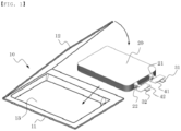
- such a secondary battery is configured to have a structure in which an electrode assembly 20 is mounted in a pouch-type battery case 10 and in which positive and negative electrode tabs 21 and 22 are welded respectively to two electrode leads 31 and 32, which are exposed out of the battery case 10.
- the edge of the case is sealed in the state in which a pair of insulative films 41 is attached to the upper surface and the lower surface of the electrode lead 31 and a pair of insulative films 42 is attached to the upper surface and the lower surface of the electrode lead 32.
- a secondary battery is charged and discharged through a process in which lithium ions from a lithium metal oxide of a positive electrode are repeatedly intercalated into a negative electrode, such as a graphite electrode, and the lithium ions are repeatedly deintercalated from the negative electrode.
- heat may be generated from such a secondary battery in the event of a short circuit in the secondary battery due to an external impact, overcharge of the secondary battery, or overdischarge of the secondary battery.
- an electrolyte may be decomposed in the secondary battery, and thermal runaway may occur in the secondary battery. That is, the safety of the secondary battery is compromised in several aspects.
- the electrolyte and an electrode active material electrochemically react with each other, and the explosion of the battery due to gas generated as the result of this electrochemical reaction has been noted as a very serious problem.
- Korean Patent Application Publication No. 2013-0048419 discloses a pouch-type secondary battery including an electrode assembly, a pouch-type case configured to receive the electrode assembly, upper and lower laminate sheets constituting the pouch-type case, a sealed portion formed by thermally fusing the upper and lower laminate sheets, positive and negative electrode tabs exposed from the sealed portion, and a safety vent having an alloy inserted between the upper and lower laminate sheet constituting the sealed portion, the alloy having a lower melting point than the sealed portion, the alloy being configured to melt at a predetermined temperature.
- This conventional art has an advantage in that, when the temperature of the secondary battery reaches a reference level, the safety vent is opened, whereby it is possible to prevent the battery from catching fire or exploding.
- Patent Document 0001 Korean Patent Application Publication No. 2013-0048419
- the present invention has been made in view of the above problems, and it is an object of the present invention to provide a pouch-type secondary battery having a gas discharge means capable of securely discharging the gas generated in the battery to the outside.
- a pouch-type secondary battery as defined in the appended set of claims, the pouch-type secondary battery having a gas discharge means, the pouch-type secondary battery including an electrode assembly 100 including a positive electrode, a negative electrode, and a separator interposed between the positive electrode and the negative electrode, a pouch-type case 200 configured to wrap around the electrode assembly 100, a pair of insulative films 330 disposed in a predetermined region of the edge of the pouch-type case 200 so as to face each other, a positive electrode lead 310, one side of which is electrically connected to a positive electrode current collector of the electrode assembly 100 and the other side of which protrudes out of the pouch-type case 200 through between the insulative films 330, a negative electrode lead 320, one side of which is electrically connected to a negative electrode current collector of the electrode assembly 100 and the other side of which protrudes out of the pouch-type case 200 through between the insulative films 330, and a gas discharge member
- the gas discharge member 340 includes a body part 342, the body part being provided with a gas movement passageway 343, the interior of which is empty, the gas movement passageway being configured to discharge the gas generated in the pouch-type case 200 to the outside, a spring 345 located in the gas movement passageway 343, and a ball 346 configured to open and close the gas movement passageway 343 while moving vertically or horizontally in the state of abutting the spring 345.
- a concave and convex portion 347 is provided at the outer surface of the body part 342.
- the concave and convex portion 347 includes at least one groove channel 349 formed in the longitudinal direction of the body part 342.
- one side of the groove channel 349 located in the inward direction of the pouch-type case 200 does not overlap the insulative films 330 such that the gas generated in the pouch-type case 200 is introduced into the groove channel 349.
- the concave and convex portion 347 may be provided only at a portion of the outer surface of the body part 342.
- the concave and convex portion 347 may be provided in the longitudinal direction of the body part 342, and a non-concave and non-convex portion 348 may be provided at a predetermined position of the body part that is directed to the outside of the pouch-type case 200.
- one side of the groove channel 349 located in the inward direction of the pouch-type case, may not overlap the insulative films 330, and the other side of the groove channel 349, at which the non-concave and non-convex portion 348 is provided, may overlap the insulative films 330 such that the gas generated in the pouch-type case 200 is introduced into the groove channel 349.
- a portion of the groove channel 349 that is located in the inward direction of the pouch-type case 200 may communicate with the interior of the pouch-type case 200 such that the gas generated in the pouch-type case 200 is introduced into the groove channel 349.
- a non-concave and non-convex portion 348 may be provided at a predetermined position of the body part 342 that is directed to the outside of the pouch-type case 200, the non-concave and non-convex portion being located so as to overlap the insulative films 330.
- the body part 342 may have any one of a circular section, an oval section, and a quadrangular section.
- the gas discharge member 340 may be made of metal or plastic.
- the pouch-type secondary battery according to the present invention may be applied to a battery module including a pouch-type secondary battery.
- the battery module may be applied to a battery pack including a battery module.
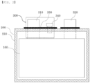
- FIG. 2 is a front view showing a pouch-type secondary battery having a gas discharge means according to a preferred embodiment of the present invention
- FIG. 3(a) is an enlarged front view showing a principal part of the pouch-type secondary battery shown in FIG. 2
- FIG. 3(b) is a plan view thereof.
- the pouch-type secondary battery includes an electrode assembly 100, a pouch-type case 200, and a lead member 300.
- the electrode assembly 100 may be a jelly-roll type electrode assembly, which is configured to have a structure in which a long sheet type positive electrode and a long sheet type negative electrode are wound in the state in which a separator is interposed between the positive electrode and the negative electrode, a stacked type electrode assembly including unit cells, each of which is configured to have a structure in which a rectangular positive electrode and a rectangular negative electrode are stacked in the state in which a separator is interposed between the positive electrode and the negative electrode, a stack/folded type electrode assembly, which is configured to have a structure in which the unit cells are wound in the state in which the unit cells are disposed on a long separation film, or a laminated/stacked type electrode assembly, which is configured to have a structure in which the unit cells are stacked so as to be attached to each other in the state in which a separator is interposed between the unit cells.
- the present invention is not limited thereto.
- the pouch-type case 200 is a case configured to receive the electrode assembly 100, and is generally configured to have a laminate sheet structure including an inner layer, a metal layer, and an outer layer.
- the inner layer directly contacts the electrode assembly 100. For this reason, it is necessary for the inner layer to exhibit an insulation property and resistance to an electrolytic solution. In addition, for isolation from the outside, it is necessary for the inner layer to exhibit sealability. That is, it is necessary for a sealed portion, formed by thermally adhering inner layers, to exhibit excellent thermal adhesive strength.
- the material for the inner layer may be selected from among a polyolefin-based resin, such as polypropylene, polyethylene, polyethylene acrylate, or polybutylene, a polyurethane resin, and a polyimide resin, which exhibit excellent chemical resistance and good sealability.
- a polyolefin-based resin such as polypropylene, polyethylene, polyethylene acrylate, or polybutylene
- a polyurethane resin such as polyethylene, polyethylene acrylate, or polybutylene
- a polyurethane resin such as polyethylene acrylate
- polybutylene such as polybutylene
- a polyurethane resin such as polyurethane resin
- polyimide resin which exhibit excellent chemical resistance and good sealability.
- Polypropylene which exhibits excellent mechanical properties, such as tensile strength, rigidity, surface hardness, and impact resistance, as well as excellent chemical resistance, is the most preferable.
- the metal layer which abuts the inner layer, corresponds to a barrier layer configured to prevent the permeation of moisture or various kinds of gases from the outside into the battery.
- An aluminum thin film which is lightweight and exhibits excellent formability, may be used as a preferred material for the metal layer.
- the outer layer is provided at the other surface of the metal layer.
- the outer layer may be made of a heatresistant polymer that exhibits excellent tensile strength, moisture permeation prevention capability, and air permeation prevention capability such that the outer layer exhibits heat resistance and chemical resistance while protecting the electrode assembly.
- the outer layer may be made of nylon or polyethylene terephthalate.
- the present invention is not limited thereto.
- the case 200 of the present invention described above may be manufactured in various manners.
- respective films of an inner layer, a metal layer, and an outer layer may be sequentially stacked, and may then be laminated to each other using dry lamination or extrusion lamination, whereby the case may be manufactured.
- a sealed portion 210 formed along the edge of the pouch-type case 200 is formed at all of four side surfaces of the pouch-type case in order to maintain the sealed state of the pouch-type secondary battery.
- the case may be thermally fused to form the sealed portion 210.
- the sealed portion 210 may be formed using methods that are usually used in the art to which the present invention pertains.
- Leads which generally include a positive electrode lead 310 and a negative electrode lead 320, are configured to have a structure in which a positive electrode tab (not shown) and a negative electrode tab (not shown), which are attached to the upper end of the electrode assembly 100, are electrically connected to the positive electrode lead 310 and the negative electrode lead 320, respectively, by welding and in which the leads are exposed out of the case 200.
- a pair of insulative films 330 which face each other, is located in the region of the sealed portion 210 at which the positive electrode lead 310 and the negative electrode lead 320 are located, and the positive and negative electrode leads 310 and 320 are disposed so as to extend through between the insulative films 330.
- a pair of insulative films 330 is located on the upper surface and the lower surface of each of the positive electrode lead 310 and the negative electrode lead 320.
- the material for the insulative films 330 may be one of a thermoplastic resin, a thermosetting resin, and a photo-curing resin, which exhibit electrical insulativity.
- the material for the insulative films may be a styrene-butadiene resin, a styrene resin, an epoxy resin, a urethane resin, an acrylic-based resin, a phenol resin, an amide-based resin, an acrylate-based resin, or a denatured resin thereof.
- the material for the insulative films is not particularly restricted, as long as the material is a resin that is capable of performing the above functions.
- a gas discharge member 340 configured to discharge the gas generated in the pouch-type case 200 to the outside.
- One side of the gas discharge member 340 is located in the pouch-type case 200, and the other side of the gas discharge member 340 protrudes out of the insulative films 330.
- a swelling phenomenon in which gas, such as carbon dioxide or carbon monoxide, is generated in the secondary battery due to various kinds of causes, such as repeated charging and discharging, overcharging, or the occurrence of a short circuit, whereby the case swells, may occur in the battery. Depending on the circumstances, the battery may even explode.
- the gas discharge member 340 is configured to discharge the gas generated in the pouch-type case 200 of the battery, as described above, to the outside.
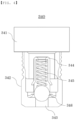
- the interior structure of a gas discharge member according to a preferred embodiment of the present invention will be described in detail with reference to FIG. 4 , which is a sectional view illustrating the interior structure of the gas discharge member.
- the gas discharge member 340 may be configured to have an approximate "T" shape including a head part 341 and a body part 342.
- the head part 341 may be omitted, whereby the gas discharge member may include only the body part 342.
- the body part 342 is provided with a gas movement passageway 343 having a predetermined inner diameter such that the gas generated in the pouch-type case 200 is movable therethrough, and a spring 345 having an outer diameter slightly less than the inner diameter of the gas movement passageway is located such that one side of the spring is caught by a catching protrusion 344 provided in the vicinity of the opening side of the gas movement passageway 343 in such a manner that the movement of the spring is restricted.
- a ball 346 configured to open and close the gas movement passageway 343 is provided at the other side of the spring 345.
- the gas discharge member 340 having the above construction, when the pressure in the pouch-type case 200 reaches a predetermined level, the ball pushes the spring 345 upwards. As a result, the generated gas is discharged to the outside through the gas movement passageway 343, whereby the occurrence of a swelling phenomenon or the explosion of the battery may be prevented. Furthermore, in the case in which the generation of gas is caused by a temporary phenomenon, the spring 345 is restored, whereby the ball closes the gas movement passageway 343 again. Consequently, it is possible to continuously use the secondary battery.
- FIGS. 5 and 6 are perspective views respectively illustrating the exterior structures of gas discharge members according to first and second modifications of the present invention
- FIG. 7 is a view showing a first embodiment illustrating the state in which the gas discharge member shown in FIG. 5 and the insulative films are joined to each other.
- the gas discharge member according to each of the modifications of the present invention is identical to the gas discharge member 340 shown in FIG. 4 in terms of the inner structure thereof, such as the gas movement passageway 343, the catching protrusion 344, the spring 345, and the ball 346, and is different from the gas discharge member shown in FIG. 4 only in terms of the external shape of the body part 342.
- the gas movement passageway 343 such as the gas movement passageway 343, the catching protrusion 344, the spring 345, and the ball 346
- the gas discharge member 340 has a concave and convex portion 347 formed at a predetermined region of the outer surface of the body part 342.
- a concave and convex portion 347 having at least one groove channel 349 formed in the longitudinal direction of the body part 342 such that gas is movable therealong, is preferably provided at the middle region of the outer surface of the body part 342, and smooth surfaces, i.e.
- non-concave and non-convex portions 348 are more preferably formed at the upper portion and the lower portion of the body part 342 such that the concave and convex portion 347 is located between the non-concave and non-convex portions.
- one end of the groove channel 349 which is directed inwards, is located on the same line as the lower edge of each of the insulative films 330 such that the gas generated in the pouch-type case 200 is introduced into the gas discharge member 340 having the concave and convex portion 347 formed between the non-concave and non-convex portions 348 described above.
- the gas discharge member 340 Since the gas discharge member 340, having the concave and convex portion 347 and the non-concave and non-convex portions 348 provided at the outer surface of the body part 342, is interposed between the insulative films 330, as described above, it is possible to securely prevent the explosion of the secondary battery due to swelling. Since the gas discharge member 340 includes the ball 346 and the spring 345 in the gas movement passageway 343, as previously described, the gas discharge member 340 is capable of discharging gas to the outside when the pressure in the pouch-type case 200 reaches a predetermined level. However, the gas may not be discharged, and thus the pouch-type case may continuously swell due to the malfunction of the ball 346 or the spring 345.
- the outer diameter of the gas discharge member 340 is preferably several tens of mm or less, more specifically 20 mm or less, in consideration of the characteristics of the secondary battery, however, restrictions are inevitably involved.
- the insulative films 330 wrap around the protruding region of the concave and convex portion 347 in the state of being attached to the protruding region of the concave and convex portion 347, a groove channel inlet 349', which is directed to the inside of the pouch-type case 200, communicates with the interior of the pouch-type case 200, and the insulative films 330 tightly contact the surface of the non-concave and non-convex portion 348 that is directed to the outside of the pouch-type case 200.
- the gas introduced through the groove channel inlet 349' moves along the groove channel 349, and the non-concave and non-convex portion 348 and the insulative films 330, which have relatively low adhesive force therebetween, are separated from each other first, whereby the gas is discharged to the center of the non-concave and non-convex portion 348, or the gas discharge member 340 is separated from the insulative films 330. Consequently, it is possible to prevent the occurrence of a large-scale accident.
- the concave and convex portion 347 is shown as protruding from the outer surface of the body part 342 in FIGS. 5 and 6 .
- the concave and convex portion 347 may be formed in the outer surface of the body part 342 in a depressed state.
- the gas discharge member 340 may be made of metal or plastic. More preferably, the gas discharge member 340 is made of metal, which exhibits relatively high sealability.
- FIG. 8 is a view showing a second embodiment illustrating the state in which the gas discharge member shown in FIG. 5 and the insulative films are joined to each other.
- one end of the groove channel 349 extends below the lower edge of each of the insulative films 330, i.e. to the interior of the case 200.
- a portion of the groove channel 349, including the groove channel inlet 349' is in a fully open state.
- gas is more easily movable, and it is not necessary to accurately align the lower edge of each of the insulative films 330 with one end of the groove channel 349, whereby manufacturing is easy.
- FIG. 9 is a view showing a third embodiment illustrating the state in which the gas discharge member shown in FIG. 5 and the insulative films are joined to each other, wherein one end of the groove channel 349 is located below the lower edge of each of the insulative films 330, and in addition, one end of the groove channel 349 extends to the end of the body part 342.
- the third embodiment has advantages similar to the advantages of the second embodiment, and therefore a detailed description thereof will be omitted.
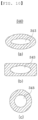
- the section of the gas discharge member 340 may be circular, oval, or quadrangular.
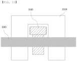
- FIG. 11 is a view showing the state in which the gas discharge member and the insulative films are joined to each other based on a deformed lead member, wherein the positive electrode lead 310 and/or the negative electrode lead 320 may be configured in a shape in which the left surface, the right surface, and the upper surface thereof surround the gas discharge member 340.
- the gas discharge member 340 is disposed in the above structure, it is possible to minimize loss of the volume of a battery pack even in the case in which the gas discharge member 340 is added, since the positive and negative electrode leads are identical to existing positive and negative electrode leads, whereby it is possible to increase the energy density of the battery pack. Furthermore, the gas discharge member 340 according to the present invention is also applicable to a battery in which the gas discharge member 340 is separately provided. In addition, there is an advantage that manufacturing is possible even though production facilities are not greatly changed.
- a gas discharge member is interposed between a pair of insulative films, whereby it is possible to discharge the gas generated in the battery to the outside and thus it is possible to prevent the occurrence of a swelling phenomenon or the explosion of the battery.
- the gas discharge member which is interposed between the pair of insulative films, is provided at the outer surface thereof with a concave and convex portion and a non-concave and non-convex portion. Even in the case in which a large amount of gas is generated, the non-concave and non-convex portion and the insulative films, which have relatively low adhesive strength therebetween, are separated from each other, and the gas is discharged to the outside. Consequently, it is possible to remarkably reduce the danger of explosion of the battery.
Landscapes
- Chemical & Material Sciences (AREA)
- Chemical Kinetics & Catalysis (AREA)
- Electrochemistry (AREA)
- General Chemical & Material Sciences (AREA)
- Inorganic Chemistry (AREA)
- Sealing Battery Cases Or Jackets (AREA)
- Gas Exhaust Devices For Batteries (AREA)
Claims (10)
- Sekundärbatterie vom Beuteltyp, welche Gasabführmittel aufweist, wobei die Sekundärbatterie vom Beuteltyp umfasst:eine Elektrodenanordnung (100), umfassend eine positive Elektrode, eine negative Elektrode und einen Separator, welcher zwischen die positive Elektrode und die negative Elektrode eingefügt ist;ein Gehäuse (200) vom Beuteltyp, welches dazu eingerichtet ist, die Elektrodenanordnung zu umhüllen;ein Paar isolierender Folien (330), welche in einem vorbestimmten Bereich eines Rands des Gehäuses (200) vom Beuteltyp angeordnet sind, um einander zugewandt zu sein;eine positive Elektrodenleitung (310), von welcher eine Seite elektrisch mit einem positive Elektrode-Stromkollektor der Elektrodenanordnung (100) verbunden ist und von welcher die andere Seite durch die isolierenden Folien (330) aus dem Gehäuse (200) vom Beuteltyp hervorsteht;eine negative Elektrodenleitung (320), von welcher eine Seite elektrisch mit einem negative Elektrode-Stromkollektor der Elektrodenanordnung (100) verbunden ist und von welcher die andere Seite durch die isolierenden Folien (330) aus dem Gehäuse vom Beuteltyp hervorsteht; undein Gasabführelement (340), welches zwischen die isolierenden Folien (330) eingefügt ist, wobei das Gasabführelement dazu eingerichtet ist, Gas, welches in dem Gehäuse (200) vom Beuteltyp erzeugt worden ist, zu einer Außenseite abzuführen,wobei das Gasabführelement (340) einen Körperteil umfasst, wobei der Körperteil (342) mit einem Gasbewegungsdurchgang (343) bereitgestellt ist, von welchem ein Inneres leer ist, wobei der Gasbewegungsdurchgang dazu eingerichtet ist, das in dem Gehäuse (200) vom Beuteltyp erzeugte Gas zu der Außenseite abzuführen, wobei eine Feder (345) und ein Ball (346), welcher dazu eingerichtet ist, den Gasbewegungsdurchgang (343) zu öffnen und zu schließen, während er sich in einem Zustand eines Angrenzens an die Feder (345) vertikal oder horizontal bewegt, in dem Gasbewegungsdurchgang (343) angeordnet sind,wobei der Körperteil (342) ferner mit einem konkaven und konvexen Abschnitt (347) bereitgestellt ist, welcher an einer äußeren Fläche davon gebildet ist,wobei der konkave und konvexe Abschnitt (347) wenigstens einen Rillenkanal (349) umfasst, welcher in einer longitudinalen Richtung des Körperteils (342) gebildet ist, undeine Seite des Rillenkanals (349), welche in einer Innenrichtung des Gehäuses vom Beuteltyp angeordnet ist, nicht mit den isolierenden Folien (330) überlappt, sodass das in dem Gehäuse (200) vom Beuteltyp erzeugte Gas in den Rillenkanal (349) eingeleitet wird.
- Sekundärbatterie vom Beuteltyp nach Anspruch 1, wobei der konkave und konvexe Abschnitt (347) lediglich an einem Abschnitt der äußeren Fläche des Körperteils (342) bereitgestellt ist.
- Sekundärbatterie vom Beuteltyp nach Anspruch 2, wobei ein nicht-konkaver und nicht-konvexer Abschnitt an einer vorbestimmten Position des Körperteils (342) bereitgestellt ist, welche zu einer Außenseite des Gehäuses vom Beuteltyp führt.
- Sekundärbatterie vom Beuteltyp nach Anspruch 3, wobei die andere Seite des Rillenkanals, an welcher der nicht-konkave und nicht-konvexe Abschnitt (348) bereitgestellt ist, derart mit den isolierenden Folien (330) überlappt, dass das in dem Gehäuse vom Beuteltyp erzeugte Gas in den Rillenkanal (349) eingeleitet wird.
- Sekundärbatterie vom Beuteltyp nach Anspruch 1, wobei ein Abschnitt des Rillenkanals (349), welcher in einer Innenrichtung des Gehäuses vom Beuteltyp angeordnet ist, mit einem Inneren des Gehäuses vom Beuteltyp in Verbindung steht, sodass das in dem Gehäuse vom Beuteltyp erzeugte Gas in den Rillenkanal (349) eingeleitet wird.
- Sekundärbatterie vom Beuteltyp nach Anspruch 5, wobei ein nicht-konkaver und nicht-konvexer Abschnitt (348) an einer vorbestimmten Position des Körperteils (342) bereitgestellt ist, welche zu einer Außenseite des Gehäuses vom Beuteltyp führt, wobei der nicht-konkave und nicht-konvexe Abschnitt (348) derart angeordnet ist, dass er die isolierenden Folien (330) überlappt.
- Sekundärbatterie vom Beuteltyp nach Anspruch 1, wobei der Körperteil (342) einen jeglichen aufweist, aus einem kreisförmigen Querschnitt, einem ovalen Querschnitt und einem viereckigen Querschnitt.
- Sekundärbatterie vom Beuteltyp nach Anspruch 1, wobei das Gasabführelement (340) aus Metall oder Kunststoff hergestellt ist.
- Batteriemodul, umfassend die Sekundärbatterie vom Beuteltyp nach einem der Ansprüche 1 bis 8.
- Batteriepack, umfassend das Batteriemodul nach Anspruch 9.
Applications Claiming Priority (2)
| Application Number | Priority Date | Filing Date | Title |
|---|---|---|---|
| KR1020180046749A KR102361569B1 (ko) | 2018-04-23 | 2018-04-23 | 가스배출수단이 구비된 파우치형 이차전지 |
| PCT/KR2019/001034 WO2019208911A1 (ko) | 2018-04-23 | 2019-01-24 | 가스배출수단이 구비된 파우치형 이차전지 |
Publications (3)
| Publication Number | Publication Date |
|---|---|
| EP3671898A1 EP3671898A1 (de) | 2020-06-24 |
| EP3671898A4 EP3671898A4 (de) | 2020-12-09 |
| EP3671898B1 true EP3671898B1 (de) | 2024-08-14 |
Family
ID=68294610
Family Applications (1)
| Application Number | Title | Priority Date | Filing Date |
|---|---|---|---|
| EP19792234.7A Active EP3671898B1 (de) | 2018-04-23 | 2019-01-24 | Beutelartige sekundärbatterie mit gasentladungsmitteln |
Country Status (8)
| Country | Link |
|---|---|
| US (1) | US11177532B2 (de) |
| EP (1) | EP3671898B1 (de) |
| JP (1) | JP7049541B2 (de) |
| KR (1) | KR102361569B1 (de) |
| CN (1) | CN111033799B (de) |
| ES (1) | ES2986418T3 (de) |
| HU (1) | HUE068343T2 (de) |
| WO (1) | WO2019208911A1 (de) |
Families Citing this family (21)
| Publication number | Priority date | Publication date | Assignee | Title |
|---|---|---|---|---|
| KR102341465B1 (ko) * | 2018-05-10 | 2021-12-22 | 주식회사 엘지에너지솔루션 | 벤팅 장치 및 그의 제조 방법 |
| KR102773520B1 (ko) * | 2019-10-31 | 2025-02-27 | 에스케이온 주식회사 | 파우치형 이차전지 및 이의 제조 방법 |
| KR102807656B1 (ko) * | 2020-05-13 | 2025-05-14 | 주식회사 엘지에너지솔루션 | 이차전지 |
| KR102756131B1 (ko) * | 2020-06-15 | 2025-01-17 | 주식회사 엘지에너지솔루션 | 이차전지 |
| KR102845440B1 (ko) * | 2020-06-15 | 2025-08-12 | 주식회사 엘지에너지솔루션 | 이차전지 |
| KR102736110B1 (ko) * | 2020-07-10 | 2024-12-02 | 주식회사 엘지에너지솔루션 | 이차전지 |
| US20230084670A1 (en) * | 2020-11-06 | 2023-03-16 | Lg Energy Solution, Ltd. | Battery Cell and Battery Module Including the Same |
| CN115606049A (zh) | 2020-12-08 | 2023-01-13 | 株式会社Lg新能源(Kr) | 二次电池和包括该二次电池的电池模块 |
| JP7498302B2 (ja) * | 2021-01-11 | 2024-06-11 | エルジー エナジー ソリューション リミテッド | 電池セル及びそれを含む電池モジュール |
| US12283709B2 (en) * | 2021-01-25 | 2025-04-22 | Lg Energy Solution, Ltd. | Venting device for secondary batteries and pouch-shaped secondary battery including the same |
| ES3027284T3 (en) * | 2021-01-28 | 2025-06-13 | Lg Energy Solution Ltd | Battery cell and battery cell manufacturing apparatus |
| CN120657338A (zh) | 2021-02-04 | 2025-09-16 | 株式会社Lg新能源 | 电池电芯和包括该电池电芯的电池模块 |
| US20220336917A1 (en) * | 2021-04-14 | 2022-10-20 | Lg Energy Solution, Ltd. | Secondary Battery |
| US12476312B2 (en) | 2021-04-15 | 2025-11-18 | Lg Energy Solution, Ltd. | Secondary battery |
| US12294105B2 (en) * | 2021-04-15 | 2025-05-06 | Lg Energy Solution, Ltd. | Secondary battery |
| KR20230025140A (ko) * | 2021-08-13 | 2023-02-21 | 주식회사 엘지에너지솔루션 | 이차전지용 파우치 백 및 이를 포함하는 파우치형 이차전지 |
| KR20230071273A (ko) | 2021-11-16 | 2023-05-23 | 주식회사 엘지에너지솔루션 | 벤팅 장치 및 이를 포함하는 이차전지 |
| DE102022200014A1 (de) | 2022-01-04 | 2023-07-06 | Volkswagen Aktiengesellschaft | Sicherheitsvorrichtung zur Anordnung in einer Zellwandung einer Batteriezelle, Batteriezelle, Batteriemodul sowie Herstellverfahren für eine Batteriezelle |
| DE102023122196A1 (de) * | 2023-08-18 | 2025-02-20 | Carl Freudenberg Kg | Energiespeicherzelle |
| FR3152657A1 (fr) * | 2023-08-31 | 2025-03-07 | Renault S.A.S | Ensemble comprenant une cellule de batterie et procédé de récupération d’un ou plusieurs gaz émis lors de la formation d’une batterie |
| KR20250059064A (ko) | 2023-10-24 | 2025-05-02 | (주)동양티피엘 | 이차전지의 전지케이스 통기공 차단용 인슐레이션 시트 제작을 위한 양면테이프 공급장치 |
Family Cites Families (16)
| Publication number | Priority date | Publication date | Assignee | Title |
|---|---|---|---|---|
| KR19980060805A (ko) | 1996-12-31 | 1998-10-07 | 손욱 | 전지의 캡 조립체 |
| JP4867158B2 (ja) * | 2004-11-19 | 2012-02-01 | トヨタ自動車株式会社 | フィルム外装型蓄電装置 |
| US8071231B2 (en) * | 2006-08-28 | 2011-12-06 | Lg Chem, Ltd. | Secondary battery including one-way exhaust valve |
| CN101651194A (zh) * | 2008-08-14 | 2010-02-17 | 上海比亚迪有限公司 | 一种锂离子电池 |
| KR101049820B1 (ko) | 2008-08-04 | 2011-07-15 | 삼성에스디아이 주식회사 | 이차 전지 |
| KR101245284B1 (ko) * | 2010-12-20 | 2013-03-19 | 주식회사 엘지화학 | 전해액 재충전이 가능한 이차 전지 |
| KR20130048419A (ko) | 2011-11-02 | 2013-05-10 | 에스케이이노베이션 주식회사 | 파우치형 이차전지 |
| KR101908583B1 (ko) * | 2012-06-28 | 2018-10-17 | 에스케이이노베이션 주식회사 | 가스 포집 및 배출이 용이한 이차전지모듈 |
| KR101268296B1 (ko) * | 2012-11-16 | 2013-05-28 | 주식회사 유니크 | 축전지용 벤트 캡 |
| KR102257850B1 (ko) | 2014-07-18 | 2021-05-28 | 에스케이이노베이션 주식회사 | 관형 통로체를 갖는 파우치형 리튬 이차전지 |
| KR102275273B1 (ko) * | 2014-07-29 | 2021-07-09 | 에스케이이노베이션 주식회사 | 파우치형 리튬 이차전지의 벤팅 시스템 |
| DE102014018751A1 (de) * | 2014-12-16 | 2016-06-16 | Daimler Ag | Elektrochemischer Energiespeicher und Batterie |
| KR20160102615A (ko) * | 2015-02-23 | 2016-08-31 | 박준혁 | 농약 분무기용 양방향 피스톤 복열식 고효율 펌프장치 |
| KR102318043B1 (ko) * | 2015-04-22 | 2021-10-28 | 에스케이이노베이션 주식회사 | 이차전지 및 이를 포함하는 배터리 모듈 |
| KR101904587B1 (ko) * | 2015-09-01 | 2018-10-04 | 주식회사 엘지화학 | 전지셀 및 그의 제조방법 |
| KR101877534B1 (ko) | 2016-10-28 | 2018-07-11 | 주종문 | 식물재배 베드 장착용 분무 수경 플랫폼 조립체 |
-
2018
- 2018-04-23 KR KR1020180046749A patent/KR102361569B1/ko active Active
-
2019
- 2019-01-24 EP EP19792234.7A patent/EP3671898B1/de active Active
- 2019-01-24 CN CN201980003936.0A patent/CN111033799B/zh active Active
- 2019-01-24 JP JP2020515721A patent/JP7049541B2/ja active Active
- 2019-01-24 WO PCT/KR2019/001034 patent/WO2019208911A1/ko not_active Ceased
- 2019-01-24 ES ES19792234T patent/ES2986418T3/es active Active
- 2019-01-24 HU HUE19792234A patent/HUE068343T2/hu unknown
- 2019-01-24 US US16/753,442 patent/US11177532B2/en active Active
Also Published As
| Publication number | Publication date |
|---|---|
| JP2020534650A (ja) | 2020-11-26 |
| KR102361569B1 (ko) | 2022-02-10 |
| US20200321577A1 (en) | 2020-10-08 |
| ES2986418T3 (es) | 2024-11-11 |
| US11177532B2 (en) | 2021-11-16 |
| CN111033799A (zh) | 2020-04-17 |
| WO2019208911A1 (ko) | 2019-10-31 |
| KR20190123059A (ko) | 2019-10-31 |
| HUE068343T2 (hu) | 2024-12-28 |
| JP7049541B2 (ja) | 2022-04-07 |
| EP3671898A4 (de) | 2020-12-09 |
| CN111033799B (zh) | 2022-03-25 |
| EP3671898A1 (de) | 2020-06-24 |
Similar Documents
| Publication | Publication Date | Title |
|---|---|---|
| EP3671898B1 (de) | Beutelartige sekundärbatterie mit gasentladungsmitteln | |
| US7718306B2 (en) | Rechargeable battery with gas release safety vent | |
| EP2156488B1 (de) | Batteriezelle mit verbesserter sicherheit | |
| KR100973310B1 (ko) | 이차 전지용 전극 탭 및 이를 구비하는 이차 전지 | |
| CN110088944B (zh) | 包括使用导电聚合物的电极引线的袋形二次电池 | |
| CN101404325B (zh) | 盖组件及使用该盖组件的二次电池 | |
| KR101472167B1 (ko) | 안전성이 향상된 이차전지용 파우치 및 이를 이용한 파우치형 이차전지, 중대형 전지팩 | |
| JP7146335B2 (ja) | ベンティング装置 | |
| KR101273472B1 (ko) | 파우치형 이차 전지의 제조 방법 및 이에 의한 파우치형 이차 전지 | |
| EP3998674A1 (de) | Sekundärbatterie | |
| US20110143177A1 (en) | Secondary battery and manufacturing method thereof | |
| EP4075562A1 (de) | Batteriezelle mit verbesserter sicherheit und verfahren zu ihrer herstellung | |
| EP4164043B1 (de) | Beutelförmige batteriezelle mit vorrichtung zum entlüften eines versiegelten abschnitts | |
| US10535859B2 (en) | Pouch-shaped secondary battery including micro-perforated electrode lead having adhesive properties | |
| EP4216356B1 (de) | Beutelförmige batteriezelle mit verbesserter sicherheit | |
| EP4243194A1 (de) | Beutelartige batteriezelle mit verbesserter thermischer stabilität |
Legal Events
| Date | Code | Title | Description |
|---|---|---|---|
| STAA | Information on the status of an ep patent application or granted ep patent |
Free format text: STATUS: THE INTERNATIONAL PUBLICATION HAS BEEN MADE |
|
| PUAI | Public reference made under article 153(3) epc to a published international application that has entered the european phase |
Free format text: ORIGINAL CODE: 0009012 |
|
| STAA | Information on the status of an ep patent application or granted ep patent |
Free format text: STATUS: REQUEST FOR EXAMINATION WAS MADE |
|
| 17P | Request for examination filed |
Effective date: 20200317 |
|
| AK | Designated contracting states |
Kind code of ref document: A1 Designated state(s): AL AT BE BG CH CY CZ DE DK EE ES FI FR GB GR HR HU IE IS IT LI LT LU LV MC MK MT NL NO PL PT RO RS SE SI SK SM TR |
|
| AX | Request for extension of the european patent |
Extension state: BA ME |
|
| A4 | Supplementary search report drawn up and despatched |
Effective date: 20201109 |
|
| RIC1 | Information provided on ipc code assigned before grant |
Ipc: H01M 2/06 20060101ALI20201103BHEP Ipc: H01M 2/12 20060101AFI20201103BHEP Ipc: H01M 2/30 20060101ALI20201103BHEP Ipc: H01M 2/02 20060101ALI20201103BHEP |
|
| DAV | Request for validation of the european patent (deleted) | ||
| DAX | Request for extension of the european patent (deleted) | ||
| RAP1 | Party data changed (applicant data changed or rights of an application transferred) |
Owner name: LG ENERGY SOLUTION LTD. |
|
| RAP3 | Party data changed (applicant data changed or rights of an application transferred) |
Owner name: LG ENERGY SOLUTION, LTD. |
|
| REG | Reference to a national code |
Ref country code: DE Ref legal event code: R079 Free format text: PREVIOUS MAIN CLASS: H01M0002120000 Ipc: H01M0050178000 Ref country code: DE Ref legal event code: R079 Ref document number: 602019057051 Country of ref document: DE Free format text: PREVIOUS MAIN CLASS: H01M0002120000 Ipc: H01M0050178000 |
|
| GRAP | Despatch of communication of intention to grant a patent |
Free format text: ORIGINAL CODE: EPIDOSNIGR1 |
|
| STAA | Information on the status of an ep patent application or granted ep patent |
Free format text: STATUS: GRANT OF PATENT IS INTENDED |
|
| RIC1 | Information provided on ipc code assigned before grant |
Ipc: H01M 50/129 20210101ALN20240409BHEP Ipc: H01M 50/121 20210101ALN20240409BHEP Ipc: H01M 50/119 20210101ALN20240409BHEP Ipc: H01M 50/595 20210101ALI20240409BHEP Ipc: H01M 50/588 20210101ALI20240409BHEP Ipc: H01M 50/553 20210101ALI20240409BHEP Ipc: H01M 50/105 20210101ALI20240409BHEP Ipc: H01M 50/55 20210101ALI20240409BHEP Ipc: H01M 50/531 20210101ALI20240409BHEP Ipc: H01M 50/342 20210101ALI20240409BHEP Ipc: H01M 50/333 20210101ALI20240409BHEP Ipc: H01M 50/325 20210101ALI20240409BHEP Ipc: H01M 50/178 20210101AFI20240409BHEP |
|
| INTG | Intention to grant announced |
Effective date: 20240424 |
|
| P01 | Opt-out of the competence of the unified patent court (upc) registered |
Effective date: 20240430 |
|
| GRAS | Grant fee paid |
Free format text: ORIGINAL CODE: EPIDOSNIGR3 |
|
| GRAA | (expected) grant |
Free format text: ORIGINAL CODE: 0009210 |
|
| STAA | Information on the status of an ep patent application or granted ep patent |
Free format text: STATUS: THE PATENT HAS BEEN GRANTED |
|
| AK | Designated contracting states |
Kind code of ref document: B1 Designated state(s): AL AT BE BG CH CY CZ DE DK EE ES FI FR GB GR HR HU IE IS IT LI LT LU LV MC MK MT NL NO PL PT RO RS SE SI SK SM TR |
|
| REG | Reference to a national code |
Ref country code: GB Ref legal event code: FG4D |
|
| REG | Reference to a national code |
Ref country code: CH Ref legal event code: EP |
|
| REG | Reference to a national code |
Ref country code: DE Ref legal event code: R096 Ref document number: 602019057051 Country of ref document: DE |
|
| REG | Reference to a national code |
Ref country code: IE Ref legal event code: FG4D |
|
| REG | Reference to a national code |
Ref country code: ES Ref legal event code: FG2A Ref document number: 2986418 Country of ref document: ES Kind code of ref document: T3 Effective date: 20241111 |
|
| REG | Reference to a national code |
Ref country code: LT Ref legal event code: MG9D |
|
| REG | Reference to a national code |
Ref country code: NL Ref legal event code: MP Effective date: 20240814 |
|
| REG | Reference to a national code |
Ref country code: HU Ref legal event code: AG4A Ref document number: E068343 Country of ref document: HU |
|
| PG25 | Lapsed in a contracting state [announced via postgrant information from national office to epo] |
Ref country code: NO Free format text: LAPSE BECAUSE OF FAILURE TO SUBMIT A TRANSLATION OF THE DESCRIPTION OR TO PAY THE FEE WITHIN THE PRESCRIBED TIME-LIMIT Effective date: 20241114 |
|
| REG | Reference to a national code |
Ref country code: AT Ref legal event code: MK05 Ref document number: 1714150 Country of ref document: AT Kind code of ref document: T Effective date: 20240814 |
|
| PG25 | Lapsed in a contracting state [announced via postgrant information from national office to epo] |
Ref country code: FI Free format text: LAPSE BECAUSE OF FAILURE TO SUBMIT A TRANSLATION OF THE DESCRIPTION OR TO PAY THE FEE WITHIN THE PRESCRIBED TIME-LIMIT Effective date: 20240814 Ref country code: NL Free format text: LAPSE BECAUSE OF FAILURE TO SUBMIT A TRANSLATION OF THE DESCRIPTION OR TO PAY THE FEE WITHIN THE PRESCRIBED TIME-LIMIT Effective date: 20240814 Ref country code: GR Free format text: LAPSE BECAUSE OF FAILURE TO SUBMIT A TRANSLATION OF THE DESCRIPTION OR TO PAY THE FEE WITHIN THE PRESCRIBED TIME-LIMIT Effective date: 20241115 Ref country code: PT Free format text: LAPSE BECAUSE OF FAILURE TO SUBMIT A TRANSLATION OF THE DESCRIPTION OR TO PAY THE FEE WITHIN THE PRESCRIBED TIME-LIMIT Effective date: 20241216 Ref country code: PL Free format text: LAPSE BECAUSE OF FAILURE TO SUBMIT A TRANSLATION OF THE DESCRIPTION OR TO PAY THE FEE WITHIN THE PRESCRIBED TIME-LIMIT Effective date: 20240814 |
|
| PG25 | Lapsed in a contracting state [announced via postgrant information from national office to epo] |
Ref country code: BG Free format text: LAPSE BECAUSE OF FAILURE TO SUBMIT A TRANSLATION OF THE DESCRIPTION OR TO PAY THE FEE WITHIN THE PRESCRIBED TIME-LIMIT Effective date: 20240814 |
|
| PG25 | Lapsed in a contracting state [announced via postgrant information from national office to epo] |
Ref country code: LV Free format text: LAPSE BECAUSE OF FAILURE TO SUBMIT A TRANSLATION OF THE DESCRIPTION OR TO PAY THE FEE WITHIN THE PRESCRIBED TIME-LIMIT Effective date: 20240814 |
|
| PG25 | Lapsed in a contracting state [announced via postgrant information from national office to epo] |
Ref country code: IS Free format text: LAPSE BECAUSE OF FAILURE TO SUBMIT A TRANSLATION OF THE DESCRIPTION OR TO PAY THE FEE WITHIN THE PRESCRIBED TIME-LIMIT Effective date: 20241214 Ref country code: AT Free format text: LAPSE BECAUSE OF FAILURE TO SUBMIT A TRANSLATION OF THE DESCRIPTION OR TO PAY THE FEE WITHIN THE PRESCRIBED TIME-LIMIT Effective date: 20240814 |
|
| PG25 | Lapsed in a contracting state [announced via postgrant information from national office to epo] |
Ref country code: HR Free format text: LAPSE BECAUSE OF FAILURE TO SUBMIT A TRANSLATION OF THE DESCRIPTION OR TO PAY THE FEE WITHIN THE PRESCRIBED TIME-LIMIT Effective date: 20240814 |
|
| PG25 | Lapsed in a contracting state [announced via postgrant information from national office to epo] |
Ref country code: RS Free format text: LAPSE BECAUSE OF FAILURE TO SUBMIT A TRANSLATION OF THE DESCRIPTION OR TO PAY THE FEE WITHIN THE PRESCRIBED TIME-LIMIT Effective date: 20241114 |
|
| PG25 | Lapsed in a contracting state [announced via postgrant information from national office to epo] |
Ref country code: RS Free format text: LAPSE BECAUSE OF FAILURE TO SUBMIT A TRANSLATION OF THE DESCRIPTION OR TO PAY THE FEE WITHIN THE PRESCRIBED TIME-LIMIT Effective date: 20241114 Ref country code: PT Free format text: LAPSE BECAUSE OF FAILURE TO SUBMIT A TRANSLATION OF THE DESCRIPTION OR TO PAY THE FEE WITHIN THE PRESCRIBED TIME-LIMIT Effective date: 20241216 Ref country code: PL Free format text: LAPSE BECAUSE OF FAILURE TO SUBMIT A TRANSLATION OF THE DESCRIPTION OR TO PAY THE FEE WITHIN THE PRESCRIBED TIME-LIMIT Effective date: 20240814 Ref country code: NO Free format text: LAPSE BECAUSE OF FAILURE TO SUBMIT A TRANSLATION OF THE DESCRIPTION OR TO PAY THE FEE WITHIN THE PRESCRIBED TIME-LIMIT Effective date: 20241114 Ref country code: NL Free format text: LAPSE BECAUSE OF FAILURE TO SUBMIT A TRANSLATION OF THE DESCRIPTION OR TO PAY THE FEE WITHIN THE PRESCRIBED TIME-LIMIT Effective date: 20240814 Ref country code: LV Free format text: LAPSE BECAUSE OF FAILURE TO SUBMIT A TRANSLATION OF THE DESCRIPTION OR TO PAY THE FEE WITHIN THE PRESCRIBED TIME-LIMIT Effective date: 20240814 Ref country code: IS Free format text: LAPSE BECAUSE OF FAILURE TO SUBMIT A TRANSLATION OF THE DESCRIPTION OR TO PAY THE FEE WITHIN THE PRESCRIBED TIME-LIMIT Effective date: 20241214 Ref country code: HR Free format text: LAPSE BECAUSE OF FAILURE TO SUBMIT A TRANSLATION OF THE DESCRIPTION OR TO PAY THE FEE WITHIN THE PRESCRIBED TIME-LIMIT Effective date: 20240814 Ref country code: GR Free format text: LAPSE BECAUSE OF FAILURE TO SUBMIT A TRANSLATION OF THE DESCRIPTION OR TO PAY THE FEE WITHIN THE PRESCRIBED TIME-LIMIT Effective date: 20241115 Ref country code: FI Free format text: LAPSE BECAUSE OF FAILURE TO SUBMIT A TRANSLATION OF THE DESCRIPTION OR TO PAY THE FEE WITHIN THE PRESCRIBED TIME-LIMIT Effective date: 20240814 Ref country code: BG Free format text: LAPSE BECAUSE OF FAILURE TO SUBMIT A TRANSLATION OF THE DESCRIPTION OR TO PAY THE FEE WITHIN THE PRESCRIBED TIME-LIMIT Effective date: 20240814 Ref country code: AT Free format text: LAPSE BECAUSE OF FAILURE TO SUBMIT A TRANSLATION OF THE DESCRIPTION OR TO PAY THE FEE WITHIN THE PRESCRIBED TIME-LIMIT Effective date: 20240814 |
|
| PGFP | Annual fee paid to national office [announced via postgrant information from national office to epo] |
Ref country code: HU Payment date: 20250117 Year of fee payment: 7 |
|
| PGFP | Annual fee paid to national office [announced via postgrant information from national office to epo] |
Ref country code: DE Payment date: 20241223 Year of fee payment: 7 |
|
| PG25 | Lapsed in a contracting state [announced via postgrant information from national office to epo] |
Ref country code: DK Free format text: LAPSE BECAUSE OF FAILURE TO SUBMIT A TRANSLATION OF THE DESCRIPTION OR TO PAY THE FEE WITHIN THE PRESCRIBED TIME-LIMIT Effective date: 20240814 Ref country code: RO Free format text: LAPSE BECAUSE OF FAILURE TO SUBMIT A TRANSLATION OF THE DESCRIPTION OR TO PAY THE FEE WITHIN THE PRESCRIBED TIME-LIMIT Effective date: 20240814 Ref country code: SM Free format text: LAPSE BECAUSE OF FAILURE TO SUBMIT A TRANSLATION OF THE DESCRIPTION OR TO PAY THE FEE WITHIN THE PRESCRIBED TIME-LIMIT Effective date: 20240814 |
|
| PGFP | Annual fee paid to national office [announced via postgrant information from national office to epo] |
Ref country code: ES Payment date: 20250207 Year of fee payment: 7 |
|
| PG25 | Lapsed in a contracting state [announced via postgrant information from national office to epo] |
Ref country code: EE Free format text: LAPSE BECAUSE OF FAILURE TO SUBMIT A TRANSLATION OF THE DESCRIPTION OR TO PAY THE FEE WITHIN THE PRESCRIBED TIME-LIMIT Effective date: 20240814 |
|
| PG25 | Lapsed in a contracting state [announced via postgrant information from national office to epo] |
Ref country code: CZ Free format text: LAPSE BECAUSE OF FAILURE TO SUBMIT A TRANSLATION OF THE DESCRIPTION OR TO PAY THE FEE WITHIN THE PRESCRIBED TIME-LIMIT Effective date: 20240814 |
|
| PG25 | Lapsed in a contracting state [announced via postgrant information from national office to epo] |
Ref country code: SK Free format text: LAPSE BECAUSE OF FAILURE TO SUBMIT A TRANSLATION OF THE DESCRIPTION OR TO PAY THE FEE WITHIN THE PRESCRIBED TIME-LIMIT Effective date: 20240814 Ref country code: IT Free format text: LAPSE BECAUSE OF FAILURE TO SUBMIT A TRANSLATION OF THE DESCRIPTION OR TO PAY THE FEE WITHIN THE PRESCRIBED TIME-LIMIT Effective date: 20240814 |
|
| REG | Reference to a national code |
Ref country code: DE Ref legal event code: R097 Ref document number: 602019057051 Country of ref document: DE |
|
| PLBE | No opposition filed within time limit |
Free format text: ORIGINAL CODE: 0009261 |
|
| STAA | Information on the status of an ep patent application or granted ep patent |
Free format text: STATUS: NO OPPOSITION FILED WITHIN TIME LIMIT |
|
| 26N | No opposition filed |
Effective date: 20250515 |
|
| REG | Reference to a national code |
Ref country code: CH Ref legal event code: PL |
|
| PG25 | Lapsed in a contracting state [announced via postgrant information from national office to epo] |
Ref country code: SE Free format text: LAPSE BECAUSE OF FAILURE TO SUBMIT A TRANSLATION OF THE DESCRIPTION OR TO PAY THE FEE WITHIN THE PRESCRIBED TIME-LIMIT Effective date: 20240814 |
|
| PG25 | Lapsed in a contracting state [announced via postgrant information from national office to epo] |
Ref country code: MC Free format text: LAPSE BECAUSE OF FAILURE TO SUBMIT A TRANSLATION OF THE DESCRIPTION OR TO PAY THE FEE WITHIN THE PRESCRIBED TIME-LIMIT Effective date: 20240814 Ref country code: LU Free format text: LAPSE BECAUSE OF NON-PAYMENT OF DUE FEES Effective date: 20250124 |
|
| PG25 | Lapsed in a contracting state [announced via postgrant information from national office to epo] |
Ref country code: CH Free format text: LAPSE BECAUSE OF NON-PAYMENT OF DUE FEES Effective date: 20250131 |
|
| PGFP | Annual fee paid to national office [announced via postgrant information from national office to epo] |
Ref country code: GB Payment date: 20251222 Year of fee payment: 8 |
|
| PGFP | Annual fee paid to national office [announced via postgrant information from national office to epo] |
Ref country code: FR Payment date: 20251223 Year of fee payment: 8 |
|
| PGFP | Annual fee paid to national office [announced via postgrant information from national office to epo] |
Ref country code: BE Payment date: 20251229 Year of fee payment: 8 |
|
| PG25 | Lapsed in a contracting state [announced via postgrant information from national office to epo] |
Ref country code: IE Free format text: LAPSE BECAUSE OF NON-PAYMENT OF DUE FEES Effective date: 20250124 |