EP4071100A1 - Windenvorrichtung, insbesondere für eine baugeräteanordnung - Google Patents
Windenvorrichtung, insbesondere für eine baugeräteanordnung Download PDFInfo
- Publication number
- EP4071100A1 EP4071100A1 EP21167443.7A EP21167443A EP4071100A1 EP 4071100 A1 EP4071100 A1 EP 4071100A1 EP 21167443 A EP21167443 A EP 21167443A EP 4071100 A1 EP4071100 A1 EP 4071100A1
- Authority
- EP
- European Patent Office
- Prior art keywords
- winch
- drum
- rotary
- winch drum
- rotary drive
- Prior art date
- Legal status (The legal status is an assumption and is not a legal conclusion. Google has not performed a legal analysis and makes no representation as to the accuracy of the status listed.)
- Granted
Links
Images

Classifications
-
- B—PERFORMING OPERATIONS; TRANSPORTING
- B66—HOISTING; LIFTING; HAULING
- B66D—CAPSTANS; WINCHES; TACKLES, e.g. PULLEY BLOCKS; HOISTS
- B66D1/00—Rope, cable, or chain winding mechanisms; Capstans
- B66D1/02—Driving gear
- B66D1/14—Power transmissions between power sources and drums or barrels
-
- B—PERFORMING OPERATIONS; TRANSPORTING
- B65—CONVEYING; PACKING; STORING; HANDLING THIN OR FILAMENTARY MATERIAL
- B65H—HANDLING THIN OR FILAMENTARY MATERIAL, e.g. SHEETS, WEBS, CABLES
- B65H75/00—Storing webs, tapes, or filamentary material, e.g. on reels
- B65H75/02—Cores, formers, supports, or holders for coiled, wound, or folded material, e.g. reels, spindles, bobbins, cop tubes, cans, mandrels or chucks
- B65H75/04—Kinds or types
- B65H75/08—Kinds or types of circular or polygonal cross-section
- B65H75/14—Kinds or types of circular or polygonal cross-section with two end flanges
-
- B—PERFORMING OPERATIONS; TRANSPORTING
- B65—CONVEYING; PACKING; STORING; HANDLING THIN OR FILAMENTARY MATERIAL
- B65H—HANDLING THIN OR FILAMENTARY MATERIAL, e.g. SHEETS, WEBS, CABLES
- B65H75/00—Storing webs, tapes, or filamentary material, e.g. on reels
- B65H75/02—Cores, formers, supports, or holders for coiled, wound, or folded material, e.g. reels, spindles, bobbins, cop tubes, cans, mandrels or chucks
- B65H75/18—Constructional details
- B65H75/26—Arrangements for preventing slipping of winding
- B65H75/265—Reels with grooves or grooved elements inhibiting aligned or orderly winding
-
- B—PERFORMING OPERATIONS; TRANSPORTING
- B65—CONVEYING; PACKING; STORING; HANDLING THIN OR FILAMENTARY MATERIAL
- B65H—HANDLING THIN OR FILAMENTARY MATERIAL, e.g. SHEETS, WEBS, CABLES
- B65H75/00—Storing webs, tapes, or filamentary material, e.g. on reels
- B65H75/02—Cores, formers, supports, or holders for coiled, wound, or folded material, e.g. reels, spindles, bobbins, cop tubes, cans, mandrels or chucks
- B65H75/18—Constructional details
- B65H75/30—Arrangements to facilitate driving or braking
-
- B—PERFORMING OPERATIONS; TRANSPORTING
- B65—CONVEYING; PACKING; STORING; HANDLING THIN OR FILAMENTARY MATERIAL
- B65H—HANDLING THIN OR FILAMENTARY MATERIAL, e.g. SHEETS, WEBS, CABLES
- B65H75/00—Storing webs, tapes, or filamentary material, e.g. on reels
- B65H75/02—Cores, formers, supports, or holders for coiled, wound, or folded material, e.g. reels, spindles, bobbins, cop tubes, cans, mandrels or chucks
- B65H75/34—Cores, formers, supports, or holders for coiled, wound, or folded material, e.g. reels, spindles, bobbins, cop tubes, cans, mandrels or chucks specially adapted or mounted for storing and repeatedly paying-out and re-storing lengths of material provided for particular purposes, e.g. anchored hoses, power cables
- B65H75/38—Cores, formers, supports, or holders for coiled, wound, or folded material, e.g. reels, spindles, bobbins, cop tubes, cans, mandrels or chucks specially adapted or mounted for storing and repeatedly paying-out and re-storing lengths of material provided for particular purposes, e.g. anchored hoses, power cables involving the use of a core or former internal to, and supporting, a stored package of material
- B65H75/44—Constructional details
- B65H75/4402—Guiding arrangements to control paying-out and re-storing of the material
-
- B—PERFORMING OPERATIONS; TRANSPORTING
- B65—CONVEYING; PACKING; STORING; HANDLING THIN OR FILAMENTARY MATERIAL
- B65H—HANDLING THIN OR FILAMENTARY MATERIAL, e.g. SHEETS, WEBS, CABLES
- B65H75/00—Storing webs, tapes, or filamentary material, e.g. on reels
- B65H75/02—Cores, formers, supports, or holders for coiled, wound, or folded material, e.g. reels, spindles, bobbins, cop tubes, cans, mandrels or chucks
- B65H75/34—Cores, formers, supports, or holders for coiled, wound, or folded material, e.g. reels, spindles, bobbins, cop tubes, cans, mandrels or chucks specially adapted or mounted for storing and repeatedly paying-out and re-storing lengths of material provided for particular purposes, e.g. anchored hoses, power cables
- B65H75/38—Cores, formers, supports, or holders for coiled, wound, or folded material, e.g. reels, spindles, bobbins, cop tubes, cans, mandrels or chucks specially adapted or mounted for storing and repeatedly paying-out and re-storing lengths of material provided for particular purposes, e.g. anchored hoses, power cables involving the use of a core or former internal to, and supporting, a stored package of material
- B65H75/44—Constructional details
- B65H75/4481—Arrangements or adaptations for driving the reel or the material
-
- B—PERFORMING OPERATIONS; TRANSPORTING
- B66—HOISTING; LIFTING; HAULING
- B66D—CAPSTANS; WINCHES; TACKLES, e.g. PULLEY BLOCKS; HOISTS
- B66D1/00—Rope, cable, or chain winding mechanisms; Capstans
- B66D1/02—Driving gear
- B66D1/08—Driving gear incorporating fluid motors
-
- B—PERFORMING OPERATIONS; TRANSPORTING
- B66—HOISTING; LIFTING; HAULING
- B66D—CAPSTANS; WINCHES; TACKLES, e.g. PULLEY BLOCKS; HOISTS
- B66D1/00—Rope, cable, or chain winding mechanisms; Capstans
- B66D1/02—Driving gear
- B66D1/12—Driving gear incorporating electric motors
-
- B—PERFORMING OPERATIONS; TRANSPORTING
- B66—HOISTING; LIFTING; HAULING
- B66D—CAPSTANS; WINCHES; TACKLES, e.g. PULLEY BLOCKS; HOISTS
- B66D1/00—Rope, cable, or chain winding mechanisms; Capstans
- B66D1/28—Other constructional details
- B66D1/30—Rope, cable, or chain drums or barrels
-
- E—FIXED CONSTRUCTIONS
- E04—BUILDING
- E04G—SCAFFOLDING; FORMS; SHUTTERING; BUILDING IMPLEMENTS OR AIDS, OR THEIR USE; HANDLING BUILDING MATERIALS ON THE SITE; REPAIRING, BREAKING-UP OR OTHER WORK ON EXISTING BUILDINGS
- E04G23/00—Working measures on existing buildings
- E04G23/08—Wrecking of buildings
- E04G23/082—Wrecking of buildings using shears, breakers, jaws and the like
-
- B—PERFORMING OPERATIONS; TRANSPORTING
- B65—CONVEYING; PACKING; STORING; HANDLING THIN OR FILAMENTARY MATERIAL
- B65H—HANDLING THIN OR FILAMENTARY MATERIAL, e.g. SHEETS, WEBS, CABLES
- B65H2301/00—Handling processes for sheets or webs
- B65H2301/40—Type of handling process
- B65H2301/41—Winding, unwinding
- B65H2301/414—Winding
- B65H2301/4143—Performing winding process
-
- B—PERFORMING OPERATIONS; TRANSPORTING
- B66—HOISTING; LIFTING; HAULING
- B66D—CAPSTANS; WINCHES; TACKLES, e.g. PULLEY BLOCKS; HOISTS
- B66D2700/00—Capstans, winches or hoists
- B66D2700/01—Winches, capstans or pivots
- B66D2700/0125—Motor operated winches
- B66D2700/0133—Fluid actuated
-
- B—PERFORMING OPERATIONS; TRANSPORTING
- B66—HOISTING; LIFTING; HAULING
- B66D—CAPSTANS; WINCHES; TACKLES, e.g. PULLEY BLOCKS; HOISTS
- B66D2700/00—Capstans, winches or hoists
- B66D2700/01—Winches, capstans or pivots
- B66D2700/0125—Motor operated winches
- B66D2700/0141—Electrically actuated
-
- B—PERFORMING OPERATIONS; TRANSPORTING
- B66—HOISTING; LIFTING; HAULING
- B66D—CAPSTANS; WINCHES; TACKLES, e.g. PULLEY BLOCKS; HOISTS
- B66D2700/00—Capstans, winches or hoists
- B66D2700/01—Winches, capstans or pivots
- B66D2700/0125—Motor operated winches
- B66D2700/0158—Hydraulically controlled couplings or gearings
-
- B—PERFORMING OPERATIONS; TRANSPORTING
- B66—HOISTING; LIFTING; HAULING
- B66D—CAPSTANS; WINCHES; TACKLES, e.g. PULLEY BLOCKS; HOISTS
- B66D2700/00—Capstans, winches or hoists
- B66D2700/01—Winches, capstans or pivots
- B66D2700/0183—Details, e.g. winch drums, cooling, bearings, mounting, base structures, cable guiding or attachment of the cable to the drum
-
- E—FIXED CONSTRUCTIONS
- E02—HYDRAULIC ENGINEERING; FOUNDATIONS; SOIL SHIFTING
- E02D—FOUNDATIONS; EXCAVATIONS; EMBANKMENTS; UNDERGROUND OR UNDERWATER STRUCTURES
- E02D17/00—Excavations; Bordering of excavations; Making embankments
- E02D17/13—Foundation slots or slits; Implements for making these slots or slits
Definitions
- the invention relates to a winch device, in particular for an arrangement of construction equipment, with a winch drum, a holder on which the winch drum is rotatably mounted about an axis of rotation via a rotary bearing, and at least one rotary drive with which the winch drum can be driven in rotation, according to the preamble of the claim 1.
- Winch devices are used in many ways, in particular on construction equipment or construction equipment arrangements on construction sites. With such a winch device, ropes and in particular lines can be stored compactly and supplied as required and in particular construction equipment in civil engineering can be tracked.
- the winch is provided with a rotary drive, with which the winch drum can be driven in rotation.
- the rotary drive is usually located in a side area of the winch drum.
- a generic winch drum for a hose is, for example, from EP 3 425 123 A1 known.
- the width of the winch device is increased by a laterally mounted rotary drive, which results in a corresponding need for installation space. This is not desirable for particularly compact applications.
- winch drums with a hub motor, with the winch drum being mounted and driven so as to rotate about the stationary hub motor.
- winch devices of this type the diameter of the winch drum increases, with a hub area within the winch drum being almost completely occupied at the same time. This can be particularly disadvantageous when the hub area is needed to supply fluids to one or more hose assemblies on the winch drum.
- the invention is based on the object of specifying a winch device which enables a particularly compact and at the same time flexible design.
- the winch device is characterized in that the at least one rotary drive is attached to the winch drum, the rotary drive being rotatable with the winch drum about the axis of rotation.
- a basic idea of the invention is to move away from a fixed rotary drive in a winch device and instead to shift the rotary drive to the rotating winch drum. This frees up installation space on a holder for holding and storing the winch drum and can be used for other purposes or for a particularly compact design.
- the at least one rotary drive can be attached to almost any position on the winch drum.
- a particularly high variety of different designs of winch devices can be achieved in this way.
- the winch device can be arranged directly on construction equipment or separately therefrom, with a construction equipment arrangement being formed in the sense of the invention in both cases.
- a preferred embodiment of the invention consists in that an energy transmission device is provided, with which energy can be transmitted from the stationary mount to the at least one rotary drive on the winch drum.
- an energy transmission device is provided, with which energy can be transmitted from the stationary mount to the at least one rotary drive on the winch drum.
- a sliding electrical contact or a rotary feedthrough for a pressurized fluid can be provided for energy transmission.
- the at least one rotary drive is a hydraulic motor or an electric motor.
- a hydraulic motor can be supplied with energy via a hydraulic fluid, the hydraulic fluid being transmitted to the winch drum with the at least one rotary drive and returned again via a rotary feedthrough.
- contact rings, brushes or other suitable connecting devices can be used to transmit electrical energy to supply the rotary drive.
- a particularly compact design can be achieved in that the winch drum has a hollow hub area and that the at least one rotary drive is arranged in the hollow hub area.
- the rotary drive can be arranged concentrically to the axis of rotation or also eccentrically thereto. With an eccentric arrangement, there is sufficient installation space in the center of the winch drum for other components, such as a rotary union.
- the winch drum is designed as a cable drum with at least one cable or a cable bundle for conducting a fluid, signals and/or electricity and that on the cable drum, in particular in a hub area, at least one connection for Connecting the line or the line bundle is formed.
- the line can be designed as a hose line for conducting a fluid, in particular a liquid, a gas and/or a suspension.
- a free end of the line is connected in particular to construction equipment and can thus be tracked to the construction equipment via the winch device as required.
- the other end of the cable is connected to a connection on the cable reel.
- the connection can be arranged in particular on an outside of the hub area of the winch drum.
- a hose connection can be provided with fluid from the holder via the hub of the winch drum.
- the line can also be a cable for conducting data and/or power. It is also advantageous that the bundle of lines is composed of hoses and cables.
- the line bundle can in particular be in the form of a strip as a so-called line strip.
- a rotary feedthrough for at least one fluid is arranged on the pivot bearing, which has a stator, which is attached to the holder in a rotationally fixed manner, and a rotor that can rotate relative thereto, which is firmly connected to the winch drum , and that a fluid connection between the holder and the hose line of the hose drum is formed by the rotary feedthrough.
- the rotary feedthrough is a fundamentally known component with which liquid is transferred from a stationary component to a rotating component.
- the rotary feedthrough can be used not only for the transmission of the fluid for the hose line but also for the transmission of energy, in particular hydraulic energy, to and from the rotary drive on the winch drum.
- the rotary feedthrough is preferably arranged coaxially to the axis of rotation of the winch drum.
- the rotor of the rotary union on the winch drum is in line connection with the hose connection of the winch drum, to which the hose line on the winch drum is connected.
- the hose line is therefore relatively stationary in relation to the rotor of the rotary union and to the rotary drive, since all the components are attached to the winch drum. A collision of these parts during operation is thus avoided.
- the at least one rotary drive has a drive shaft with a drive pinion and that the drive pinion is in meshing connection with an annular ring gear which is arranged on the holder concentrically to the axis of rotation.
- the sprocket is firmly connected to the bracket so that the toothed drive pinion rolls along the sprocket similar to a planetary drive and thus causes the winch drum to rotate.
- the ring gear can have a radially directed internal or external toothing or a spur gear toothing.
- the at least one rotary drive is arranged eccentrically on the winch drum.
- the rotary drive performs an orbital movement around the axis of rotation.
- a particularly high power transmission can also be achieved by arranging two rotary drives in a hub area of the winch drum.
- the two rotary drives can be opposite to the axis of rotation in the radial direction be arranged to this.
- imbalances on the winch drum can also be compensated for by the eccentric arrangement of the rotary drives.
- three, four or more rotary drives distributed around the axis of rotation on the winch drum can also be provided. In this way, relatively compact and inexpensive rotary drives can be installed overall.
- the winch device according to the invention can be used in a wide variety of applications. According to a preferred embodiment of the invention, a particularly expedient application of the winch device is that it is arranged on a construction equipment arrangement with at least one construction equipment, in particular a civil engineering equipment.
- the winch device can be provided for a steel cable, a line for electrical power, a data line or a fluid line.
- a particularly expedient embodiment of the arrangement of construction equipment according to the invention is that a civil engineering device, in particular a trench cutter, is provided.
- a hose reel can also be used on other civil engineering equipment in which it is expedient to supply and/or discharge a fluid, such as a drilling fluid in drilling equipment or a support suspension in trench wall cutters or trench wall grabs.
- a winch device 10 includes a bracket-like bracket 12, to which a disc-shaped connection plate 14 is firmly attached.
- An annular rotary bearing 16 is arranged on the connecting plate 14 , with which a winch drum 20 is mounted in a self-supporting manner and rotatable about an axis of rotation 17 .
- the winch drum 20 has a drum-shaped base body 22, at the axial ends of which disk walls 24 project radially outwards in order to form a receiving area for receiving turns of a line 30, which is shown as a bundle of lines.
- Recesses 25 can be formed in the side walls 24, as in FIG 3 represents.
- the line bundle can be made up of several hose, signal or electrical lines.
- a disk-shaped hub 26 is formed on a side area of the drum-shaped base body 22 and is connected to the rotary bearing 16 .
- two internal rotary drives 40 are eccentrically attached to the axis of rotation 17 on the hub 26 of the winch drum 20.
- a fastening flange 27 is formed on the hub 26 .
- each rotary drive 40 has a drive axle 44 about which a drive pinion 42 with external teeth is driven in rotation.
- the drive axis 44 is parallel to the axis of rotation 17.
- the drive pinion 42 meshes with a ring gear 18 with a corresponding internal toothing, the ring gear 18 being fastened to the connecting plate 14 of the holder 12. Due to the meshing engagement of the drive pinion 42 , it rotates in a planetary manner along the ring gear 18 about the axis of rotation 17 , with the winch drum 20 being set into a corresponding rotary motion about the axis of rotation 17 .
- a shaft-like rotary feedthrough 50 is arranged concentrically to the axis of rotation 17 .
- the rotary feedthrough 50 has a schematically indicated stator 52 which is connected to the connection plate 14 and thus to the holder 12 in a torque-proof manner.
- Supply lines 32 for supplying and/or removing one or more fluids to or from the lines 30 are connected to the stator 52 .
- the rotary union 50 further has a rotor 54 which is rotatable relative to the stator 52 of the rotary union 50 .
- the rotor 54 is fixedly connected to the hub 26 of the winch drum 20 and rotates therewith.
- the lines 30 on the winch drum 20 can be connected to corresponding connections 56 of the rotor 54 via line connections 31 . In this way, fluid from the Feed lines 32 are transferred to the lines 30 on the winch drum 20 via the rotary feedthrough 50 .
- energy can also be supplied to the rotary drive 40 via the rotary feedthrough 50 via an energy supply 46 shown schematically.
- hydraulic fluid or electric current can be transmitted as energy from the outside to the revolving rotary drive 40 via the rotary leadthrough 50 .
- the arrangement according to the invention allows the hose or electrical lines to be connected as lines 30 on the winch drum 20 to the rotor 54 of the rotary feedthrough 50 in a simple manner, so that not only fluid can be transferred from the outside via the rotary feedthrough 50 to the bundle of lines.
- a particularly compact design of the winch device 10 can be achieved by the internal rotary drive 40 on the winch drum 20 .
Landscapes
- Engineering & Computer Science (AREA)
- Mechanical Engineering (AREA)
- Architecture (AREA)
- Chemical & Material Sciences (AREA)
- Chemical Kinetics & Catalysis (AREA)
- Electrochemistry (AREA)
- Civil Engineering (AREA)
- Structural Engineering (AREA)
- Storing, Repeated Paying-Out, And Re-Storing Of Elongated Articles (AREA)
Abstract
Description
- Die Erfindung betrifft eine Windenvorrichtung, insbesondere für eine Baugeräteanordnung, mit einer Windentrommel, einer Halterung, an welcher die Windentrommel über eine Drehlagerung drehbar um eine Drehachse gelagert ist, und mindestens einem Drehantrieb, mit welchem die Windentrommel drehend antreibbar ist, gemäß dem Oberbegriff des Anspruchs 1.
- Windenvorrichtungen werden insbesondere an Baugeräten oder Baugeräteanordnungen an Baustellen in vielfacher Weise eingesetzt. Mit einer solchen Windenvorrichtung können Seile und insbesondere Leitungen kompakt gelagert und bedarfsgerecht zugeführt und insbesondere Baugeräten im Tiefbau nachgeführt werden. Für ein Ab- und Aufrollen ist die Winde mit einem Drehantrieb versehen, mit welchem die Windentrommel drehend antreibbar ist. Üblicherweise befindet sich der Drehantrieb in einem Seitenbereich der Windentrommel.
- Eine gattungsgemäße Windentrommel für eine Schlauchleitung ist beispielsweise aus der
EP 3 425 123 A1 bekannt. Durch einen seitlich angebauten Drehantrieb wird die Breite der Windenvorrichtung erhöht, was einen entsprechenden Bedarf an Bauraum zur Folge hat. Dies ist für besonders kompakte Anwendungen nicht wünschenswert. - Grundsätzlich ist es bekannt, Windentrommeln mit einem Nabenmotor zu versehen, wobei die Windentrommel drehend um den feststehenden Nabenmotor gelagert und angetrieben ist. Bei derartigen Windenvorrichtungen erhöht sich so ein Durchmesser der Windentrommel, wobei gleichzeitig ein Nabenbereich innerhalb der Windentrommel fast vollständig belegt ist. Dies kann insbesondere dann nachteilig sein, wenn der Nabenbereich etwa zur Zuführung von Fluiden zu einer oder mehreren Schlauchleitungen auf der Windentrommel benötigt wird.
- Der Erfindung liegt die Aufgabe zugrunde, eine Windenvorrichtung anzugeben, welche eine besonders kompakte und zugleich flexible Bauform ermöglicht.
- Die Aufgabe wird nach der Erfindung durch eine Windenvorrichtung mit den Merkmalen des Anspruchs 1 gelöst. Bevorzugte Ausführungsformen der Erfindung sind in den abhängigen Ansprüchen angegeben.
- Die erfindungsgemäße Windenvorrichtung ist dadurch gekennzeichnet, dass der mindestens eine Drehantrieb an der Windentrommel angebracht ist, wobei der Drehantrieb mit der Windentrommel um die Drehachse drehbar ist.
- Eine Grundidee der Erfindung liegt darin, bei einer Windenvorrichtung von einem feststehenden Drehantrieb abzugehen und den Drehantrieb vielmehr auf die drehende Windentrommel zu verlagern. Hierdurch wird Bauraum an einer Halterung zum Halten und Lagern der Windentrommel frei und kann für andere Zwecke oder für eine besonders kompakte Bauform genutzt werden. Der mindestens eine Drehantrieb kann dabei an einer nahezu beliebigen Position an der Windentrommel angebracht werden. Es kann so eine besonders hohe Vielfalt an verschiedenen Bauformen von Windenvorrichtungen erzielt werden. Die Windenvorrichtung kann direkt an einem Baugerät oder separat dazu angeordnet sein, wobei in beiden Fällen eine Baugeräteanordnung im Sinne der Erfindung gebildet ist.
- Eine bevorzugte Ausführungsvariante der Erfindung besteht darin, dass eine Energieübertragungseinrichtung vorgesehen ist, mit welcher Energie von der feststehenden Halterung zu dem mindestens einen Drehantrieb an der Windentrommel übertragbar ist. Zur Energieübertragung kann etwa ein schleifender elektrischer Kontakt oder eine Drehdurchführung für ein Druckfluid vorgesehen werden.
- Besonders bevorzugt ist es nach einer Weiterbildung der Erfindung, dass der mindestens eine Drehantrieb ein Hydraulikmotor oder ein Elektromotor ist. Ein Hydraulikmotor kann dabei über ein Hydraulikfluid mit Energie versorgt werden, wobei das Hydraulikfluid über eine Drehdurchführung auf die Windentrommel mit dem mindestens einen Drehantrieb übertragen und wieder rückgeleitet wird. Bei Verwendung eines Elektromotors können schleifende Kontaktringe, Bürsten oder sonstige geeignete Verbindungseinrichtungen zur Übertragung von elektrischer Energie zur Versorgung des Drehantriebes verwendet werden.
- Eine besonders kompakte Bauform kann nach einer bevorzugten Ausführungsform der Erfindung dadurch erzielt werden, dass die Windentrommel einen hohlen Nabenbereich aufweist und dass der mindestens eine Drehantrieb in dem hohlen Nabenbereich angeordnet ist. Der Drehantrieb kann dabei konzentrisch zur Drehachse oder auch exzentrisch hierzu angeordnet sein. Bei einer exzentrischen Anordnung steht im Zentrum der Windentrommel ausreichend Bauraum für andere Komponenten, etwa eine Drehdurchführung zur Verfügung.
- Eine besonders vorteilhafte Ausgestaltung der Erfindung besteht darin, dass die Windentrommel als eine Leitungstrommel mit mindestens einer Leitung oder einem Leitungsbündel zum Leiten eines Fluides, von Signalen und/oder Strom ausgebildet ist und dass an der Leitungstrommel, insbesondere in einem Nabenbereich, mindestens ein Anschluss zum Anschließen der Leitung bzw. des Leitungsbündels ausgebildet ist. Die Leitung kann als Schlauchleitung zum Leiten eines Fluides, insbesondere einer Flüssigkeit, eines Gases und/oder einer Suspension ausgebildet sein. Ein freies Ende der Leitung ist insbesondere mit einem Baugerät verbunden und kann so über die Windenvorrichtung bedarfsgerecht dem Baugerät nachgeführt werden. Das andere Ende der Leitung ist mit einem Anschluss an der Leitungstrommel verbunden. Der Anschluss kann insbesondere an einer Außenseite des Nabenbereichs der Windentrommel angeordnet sein. Insbesondere ein Schlauchanschluss kann dabei über die Nabe der Windentrommel von der Halterung mit Fluid versehen werden.
- Die Leitung kann auch ein Kabel zum Leiten von Daten und/oder Strom sein. Ebenso ist es vorteilhaft, dass das Leitungsbündel aus Schläuchen und Kabeln zusammengesetzt wird. Das Leitungsbündel kann insbesondere bandförmig als sogenanntes Leitungsband ausgebildet sein.
- Besonders vorteilhaft ist es nach einer Weiterbildung der Erfindung, dass an der Drehlagerung eine Drehdurchführung für mindestens ein Fluid angeordnet ist, welche einen Stator, welcher an der Halterung drehfest angebracht ist, und einen relativ hierzu drehbaren Rotor aufweist, welcher fest mit der Windentrommel verbunden ist, und dass durch die Drehdurchführung eine Fluidverbindung zwischen der Halterung und der Schlauchleitung der Schlauchtrommel gebildet ist. Die Drehdurchführung ist dabei ein grundsätzlich bekanntes Bauteil, mit welchem Flüssigkeit von einem feststehenden Bauteil zu einem rotierenden Bauteil übertragen wird. Die Drehdurchführung kann im Zusammenhang mit der Erfindung nicht nur zur Übertragung des Fluides für die Schlauchleitung sondern etwa auch zur Übertragung von Energie, insbesondere von hydraulischer Energie zu und von dem Drehantrieb an der Windentrommel verwendet werden.
- Vorzugsweise ist die Drehdurchführung koaxial zur Drehachse der Windentrommel angeordnet. Der Rotor der Drehdurchführung an der Windentrommel steht dabei in Leitungsverbindung mit dem Schlauchanschluss der Windentrommel, an welchem die Schlauchleitung auf der Windentrommel angeschlossen ist. Die Schlauchleitung steht somit zu dem Rotor der Drehdurchführung und zu dem Drehantrieb relativ still, da alle Komponenten an der Windentrommel angebracht sind. Eine Kollision dieser Teile im Betrieb wird somit vermieden.
- Eine besonders gute Kraftübertragung kann nach einer Weiterbildung der Erfindung dadurch erzielt werden, dass der mindestens eine Drehantrieb eine Antriebswelle mit einem Antriebsritzel aufweist und dass das Antriebsritzel mit einem ringförmigen Zahnkranz in kämmender Verbindung steht, welcher an der Halterung konzentrisch zur Drehachse angeordnet ist. Der Zahnkranz ist fest mit der Halterung verbunden, so dass sich das verzahnte Antriebsritzel ähnlich einem Planetenantrieb entlang dem Zahnkranz abrollt und so die Windentrommel in eine Drehbewegung versetzt. Der Zahnkranz kann dabei eine radial gerichtete Innen- oder Außenverzahnung oder eine Stirnradverzahnung aufweisen.
- Insbesondere bei dieser Anordnung ist es nach einer Weiterbildung der Erfindung besonders zweckmäßig, dass der mindestens eine Drehantrieb exzentrisch an der Windentrommel angeordnet ist. Der Drehantrieb führt dabei eine Umlaufbewegung um die Drehachse aus.
- Eine besonders hohe Kraftübertragung kann weiter dadurch erzielt werden, dass zwei Drehantriebe in einem Nabenbereich der Windentrommel angeordnet sind. Die zwei Drehantriebe können dabei in radialer Richtung zur Drehachse gegenüberliegend zu dieser angeordnet sein. Hierdurch können insbesondere auch Unwuchten an der Windentrommel durch die exzentrische Anordnung der Drehantriebe kompensiert werden. Grundsätzlich können auch drei, vier oder mehr Drehantriebe verteilt um die Drehachse an der Windentrommel vorgesehen sein. So können insgesamt relativ kompakte und kostengünstige Drehantriebe verbaut werden.
- Die erfindungsgemäße Windenvorrichtung ist bei vielfältigen Anwendungen einsetzbar. Eine besonders zweckmäßige Anwendung der Windenvorrichtung liegt nach einer bevorzugten Ausführung der Erfindung darin, dass diese an einer Baugeräteanordnung mit mindestens einem Baugerät, insbesondere einem Tiefbaugerät angeordnet ist. Die Windenvorrichtung kann dabei für ein Stahlseil, eine Leitung für elektrischen Strom, eine Datenleitung oder eine Fluidleitung vorgesehen sein.
- Eine besonders zweckmäßige Ausgestaltung der Baugeräteanordnung nach der Erfindung liegt darin, dass ein Tiefbaugerät, insbesondere eine Schlitzwandfräse vorgesehen ist. Grundsätzlich kann eine Schlauchtrommel auch an anderen Tiefbaugeräten zum Einsatz kommen, bei welchen eine Zu- und/oder Abführung eines Fluides zweckmäßig ist, etwa einer Bohrflüssigkeit bei Bohrgeräten oder einer Stützsuspension bei Schlitzwandfräsen oder Schlitzwandgreifern.
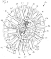
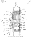
- Die Erfindung wird nachfolgend anhand eines bevorzugten Ausführungsbeispiels weiter beschrieben, welches schematisch in den Zeichnungen dargestellt ist. In den Zeichnungen zeigen:
- Fig.1
- eine perspektivische Ansicht einer erfindungsgemäßen Windenvorrichtung von hinten;
- Fig. 2
- eine perspektivische Ansicht der Windenvorrichtung von
Fig.1 mit weiteren Details von vorne und - Fig. 3
- eine Querschnittsdarstellung durch die Windenvorrichtung von
Fig. 1 . - Mit Bezug auf die
Figuren 1 bis 3 umfasst eine erfindungsgemäße Windenvorrichtung 10 eine lagerbockartige Halterung 12, an welcher eine scheibenförmige Anschlussplatte 14 fest angebracht ist. An der Anschlussplatte 14 ist eine ringförmige Drehlagerung 16 angeordnet, mit welcher eine Windentrommel 20 freitragend und drehbar um eine Drehachse 17 gelagert ist. - Die Windentrommel 20 weist einen trommelförmigen Grundkörper 22 auf, an dessen axialen Enden Scheibenwände 24 radial nach außen vorstehen, um einen Aufnahmebereich zum Aufnehmen von Windungen einer Leitung 30 zu bilden, welche als Leitungsbündel dargestellt ist. In den Seitenwänden 24 können Ausnehmungen 25 ausgebildet sein, wie in
Fig. 3 darstellt ist. Das Leitungsbündel kann aus mehreren Schlauch-, Signal- oder Elektroleitungen zusammengesetzt sein. An einem Seitenbereich des trommelförmigen Grundkörpers 22 ist eine scheibenförmige Nabe 26 ausgebildet, welche mit der Drehlagerung 16 in Verbindung steht. - In einem hohlen Nabenbereich 28, welcher durch den trommelförmigen Grundkörper 22 umschlossen ist, sind exzentrisch zur Drehachse 17 an der Nabe 26 der Windentrommel 20 zwei innere Drehantriebe 40 befestigt. An der Nabe 26 ist hierzu ein Befestigungsflansch 27 ausgebildet.
- Wie schematisch in
Fig. 2 angedeutet ist, weist jeder Drehantrieb 40 eine Antriebsachse 44 auf, um welche ein Antriebsritzel 42 mit einer Außenverzahnung drehend angetrieben wird. Die Antriebsachse 44 ist parallel zur Drehachse 17. Das Antriebsritzel 42 kämmt mit einem Zahnkranz 18 mit einer korrespondierenden Innenverzahnung, wobei der Zahnkranz 18 an der Anschlussplatte 14 der Halterung 12 befestigt ist. Durch das kämmende Eingreifen des Antriebsritzels 42 läuft dieses planetenartig entlang des Zahnkranzes 18 um die Drehachse 17 um, wobei die Windentrommel 20 in eine entsprechende Drehbewegung um die Drehachse 17 versetzt wird. - Konzentrisch zur Drehachse 17 ist eine schaftartige Drehdurchführung 50 angeordnet. Die Drehdurchführung 50 weist dabei einen schematisch angedeuteten Stator 52 auf, welcher drehfest mit der Anschlussplatte 14 und so mit der Halterung 12 verbunden ist. An dem Stator 52 sind Zuführleitungen 32 zum Zuführen und/oder Abführen eines oder mehrerer Fluide zu bzw. von den Leitungen 30 angeschlossen.
- Die Drehdurchführung 50 weist weiter einen Rotor 54 auf, welcher relativ drehbar zu dem Stator 52 der Drehdurchführung 50 ist. Der Rotor 54 ist fest mit der Nabe 26 der Windentrommel 20 verbunden und dreht sich mit dieser. Die Leitungen 30 auf der Windentrommel 20 können über Leitungsanschlüsse 31 mit korrespondierenden Anschlüssen 56 des Rotors 54 verbunden sein. Auf diese Weise kann Fluid von den Zuführleitungen 32 über die Drehdurchführung 50 auf die Leitungen 30 auf der Windentrommel 20 übertragen werden.
- Neben der Übertragung eines oder mehrere Fluide, elektrischer Energie oder von Signalen für das Leitungsbündel kann über die Drehdurchführung 50 auch Energie zu dem Drehantrieb 40 über eine schematisch dargestellte Energiezuführung 46 erfolgen. Als Energie kann insbesondere Hydraulikfluid oder elektrischer Strom über die Drehdurchführung 50 von außen an den umlaufenden Drehantrieb 40 übertragen werden.
- Durch die erfindungsgemäße Anordnung können in einfacher Weise die Schlauch- oder Elektroleitungen als Leitungen 30 auf der Windentrommel 20 mit dem Rotor 54 der Drehdurchführung 50 verbunden werden, so dass nicht nur Fluid von außen über die Drehdurchführung 50 an das Leitungsbündel übertragen werden kann. Durch den innenliegenden Drehantrieb 40 an der Windentrommel 20 kann eine besonders kompakte Bauform der Windenvorrichtung 10 erreicht werden.
Claims (11)
- Windenvorrichtung, insbesondere für eine Baugeräteanordnung, mit- einer Windentrommel (20),- einer Halterung (12), an welcher die Windentrommel (20) über eine Drehlagerung (16) drehbar um eine Drehachse (17) gelagert ist, und- mindestens einem Drehantrieb (40), mit welchem die Windentrommel (20) drehend antreibbar ist,dadurch gekennzeichnet,- dass der mindestens eine Drehantrieb (40) an der Windentrommel (20) angebracht ist, wobei der Drehantrieb (40) mit der Windentrommel (20) um die Drehachse (17) drehbar ist.
- Windenvorrichtung nach Anspruch 1,
dadurch gekennzeichnet,
dass eine Energieübertragungseinrichtung vorgesehen ist, mit welcher Energie von der feststehenden Halterung (12) zu dem mindestens einen Drehantrieb (40) an der Windentrommel (20) übertragbar ist. - Windenvorrichtung nach Anspruch 1 oder 2,
dadurch gekennzeichnet,
dass der mindestens eine Drehantrieb (40) ein Hydraulikmotor oder ein Elektromotor ist. - Windenvorrichtung nach einem der Ansprüche 1 bis 3,
dadurch gekennzeichnet,
dass die Windentrommel (20) einen hohlen Nabenbereich (28) aufweist und dass der mindestens eine Drehantrieb (40) in dem hohlen Nabenbereich (28) angeordnet ist. - Windenvorrichtung nach einem der Ansprüche 1 bis 4,
dadurch gekennzeichnet,
dass die Windentrommel (20) als eine Leitungstrommel mit mindestens einer Leitung (30) oder einem Leitungsbündel zum Leiten eines Fluids, von Signalen und/oder elektrischem Strom ausgebildet ist und
dass an der Leitungstrommel, insbesondere in einem Nabenbereich (28), mindestens ein Anschluss zum Anschließen der mindestens einen Leitung (30) bzw. des Leitungsbündels ausgebildet ist. - Windenvorrichtung nach Anspruch 5,
dadurch gekennzeichnet,
dass an der Drehlagerung (16) eine Drehdurchführung (50) für mindestens ein Fluid und oder mindestens eine Signalleitung und/oder elektrischen Strom angeordnet ist, welche einen Stator (52), welcher an der Halterung (12) drehfest angebracht ist, und einen relativ dazu drehbaren Rotor (54) aufweist, welcher fest mit der Windentrommel (20) verbunden ist, und
dass durch die Drehdurchführung (50) eine Fluidverbindung, eine Signalverbindung und/oder eine elektrische Verbindung zwischen der Halterung (12) und der Leitung (30) der Leitungstrommel gebildet ist. - Windenvorrichtung nach einem der Ansprüche 1 bis 6,
dadurch gekennzeichnet,
dass der mindestens eine Drehantrieb (40) eine Antriebswelle mit einem Antriebsritzel (42) aufweist und
dass das Antriebsritzel (42) mit einem ringförmigen Zahnkranz (18) in kämmender Verbindung steht, welcher an der Halterung (12) konzentrisch zur Drehachse (17) angeordnet ist. - Windenvorrichtung nach einem der Ansprüche 1 bis 7,
dadurch gekennzeichnet,
dass der mindestens eine Drehantrieb (40) exzentrisch an der Windentrommel (20) angeordnet ist. - Windenvorrichtung nach einem der Ansprüche 1 bis 8,
dadurch gekennzeichnet,
dass zwei Drehantriebe (40) in einem Nabenbereich (28) der Windentrommel (20) angeordnet sind. - Baugeräteanordnung mit mindestens einem Baugerät,
dadurch gekennzeichnet,
dass mindestens eine Windenvorrichtung (10) nach einem der Ansprüche 1 bis 9 vorgesehen ist. - Baugeräteanordnung nach Anspruch 10,
dadurch gekennzeichnet,
dass ein Tiefbaugerät, insbesondere eine Schlitzwandfräse, vorgesehen ist.
Priority Applications (4)
| Application Number | Priority Date | Filing Date | Title |
|---|---|---|---|
| EP21167443.7A EP4071100B1 (de) | 2021-04-08 | 2021-04-08 | Windenvorrichtung, insbesondere für eine baugeräteanordnung |
| CN202210338553.2A CN115196434B (zh) | 2021-04-08 | 2022-04-01 | 绞盘装置、特别是用于施工装置组件的绞盘装置 |
| KR1020220040956A KR102856360B1 (ko) | 2021-04-08 | 2022-04-01 | 건설 장치 어셈블리를 위한 윈치 장치 |
| JP2022063216A JP7300537B2 (ja) | 2021-04-08 | 2022-04-06 | ウィンチ装置、とりわけ建設装置アセンブリ用のウィンチ装置 |
Applications Claiming Priority (1)
| Application Number | Priority Date | Filing Date | Title |
|---|---|---|---|
| EP21167443.7A EP4071100B1 (de) | 2021-04-08 | 2021-04-08 | Windenvorrichtung, insbesondere für eine baugeräteanordnung |
Publications (3)
| Publication Number | Publication Date |
|---|---|
| EP4071100A1 true EP4071100A1 (de) | 2022-10-12 |
| EP4071100B1 EP4071100B1 (de) | 2024-10-23 |
| EP4071100C0 EP4071100C0 (de) | 2024-10-23 |
Family
ID=75438649
Family Applications (1)
| Application Number | Title | Priority Date | Filing Date |
|---|---|---|---|
| EP21167443.7A Active EP4071100B1 (de) | 2021-04-08 | 2021-04-08 | Windenvorrichtung, insbesondere für eine baugeräteanordnung |
Country Status (4)
| Country | Link |
|---|---|
| EP (1) | EP4071100B1 (de) |
| JP (1) | JP7300537B2 (de) |
| KR (1) | KR102856360B1 (de) |
| CN (1) | CN115196434B (de) |
Families Citing this family (3)
| Publication number | Priority date | Publication date | Assignee | Title |
|---|---|---|---|---|
| CN117963643B (zh) * | 2024-03-29 | 2024-05-28 | 国网山东省电力公司利津县供电公司 | 一种电力布线机构 |
| KR102783569B1 (ko) * | 2024-04-25 | 2025-03-26 | 동일산업(주) | 동력전달용 릴 권취장치 |
| KR102830542B1 (ko) * | 2024-09-25 | 2025-07-08 | 주식회사 다모다 | 발전기 회전자 인출입 장치용 트래버스 캠을 이용한 윈치 장치 |
Citations (4)
| Publication number | Priority date | Publication date | Assignee | Title |
|---|---|---|---|---|
| DE29716078U1 (de) * | 1997-09-06 | 1997-11-27 | Niehüser, Hermann, Dipl.-Ing., 33449 Langenberg | Schlauchtrommel |
| DE19842081A1 (de) * | 1998-08-29 | 2000-03-16 | Hermann Niehueser | Schlauchtrommel |
| DE19840831A1 (de) * | 1998-09-07 | 2000-03-16 | Volker U Schmidt | Tragbare Aufrollanordnung mit Eigenantrieb, insbesondere für Kabel und Schläuche |
| EP3425123A1 (de) | 2017-07-06 | 2019-01-09 | BAUER Maschinen GmbH | Ausleger für eine baumaschine |
Family Cites Families (11)
| Publication number | Priority date | Publication date | Assignee | Title |
|---|---|---|---|---|
| DE3365920D1 (en) * | 1982-12-27 | 1986-10-09 | Frode Andersen | A capstan winch, particularly for sailing boats |
| JP2002226143A (ja) * | 2001-01-26 | 2002-08-14 | Arata:Kk | 電動コードリール |
| ES2339961T3 (es) * | 2006-08-31 | 2010-05-27 | ROTZLER GMBH & CO. KG | Torno de cable. |
| JP2008247583A (ja) * | 2007-03-30 | 2008-10-16 | Ihi Corp | クレーン用ウインチ装置 |
| ATE432910T1 (de) | 2007-11-28 | 2009-06-15 | Bauer Maschinen Gmbh | Winde |
| NO334466B1 (no) | 2010-04-27 | 2014-03-10 | Fobox As | En drivanordning |
| KR101194565B1 (ko) | 2010-08-27 | 2012-10-25 | 삼성중공업 주식회사 | 케이블을 이용한 이송장치용 윈치 |
| KR20140140333A (ko) * | 2013-05-29 | 2014-12-09 | 바다중공업 주식회사 | 선박용 윈치 |
| WO2015077822A1 (en) * | 2013-11-27 | 2015-06-04 | Stress Free Marine Pty Ltd | An improved winch assembly and towrope guide assembly |
| JP6404694B2 (ja) * | 2014-12-05 | 2018-10-10 | 株式会社神戸製鋼所 | 電動ウインチ装置及び移動式クレーン |
| KR102328052B1 (ko) * | 2016-05-23 | 2021-11-17 | 바덱스 코퍼레이션 | 회전식 체인 스토퍼 |
-
2021
- 2021-04-08 EP EP21167443.7A patent/EP4071100B1/de active Active
-
2022
- 2022-04-01 KR KR1020220040956A patent/KR102856360B1/ko active Active
- 2022-04-01 CN CN202210338553.2A patent/CN115196434B/zh active Active
- 2022-04-06 JP JP2022063216A patent/JP7300537B2/ja active Active
Patent Citations (4)
| Publication number | Priority date | Publication date | Assignee | Title |
|---|---|---|---|---|
| DE29716078U1 (de) * | 1997-09-06 | 1997-11-27 | Niehüser, Hermann, Dipl.-Ing., 33449 Langenberg | Schlauchtrommel |
| DE19842081A1 (de) * | 1998-08-29 | 2000-03-16 | Hermann Niehueser | Schlauchtrommel |
| DE19840831A1 (de) * | 1998-09-07 | 2000-03-16 | Volker U Schmidt | Tragbare Aufrollanordnung mit Eigenantrieb, insbesondere für Kabel und Schläuche |
| EP3425123A1 (de) | 2017-07-06 | 2019-01-09 | BAUER Maschinen GmbH | Ausleger für eine baumaschine |
Also Published As
| Publication number | Publication date |
|---|---|
| JP7300537B2 (ja) | 2023-06-29 |
| CN115196434A (zh) | 2022-10-18 |
| KR102856360B1 (ko) | 2025-09-04 |
| EP4071100B1 (de) | 2024-10-23 |
| CN115196434B (zh) | 2026-01-02 |
| JP2022161873A (ja) | 2022-10-21 |
| EP4071100C0 (de) | 2024-10-23 |
| KR20220139798A (ko) | 2022-10-17 |
Similar Documents
| Publication | Publication Date | Title |
|---|---|---|
| EP4071100B1 (de) | Windenvorrichtung, insbesondere für eine baugeräteanordnung | |
| EP1250748B1 (de) | Elektrischer antrieb für ein fahrzeug | |
| EP2287053B1 (de) | Vorrichtung zur Reinigung von Fahrzeugrädern | |
| EP1170096B1 (de) | Kombiniertes Elektrohandwerkzeuggerät | |
| DE8214938U1 (de) | Gelenkkopf für Industrieroboter | |
| DE3732811A1 (de) | Drehkraft-uebertragungsvorrichtung fuer ein fahrzeug mit vierradantrieb | |
| EP2331299B1 (de) | Handwerkzeugmaschine mit einer spindel zur aufnahme eines werkzeugs | |
| EP0674122A2 (de) | Getriebemotor | |
| DE19645650C1 (de) | Gesteinsfräskopf | |
| DE1634871C3 (de) | eine lotrechte Achse drehbaren Drehtisches einer schweren Baumaschine, wie Bagger, Kran o.dgl | |
| DE202007002403U1 (de) | Antrieb für die Grabtrommel eines Tagebaugewinnungsgerätes | |
| DE102004005869A1 (de) | Antriebseinheit, insbesondere Einrad-Triebwerk für ein batteriebetriebenes Fahrzeug | |
| DE3444420A1 (de) | Vorrichtung zur erzeugung von schwenkbewegungen | |
| EP4402084B1 (de) | Trommelanordnung | |
| WO2008037618A1 (de) | Mehrstufiges untersetzungsgetriebe | |
| EP3368799A1 (de) | Schaltvorrichtung und antriebseinheit für ein kraftfahrzeug | |
| DE3137101C2 (de) | ||
| EP3752713A1 (de) | Walzenschrämlader sowie eine schrämwalze eines walzenschrämladers | |
| DE102019131782A1 (de) | Motor-Leitungstrommelanordnung oder Motor-Schlauch-Trommelanordnung | |
| DE102016212818A1 (de) | Lenkung für Fahrzeuge mit Hochübersetzungsgetriebe, insbesondere für Nutzkraftfahrzeuge | |
| EP0676560A2 (de) | Wolfrom-Planetengetriebe mit einem angetriebenen Umlaufträger | |
| DE102007038264A1 (de) | Aktiver Stabilisator zur Wankstabilisierung | |
| DE2023982A1 (de) | ||
| EP2329896A1 (de) | Vorrichtung zum kontinuierlichen Wellen eines metallischen Rohres | |
| DE617052C (de) | Vorrichtung, um zwei zentrisch gelagerte, mit gleicher Drehzahl und im gleichen Drehsinn umlaufende Wellen gegeneinander zu verstellen |
Legal Events
| Date | Code | Title | Description |
|---|---|---|---|
| PUAI | Public reference made under article 153(3) epc to a published international application that has entered the european phase |
Free format text: ORIGINAL CODE: 0009012 |
|
| STAA | Information on the status of an ep patent application or granted ep patent |
Free format text: STATUS: THE APPLICATION HAS BEEN PUBLISHED |
|
| AK | Designated contracting states |
Kind code of ref document: A1 Designated state(s): AL AT BE BG CH CY CZ DE DK EE ES FI FR GB GR HR HU IE IS IT LI LT LU LV MC MK MT NL NO PL PT RO RS SE SI SK SM TR |
|
| STAA | Information on the status of an ep patent application or granted ep patent |
Free format text: STATUS: REQUEST FOR EXAMINATION WAS MADE |
|
| 17P | Request for examination filed |
Effective date: 20230224 |
|
| RBV | Designated contracting states (corrected) |
Designated state(s): AL AT BE BG CH CY CZ DE DK EE ES FI FR GB GR HR HU IE IS IT LI LT LU LV MC MK MT NL NO PL PT RO RS SE SI SK SM TR |
|
| GRAP | Despatch of communication of intention to grant a patent |
Free format text: ORIGINAL CODE: EPIDOSNIGR1 |
|
| STAA | Information on the status of an ep patent application or granted ep patent |
Free format text: STATUS: GRANT OF PATENT IS INTENDED |
|
| INTG | Intention to grant announced |
Effective date: 20240710 |
|
| GRAS | Grant fee paid |
Free format text: ORIGINAL CODE: EPIDOSNIGR3 |
|
| GRAA | (expected) grant |
Free format text: ORIGINAL CODE: 0009210 |
|
| STAA | Information on the status of an ep patent application or granted ep patent |
Free format text: STATUS: THE PATENT HAS BEEN GRANTED |
|
| AK | Designated contracting states |
Kind code of ref document: B1 Designated state(s): AL AT BE BG CH CY CZ DE DK EE ES FI FR GB GR HR HU IE IS IT LI LT LU LV MC MK MT NL NO PL PT RO RS SE SI SK SM TR |
|
| REG | Reference to a national code |
Ref country code: GB Ref legal event code: FG4D Free format text: NOT ENGLISH |
|
| REG | Reference to a national code |
Ref country code: CH Ref legal event code: EP |
|
| REG | Reference to a national code |
Ref country code: DE Ref legal event code: R096 Ref document number: 502021005542 Country of ref document: DE |
|
| REG | Reference to a national code |
Ref country code: IE Ref legal event code: FG4D Free format text: LANGUAGE OF EP DOCUMENT: GERMAN |
|
| U01 | Request for unitary effect filed |
Effective date: 20241104 |
|
| U07 | Unitary effect registered |
Designated state(s): AT BE BG DE DK EE FI FR IT LT LU LV MT NL PT RO SE SI Effective date: 20241114 |
|
| PG25 | Lapsed in a contracting state [announced via postgrant information from national office to epo] |
Ref country code: IS Free format text: LAPSE BECAUSE OF FAILURE TO SUBMIT A TRANSLATION OF THE DESCRIPTION OR TO PAY THE FEE WITHIN THE PRESCRIBED TIME-LIMIT Effective date: 20250223 Ref country code: HR Free format text: LAPSE BECAUSE OF FAILURE TO SUBMIT A TRANSLATION OF THE DESCRIPTION OR TO PAY THE FEE WITHIN THE PRESCRIBED TIME-LIMIT Effective date: 20241023 |
|
| PG25 | Lapsed in a contracting state [announced via postgrant information from national office to epo] |
Ref country code: ES Free format text: LAPSE BECAUSE OF FAILURE TO SUBMIT A TRANSLATION OF THE DESCRIPTION OR TO PAY THE FEE WITHIN THE PRESCRIBED TIME-LIMIT Effective date: 20241023 |
|
| PG25 | Lapsed in a contracting state [announced via postgrant information from national office to epo] |
Ref country code: NO Free format text: LAPSE BECAUSE OF FAILURE TO SUBMIT A TRANSLATION OF THE DESCRIPTION OR TO PAY THE FEE WITHIN THE PRESCRIBED TIME-LIMIT Effective date: 20250123 |
|
| PG25 | Lapsed in a contracting state [announced via postgrant information from national office to epo] |
Ref country code: GR Free format text: LAPSE BECAUSE OF FAILURE TO SUBMIT A TRANSLATION OF THE DESCRIPTION OR TO PAY THE FEE WITHIN THE PRESCRIBED TIME-LIMIT Effective date: 20250124 |
|
| PG25 | Lapsed in a contracting state [announced via postgrant information from national office to epo] |
Ref country code: PL Free format text: LAPSE BECAUSE OF FAILURE TO SUBMIT A TRANSLATION OF THE DESCRIPTION OR TO PAY THE FEE WITHIN THE PRESCRIBED TIME-LIMIT Effective date: 20241023 |
|
| PG25 | Lapsed in a contracting state [announced via postgrant information from national office to epo] |
Ref country code: RS Free format text: LAPSE BECAUSE OF FAILURE TO SUBMIT A TRANSLATION OF THE DESCRIPTION OR TO PAY THE FEE WITHIN THE PRESCRIBED TIME-LIMIT Effective date: 20250123 |
|
| U20 | Renewal fee for the european patent with unitary effect paid |
Year of fee payment: 5 Effective date: 20250425 |
|
| PG25 | Lapsed in a contracting state [announced via postgrant information from national office to epo] |
Ref country code: SM Free format text: LAPSE BECAUSE OF FAILURE TO SUBMIT A TRANSLATION OF THE DESCRIPTION OR TO PAY THE FEE WITHIN THE PRESCRIBED TIME-LIMIT Effective date: 20241023 |
|
| PG25 | Lapsed in a contracting state [announced via postgrant information from national office to epo] |
Ref country code: SK Free format text: LAPSE BECAUSE OF FAILURE TO SUBMIT A TRANSLATION OF THE DESCRIPTION OR TO PAY THE FEE WITHIN THE PRESCRIBED TIME-LIMIT Effective date: 20241023 |
|
| PG25 | Lapsed in a contracting state [announced via postgrant information from national office to epo] |
Ref country code: CZ Free format text: LAPSE BECAUSE OF FAILURE TO SUBMIT A TRANSLATION OF THE DESCRIPTION OR TO PAY THE FEE WITHIN THE PRESCRIBED TIME-LIMIT Effective date: 20241023 |
|
| PLBE | No opposition filed within time limit |
Free format text: ORIGINAL CODE: 0009261 |
|
| STAA | Information on the status of an ep patent application or granted ep patent |
Free format text: STATUS: NO OPPOSITION FILED WITHIN TIME LIMIT |
|
| 26N | No opposition filed |
Effective date: 20250724 |
|
| REG | Reference to a national code |
Ref country code: CH Ref legal event code: H13 Free format text: ST27 STATUS EVENT CODE: U-0-0-H10-H13 (AS PROVIDED BY THE NATIONAL OFFICE) Effective date: 20251125 |
|
| PG25 | Lapsed in a contracting state [announced via postgrant information from national office to epo] |
Ref country code: MC Free format text: LAPSE BECAUSE OF FAILURE TO SUBMIT A TRANSLATION OF THE DESCRIPTION OR TO PAY THE FEE WITHIN THE PRESCRIBED TIME-LIMIT Effective date: 20241023 |
|
| GBPC | Gb: european patent ceased through non-payment of renewal fee |
Effective date: 20250408 |
|
| PG25 | Lapsed in a contracting state [announced via postgrant information from national office to epo] |
Ref country code: GB Free format text: LAPSE BECAUSE OF NON-PAYMENT OF DUE FEES Effective date: 20250408 |
|
| PG25 | Lapsed in a contracting state [announced via postgrant information from national office to epo] |
Ref country code: CH Free format text: LAPSE BECAUSE OF NON-PAYMENT OF DUE FEES Effective date: 20250430 |
|
| PG25 | Lapsed in a contracting state [announced via postgrant information from national office to epo] |
Ref country code: IE Free format text: LAPSE BECAUSE OF NON-PAYMENT OF DUE FEES Effective date: 20250408 |
|
| U20 | Renewal fee for the european patent with unitary effect paid |
Year of fee payment: 6 Effective date: 20260414 |
|
| PG25 | Lapsed in a contracting state [announced via postgrant information from national office to epo] |
Ref country code: CY Free format text: LAPSE BECAUSE OF FAILURE TO SUBMIT A TRANSLATION OF THE DESCRIPTION OR TO PAY THE FEE WITHIN THE PRESCRIBED TIME-LIMIT Effective date: 20241023 |