EP4069817B1 - Verbesserte methanisierungseinheit - Google Patents
Verbesserte methanisierungseinheit Download PDFInfo
- Publication number
- EP4069817B1 EP4069817B1 EP20808115.8A EP20808115A EP4069817B1 EP 4069817 B1 EP4069817 B1 EP 4069817B1 EP 20808115 A EP20808115 A EP 20808115A EP 4069817 B1 EP4069817 B1 EP 4069817B1
- Authority
- EP
- European Patent Office
- Prior art keywords
- filter
- biomass
- leachate
- methanisation
- percolat
- Prior art date
- Legal status (The legal status is an assumption and is not a legal conclusion. Google has not performed a legal analysis and makes no representation as to the accuracy of the status listed.)
- Active
Links
Images

Classifications
-
- C—CHEMISTRY; METALLURGY
- C12—BIOCHEMISTRY; BEER; SPIRITS; WINE; VINEGAR; MICROBIOLOGY; ENZYMOLOGY; MUTATION OR GENETIC ENGINEERING
- C12M—APPARATUS FOR ENZYMOLOGY OR MICROBIOLOGY; APPARATUS FOR CULTURING MICROORGANISMS FOR PRODUCING BIOMASS, FOR GROWING CELLS OR FOR OBTAINING FERMENTATION OR METABOLIC PRODUCTS, i.e. BIOREACTORS OR FERMENTERS
- C12M21/00—Bioreactors or fermenters specially adapted for specific uses
- C12M21/04—Bioreactors or fermenters specially adapted for specific uses for producing gas, e.g. biogas
-
- C—CHEMISTRY; METALLURGY
- C12—BIOCHEMISTRY; BEER; SPIRITS; WINE; VINEGAR; MICROBIOLOGY; ENZYMOLOGY; MUTATION OR GENETIC ENGINEERING
- C12M—APPARATUS FOR ENZYMOLOGY OR MICROBIOLOGY; APPARATUS FOR CULTURING MICROORGANISMS FOR PRODUCING BIOMASS, FOR GROWING CELLS OR FOR OBTAINING FERMENTATION OR METABOLIC PRODUCTS, i.e. BIOREACTORS OR FERMENTERS
- C12M29/00—Means for introduction, extraction or recirculation of materials, e.g. pumps
- C12M29/02—Percolation
-
- C—CHEMISTRY; METALLURGY
- C12—BIOCHEMISTRY; BEER; SPIRITS; WINE; VINEGAR; MICROBIOLOGY; ENZYMOLOGY; MUTATION OR GENETIC ENGINEERING
- C12M—APPARATUS FOR ENZYMOLOGY OR MICROBIOLOGY; APPARATUS FOR CULTURING MICROORGANISMS FOR PRODUCING BIOMASS, FOR GROWING CELLS OR FOR OBTAINING FERMENTATION OR METABOLIC PRODUCTS, i.e. BIOREACTORS OR FERMENTERS
- C12M29/00—Means for introduction, extraction or recirculation of materials, e.g. pumps
- C12M29/04—Filters; Permeable or porous membranes or plates, e.g. dialysis
-
- Y—GENERAL TAGGING OF NEW TECHNOLOGICAL DEVELOPMENTS; GENERAL TAGGING OF CROSS-SECTIONAL TECHNOLOGIES SPANNING OVER SEVERAL SECTIONS OF THE IPC; TECHNICAL SUBJECTS COVERED BY FORMER USPC CROSS-REFERENCE ART COLLECTIONS [XRACs] AND DIGESTS
- Y02—TECHNOLOGIES OR APPLICATIONS FOR MITIGATION OR ADAPTATION AGAINST CLIMATE CHANGE
- Y02E—REDUCTION OF GREENHOUSE GAS [GHG] EMISSIONS, RELATED TO ENERGY GENERATION, TRANSMISSION OR DISTRIBUTION
- Y02E50/00—Technologies for the production of fuel of non-fossil origin
- Y02E50/30—Fuel from waste, e.g. synthetic alcohol or diesel
Definitions
- the present invention lies in the field of gas production from organic materials. It concerns more particularly a methanization unit.
- Anaerobic digestion is the natural biological process of degradation of organic matter in the absence of oxygen. This degradation produces biogas, which can be used as an energy source.
- Batch dry methanization is a method in which a methanization chamber is loaded with biomass. Methanization then takes place. When the methanization is completed, the chamber is unloaded from the biomass residues not transformed into biogas, before starting again.
- the use of several chambers in parallel allows continuous production of biogas.
- percolate When part of the percolation liquid has completely passed through the biomass, a liquid called percolate accumulates at the bottom of the methanization chamber. This liquid is composed of the part of the percolation liquid which has not remained in the biomass, and certain fine particles of the biomass carried away by this liquid. Percolate accumulation often takes place in front of or behind the biomass. It is then desirable to remove the percolat from the methanization chamber, so as not to increase the pressure on the walls of the chamber. In addition, the exit of the percolat from the chamber makes it possible to recover a liquid loaded with bacteria which can be reused for percolation.
- WO2007096392 presents a discontinuous dry process biogas production unit.
- the floor is inclined in order to drain the percolate towards one end of the methanization chamber. At this end there is a grid allowing the percola to be collected in a channel, which leads to a percola tank.
- EP1428868 discloses a dry methanization unit with a percolation system comprising a filter for collecting the percolate under the biomass to be fermented.
- An object of the present invention is to propose a batch dry methanization unit allowing more rapid methanization of biomass.
- the present invention aims to respond at least in part to the aforementioned objects by proposing a more efficient methanization unit, with a more reliable flow of the percolat.
- a discontinuous dry methanization unit comprising a loading space intended to accommodate biomass to be methanized, the methanization unit comprising a percolation means, and a means for evacuating a percolate, in which:
- the second filter is protected by the first filter, and the percolate flows better through the second filter.
- a stage of circulation of the percolat is also added in a circulation space between the stages of filtration of the percolat by the first filter and by the second filter; such a characteristic makes it possible to optimize the flow of the percolat, which is present at the inlet of the second filter over its entire surface, and thus guarantees better use of said second filter; preferably, a stage of circulation of the percolat is added in a second circulation space between the stages of filtration of the percolat by the second filter and the stage of evacuation of the percolat, also making it possible to optimize the flow of percolat at the outlet of the second filter, and avoiding forcing the percolat to circulate transversely in the second filter to reach the evacuation means.
- the methanization unit according to the invention was designed for batch dry methanization.
- the methanization unit has a loading space 1 intended to accommodate biomass 2.
- Biomass 2 can include green waste such as green plants, branches, manure, slurry, or even any biomass usually used to produce biogas.
- the methanization unit comprises a percolation means 3, making it possible to spread a percolation liquid 4, for example slurry, on top of the biomass 2.
- This percolation liquid 4 passes through the biomass, and can be loaded with various particles on this occasion. We will call percolat 5 the charged liquid obtained.
- the methanization unit also includes a means 6 for evacuating the percolat 5.
- the methanization unit comprises a first filter 7, arranged so as to separate the loading space 1 from a circulation space 8, the circulation space 8 being located between the first filter 7 and the evacuation means 6.
- This allows the percolat 5 to circulate freely once it has left the biomass 2, and up to the evacuation means 6.
- the evacuation means 6 may consist of an opening in the section of a pipe, placed in a corner of the methanization unit.
- the first filter 7 may have the shape of a spherical cap, arranged around this corner. A distance is thus created between the biomass 2 and the evacuation means 6, which allows the percolat 5 to circulate freely.
- the methanization unit comprises a second filter 9, arranged between the circulation space and the evacuation means 6.
- This second filter 9 can be placed directly on the evacuation means 6. But it can also be arranged so to provide a second circulation space 10, allowing the percolat 5 to circulate freely between the outlet of the second filter 9 and the evacuation means 6.
- Such a configuration makes it possible to have a second filter 9 with a section much larger than the section of the evacuation means 6, and thus improve the filtration speed, and/or increase the duration of use of the second filter 9 between two cleanings.
- the methanization unit is of parallelepiped shape, preferably rectangular, and comprises a front wall 11, a rear wall 12, two side walls 13a, 13b, a floor 14 and a ceiling 15.
- front designates the direction towards the front wall 11 of the methanization unit.
- rear designates the direction towards the rear wall 4 of the methanization unit.
- the floor 14 preferably includes a slope 16 descending towards the rear wall 12.
- the slope 16 can extend over the entire floor 14, or over only part of the floor 14. The slope 16 makes it possible to direct the percolate 5 towards a means of evacuation 6 of the percolat out of the methanization unit.
- the first filter 7 is arranged such that it is between the biomass 2, placed in the loading space 1, and the circulation space 8. According to a preferred embodiment of the invention, the first filter 7 can for example extend on the floor 14 from one side wall 13a to the other 13b.
- the second filter 9 is arranged such that it is located between the circulation space 8 and the evacuation means 6.
- the second filter 9 can for example extend on the floor 14, parallel and to the rear of the first filter 7.
- the term "on the ground” is not limited to a filter entirely placed on the ground, and that a filter part of which would be placed under the plane formed by the ground 14, is covered by this expression, as long as the filter is capable of filtering the percolat 5 flowing onto the ground.
- the floor 14 can be entirely planar, but it can also include recesses such as grooves.
- a filter 7, 9 placed in a groove in the floor is considered in the present invention as a filter placed on the floor.
- the second filter 9 is finer than the first filter 7, that is to say that the second filter 9 is such that it does not let certain elements pass that the first filter 7 lets pass.
- the first filter 7 is for example configured to allow only the liquid and the elements of which at least one dimension is less than a coarse dimension to pass, said coarse dimension being between 10 and 80 mm, depending on the products constituting the biomass 2.
- this comprises a plurality of elongated elements, for example made of plastic, wood or metal, arranged parallel to each other, resting on one side on the ground 14 and the other side on the rear wall 12 of the loading space 1.
- the elongated elements can thus be arranged at an angle of between 30 and 60°, typically an angle of 45° relative to the horizontal.
- Another possible embodiment is a metal grid, for example vertical.
- the second filter 9 is for example configured to allow only the liquid and the elements of which at least two dimensions are less than a fine dimension to pass, the fine dimension being between 1 and 10 mm.
- this can be produced by a mesh envelope, for example made of a sheet pierced with holes of 5 to 10 mm in diameter, in which filter elements such as filter elements are placed. stones or plastic parts.
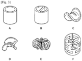
- the plastic elements can be balls, rings, or even tubes of different shapes, and dimensions varying from typically 25 to 50 mm. Different types of bulk packing may be suitable, some examples of which are shown in [ Fig.3 ].
- the first filter 7 and the second filter 9 are preferably placed so as to provide a circulation space 8 between the two.
- the percolat 5 leaving the first filter 7 can freely extend into the circulation space 8, and thus not accumulate in front of only part of the second filter 9.
- This arrangement makes it possible to optimize the use of the entire capacity of the second filter 9, and thus makes it possible to accelerate the filtration of the percolat 5 by the second filter 9.
- the flow space can for example extend to the ground over a distance greater than 10 cm.
- the second filter 9 can be arranged so as to provide a second circulation space 10 between said second filter 9 and the evacuation means 6.
- the evacuation means 6 may consist of one or more openings arranged in the edge between the rear wall and the ground, of the section of a pipe, for example with a diameter of 10 cm.
- the second filter 9 can be arranged over the entire width of the methanization unit, in this same edge, from one side wall 13a to the other 13b.
- a second circulation space 10 is provided between the second filter 9 and the evacuation means 6, for example by a channel, of height for example 5 to 10 cm, of width slightly less than the width of the second filter 9, just to maintain a support at ground level for said second filter, or even of the same width as the second filter 9, and the latter is partially inserted into the channel, leaving a space with the bottom of the channel.
- a second circulation space 10 all along the edge, and the percolat can pass through the second filter 9 vertically, exit the second filter by flowing downwards, then circulate freely towards one of the openings of the means of evacuation 6.
- the channel 17 can consist of a pipe open at the front and at the rear, through which the percolat 5 can circulate. You can place a filter at the entrance before pipe, to avoid blocking the entrance to the pipe by the biomass 2.
- two channels 17 can be arranged, one along each side wall 13a and 13b.
- the longitudinal channel 17 can also consist of a perforated pipe, the perforations allowing the percolat 5 to enter the pipe over the entire length of the loading space 1, without the biomass entering there.
- the risk of blocking the perforations can be reduced by placing a filter between the biomass 2 and the channel 17 over its entire length.
- the perforated pipe 17 can also be opened at the front to recover the excess percolate 5 having flowed towards the front.
- a wall 18 to protect the front wall, the function of which is to prevent the biomass from coming to rest on the front wall 11.
- the wall can be permeable to the percolate or we can have holes there. , to allow the percolat 5 to pass, which can then flow through the longitudinal channel(s) 17.
- the wall 18 also makes it possible to prevent the biomass 2 and the percolat from resting on the front wall of the processing unit. methanization and generate too much pressure.
- This allows the percolat 5 to circulate freely between the outlet of the second filter 9 and the evacuation means 6, and thus allows the percolat 5 to pass through said second filter 9 along a shortest crossing path, by not forcing the percolat 5 to travel a longitudinal or transverse path inside the second filter 9 .
Landscapes
- Life Sciences & Earth Sciences (AREA)
- Health & Medical Sciences (AREA)
- Chemical & Material Sciences (AREA)
- Engineering & Computer Science (AREA)
- Wood Science & Technology (AREA)
- Organic Chemistry (AREA)
- Zoology (AREA)
- Bioinformatics & Cheminformatics (AREA)
- Genetics & Genomics (AREA)
- Biochemistry (AREA)
- General Engineering & Computer Science (AREA)
- Microbiology (AREA)
- Sustainable Development (AREA)
- Biomedical Technology (AREA)
- General Health & Medical Sciences (AREA)
- Biotechnology (AREA)
- Molecular Biology (AREA)
- Oil, Petroleum & Natural Gas (AREA)
- General Chemical & Material Sciences (AREA)
- Purification Treatments By Anaerobic Or Anaerobic And Aerobic Bacteria Or Animals (AREA)
- Apparatus Associated With Microorganisms And Enzymes (AREA)
- Fats And Perfumes (AREA)
- Extraction Or Liquid Replacement (AREA)
Claims (8)
- Diskontinuierliche Trockenmethanisierungseinheit mit einem Beschickungsraum (1) zur Aufnahme einer zu methanisierenden Biomasse (2), wobei die Methanisierungseinheit ein Perkolationsmittel (3) und ein Abführmittel (6) für ein Perkolat (5) umfasst, dadurch gekennzeichnet, dass- die Methanisierungseinheit mindestens einen ersten Filter (7) umfasst, der so angeordnet ist, dass er den Beschickungsraum (1) von einem Zirkulationsraum (8) trennt,- wobei der Zirkulationsraum (8) zwischen dem ersten Filter (7) und dem Abführmittel (6) angeordnet ist,- ein zweiter Filter (9) zwischen dem Zirkulationsraum (8) und dem Abführmittel (6) angeordnet ist, wobei der zweite Filter (9) feiner als der erste Filter (7) konfiguriert ist, so dass er bestimmte Elemente, die der erste Filter (7) durchlässt, nicht durchlässt.- wobei der zweite Filter (9) so angeordnet ist, dass ein zweiter Zirkulationsraum (10) zwischen dem zweiten Filter (9) und dem Abführmittel (6) entsteht.
- Methanisierungseinheit nach dem vorhergehenden Anspruch, bei der der erste Filter (7) nur Flüssigkeit und Elemente durchlässt, von denen mindestens eine Abmessung kleiner als eine grobe Abmessung ist, wobei die grobe Abmessung zwischen 10 und 80 mm liegt.
- Methanisierungseinheit nach einem der vorhergehenden Ansprüche, bei der der zweite Filter (9) nur Flüssigkeit und Elemente durchlässt, bei denen mindestens zwei Abmessungen kleiner als eine Feinabmessung sind, wobei die Feinabmessung zwischen 1 und 10 mm liegt.
- Methanisierungseinheit nach einem der vorhergehenden Ansprüche, wobei der zweite Filter (9) einen Drahtkäfig umfasst, in dem Filterelemente wie Kieselsteine oder Kunststoffkugeln angeordnet sind.
- Methanisierungseinheit nach einem der vorhergehenden Ansprüche, umfassend einen Boden (14), eine Vorderwand (11), eine Rückwand (12) und zwei Seitenwände (13a, 13b), wobei das Abzugsmittel (6) am Schnittpunkt zwischen dem Boden (14) und der Rückwand (12) angeordnet ist und sich der erste Filter (7) entlang einer geneigten Ebene zwischen dem Boden (14) und der Rückwand (12) von einer Seitenwand zur anderen (13a, 13b) erstreckt.
- Methanisierungseinheit nach dem vorhergehenden Anspruch, wobei der erste Filter (7) längliche Elemente, z. B. aus Holz, umfasst, die parallel zueinander angeordnet sind und sich auf der einen Seite auf dem Boden (14) und auf der anderen Seite auf der Rückwand (12) der Methanisierungseinheit abstützen.
- Methanisierungseinheit nach einem der Ansprüche 5 oder 6, mit mindestens einem am Boden (14) entlang einer Seitenwand (13a, 13b) der Methanisierungseinheit angeordneten, abgedeckten Fließmittel (17), das es ermöglicht, Perkolat (5) von der Vorderwand (11) zur Rückwand (12) fließen zu lassen, ohne die Biomasse (2) zu durchströmen.
- Verfahren zur Perkolation einer diskontinuierlichen Trockenmethanisierungseinheit, das nacheinander die folgenden Schritte umfasst:- Gießen einer Perkolationsflüssigkeit (4) auf eine Biomasse (2), wobei die Perkolationsflüssigkeit (4) beim Durchlaufen der Biomasse (2) zu einem Perkolat (5) wird,- Filtern des Perkolats (5) durch einen ersten Filter (7),- Zirkulation des Perkolats (5) in einem Zirkulationsraum (8),- Filtern des Perkolats (5) durch einen zweiten Filter (9), der feiner ist als der erste Filter (7),- Zirkulation des Perkolats (5) in einen zweiten Zirkulationsraum (10),- Abfuhr des Perkolats (5) aus der Trockenmethanisierungseinheit.
Applications Claiming Priority (2)
| Application Number | Priority Date | Filing Date | Title |
|---|---|---|---|
| FR1913591A FR3103824B1 (fr) | 2019-12-02 | 2019-12-02 | unité de méthanisation améliorée |
| PCT/EP2020/082660 WO2021110419A1 (fr) | 2019-12-02 | 2020-11-19 | Unité de méthanisation améliorée |
Publications (3)
| Publication Number | Publication Date |
|---|---|
| EP4069817A1 EP4069817A1 (de) | 2022-10-12 |
| EP4069817C0 EP4069817C0 (de) | 2024-01-03 |
| EP4069817B1 true EP4069817B1 (de) | 2024-01-03 |
Family
ID=69630513
Family Applications (1)
| Application Number | Title | Priority Date | Filing Date |
|---|---|---|---|
| EP20808115.8A Active EP4069817B1 (de) | 2019-12-02 | 2020-11-19 | Verbesserte methanisierungseinheit |
Country Status (4)
| Country | Link |
|---|---|
| EP (1) | EP4069817B1 (de) |
| CN (1) | CN114746538A (de) |
| FR (1) | FR3103824B1 (de) |
| WO (1) | WO2021110419A1 (de) |
Family Cites Families (13)
| Publication number | Priority date | Publication date | Assignee | Title |
|---|---|---|---|---|
| AU589898B2 (en) * | 1985-07-31 | 1989-10-26 | Board Of Trustees Of The Leland Stanford Junior University | A bioconversion reactor |
| IT1219082B (it) * | 1988-03-07 | 1990-04-24 | Manifattura San Valeriano Spa | Procedimento e impianto per lo smaltimento e il riciclo di rifiuti solidi urbani mediante fermentazione anaerobica |
| DE10257849A1 (de) * | 2002-12-11 | 2004-07-08 | Ludwig Schiedermeier | Vorrichtung zur anaeroben Fermentation von Biomasse |
| DE202006002757U1 (de) | 2006-02-21 | 2007-06-28 | Bekon Energy Technologies Gmbh & Co. Kg | Bioreaktor zur Methanisierung von Biomasse mit hohem Feststoffanteil |
| DE102009011868A1 (de) * | 2008-12-23 | 2010-07-01 | Bekon Energy Technologies Gmbh & Co. Kg | Biogasanlage zur Methanisierung von Biomasse mit hohem Feststoffanteil |
| DE102009021015A1 (de) * | 2009-05-13 | 2010-11-18 | Bekon Energy Technologies Gmbh & Co. Kg | Fermenter zur kontinuierlichen Erzeugung von Biogas aus Biomasse nach dem Prinzip der Feststoffmethanisierung sowie Verfahren zum Betreiben eines solchen Fermenters |
| FR2981086B1 (fr) * | 2011-10-10 | 2014-03-14 | Methajade | Procede et dispositif d'hygienisation d'un digestat issu de methanisation discontinue en phase seche |
| CN202705360U (zh) * | 2012-07-26 | 2013-01-30 | 重庆市农业科学院 | 可移动连续推流式干发酵装置 |
| CN204400989U (zh) * | 2015-01-19 | 2015-06-17 | 山东能发实业有限公司 | 一种生活垃圾制取燃气和燃气发电装置 |
| FR3058730B1 (fr) * | 2016-11-17 | 2020-09-11 | Yannco | Systeme de production de biogaz a partir de biomasse solide transformee dans au moins un digesteur anaerobie amovible et procede de biogaz correspondant |
| CN208586294U (zh) * | 2018-05-18 | 2019-03-08 | 成都德通环境工程有限公司 | 一种车库式干法发酵仓 |
| CN208591587U (zh) * | 2018-07-06 | 2019-03-12 | 遵义医药高等专科学校 | 一种用于大规模固体发酵产物提取的过滤装置 |
| CN208809620U (zh) * | 2018-09-04 | 2019-05-03 | 信阳农林学院 | 一种中药制剂加工渗滤器 |
-
2019
- 2019-12-02 FR FR1913591A patent/FR3103824B1/fr active Active
-
2020
- 2020-11-19 CN CN202080084065.2A patent/CN114746538A/zh active Pending
- 2020-11-19 EP EP20808115.8A patent/EP4069817B1/de active Active
- 2020-11-19 WO PCT/EP2020/082660 patent/WO2021110419A1/fr not_active Ceased
Also Published As
| Publication number | Publication date |
|---|---|
| EP4069817A1 (de) | 2022-10-12 |
| FR3103824A1 (fr) | 2021-06-04 |
| CN114746538A (zh) | 2022-07-12 |
| WO2021110419A1 (fr) | 2021-06-10 |
| EP4069817C0 (de) | 2024-01-03 |
| FR3103824B1 (fr) | 2022-09-09 |
Similar Documents
| Publication | Publication Date | Title |
|---|---|---|
| EP1527032B1 (de) | Modulare kompostanlage für organische materialien | |
| EP4069817B1 (de) | Verbesserte methanisierungseinheit | |
| FR2940138A1 (fr) | Colonne de stripage et procede pour extraire un composant d'un milieu liquide | |
| EP0933110A1 (de) | Vorrichtung zur Klärung einer durch Flotation beladenen Flüssigkeit | |
| BE1014664A3 (fr) | Filtre a eau de pluie. | |
| EP3342282A1 (de) | Filtervorrichtung für aquaponisches produktionssystem | |
| CA2044520A1 (fr) | Dispositif d'evacuation de l'eau de lavage des filtres a materiau granulaire laves simultanement a l'eau et a l'air. | |
| CA2529641C (fr) | Procede de digestion anaerobie de boues et digesteur | |
| FR2774924A1 (fr) | Separateur pour melange triphasique destine a etre utilise sous le niveau de la mer | |
| FR2745195A1 (fr) | Filtre de retention, installation et procede de traitement d'effluents | |
| EP2712497B1 (de) | Filterverfahren eines Luftstroms in einem Körnertrockner | |
| FR2907022A1 (fr) | Unite de traitement modulaire | |
| EP2181748B1 (de) | Hdrodynamischer separator zur Reinigung eines Fluidstromes | |
| FR3019171A1 (fr) | Dispositif et procede d’assainissement des eaux usees | |
| FR2800106A1 (fr) | Fosse septique en matiere plastique equipee d'un prefiltre alveolaire | |
| EP1484095B1 (de) | Absetzbecken zur Behandlung von Abflüssen | |
| FR3042490B1 (fr) | Element de station d'epuration de flux aqueux pollue et procede correspondant | |
| FR2761574A1 (fr) | Bac de forcage hydroponique pour la culture des endives, piece tubulaire pour un tel bac et installation de forcage hydroponique | |
| EP2713842A1 (de) | Trockene toiletten und verfahren zur behandlung von abfällen aus solchen toiletten | |
| EP2735665A1 (de) | Wasserabfliessvorrichtung eines Rückhaltsbehälters | |
| FR2929608A1 (fr) | Dispositif d'assainissement d'eaux usees. | |
| EP1493804B1 (de) | Vorrichtung zum automatischen Trennen von Flüssigkeiten und Schüttgut in einem Transportkübel | |
| FR3048690A1 (fr) | Flottateur a air dissous a entrees et sorties multiples | |
| EP1595588B1 (de) | Kombinierte, platzsparende Filtrationsvorrichtung | |
| EP2868821B1 (de) | Strassenablauf mit Filtervorrichtung |
Legal Events
| Date | Code | Title | Description |
|---|---|---|---|
| STAA | Information on the status of an ep patent application or granted ep patent |
Free format text: STATUS: UNKNOWN |
|
| STAA | Information on the status of an ep patent application or granted ep patent |
Free format text: STATUS: THE INTERNATIONAL PUBLICATION HAS BEEN MADE |
|
| PUAI | Public reference made under article 153(3) epc to a published international application that has entered the european phase |
Free format text: ORIGINAL CODE: 0009012 |
|
| STAA | Information on the status of an ep patent application or granted ep patent |
Free format text: STATUS: REQUEST FOR EXAMINATION WAS MADE |
|
| 17P | Request for examination filed |
Effective date: 20220525 |
|
| AK | Designated contracting states |
Kind code of ref document: A1 Designated state(s): AL AT BE BG CH CY CZ DE DK EE ES FI FR GB GR HR HU IE IS IT LI LT LU LV MC MK MT NL NO PL PT RO RS SE SI SK SM TR |
|
| DAV | Request for validation of the european patent (deleted) | ||
| DAX | Request for extension of the european patent (deleted) | ||
| GRAP | Despatch of communication of intention to grant a patent |
Free format text: ORIGINAL CODE: EPIDOSNIGR1 |
|
| STAA | Information on the status of an ep patent application or granted ep patent |
Free format text: STATUS: GRANT OF PATENT IS INTENDED |
|
| INTG | Intention to grant announced |
Effective date: 20230707 |
|
| GRAS | Grant fee paid |
Free format text: ORIGINAL CODE: EPIDOSNIGR3 |
|
| GRAA | (expected) grant |
Free format text: ORIGINAL CODE: 0009210 |
|
| STAA | Information on the status of an ep patent application or granted ep patent |
Free format text: STATUS: THE PATENT HAS BEEN GRANTED |
|
| AK | Designated contracting states |
Kind code of ref document: B1 Designated state(s): AL AT BE BG CH CY CZ DE DK EE ES FI FR GB GR HR HU IE IS IT LI LT LU LV MC MK MT NL NO PL PT RO RS SE SI SK SM TR |
|
| REG | Reference to a national code |
Ref country code: GB Ref legal event code: FG4D Free format text: NOT ENGLISH |
|
| REG | Reference to a national code |
Ref country code: CH Ref legal event code: EP |
|
| REG | Reference to a national code |
Ref country code: DE Ref legal event code: R096 Ref document number: 602020023936 Country of ref document: DE |
|
| REG | Reference to a national code |
Ref country code: IE Ref legal event code: FG4D Free format text: LANGUAGE OF EP DOCUMENT: FRENCH |
|
| U01 | Request for unitary effect filed |
Effective date: 20240123 |
|
| U07 | Unitary effect registered |
Designated state(s): AT BE BG DE DK EE FI FR IT LT LU LV MT NL PT SE SI Effective date: 20240131 |
|
| PG25 | Lapsed in a contracting state [announced via postgrant information from national office to epo] |
Ref country code: ES Free format text: LAPSE BECAUSE OF FAILURE TO SUBMIT A TRANSLATION OF THE DESCRIPTION OR TO PAY THE FEE WITHIN THE PRESCRIBED TIME-LIMIT Effective date: 20240103 |
|
| PG25 | Lapsed in a contracting state [announced via postgrant information from national office to epo] |
Ref country code: ES Free format text: LAPSE BECAUSE OF FAILURE TO SUBMIT A TRANSLATION OF THE DESCRIPTION OR TO PAY THE FEE WITHIN THE PRESCRIBED TIME-LIMIT Effective date: 20240103 |
|
| PG25 | Lapsed in a contracting state [announced via postgrant information from national office to epo] |
Ref country code: IS Free format text: LAPSE BECAUSE OF FAILURE TO SUBMIT A TRANSLATION OF THE DESCRIPTION OR TO PAY THE FEE WITHIN THE PRESCRIBED TIME-LIMIT Effective date: 20240503 |
|
| PG25 | Lapsed in a contracting state [announced via postgrant information from national office to epo] |
Ref country code: GR Free format text: LAPSE BECAUSE OF FAILURE TO SUBMIT A TRANSLATION OF THE DESCRIPTION OR TO PAY THE FEE WITHIN THE PRESCRIBED TIME-LIMIT Effective date: 20240404 |
|
| PG25 | Lapsed in a contracting state [announced via postgrant information from national office to epo] |
Ref country code: HR Free format text: LAPSE BECAUSE OF FAILURE TO SUBMIT A TRANSLATION OF THE DESCRIPTION OR TO PAY THE FEE WITHIN THE PRESCRIBED TIME-LIMIT Effective date: 20240103 Ref country code: RS Free format text: LAPSE BECAUSE OF FAILURE TO SUBMIT A TRANSLATION OF THE DESCRIPTION OR TO PAY THE FEE WITHIN THE PRESCRIBED TIME-LIMIT Effective date: 20240403 |
|
| PG25 | Lapsed in a contracting state [announced via postgrant information from national office to epo] |
Ref country code: CZ Free format text: LAPSE BECAUSE OF FAILURE TO SUBMIT A TRANSLATION OF THE DESCRIPTION OR TO PAY THE FEE WITHIN THE PRESCRIBED TIME-LIMIT Effective date: 20240103 |
|
| PG25 | Lapsed in a contracting state [announced via postgrant information from national office to epo] |
Ref country code: RS Free format text: LAPSE BECAUSE OF FAILURE TO SUBMIT A TRANSLATION OF THE DESCRIPTION OR TO PAY THE FEE WITHIN THE PRESCRIBED TIME-LIMIT Effective date: 20240403 Ref country code: NO Free format text: LAPSE BECAUSE OF FAILURE TO SUBMIT A TRANSLATION OF THE DESCRIPTION OR TO PAY THE FEE WITHIN THE PRESCRIBED TIME-LIMIT Effective date: 20240403 Ref country code: IS Free format text: LAPSE BECAUSE OF FAILURE TO SUBMIT A TRANSLATION OF THE DESCRIPTION OR TO PAY THE FEE WITHIN THE PRESCRIBED TIME-LIMIT Effective date: 20240503 Ref country code: HR Free format text: LAPSE BECAUSE OF FAILURE TO SUBMIT A TRANSLATION OF THE DESCRIPTION OR TO PAY THE FEE WITHIN THE PRESCRIBED TIME-LIMIT Effective date: 20240103 Ref country code: GR Free format text: LAPSE BECAUSE OF FAILURE TO SUBMIT A TRANSLATION OF THE DESCRIPTION OR TO PAY THE FEE WITHIN THE PRESCRIBED TIME-LIMIT Effective date: 20240404 Ref country code: CZ Free format text: LAPSE BECAUSE OF FAILURE TO SUBMIT A TRANSLATION OF THE DESCRIPTION OR TO PAY THE FEE WITHIN THE PRESCRIBED TIME-LIMIT Effective date: 20240103 |
|
| PG25 | Lapsed in a contracting state [announced via postgrant information from national office to epo] |
Ref country code: PL Free format text: LAPSE BECAUSE OF FAILURE TO SUBMIT A TRANSLATION OF THE DESCRIPTION OR TO PAY THE FEE WITHIN THE PRESCRIBED TIME-LIMIT Effective date: 20240103 |
|
| PG25 | Lapsed in a contracting state [announced via postgrant information from national office to epo] |
Ref country code: PL Free format text: LAPSE BECAUSE OF FAILURE TO SUBMIT A TRANSLATION OF THE DESCRIPTION OR TO PAY THE FEE WITHIN THE PRESCRIBED TIME-LIMIT Effective date: 20240103 |
|
| REG | Reference to a national code |
Ref country code: DE Ref legal event code: R097 Ref document number: 602020023936 Country of ref document: DE |
|
| PG25 | Lapsed in a contracting state [announced via postgrant information from national office to epo] |
Ref country code: SM Free format text: LAPSE BECAUSE OF FAILURE TO SUBMIT A TRANSLATION OF THE DESCRIPTION OR TO PAY THE FEE WITHIN THE PRESCRIBED TIME-LIMIT Effective date: 20240103 |
|
| PG25 | Lapsed in a contracting state [announced via postgrant information from national office to epo] |
Ref country code: SK Free format text: LAPSE BECAUSE OF FAILURE TO SUBMIT A TRANSLATION OF THE DESCRIPTION OR TO PAY THE FEE WITHIN THE PRESCRIBED TIME-LIMIT Effective date: 20240103 |
|
| PG25 | Lapsed in a contracting state [announced via postgrant information from national office to epo] |
Ref country code: SM Free format text: LAPSE BECAUSE OF FAILURE TO SUBMIT A TRANSLATION OF THE DESCRIPTION OR TO PAY THE FEE WITHIN THE PRESCRIBED TIME-LIMIT Effective date: 20240103 Ref country code: SK Free format text: LAPSE BECAUSE OF FAILURE TO SUBMIT A TRANSLATION OF THE DESCRIPTION OR TO PAY THE FEE WITHIN THE PRESCRIBED TIME-LIMIT Effective date: 20240103 Ref country code: RO Free format text: LAPSE BECAUSE OF FAILURE TO SUBMIT A TRANSLATION OF THE DESCRIPTION OR TO PAY THE FEE WITHIN THE PRESCRIBED TIME-LIMIT Effective date: 20240103 |
|
| PLBE | No opposition filed within time limit |
Free format text: ORIGINAL CODE: 0009261 |
|
| STAA | Information on the status of an ep patent application or granted ep patent |
Free format text: STATUS: NO OPPOSITION FILED WITHIN TIME LIMIT |
|
| 26N | No opposition filed |
Effective date: 20241007 |
|
| U21 | Renewal fee for the european patent with unitary effect paid with additional fee |
Year of fee payment: 5 Effective date: 20241216 |
|
| REG | Reference to a national code |
Ref country code: CH Ref legal event code: PL |
|
| PG25 | Lapsed in a contracting state [announced via postgrant information from national office to epo] |
Ref country code: MC Free format text: LAPSE BECAUSE OF FAILURE TO SUBMIT A TRANSLATION OF THE DESCRIPTION OR TO PAY THE FEE WITHIN THE PRESCRIBED TIME-LIMIT Effective date: 20240103 |
|
| REG | Reference to a national code |
Ref country code: CH Ref legal event code: PL |
|
| GBPC | Gb: european patent ceased through non-payment of renewal fee |
Effective date: 20241119 |
|
| PG25 | Lapsed in a contracting state [announced via postgrant information from national office to epo] |
Ref country code: CH Free format text: LAPSE BECAUSE OF NON-PAYMENT OF DUE FEES Effective date: 20241130 |
|
| PG25 | Lapsed in a contracting state [announced via postgrant information from national office to epo] |
Ref country code: GB Free format text: LAPSE BECAUSE OF NON-PAYMENT OF DUE FEES Effective date: 20241119 |
|
| PG25 | Lapsed in a contracting state [announced via postgrant information from national office to epo] |
Ref country code: IE Free format text: LAPSE BECAUSE OF NON-PAYMENT OF DUE FEES Effective date: 20241119 |
|
| PG25 | Lapsed in a contracting state [announced via postgrant information from national office to epo] |
Ref country code: HU Free format text: LAPSE BECAUSE OF FAILURE TO SUBMIT A TRANSLATION OF THE DESCRIPTION OR TO PAY THE FEE WITHIN THE PRESCRIBED TIME-LIMIT; INVALID AB INITIO Effective date: 20201119 |