EP4069817B1 - Improved methanization unit - Google Patents
Improved methanization unit Download PDFInfo
- Publication number
- EP4069817B1 EP4069817B1 EP20808115.8A EP20808115A EP4069817B1 EP 4069817 B1 EP4069817 B1 EP 4069817B1 EP 20808115 A EP20808115 A EP 20808115A EP 4069817 B1 EP4069817 B1 EP 4069817B1
- Authority
- EP
- European Patent Office
- Prior art keywords
- filter
- biomass
- leachate
- methanisation
- percolat
- Prior art date
- Legal status (The legal status is an assumption and is not a legal conclusion. Google has not performed a legal analysis and makes no representation as to the accuracy of the status listed.)
- Active
Links
- 230000002211 methanization Effects 0.000 title description 46
- 239000002028 Biomass Substances 0.000 claims description 38
- 239000007788 liquid Substances 0.000 claims description 22
- 238000005325 percolation Methods 0.000 claims description 20
- 238000001914 filtration Methods 0.000 claims description 16
- 239000004033 plastic Substances 0.000 claims description 5
- 238000000034 method Methods 0.000 claims description 4
- 230000000284 resting effect Effects 0.000 claims description 4
- 239000002023 wood Substances 0.000 claims description 2
- 238000007599 discharging Methods 0.000 claims 1
- 241000287107 Passer Species 0.000 description 5
- 238000009825 accumulation Methods 0.000 description 5
- 239000002002 slurry Substances 0.000 description 4
- 230000000903 blocking effect Effects 0.000 description 3
- 230000015556 catabolic process Effects 0.000 description 3
- 238000006731 degradation reaction Methods 0.000 description 3
- 238000004519 manufacturing process Methods 0.000 description 3
- 241000894006 Bacteria Species 0.000 description 2
- 239000002184 metal Substances 0.000 description 2
- 241001464837 Viridiplantae Species 0.000 description 1
- QVGXLLKOCUKJST-UHFFFAOYSA-N atomic oxygen Chemical compound [O] QVGXLLKOCUKJST-UHFFFAOYSA-N 0.000 description 1
- 230000031018 biological processes and functions Effects 0.000 description 1
- 238000004140 cleaning Methods 0.000 description 1
- 238000010924 continuous production Methods 0.000 description 1
- 230000029087 digestion Effects 0.000 description 1
- 238000001035 drying Methods 0.000 description 1
- 229940082150 encore Drugs 0.000 description 1
- 210000003608 fece Anatomy 0.000 description 1
- 239000010419 fine particle Substances 0.000 description 1
- 239000007789 gas Substances 0.000 description 1
- 239000010871 livestock manure Substances 0.000 description 1
- 239000000463 material Substances 0.000 description 1
- 238000005457 optimization Methods 0.000 description 1
- 239000011368 organic material Substances 0.000 description 1
- 239000005416 organic matter Substances 0.000 description 1
- 239000001301 oxygen Substances 0.000 description 1
- 229910052760 oxygen Inorganic materials 0.000 description 1
- 238000012856 packing Methods 0.000 description 1
- 239000002245 particle Substances 0.000 description 1
- 239000002699 waste material Substances 0.000 description 1
Images

Classifications
-
- C—CHEMISTRY; METALLURGY
- C12—BIOCHEMISTRY; BEER; SPIRITS; WINE; VINEGAR; MICROBIOLOGY; ENZYMOLOGY; MUTATION OR GENETIC ENGINEERING
- C12M—APPARATUS FOR ENZYMOLOGY OR MICROBIOLOGY; APPARATUS FOR CULTURING MICROORGANISMS FOR PRODUCING BIOMASS, FOR GROWING CELLS OR FOR OBTAINING FERMENTATION OR METABOLIC PRODUCTS, i.e. BIOREACTORS OR FERMENTERS
- C12M21/00—Bioreactors or fermenters specially adapted for specific uses
- C12M21/04—Bioreactors or fermenters specially adapted for specific uses for producing gas, e.g. biogas
-
- C—CHEMISTRY; METALLURGY
- C12—BIOCHEMISTRY; BEER; SPIRITS; WINE; VINEGAR; MICROBIOLOGY; ENZYMOLOGY; MUTATION OR GENETIC ENGINEERING
- C12M—APPARATUS FOR ENZYMOLOGY OR MICROBIOLOGY; APPARATUS FOR CULTURING MICROORGANISMS FOR PRODUCING BIOMASS, FOR GROWING CELLS OR FOR OBTAINING FERMENTATION OR METABOLIC PRODUCTS, i.e. BIOREACTORS OR FERMENTERS
- C12M29/00—Means for introduction, extraction or recirculation of materials, e.g. pumps
- C12M29/02—Percolation
-
- C—CHEMISTRY; METALLURGY
- C12—BIOCHEMISTRY; BEER; SPIRITS; WINE; VINEGAR; MICROBIOLOGY; ENZYMOLOGY; MUTATION OR GENETIC ENGINEERING
- C12M—APPARATUS FOR ENZYMOLOGY OR MICROBIOLOGY; APPARATUS FOR CULTURING MICROORGANISMS FOR PRODUCING BIOMASS, FOR GROWING CELLS OR FOR OBTAINING FERMENTATION OR METABOLIC PRODUCTS, i.e. BIOREACTORS OR FERMENTERS
- C12M29/00—Means for introduction, extraction or recirculation of materials, e.g. pumps
- C12M29/04—Filters; Permeable or porous membranes or plates, e.g. dialysis
-
- Y—GENERAL TAGGING OF NEW TECHNOLOGICAL DEVELOPMENTS; GENERAL TAGGING OF CROSS-SECTIONAL TECHNOLOGIES SPANNING OVER SEVERAL SECTIONS OF THE IPC; TECHNICAL SUBJECTS COVERED BY FORMER USPC CROSS-REFERENCE ART COLLECTIONS [XRACs] AND DIGESTS
- Y02—TECHNOLOGIES OR APPLICATIONS FOR MITIGATION OR ADAPTATION AGAINST CLIMATE CHANGE
- Y02E—REDUCTION OF GREENHOUSE GAS [GHG] EMISSIONS, RELATED TO ENERGY GENERATION, TRANSMISSION OR DISTRIBUTION
- Y02E50/00—Technologies for the production of fuel of non-fossil origin
- Y02E50/30—Fuel from waste, e.g. synthetic alcohol or diesel
Definitions
- the present invention lies in the field of gas production from organic materials. It concerns more particularly a methanization unit.
- Anaerobic digestion is the natural biological process of degradation of organic matter in the absence of oxygen. This degradation produces biogas, which can be used as an energy source.
- Batch dry methanization is a method in which a methanization chamber is loaded with biomass. Methanization then takes place. When the methanization is completed, the chamber is unloaded from the biomass residues not transformed into biogas, before starting again.
- the use of several chambers in parallel allows continuous production of biogas.
- percolate When part of the percolation liquid has completely passed through the biomass, a liquid called percolate accumulates at the bottom of the methanization chamber. This liquid is composed of the part of the percolation liquid which has not remained in the biomass, and certain fine particles of the biomass carried away by this liquid. Percolate accumulation often takes place in front of or behind the biomass. It is then desirable to remove the percolat from the methanization chamber, so as not to increase the pressure on the walls of the chamber. In addition, the exit of the percolat from the chamber makes it possible to recover a liquid loaded with bacteria which can be reused for percolation.
- WO2007096392 presents a discontinuous dry process biogas production unit.
- the floor is inclined in order to drain the percolate towards one end of the methanization chamber. At this end there is a grid allowing the percola to be collected in a channel, which leads to a percola tank.
- EP1428868 discloses a dry methanization unit with a percolation system comprising a filter for collecting the percolate under the biomass to be fermented.
- An object of the present invention is to propose a batch dry methanization unit allowing more rapid methanization of biomass.
- the present invention aims to respond at least in part to the aforementioned objects by proposing a more efficient methanization unit, with a more reliable flow of the percolat.
- a discontinuous dry methanization unit comprising a loading space intended to accommodate biomass to be methanized, the methanization unit comprising a percolation means, and a means for evacuating a percolate, in which:
- the second filter is protected by the first filter, and the percolate flows better through the second filter.
- a stage of circulation of the percolat is also added in a circulation space between the stages of filtration of the percolat by the first filter and by the second filter; such a characteristic makes it possible to optimize the flow of the percolat, which is present at the inlet of the second filter over its entire surface, and thus guarantees better use of said second filter; preferably, a stage of circulation of the percolat is added in a second circulation space between the stages of filtration of the percolat by the second filter and the stage of evacuation of the percolat, also making it possible to optimize the flow of percolat at the outlet of the second filter, and avoiding forcing the percolat to circulate transversely in the second filter to reach the evacuation means.
- the methanization unit according to the invention was designed for batch dry methanization.
- the methanization unit has a loading space 1 intended to accommodate biomass 2.
- Biomass 2 can include green waste such as green plants, branches, manure, slurry, or even any biomass usually used to produce biogas.
- the methanization unit comprises a percolation means 3, making it possible to spread a percolation liquid 4, for example slurry, on top of the biomass 2.
- This percolation liquid 4 passes through the biomass, and can be loaded with various particles on this occasion. We will call percolat 5 the charged liquid obtained.
- the methanization unit also includes a means 6 for evacuating the percolat 5.
- the methanization unit comprises a first filter 7, arranged so as to separate the loading space 1 from a circulation space 8, the circulation space 8 being located between the first filter 7 and the evacuation means 6.
- This allows the percolat 5 to circulate freely once it has left the biomass 2, and up to the evacuation means 6.
- the evacuation means 6 may consist of an opening in the section of a pipe, placed in a corner of the methanization unit.
- the first filter 7 may have the shape of a spherical cap, arranged around this corner. A distance is thus created between the biomass 2 and the evacuation means 6, which allows the percolat 5 to circulate freely.
- the methanization unit comprises a second filter 9, arranged between the circulation space and the evacuation means 6.
- This second filter 9 can be placed directly on the evacuation means 6. But it can also be arranged so to provide a second circulation space 10, allowing the percolat 5 to circulate freely between the outlet of the second filter 9 and the evacuation means 6.
- Such a configuration makes it possible to have a second filter 9 with a section much larger than the section of the evacuation means 6, and thus improve the filtration speed, and/or increase the duration of use of the second filter 9 between two cleanings.
- the methanization unit is of parallelepiped shape, preferably rectangular, and comprises a front wall 11, a rear wall 12, two side walls 13a, 13b, a floor 14 and a ceiling 15.
- front designates the direction towards the front wall 11 of the methanization unit.
- rear designates the direction towards the rear wall 4 of the methanization unit.
- the floor 14 preferably includes a slope 16 descending towards the rear wall 12.
- the slope 16 can extend over the entire floor 14, or over only part of the floor 14. The slope 16 makes it possible to direct the percolate 5 towards a means of evacuation 6 of the percolat out of the methanization unit.
- the first filter 7 is arranged such that it is between the biomass 2, placed in the loading space 1, and the circulation space 8. According to a preferred embodiment of the invention, the first filter 7 can for example extend on the floor 14 from one side wall 13a to the other 13b.
- the second filter 9 is arranged such that it is located between the circulation space 8 and the evacuation means 6.
- the second filter 9 can for example extend on the floor 14, parallel and to the rear of the first filter 7.
- the term "on the ground” is not limited to a filter entirely placed on the ground, and that a filter part of which would be placed under the plane formed by the ground 14, is covered by this expression, as long as the filter is capable of filtering the percolat 5 flowing onto the ground.
- the floor 14 can be entirely planar, but it can also include recesses such as grooves.
- a filter 7, 9 placed in a groove in the floor is considered in the present invention as a filter placed on the floor.
- the second filter 9 is finer than the first filter 7, that is to say that the second filter 9 is such that it does not let certain elements pass that the first filter 7 lets pass.
- the first filter 7 is for example configured to allow only the liquid and the elements of which at least one dimension is less than a coarse dimension to pass, said coarse dimension being between 10 and 80 mm, depending on the products constituting the biomass 2.
- this comprises a plurality of elongated elements, for example made of plastic, wood or metal, arranged parallel to each other, resting on one side on the ground 14 and the other side on the rear wall 12 of the loading space 1.
- the elongated elements can thus be arranged at an angle of between 30 and 60°, typically an angle of 45° relative to the horizontal.
- Another possible embodiment is a metal grid, for example vertical.
- the second filter 9 is for example configured to allow only the liquid and the elements of which at least two dimensions are less than a fine dimension to pass, the fine dimension being between 1 and 10 mm.
- this can be produced by a mesh envelope, for example made of a sheet pierced with holes of 5 to 10 mm in diameter, in which filter elements such as filter elements are placed. stones or plastic parts.
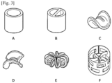
- the plastic elements can be balls, rings, or even tubes of different shapes, and dimensions varying from typically 25 to 50 mm. Different types of bulk packing may be suitable, some examples of which are shown in [ Fig.3 ].
- the first filter 7 and the second filter 9 are preferably placed so as to provide a circulation space 8 between the two.
- the percolat 5 leaving the first filter 7 can freely extend into the circulation space 8, and thus not accumulate in front of only part of the second filter 9.
- This arrangement makes it possible to optimize the use of the entire capacity of the second filter 9, and thus makes it possible to accelerate the filtration of the percolat 5 by the second filter 9.
- the flow space can for example extend to the ground over a distance greater than 10 cm.
- the second filter 9 can be arranged so as to provide a second circulation space 10 between said second filter 9 and the evacuation means 6.
- the evacuation means 6 may consist of one or more openings arranged in the edge between the rear wall and the ground, of the section of a pipe, for example with a diameter of 10 cm.
- the second filter 9 can be arranged over the entire width of the methanization unit, in this same edge, from one side wall 13a to the other 13b.
- a second circulation space 10 is provided between the second filter 9 and the evacuation means 6, for example by a channel, of height for example 5 to 10 cm, of width slightly less than the width of the second filter 9, just to maintain a support at ground level for said second filter, or even of the same width as the second filter 9, and the latter is partially inserted into the channel, leaving a space with the bottom of the channel.
- a second circulation space 10 all along the edge, and the percolat can pass through the second filter 9 vertically, exit the second filter by flowing downwards, then circulate freely towards one of the openings of the means of evacuation 6.
- the channel 17 can consist of a pipe open at the front and at the rear, through which the percolat 5 can circulate. You can place a filter at the entrance before pipe, to avoid blocking the entrance to the pipe by the biomass 2.
- two channels 17 can be arranged, one along each side wall 13a and 13b.
- the longitudinal channel 17 can also consist of a perforated pipe, the perforations allowing the percolat 5 to enter the pipe over the entire length of the loading space 1, without the biomass entering there.
- the risk of blocking the perforations can be reduced by placing a filter between the biomass 2 and the channel 17 over its entire length.
- the perforated pipe 17 can also be opened at the front to recover the excess percolate 5 having flowed towards the front.
- a wall 18 to protect the front wall, the function of which is to prevent the biomass from coming to rest on the front wall 11.
- the wall can be permeable to the percolate or we can have holes there. , to allow the percolat 5 to pass, which can then flow through the longitudinal channel(s) 17.
- the wall 18 also makes it possible to prevent the biomass 2 and the percolat from resting on the front wall of the processing unit. methanization and generate too much pressure.
- This allows the percolat 5 to circulate freely between the outlet of the second filter 9 and the evacuation means 6, and thus allows the percolat 5 to pass through said second filter 9 along a shortest crossing path, by not forcing the percolat 5 to travel a longitudinal or transverse path inside the second filter 9 .
Description
La présente invention se situe dans le domaine de la production de gaz à partir de matières organiques. Elle concerne plus particulièrement une unité de méthanisation.The present invention lies in the field of gas production from organic materials. It concerns more particularly a methanization unit.
La méthanisation est le processus naturel biologique de dégradation de la matière organique en absence d'oxygène. Cette dégradation produit un biogaz, utilisable comme source d'énergie.Anaerobic digestion is the natural biological process of degradation of organic matter in the absence of oxygen. This degradation produces biogas, which can be used as an energy source.
La méthanisation par voie sèche discontinue est une méthode dans laquelle on charge une chambre de méthanisation en biomasse. La méthanisation a ensuite lieu. Lorsque la méthanisation est terminée, on décharge la chambre des résidus de biomasse non transformés en biogaz, avant de recommencer. L'usage de plusieurs chambres en parallèle permet une production continue de biogaz.Batch dry methanization is a method in which a methanization chamber is loaded with biomass. Methanization then takes place. When the methanization is completed, the chamber is unloaded from the biomass residues not transformed into biogas, before starting again. The use of several chambers in parallel allows continuous production of biogas.
Afin d'accélérer la méthanisation, il est courant de procéder à une percolation de la biomasse, par exemple en distribuant du lisier sur son dessus. Cet apport de matières chargées en bactéries favorise la dégradation de la biomasse. De plus, étant liquide, le lisier se répand facilement dans toute la biomasse par capillarité et ruissellement.In order to accelerate methanization, it is common to percolate the biomass, for example by distributing slurry on top. This supply of materials loaded with bacteria promotes the degradation of biomass. In addition, being liquid, the slurry spreads easily throughout the biomass by capillary action and runoff.
Lorsqu'une partie du liquide de percolation a complètement traversé la biomasse, un liquide appelé percolat s'accumule dans le bas de la chambre de méthanisation. Ce liquide est composé de la partie du liquide de percolation qui n'est pas restée dans la biomasse, et de certaines particules fines de la biomasse emmenées par ce liquide. L'accumulation de percolat a souvent lieu à l'avant à ou à l'arrière de la biomasse. Il est alors souhaitable de sortir le percolat de la chambre de méthanisation, pour ne pas augmenter la pression sur les parois de la chambre. De plus la sortie du percolat hors de la chambre permet de récupérer un liquide chargé en bactéries qu'on peut réutiliser pour la percolation.When part of the percolation liquid has completely passed through the biomass, a liquid called percolate accumulates at the bottom of the methanization chamber. This liquid is composed of the part of the percolation liquid which has not remained in the biomass, and certain fine particles of the biomass carried away by this liquid. Percolate accumulation often takes place in front of or behind the biomass. It is then desirable to remove the percolat from the methanization chamber, so as not to increase the pressure on the walls of the chamber. In addition, the exit of the percolat from the chamber makes it possible to recover a liquid loaded with bacteria which can be reused for percolation.
Le document
Un objet de la présente invention est de proposer une unité de méthanisation par voie sèche discontinue permettant une méthanisation plus rapide de la biomasse.An object of the present invention is to propose a batch dry methanization unit allowing more rapid methanization of biomass.
La présente invention a pour objet de répondre au moins en partie aux objets précités en proposant une unité de méthanisation plus efficace, avec un écoulement plus fiable du percolat. A cet effet, elle propose une unité de méthanisation par voie sèche discontinue comportant un espace de chargement destiné à accueillir une biomasse à méthaniser, l'unité de méthanisation comprenant un moyen de percolation, et un moyen d'évacuation d'un percolat, dans laquelle :The present invention aims to respond at least in part to the aforementioned objects by proposing a more efficient methanization unit, with a more reliable flow of the percolat. For this purpose, it offers a discontinuous dry methanization unit comprising a loading space intended to accommodate biomass to be methanized, the methanization unit comprising a percolation means, and a means for evacuating a percolate, in which:
- l'unité de méthanisation comporte au moins un premier filtre disposé de sorte à séparer l'espace de chargement d'un espace de circulation,
- l'espace de circulation étant situé entre le premier filtre et le moyen d'évacuation,
- un deuxième filtre étant disposé entre l'espace de circulation et le moyen d'évacuation, ledit deuxième filtre étant configuré plus fin que le premier, de sorte à ne pas laisser passer certains éléments que le premier filtre laisse passer.
- the circulation space being located between the first filter and the evacuation means,
- a second filter being arranged between the circulation space and the evacuation means, said second filter being configured finer than the first, so as not to let certain elements pass that the first filter lets pass.
Grâce à ces dispositions, le percolat est bien réparti sur la surface du deuxième filtre, dont l'utilisation est ainsi optimisé.Thanks to these arrangements, the percolat is well distributed over the surface of the second filter, the use of which is thus optimized.
Selon d'autres caractéristiques :
- ledit deuxième filtre peut être disposé de sorte à ménager un deuxième espace de circulation entre ledit deuxième filtre et ledit moyen d'évacuation, permettant ainsi au percolat de traverser ledit deuxième filtre et d'en ressortir librement vers le deuxième espace de circulation, de sorte que l'utilisation dudit deuxième filtre est encore améliré,
- le premier filtre peut ne laisser passer que le liquide et les éléments dont au moins une dimension est inférieure à une dimension grossière, ladite dimension grossière étant comprise entre 10 et 80 mm, ce qui correspond à des dispositions efficaces pour l'invention,
- le deuxième filtre peut ne laisser passer que le liquide et les éléments dont au moins deux dimensions sont inférieures à une dimension fine, la dimension fine étant comprise entre 1 et 10 mm, ce qui correspond à des dispositions efficaces pour l'invention,
- le deuxième filtre peut comporter une cage grillagée dans laquelle sont placés des éléments filtrants tels que des cailloux ou des billes de plastique, ce qui est un mode efficace de réalisation dudit deuxième filtre,
- ladite unité de méthanisation peut comprendre un sol, une paroi avant, une paroi arrière, et deux parois latérales, le moyen d'évacuation étant disposé au niveau de l'intersection entre le sol et la paroi arrière, et le premier filtre s'étendant selon un plan incliné entre le sol et la paroi arrière, d'une paroi latérale à l'autre, ce qui permet un mode de réalisation simple et efficace de l'invention,
- le premier filtre peut comporter des éléments allongés, par exemple en bois, disposés parallèlement entre eux, s'appuyant d'un côté sur le sol et de l'autre côté sur la paroi arrière de l'unité de méthanisation, ce qui représente un mode de réalisation simple et efficace pour retenir la biomasse, et laisser passer le percolat,
- ladite unité de méthanisation peut comporter au moins un moyen d'écoulement couvert disposé au sol le long d'une paroi latérale de l'unité de méthanisation, permettant de faire couler du percolat de la paroi avant vers la paroi arrière sans traverser la biomasse, permettant d'éviter une accumulation de percolat à l'avant de l'unité de méthanisation, qui risquerait d'exercer une pression inacceptable sur la paroi avant.
- said second filter can be arranged so as to provide a second circulation space between said second filter and said evacuation means, thus allowing the percolat to pass through said second filter and to emerge freely towards the second circulation space, so that the use of said second filter is further improved,
- the first filter can only pass the liquid and the elements of which at least one dimension is less than a coarse dimension, said coarse dimension being between 10 and 80 mm, which corresponds to effective arrangements for the invention,
- the second filter can only pass the liquid and the elements of which at least two dimensions are less than a fine dimension, the fine dimension being between 1 and 10 mm, which corresponds to effective arrangements for the invention,
- the second filter may include a mesh cage in which filter elements such as pebbles or plastic balls are placed, which is an effective embodiment of said second filter,
- said methanization unit may comprise a floor, a front wall, a rear wall, and two side walls, the evacuation means being arranged at the level of the intersection between the floor and the rear wall, and the first filter extending according to an inclined plane between the ground and the rear wall, from one side wall to the other, which allows a simple and effective embodiment of the invention,
- the first filter may comprise elongated elements, for example made of wood, arranged parallel to each other, resting on one side on the ground and on the other side on the rear wall of the methanization unit, which represents a fashion simple and effective to retain the biomass and allow the percolate to pass through,
- said methanization unit may comprise at least one covered flow means arranged on the ground along a side wall of the methanization unit, making it possible to flow percolate from the front wall to the rear wall without passing through the biomass, making it possible to avoid an accumulation of percolate at the front of the methanization unit, which could exert unacceptable pressure on the front wall.
La présente invention concerne encore un Procédé de percolation d'une unité de méthanisation par voie sèche discontinue comportant successivement les étapes suivantes :
- versement d'un liquide de percolation sur une biomasse, ledit liquide de percolation devenant un percolat en traversant la biomasse,
- filtration du percolat par un premier filtre,
- filtration du percolat par un deuxième filtre plus fin que le premier filtre,
- évacuation du percolat hors de l'unité de méthanisation.
- pouring a percolation liquid onto a biomass, said percolation liquid becoming a percolate by passing through the biomass,
- filtration of the percolat by a first filter,
- filtration of the percolat by a second filter finer than the first filter,
- evacuation of the percolate from the methanization unit.
Grâce à ces dispositions, le deuxième filtre est protégé par le premier filtre, et le percolat s'écoule mieux à travers le deuxième filtre.Thanks to these arrangements, the second filter is protected by the first filter, and the percolate flows better through the second filter.
Selon un mode préféré de réalisation de l'invention, on ajoute en outre une étape de circulation du percolat dans un espace de circulation entre les étapes de filtration du percolat par le premier filtre et par le deuxième filtre ; une telle caractéristique permet d'optimiser le flux du percolat, qui se présente en entrée du deuxième filtre sur toute sa surface, et garantit ainsi une meilleure utilisation dudit deuxième filtre ; de préférence on ajoute encore une étape de circulation du percolat dans un deuxième espace de circulation entre les étapes de filtration du percolat par le deuxième filtre et l'étape d'évacuation du percolat, permettant d'optimiser également le flux de percolat à la sortie du deuxième filtre, et évitant d'obliger le percolat à circuler transversalement dans le deuxième filtre pour arriver jusqu'au moyen d'évacuation.According to a preferred embodiment of the invention, a stage of circulation of the percolat is also added in a circulation space between the stages of filtration of the percolat by the first filter and by the second filter; such a characteristic makes it possible to optimize the flow of the percolat, which is present at the inlet of the second filter over its entire surface, and thus guarantees better use of said second filter; preferably, a stage of circulation of the percolat is added in a second circulation space between the stages of filtration of the percolat by the second filter and the stage of evacuation of the percolat, also making it possible to optimize the flow of percolat at the outlet of the second filter, and avoiding forcing the percolat to circulate transversely in the second filter to reach the evacuation means.
La présente invention sera mieux comprise à la lecture de la description détaillée qui fait suite, en référence aux figures annexées dans lesquelles :
- [
Fig.1 ] La [Fig.1 ] est une vue en coupe longitudinale d'une unité de méthanisation selon un mode de réalisation préféré de l'invention, - [
Fig.2 ] La [Fig.2 ] est une vue schématique de l'arrière de l'unité de la [Fig.l], - [
Fig.3 ] La [Fig.3 ] est une vue schématique de différents modes de réalisation d'éléments filtrants.
- [
Fig.1 ] There [Fig.1 ] is a longitudinal sectional view of a methanization unit according to a preferred embodiment of the invention, - [
Fig.2 ] There [Fig.2 ] is a schematic view of the rear of the unit in [Fig.l], - [
Fig.3 ] There [Fig.3 ] is a schematic view of different embodiments of filter elements.
L'unité de méthanisation selon l'invention a été conçue pour la méthanisation par voie sèche discontinue.The methanization unit according to the invention was designed for batch dry methanization.
L'unité de méthanisation comporte un espace de chargement 1 destiné à accueillir une biomasse 2. La biomasse 2 peut comprendre des déchets verts telle que des plantes vertes, des branches, du fumier, du lisier, ou encore toute biomasse habituellement utilisée pour produire du biogaz.The methanization unit has a
L'unité de méthanisation comporte un moyen de percolation 3, permettant de répandre un liquide de percolation 4, par exemple du lisier, sur le dessus de la biomasse 2. Ce liquide de percolation 4 traverse la biomasse, et peut se charger de diverses particules à cette occasion. On appellera percolat 5, le liquide chargé obtenu.The methanization unit comprises a percolation means 3, making it possible to spread a
L'unité de méthanisation comporte également un moyen d'évacuation 6 du percolat 5.The methanization unit also includes a
Selon l'invention, l'unité de méthanisation comporte un premier filtre 7, disposé de sorte à séparer l'espace de chargement 1 d'un espace de circulation 8, l'espace de circulation 8 étant situé entre le premier filtre 7 et le moyen d'évacuation 6. On permet ainsi au percolat 5 de circuler librement une fois qu'il est sorti de la biomasse 2, et jusqu'au moyen d'évacuation 6. On évite aussi de boucher le moyen d'évacuation 6 par de la biomasse. On permet aussi au percolat 5 sortant de la biomasse 2 de s'étaler dans l'espace de circulation 8, et de ne pas s'accumuler dans un endroit éloigné du moyen d'évacuation 6. Une telle accumulation ralentirait l'évacuation et augmenterait le risque d'une pression importante sur une des parois de l'unité de méthanisation.According to the invention, the methanization unit comprises a
Par exemple, le moyen d'évacuation 6 peut consister en une ouverture de la section d'un tuyau, disposé dans un coin de l'unité de méthanisation. Le premier filtre 7 peut présenter la forme d'une calotte sphérique, disposé autour de ce coin. On crée ainsi une distance entre la biomasse 2 et le moyen d'évacuation 6, qui permet au percolat 5 de circuler librement.For example, the evacuation means 6 may consist of an opening in the section of a pipe, placed in a corner of the methanization unit. The
L'unité de méthanisation comporte un deuxième filtre 9, disposé entre l'espace de circulation et le moyen d'évacuation 6. Ce deuxième filtre 9 peut être disposé directement sur le moyen d'évacuation 6. Mais il peut aussi être disposé de sorte à ménager un deuxième espace de circulation 10, permettant au percolat 5 de circuler librement entre la sortie du deuxième filtre 9 et le moyen d'évacuation 6. Une telle configuration permet de disposer un deuxième filtre 9 d'une section bien plus grande que la section du moyen d'évacuation 6, et ainsi améliorer la vitesse de filtration, et/ou d'augmenter la durée d'utilisation du deuxième filtre 9 entre deux nettoyages.The methanization unit comprises a
Selon un mode préféré de réalisation de l'invention représenté aux [
Dans la suite de la description, le terme « avant » désigne la direction vers la paroi avant 11 de l'unité de méthanisation. De même, le terme « arrière » désigne la direction vers la paroi arrière 4 de l'unité de méthanisation.In the remainder of the description, the term “front” designates the direction towards the
Le sol 14 comporte de préférence une pente 16 descendant en direction de la paroi arrière 12. La pente 16 peut s'étendre sur l'intégralité du sol 14, ou sur une partie seulement du sol 14. La pente 16 permet de diriger le percolat 5 vers un moyen d'évacuation 6 du percolat hors de l'unité de méthanisation.The
Le premier filtre 7 est disposé de telle sorte qu'il se trouve entre la biomasse 2, disposée dans l'espace de chargement 1, et l'espace de circulation 8. Selon un mode préféré de réalisation de l'invention, le premier filtre 7 peut par exemple s'étendre sur le sol 14 d'une paroi latérale 13a à l'autre 13b.The
Le deuxième filtre 9 est disposé de telle sorte qu'il se trouve entre l'espace de circulation 8 et le moyen d'évacuation 6. Le deuxième filtre 9 peut par exemple s'étendre sur le sol 14, parallèlement et à l'arrière du premier filtre 7.The
Il est entendu que pour le premier filtre 7 aussi bien que pour le deuxième filtre 9, le terme « sur le sol » ne se limite pas à un filtre intégralement disposé sur le sol, et qu'un filtre dont une partie serait disposée sous le plan formé par le sol 14, est couvert par cette expression, tant que le filtre est apte à filtrer le percolat 5 s'écoulant sur le sol. De plus le sol 14 peut être entièrement planaire, mais il peut aussi comporter des renfoncements tels que des rainures. Un filtre 7, 9 placé dans une rainure du sol est considéré dans la présente invention comme un filtre placé sur le sol.It is understood that for the
Le deuxième filtre 9 est plus fin que le premier filtre 7, c'est-à-dire que le deuxième filtre 9 est tel qu'il ne laisse pas passer certains éléments que le premier filtre 7 laisse passer.The
Le premier filtre 7 est par exemple configuré pour ne laisser passer que le liquide et les éléments dont au moins une dimension est inférieure à une dimension grossière, ladite dimension grossière étant comprise entre 10 et 80 mm, selon les produits constituant la biomasse 2. Dans un premier mode de réalisation du premier filtre 7, celui-ci comprend une pluralité d'éléments allongés, par exemple en plastique, en bois ou en métal, disposés parallèlement entre eux, s'appuyant d'un côté sur le sol 14 et de l'autre côté sur la paroi arrière 12 de l'espace de chargement 1. Les éléments allongés peuvent ainsi être disposés avec un angle compris entre 30 et 60°, typiquement un angle de 45° par rapport à l'horizontale. Un autre mode de réalisation possible est une grille métallique, par exemple verticale.The
Le deuxième filtre 9 est par exemple configuré pour ne laisser passer que le liquide et les éléments dont au moins deux dimensions sont inférieures à une dimension fine, la dimension fine étant comprise entre 1 et 10 mm. Dans un premier mode de réalisation du deuxième filtre 9, celui-ci peut être réalisé par une enveloppe grillagée, par exemple faite d'une tôle percée de trous de 5 à 10 mm de diamètre, dans laquelle sont placés des éléments filtrants tels que des cailloux ou des éléments en plastique. Les éléments en plastique peuvent être des billes, des anneaux, ou encore des tubes de différentes formes, et de dimension variant de typiquement de 25 à 50 mm. Différents types de garnissage en vrac peuvent convenir, dont quelques exemples sont représentés en [
Le premier filtre 7 et le deuxième filtre 9 sont placés de préférence de sorte à ménager un espace de circulation 8 entre les deux. Ainsi, le percolat 5 en sortie du premier filtre 7 peut librement s'étendre dans l'espace de circulation 8, et ainsi ne pas s'accumuler devant une partie seulement du deuxième filtre 9. Cette disposition permet d'optimiser l'utilisation de toute la capacité du deuxième filtre 9, et permet ainsi d'accélérer la filtration du percolat 5 par le deuxième filtre 9. L'espace d'écoulement peut par exemple s'étendre au sol sur une distance supérieure à 10 cm.The
Le deuxième filtre 9 peut être disposé de sorte à ménager un deuxième espace de circulation 10 entre ledit deuxième filtre 9 et le moyen d'évacuation 6.The
Par exemple le moyen d'évacuation 6 peut consister en une ou plusieurs ouvertures disposées dans l'arête entre la paroi arrière et le sol, de la section d'un tuyau, par exemple de diamètre 10 cm. Le deuxième filtre 9 peut être disposé sur toute la largeur de l'unité de méthanisation, dans cette même arête, d'une paroi latérale 13a à l'autre 13b.For example, the evacuation means 6 may consist of one or more openings arranged in the edge between the rear wall and the ground, of the section of a pipe, for example with a diameter of 10 cm. The
Selon l'invention on ménage un deuxième espace de circulation 10 entre le deuxième filtre 9 et le moyen d'évacuation 6, par exemple par une rigole, de hauteur par exemple 5 à 10 cm, de largeur légèrement inférieure à la largeur du deuxième filtre 9, juste pour maintenir un support au niveau du sol pour ledit deuxième filtre, ou encore de même largeur que le deuxième filtre 9, et ce dernier s'insère partiellement dans la rigole, en laissant un espace avec le fond de la rigole. De cette façon on obtient un deuxième espace de circulation 10, tout le long de l'arête, et le percolat peut traverser le deuxième filtre 9 verticalement, sortir du deuxième filtre en coulant vers le bas, puis circuler librement vers l'une des ouvertures du moyen d'évacuation 6.According to the invention, a
Selon un mode préféré de réalisation de l'invention, on dispose au moins une rigole longitudinale 17, reliant l'avant à l'arrière, sur sensiblement toute la longueur de l'unité de méthanisation. Cela permet à du percolat 5 écoulé vers l'avant de l'unité de méthanisation d'emprunter ladite rigole longitudinale 17 pour circuler jusqu'à l'arrière, et rejoindre le moyen d'évacuation 6. On évite ainsi une accumulation de percolat 5 à l'avant de l'unité de méthanisation, et une pression trop importante sur sa paroi avant 11. La rigole 17 peut consister en une conduite ouverte à l'avant et à l'arrière, par laquelle le percolat 5 peut circuler. On peut placer un filtre à l'entrée avant de la conduite, pour éviter un bouchage de l'entrée de la conduite par la biomasse 2. On peut par exemple disposer deux rigoles 17, une le long de chaque paroi latérale 13a et 13b.According to a preferred embodiment of the invention, there is at least one
La rigole longitudinale 17 peut aussi consister en une conduite perforée, les perforations permettant au percolat 5 d'entrer dans la conduite sur toute la longueur de l'espace de chargement 1, sans que la biomasse y entre. On peut réduire le risque de bouchage des perforations en plaçant un filtre entre la biomasse 2 et la rigole 17 sur toute sa longueur. La conduite perforée 17 peut également être ouverte à l'avant pour récupérer le surplus de percolat 5 s'étant écoulé vers l'avant.The
En complément, on peut ajouter un mur 18 de protection de la paroi avant, dont la fonction est d'empêcher la biomasse de venir s'appuyer sur la paroi avant 11. Le mur peut être perméable au percolat ou on peut y disposer des trous, pour laisser passer le percolat 5, qui peut ensuite s'écouler par la ou les rigoles longitudinales 17. Le mur 18 permet aussi d'éviter que la biomasse 2 et le percolat ne s'appuient sur la paroi avant de l'unité de méthanisation et n'y génèrent une trop forte pression.In addition, we can add a
On procède à la percolation d'une unité de méthanisation par voie sèche discontinue en mettant successivement en oeuvre les étapes suivantes :
- versement d'un liquide de percolation sur une biomasse, ledit liquide de percolation
devenant un percolat 5 en traversant la biomasse 2, - filtration du percolat 5 par un
premier filtre 7, - filtration du percolat 5 par
un deuxième filtre 9 plus fin que lepremier filtre 7, - évacuation du percolat 5 hors de l'unité de méthanisation par
un moyen d'évacuation 6.
- pouring a percolation liquid onto a biomass, said percolation liquid becoming a
percolate 5 by passing through thebiomass 2, - filtration of the
percolat 5 by afirst filter 7, - filtration of the
percolat 5 by asecond filter 9 finer than thefirst filter 7, - evacuation of the
percolat 5 from the methanization unit by an evacuation means 6.
Selon un mode préféré de réalisation de l'invention, on dispose un espace de circulation 10 entre ledit premier filtre 7 et ledit moyen d'évacuation 6. Ceci permet au 5 de circuler librement vers toute la surface d'entrée du deuxième filtre 9, et améliore ainsi l'efficacité dudit deuxième filtre 9.According to a preferred embodiment of the invention, there is a
Selon un autre mode préféré de réalisation de l'invention, on dispose un deuxième espace de circulation 10 entre ledit deuxième filtre 9 et ledit moyen d'évacuation 6. Ceci permet au percolat 5 de circuler librement entre la sortie du deuxième filtre 9 et le moyen d'évacuation 6, et permet ainsi au percolat 5 de traverser ledit deuxième filtre 9 selon un parcours de traversée le plus court, en n'obligeant pas le percolat 5 à parcourir un trajet longitudinal ou transversal à l'intérieur du deuxième filtre 9.According to another preferred embodiment of the invention, there is a
Claims (8)
- Batch dry methanisation unit comprising a loading space (1) intended to receive a biomass (2) to be methanised, the methanisation unit comprising a percolation means (3), and a discharge means (6) for discharging a leachate (5), characterised in that- the methanisation unit comprises at least a first filter (7) arranged to separate the loading space (1) from a circulation space (8),- the circulation space (8) being located between the first filter (7) and the discharge means (6),- a second filter (9) being arranged between the circulation space (8) and the discharge means (6), said second filter (9) being configured finer than the first filter (7), so as not to let through certain elements that the first filter (7) lets through- said second filter (9) being arranged so as to provide a second circulation space (10) between said second filter (9) and said discharge means (6).
- Methanisation unit according to one of the previous claims wherein the first filter (7) only allows the passage of liquid and elements of which at least one dimension is smaller than a coarse dimension, said coarse dimension being comprised between 10 and 80 mm.
- Methanisation unit according to one of the previous claims in which the second filter (9) only lets through the liquid and the elements of which at least two dimensions are smaller than a fine dimension, the fine dimension being between 1 and 10 mm.
- Methanisation unit according to one of the previous claims, in which the second filter (9) comprises a wire mesh cage in which filtering elements such as pebbles or plastic balls are placed.
- Methanisation unit according to one of the previous claims, comprising a floor (14), a front wall (11), a rear wall (12), and two side walls (13a, 13b), the discharge means (6) being disposed at the intersection between the floor (14) and the rear wall (12), and the first filter (7) extending in an inclined plane between the floor (14) and the rear wall (12), from one side wall (13a) to the other (13b).
- Methanisation unit according to the previous claim, wherein the first filter (7) comprises elongated elements, for example made of wood, arranged parallel to each other, resting on one side on the floor (14) and on the other side on the rear wall (12) of the methanisation unit.
- Methanisation unit according to one of claims 5 or 6, comprising at least one covered flow means (17) arranged on the floor (14) along a side wall (13a, 13b) of the methanisation unit, allowing leachate (5) to flow from the front wall (11) to the rear wall (12) without passing through the biomass (2).
- Method for percolating a dry batch methanisation unit comprising the following steps in succession:- pouring a percolation liquid (4) onto a biomass (2), said percolation liquid (4) becoming a leachate (5) as it passes through the biomass (2),- filtration of the leachate (5) by a first filter (7),- circulating of the leachate (5) in a circulation space (8),- filtration of the leachate (5) by a second filter (9) which is finer than the first filter (7),- circulating of the leachate (5) in a second circulation space (10),- discharge of the leachate (5) from the methanisation unit.
Applications Claiming Priority (2)
| Application Number | Priority Date | Filing Date | Title |
|---|---|---|---|
| FR1913591A FR3103824B1 (en) | 2019-12-02 | 2019-12-02 | improved biogas unit |
| PCT/EP2020/082660 WO2021110419A1 (en) | 2019-12-02 | 2020-11-19 | Improved methanization unit |
Publications (3)
| Publication Number | Publication Date |
|---|---|
| EP4069817A1 EP4069817A1 (en) | 2022-10-12 |
| EP4069817C0 EP4069817C0 (en) | 2024-01-03 |
| EP4069817B1 true EP4069817B1 (en) | 2024-01-03 |
Family
ID=69630513
Family Applications (1)
| Application Number | Title | Priority Date | Filing Date |
|---|---|---|---|
| EP20808115.8A Active EP4069817B1 (en) | 2019-12-02 | 2020-11-19 | Improved methanization unit |
Country Status (4)
| Country | Link |
|---|---|
| EP (1) | EP4069817B1 (en) |
| CN (1) | CN114746538A (en) |
| FR (1) | FR3103824B1 (en) |
| WO (1) | WO2021110419A1 (en) |
Family Cites Families (6)
| Publication number | Priority date | Publication date | Assignee | Title |
|---|---|---|---|---|
| IT1219082B (en) * | 1988-03-07 | 1990-04-24 | Manifattura San Valeriano Spa | PROCEDURE AND PLANT FOR DISPOSAL AND RECYCLING OF URBAN SOLID WASTE BY ANAEROBIC FERMENTATION |
| DE10257849A1 (en) * | 2002-12-11 | 2004-07-08 | Ludwig Schiedermeier | Device for the anaerobic fermentation of biomass |
| DE202006002757U1 (en) | 2006-02-21 | 2007-06-28 | Bekon Energy Technologies Gmbh & Co. Kg | Bioreactor for the methanation of biomass with high solids content |
| DE102009011868A1 (en) * | 2008-12-23 | 2010-07-01 | Bekon Energy Technologies Gmbh & Co. Kg | Biogas plant for the methanation of biomass with high solids content |
| FR2981086B1 (en) * | 2011-10-10 | 2014-03-14 | Methajade | METHOD AND DEVICE FOR THE HYGIENIZATION OF A DIGESTAT DERIVED FROM DISCONTINUOUS DRY PHASE METHANIZATION |
| FR3058730B1 (en) * | 2016-11-17 | 2020-09-11 | Yannco | BIOGAS PRODUCTION SYSTEM FROM SOLID BIOMASS TRANSFORMED IN AT LEAST ONE REMOVABLE ANAEROBIC DIGESTER AND CORRESPONDING BIOGAS PROCESS |
-
2019
- 2019-12-02 FR FR1913591A patent/FR3103824B1/en active Active
-
2020
- 2020-11-19 WO PCT/EP2020/082660 patent/WO2021110419A1/en active Search and Examination
- 2020-11-19 CN CN202080084065.2A patent/CN114746538A/en active Pending
- 2020-11-19 EP EP20808115.8A patent/EP4069817B1/en active Active
Also Published As
| Publication number | Publication date |
|---|---|
| EP4069817C0 (en) | 2024-01-03 |
| EP4069817A1 (en) | 2022-10-12 |
| CN114746538A (en) | 2022-07-12 |
| WO2021110419A1 (en) | 2021-06-10 |
| FR3103824B1 (en) | 2022-09-09 |
| FR3103824A1 (en) | 2021-06-04 |
Similar Documents
| Publication | Publication Date | Title |
|---|---|---|
| EP1527032B1 (en) | Modular installation for composting organic material | |
| EP4069817B1 (en) | Improved methanization unit | |
| CA2259674C (en) | Device for clarification of a turbid liquid by flotation | |
| FR2940138A1 (en) | STRIPING COLUMN AND METHOD FOR EXTRACTING A COMPONENT FROM A LIQUID MEDIUM | |
| EP3342282A1 (en) | Filtering device for aquaponic production system | |
| FR2907022A1 (en) | Effluent treatment unit, especially for treating rainwater from overflow tank, comprises tank formed by assembling annular modules and having decantation and filtration compartments | |
| CA2044520A1 (en) | Granular filter wash water disposal means for said filters cleaned simultancously by water and air | |
| FR2774924A1 (en) | SEPARATOR FOR THREE-PHASE MIXTURE TO BE USED UNDER SEA LEVEL | |
| FR2958523A1 (en) | Dry toilet, has directing unit directing flow of suitable air in superimposed stages to evaporate liquid waste contained in each stage, and chamber equipped with device to separate liquid waste from solid waste supplied from seat block | |
| FR3019171A1 (en) | DEVICE AND METHOD FOR SANITIZING WASTEWATER | |
| EP1491507A1 (en) | Process of and digester for anaerobic digestion of sludge | |
| EP2181748B1 (en) | Hydrodynamic separator for cleaning a fluid stream | |
| FR2745195A1 (en) | RETENTION FILTER, INSTALLATION AND PROCESS FOR TREATING EFFLUENTS | |
| FR3042490B1 (en) | POLISHED AQUEOUS FLUX PURIFICATION STATION ELEMENT AND METHOD THEREFOR | |
| FR2800106A1 (en) | Plastic septic tank has pre-filter positioned beneath manhole and horizontal ventilation duct above diffuser | |
| WO2012153006A1 (en) | Dry toilets and method for treating waste from such toilets | |
| EP2712497A1 (en) | Method for filtering an air stream in a grain dryer | |
| EP1484095B1 (en) | Settler for the treatment of waste effluents | |
| FR2929608A1 (en) | Device for sanitizing wastewater originating from houses or small and medium-sized communities, comprises first and second filters for treating wastewater comprising filtration medium and plants, a body for settling materials, and a wall | |
| FR2761574A1 (en) | Hydroponic forcing trough for growing chicory | |
| EP1493804B1 (en) | Device for the automatic separation of liquid and solid bulk material in a wagon | |
| FR3029226B1 (en) | REMOVABLE DEGREE BASKET FOR A WATER LIFTING STATION | |
| EP1595588B1 (en) | Combined compact filter device | |
| WO2014033389A1 (en) | Device for the mechanical extraction of starch and corresponding method | |
| EP2735665A1 (en) | Water disposal apparatus of a retention container |
Legal Events
| Date | Code | Title | Description |
|---|---|---|---|
| STAA | Information on the status of an ep patent application or granted ep patent |
Free format text: STATUS: UNKNOWN |
|
| STAA | Information on the status of an ep patent application or granted ep patent |
Free format text: STATUS: THE INTERNATIONAL PUBLICATION HAS BEEN MADE |
|
| PUAI | Public reference made under article 153(3) epc to a published international application that has entered the european phase |
Free format text: ORIGINAL CODE: 0009012 |
|
| STAA | Information on the status of an ep patent application or granted ep patent |
Free format text: STATUS: REQUEST FOR EXAMINATION WAS MADE |
|
| 17P | Request for examination filed |
Effective date: 20220525 |
|
| AK | Designated contracting states |
Kind code of ref document: A1 Designated state(s): AL AT BE BG CH CY CZ DE DK EE ES FI FR GB GR HR HU IE IS IT LI LT LU LV MC MK MT NL NO PL PT RO RS SE SI SK SM TR |
|
| DAV | Request for validation of the european patent (deleted) | ||
| DAX | Request for extension of the european patent (deleted) | ||
| GRAP | Despatch of communication of intention to grant a patent |
Free format text: ORIGINAL CODE: EPIDOSNIGR1 |
|
| STAA | Information on the status of an ep patent application or granted ep patent |
Free format text: STATUS: GRANT OF PATENT IS INTENDED |
|
| INTG | Intention to grant announced |
Effective date: 20230707 |
|
| GRAS | Grant fee paid |
Free format text: ORIGINAL CODE: EPIDOSNIGR3 |
|
| GRAA | (expected) grant |
Free format text: ORIGINAL CODE: 0009210 |
|
| STAA | Information on the status of an ep patent application or granted ep patent |
Free format text: STATUS: THE PATENT HAS BEEN GRANTED |
|
| AK | Designated contracting states |
Kind code of ref document: B1 Designated state(s): AL AT BE BG CH CY CZ DE DK EE ES FI FR GB GR HR HU IE IS IT LI LT LU LV MC MK MT NL NO PL PT RO RS SE SI SK SM TR |
|
| REG | Reference to a national code |
Ref country code: GB Ref legal event code: FG4D Free format text: NOT ENGLISH |
|
| REG | Reference to a national code |
Ref country code: CH Ref legal event code: EP |
|
| REG | Reference to a national code |
Ref country code: DE Ref legal event code: R096 Ref document number: 602020023936 Country of ref document: DE |
|
| REG | Reference to a national code |
Ref country code: IE Ref legal event code: FG4D Free format text: LANGUAGE OF EP DOCUMENT: FRENCH |
|
| U01 | Request for unitary effect filed |
Effective date: 20240123 |
|
| U07 | Unitary effect registered |
Designated state(s): AT BE BG DE DK EE FI FR IT LT LU LV MT NL PT SE SI Effective date: 20240131 |