EP1527032B1 - Modulare kompostanlage für organische materialien - Google Patents
Modulare kompostanlage für organische materialien Download PDFInfo
- Publication number
- EP1527032B1 EP1527032B1 EP20030747488 EP03747488A EP1527032B1 EP 1527032 B1 EP1527032 B1 EP 1527032B1 EP 20030747488 EP20030747488 EP 20030747488 EP 03747488 A EP03747488 A EP 03747488A EP 1527032 B1 EP1527032 B1 EP 1527032B1
- Authority
- EP
- European Patent Office
- Prior art keywords
- installation
- ventilation
- accordance
- perforated pipe
- pipe run
- Prior art date
- Legal status (The legal status is an assumption and is not a legal conclusion. Google has not performed a legal analysis and makes no representation as to the accuracy of the status listed.)
- Expired - Lifetime
Links
Images


Classifications
-
- C—CHEMISTRY; METALLURGY
- C05—FERTILISERS; MANUFACTURE THEREOF
- C05F—ORGANIC FERTILISERS NOT COVERED BY SUBCLASSES C05B, C05C, e.g. FERTILISERS FROM WASTE OR REFUSE
- C05F17/00—Preparation of fertilisers characterised by biological or biochemical treatment steps, e.g. composting or fermentation
- C05F17/90—Apparatus therefor
- C05F17/964—Constructional parts, e.g. floors, covers or doors
- C05F17/971—Constructional parts, e.g. floors, covers or doors for feeding or discharging materials to be treated; for feeding or discharging other material
- C05F17/979—Constructional parts, e.g. floors, covers or doors for feeding or discharging materials to be treated; for feeding or discharging other material the other material being gaseous
-
- C—CHEMISTRY; METALLURGY
- C05—FERTILISERS; MANUFACTURE THEREOF
- C05F—ORGANIC FERTILISERS NOT COVERED BY SUBCLASSES C05B, C05C, e.g. FERTILISERS FROM WASTE OR REFUSE
- C05F17/00—Preparation of fertilisers characterised by biological or biochemical treatment steps, e.g. composting or fermentation
- C05F17/90—Apparatus therefor
- C05F17/964—Constructional parts, e.g. floors, covers or doors
- C05F17/971—Constructional parts, e.g. floors, covers or doors for feeding or discharging materials to be treated; for feeding or discharging other material
- C05F17/986—Constructional parts, e.g. floors, covers or doors for feeding or discharging materials to be treated; for feeding or discharging other material the other material being liquid
-
- Y—GENERAL TAGGING OF NEW TECHNOLOGICAL DEVELOPMENTS; GENERAL TAGGING OF CROSS-SECTIONAL TECHNOLOGIES SPANNING OVER SEVERAL SECTIONS OF THE IPC; TECHNICAL SUBJECTS COVERED BY FORMER USPC CROSS-REFERENCE ART COLLECTIONS [XRACs] AND DIGESTS
- Y02—TECHNOLOGIES OR APPLICATIONS FOR MITIGATION OR ADAPTATION AGAINST CLIMATE CHANGE
- Y02P—CLIMATE CHANGE MITIGATION TECHNOLOGIES IN THE PRODUCTION OR PROCESSING OF GOODS
- Y02P20/00—Technologies relating to chemical industry
- Y02P20/141—Feedstock
- Y02P20/145—Feedstock the feedstock being materials of biological origin
-
- Y—GENERAL TAGGING OF NEW TECHNOLOGICAL DEVELOPMENTS; GENERAL TAGGING OF CROSS-SECTIONAL TECHNOLOGIES SPANNING OVER SEVERAL SECTIONS OF THE IPC; TECHNICAL SUBJECTS COVERED BY FORMER USPC CROSS-REFERENCE ART COLLECTIONS [XRACs] AND DIGESTS
- Y02—TECHNOLOGIES OR APPLICATIONS FOR MITIGATION OR ADAPTATION AGAINST CLIMATE CHANGE
- Y02W—CLIMATE CHANGE MITIGATION TECHNOLOGIES RELATED TO WASTEWATER TREATMENT OR WASTE MANAGEMENT
- Y02W30/00—Technologies for solid waste management
- Y02W30/40—Bio-organic fraction processing; Production of fertilisers from the organic fraction of waste or refuse
Definitions
- the invention generally relates to composting facilities of organic materials.
- the invention relates to a composting plant of organic materials, comprising a set of cells in which the organic materials are stored for fermentation and an aeration device blowing or sucking air through the organic materials stored in the cells, each cell comprising a bottom slab, partitions and possibly a roof, the ventilation device comprising at least one fan provided with a suction orifice and a discharge orifice, and a ventilation duct connecting the suction port or discharge port to one or more cells.
- the cells of the same row are separated by a channel in which passes a manifold to which all the suction pipes are connected. This manifold is itself connected to the suction port of the fan.
- the first disadvantage is that the nature of the organic materials entering the facility may change depending on the waste inputs and contracts and operating authorizations obtained, and require an evolution of the organization or the operating process of the facility. installation, evolution which is difficult to implement in the installations of the prior art.
- the second disadvantage is that the insertion of poles directly fixed in the slab prevents any evolution of the fermentation processes.
- the third drawback is that the ventilation device of the installations is not optimized for the existing fan and duct standards. This aspect is important because the efficiency of the composting process, and in particular the height of the materials to be composted and the nature of the materials and structuring materials to mix, is directly related to the efficiency of the aeration.
- the fourth disadvantage is that leachates are observed at the edges of heaps of organic materials, along the longitudinal walls of the cells. This presence of leachate is a source of bad smell and is unsightly.
- the fifth disadvantage is that the development of piloted ventilation technology has led to adopt solutions with buried ventilation ducts, consisting of a buried and pierced pipe to which are connected aerial plastic pipettes ensuring the diffusion or the suction of air through the waste.
- the air pipettes are made in one piece, and are directly inserted or clipped on the ventilation pipe.
- These pipettes have the disadvantage of obliging the equipment designers Aeraulic to be equipped with several injection molds depending on the height of the air pipettes desired or to perform an expensive bar turning pipettes to a particular dimension.
- the sixth disadvantage is that, for buried ventilation ducts and mainly for air suction in the fermentation process, the recovery of leachates flowing through the air pipettes into the buried duct requires the installation of siphons. aeraulics which ensure the recovery of these leachate and which increase the civil engineering. These siphons permanently store leachate, which is an additional source of malodorance on the sites.
- the present invention aims to overcome the drawbacks mentioned above, and to propose a new design of installation, allowing flexible operation depending on the materials to be treated, eliminating aeraulic siphons, and optimized point of cost. Moreover, this design change requires rethinking the ventilation device, which allows at the same time to eliminate some defects of the prior art.
- the installation of the invention which moreover conforms to the generic definition given in the preamble above, is essentially characterized in that it comprises a base plate constituting the floor slabs of different cells, radier comprising means for arranging the partitions of the cells at different predetermined positions, the size of the cells being thereby adjustable according to the needs.
- the invention relates to an installation according to claim 1.
- the means for separating the partitions from the cells in a removable manner comprise reservations made in the slab,
- each partition comprises a plurality of posts distributed along the partition and cladding elements removably attached to these posts, the space between two adjacent posts being closed by the cladding elements extending between said posts, the posts being detachably engaged by respective lower ends each in a reservation of the raft.
- each pierced section of the ventilation duct is embedded in the raft, the aeration device comprising a plurality of pipettes each opening through the aeration device comprising a lower end in an orifice carried by the pierced section and an upper end. on a free face of the slab, and devices for clipping the pipettes on the pierced section, each clipping device having the shape of a tubular segment comprising at a first end an outer peripheral groove in which is engaged a peripheral edge of the orifice in which the pipette opens, this pipette being force-fitted on a second end of the clipping device opposite to the first.
- two adjacent posts of the same partition may comprise respective longitudinal grooves facing each other, the cladding elements closing the space between the two adjacent posts having opposite edges engaged in the two grooves facing each other.
- the cell may comprise two parallel and opposite partitions each having an upper longitudinal edge, these opposing partitions comprising longitudinal posts extending along their respective upper longitudinal edges, these longitudinal posts comprising respective longitudinal grooves facing each other. , roof elements being engaged by opposite edges in the grooves facing the two longitudinal poles.
- each adjacent post of the same partition may comprise in the upper position additional longitudinal grooves perpendicular to the vertical grooves allowing through removable partitions to close the cells defined by the lateral horizontal partitions, and allow the formation of a roof to close the cell.
- the raft may comprise a gutter and have a portion sloped towards the gutter, the raft also comprising a plurality of leachate discharge orifices distributed along the gutter at the bottom of said sloping portion, these orifices of evacuation leading into this gutter.
- the reservations are arranged in several parallel rows perpendicular to the gutter, the ventilation duct comprising pierced sections extending in the median planes of said parallel rows and sloping toward respective first ends located in the gutter, these first ends of the ducts.
- ventilation systems are equipped with leachate discharge valves.
- the ventilation member comprises a low point provided with a condensate drain valve.
- the leachate and / or condensate drain valves may be membrane or sleeve valves controlled by a compressed air controller.
- control device leachate discharge valves and condensate can be manual or automated and then include a solenoid valve can adopt an open position in which the drain valves are supplied with compressed air and are in closed positions, and a position closed in which the drain valves are not supplied with compressed air and are in open positions, the solenoid valve adopting its open position when the ventilation member operates and its closed position when the ventilation member does not work.
- each pierced section of the ventilation duct is embedded in the raft.
- the raft may include a tubular reservation in which extends the pierced section of the ventilation duct, this tubular reservation allowing the passage of ventilation ducts opening into the gutter; this tubular reservation comprising at least one of gravity evacuation ports leachate directly into the tubular reservation and allowing the gravitational flow leachate in the gutter.
- the pierced portion of the ventilation duct may have a second end opposite to the first provided with a tube opening on the free face of the raft at one end, this end being plugged by a screwable or removable cap, and can be connected to a device for injecting rinsing water from the pierced section.
- the ventilation duct may have two opposite ends each provided with a screwable or removable cap and each without airflow siphon, including for aeration devices operating in suction.
- each pierced section of the ventilation duct may be disposed on the free face of the slab, its first end being connected to the suction orifice of the ventilation member, this pierced section being pierced with a plurality of holes. , the number of holes per unit length of the drilled section progressively increasing along the drilled section, and being minimum at the first end and maximum at a second end of said section opposite the first, or the holes being distributed on the periphery of sections ventilation duct, the gap between the sections being reduced the further one moves away from the ventilation member.
- the raft may comprise secondary gutters, each pierced section of the ventilation duct extending along a secondary gutter, its first end being connected to the suction port of the ventilation member, each pierced section. having a plurality of sections each pierced with holes distributed along the periphery of said section, the holes in a lower half of a section being in larger number and / or larger in diameter than the holes in an upper half of said section.
- the aeration device may comprise an air inlet coming from the outside of the installation, an air outlet towards the outside of the installation, and one or more ventilation flaps closing the inlet. air and / or the air outlet when the ventilation device is stopped and that the cells are covered by a roof.
- the air blown or sucked through the organic materials can pass into a biological filter after leaving the cell, the biological filter comprising a bottom slab constituted by the raft, and reservations, poles and partitions of the same type than those of the cells.
- the composting plant of organic material 1 comprises a set of cells 10 in which the organic materials 1 are stored for fermentation, and an aeration device 20 blowing or sucking air through the organic materials 1 stored in the cells 10.
- the organic materials to be treated fall into three categories: green waste, such as grass cut during lawn clippings, biowaste, such as fruits and vegetables, and sludge.
- the installation typically comprises four cells, but may comprise more or less depending on the composition of the incoming organic materials and the treatment method applied thereto.
- This process generally comprises a succession of fermentation phases, each followed by an operation of sorting and orienting the materials according to their state at the end of the fermentation phase.
- the invention does not relate to facilities for sorting and screening organic materials, which are therefore not described here.
- the fermentation phases are carried out in the different cells of the plant.
- Each cell 10 comprises a bottom slab 11, partitions 12 and possibly a roof 16.
- the aeration device 20 comprises at least one ventilation member 21, typically a fan, provided with a suction port of the air 211 and an outlet air 212, and a ventilation duct 22 connecting the suction port 211 or the discharge port 212 to one or more cells 10.
- the installation can therefore operate either in suction or in discharge.
- the installation comprises a raft 40 constituting the bottom slabs 11 of different cells 10, this slab 40 comprising means 41 for arranging the partitions 12 of the cells 10 at different predetermined positions, the size of the cells 10 being this fact is adaptable according to the needs.
- the means 41 for arranging the partitions 12 of the cells 10 comprise reservoirs 42 formed in the raft 40.
- reservations 42 are preferably arranged in several parallel rows extending in a longitudinal direction, the rows being evenly spaced from one another, and the reservations 42 of the same row being equally spaced regularly.
- the reservations 42 are thus arranged on the surface of the slab 40 to form the nodes of a grid of rectangular mesh.
- each partition 12 comprises a plurality of posts 13 distributed along the partition 12, and cladding elements 14 removably attached to these posts 13.
- the space between two adjacent posts 13 in a partition 12 is closed over the entire height of the partition by the cladding elements 14 extending between said posts 13.
- the posts 13 are detachably engaged by respective lower ends each in a reservation 42 of the slab 40.
- the cells 10 of the invention have a rectangular shape elongate in the longitudinal direction, and generally comprise four partitions 12 straight, two longitudinal partitions 121 parallel and opposite and two transverse walls 122 parallel and opposite. They can be equipped with a roof 16.
- the posts 13 of the same longitudinal partition 121 are engaged in the reservations 42 of the same row.
- the posts 13 of a transverse partition 122 are engaged in reservations 42 belonging to different rows.
- the posts 13 have different shapes depending on whether they are arranged at an angle between two partitions 12 or that they support a removable roof for closing a cell.
- the posts 13 all comprise one or more grooves 131, these grooves 131 having identical crenellated sections.
- Columns 13 said mid-wall, that is to say that are not arranged at an angle, are metal profiles having an I-shaped. They therefore comprise two grooves 131 parallel and opposite, and two full side faces opposed.
- the corner posts 13 each comprise a first I-shaped section identical to a partition center post, and a second section rigidly fixed to the I-section.
- This second profile has a crenel section, the same shape and the same size as half of the first profile I.
- This second section thus comprises a longitudinal groove 131 on one side, and a solid face on the other side opposite to the groove. It is plated by its solid face on one of the two solid side faces of the first I-profile, so that the corner post 13 has three identical grooves 131, open on three different sides, two opposite sides and one side perpendicular to the other two.
- the profiles are attached to each other by simple means, such as welding or bolts.
- two adjacent posts 13 of the same partition 12 have grooves 131 respectively parallel and facing. This is true that the two posts are two mid-wall studs or a mid-wall stud and a corner post.
- the cladding elements 14 closing the space between two adjacent posts 13 have opposite edges releasably engaged in the grooves 131 facing the two posts 13.
- These cladding elements 14 are for example wooden planks, wooden planks, plastic material plates, or canvas stretched on rigid frames.
- the sealing between the different elements of cladding and between the cladding elements and the ground is reinforced, for example by a joint placed in the form of paste.
- the reservations 42 are of cylindrical shape and are coated internally in steel. They have a diameter adapted so that the posts 13 of the wall medium are supported along four generatrices of the reservation 42, by the free edges of the four branches of the I.
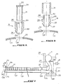
- Each post 13 is equipped with a flange 132 in the form of a disc, visible on the Figures 2A and 2B , which closes the reservation 42 in which said post is engaged.
- This flange is pierced by an aperture 133 in the shape of I, corresponding in size to the section of the end of the posts 13.
- the ends of the posts 13 pass through these openings 133 to engage in the reservations 42.
- the collars may be metal or plastic, and are fixed on the posts 13. They prevent organic materials or leachate from entering the reservation.
- the latter can be closed by plugs (not shown) removably fixed in the reservations by screwing or clipping.
- the longitudinal partitions 121 opposite the cell 10 shown on the figure 4 comprise longitudinal posts 15 extending along respective upper longitudinal edges 123 of these partitions.
- These longitudinal posts 15 are identical to the columns 13 of the middle of the partition and have an I-section, so that the longitudinal posts 15 of the two opposite longitudinal partitions comprise respective longitudinal grooves 151 facing.
- Roof elements 16 are engaged by opposite edges in the grooves 151 facing the longitudinal posts 15 of the two longitudinal partitions 121.
- roof elements 16 may be wooden planks, wooden planks, or a tarpaulin deployable and retractable manually or automatically.
- the posts 13 and the longitudinal posts 15 are pierced by eyes, used to lift and move these posts using lifting means.
- the installation can operate either in suction or in discharge.
- the ventilation air intake duct 22 is connected to the suction port 211 of the ventilator 21.
- the air coming from outside penetrates inside the cell 10 by the top of the waste or in the case where the cell is closed by a roof 16, by an air inlet 30, passes to through the organic materials 1, then is captured by the ventilation duct 24, sucked by the fan 21 and discharged to a biological filter 50, and leaves the biological filter 50 to be rejected to the outside by an air outlet 31.
- the cell 10 and the biological filter 50 are respectively maintained at a vacuum and at an overpressure relative to the outside when the fan 21 is operating.
- the figures 8 and 10 represent two embodiments of the composting installation corresponding to the first case.
- the ventilation duct 22 is connected to the discharge port 212 of the fan 21.
- the air coming from the outside is sucked by the fan 21, discharged into the ventilation duct 22 and then blown inside the cell 10 under the organic materials 1.
- the air passes therethrough and is then directed to the biological filter 50, and out of this biological filter 50 to be discharged to the outside by the air outlet 31.
- the cell 10 and the biological filter 50 are held in overpressure relative to the outside when the fan 21 is running.
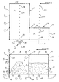
- the figure 1 represents a first embodiment of the composting installation corresponding to the second case.
- the slab 40 comprises a channel 44 and has a portion 45 sloped towards an edge of this channel 44, on which is disposed one or more cells 10.
- Two fermentation cells and a bio-filter are represented on the figure 1 .
- the longitudinal partitions 121 of these cells 10 extend perpendicularly to this channel 44.
- One of the two transverse partitions 122 of each cell 10 extends along the channel 44.
- the installation may comprise several rafts 40 carrying cells 10, associated with several gutters 44 if necessary.
- It may for example comprise two racks 40, arranged on two opposite sides of the channel 44 and both sloping towards the same gutter 44.
- the ventilation device 20 comprises at least one fan 21 per cell 10, this fan being fixed to the transverse wall 122 of the cell located along the channel 44. It is also possible to use the same fan for several cells 10 or the fan is not attached to the cell wall.
- the ventilation device 20 also comprises a plurality of pierced sections 23 of ventilation duct 22 embedded in the sloping portion 45 of the slab 40. These pierced sections 23 are parallel and perpendicular to the channel 44, and extend in the mid-planes of the slats. rows of reservations 42.
- the fans 21 are each connected to one or more of these pierced sections 23 by air sections 24 of ventilation duct.
- Each pierced portion 23 is pierced with holes 231, aligned, regularly arranged every twenty centimeters or so along the pierced section 23 and arranged at the top thereof.
- the aeration device 20 also comprises a plurality of vertical pipettes 25 each opening through a lower end into one of the openings 231 and by an upper end on a free face 43 of the slab 40, and clipping devices 26 of the pipettes 25 on the pierced section 23.
- the air discharged by the fan 21 in the pierced section 23 is blown into the cell 10 by these pipettes.
- the pipettes 25 are about twenty centimeters long.
- each clipping device 26 has the shape of a tubular segment, comprising at a first end 261 an outer peripheral groove 263 in which is engaged a peripheral edge 232 of the orifice 231 into which the pipette 25, this pipette 25 being force-fitted on a second end 262 of the clipping device 26 opposite to the first.
- the first end 261 of the clipping device 26 has a cut free edge, facilitating the introduction of the clipping device in the orifice 231.
- the pipette 25 can be fitted inside the second end 262 of the clipping device 26, as shown in FIG. Figure 6A , or outside this second end, as shown on the Figure 6B .
- the clipping device 26 has an interior light 264 shown on the Figure 6A , comprising a first tubular portion on the side of the first end 261 of a size corresponding to the inside diameter of the pipette 25, and a second tubular portion wider than the first at the second end 262 of the clipping device, this second portion forming a housing
- the second portion carries peripheral ribs 265 blocking the pipette 25 in position when the latter is engaged in the clipping device 26, and has an axial ring bottom 266 against which the pipette 25 abuts. .
- This ring bottom 266 is pierced at its center by one end of the first tubular portion.
- the clipping device 26 comprises a first axial portion 267 on the side of the first end 261, and a second axial portion 268 on the side of the second end 262 of outside diameter smaller than the first axial portion and separated therefrom by a shoulder 269.
- the outer diameter of the second axial portion 268 corresponds to the inner diameter of the pipette 25.
- the second axial portion 268 carries peripheral ribs 265.
- the pipette 25 is cut around the second axial portion 268 and abuts against the shoulder 269, the ribs 265 blocking the pipette 25 in position.
- Each pipette 25 carries at its end opening on the free face 43 of the raft 40 a plug 251, having in its center a hole 252.
- the plug is force-fitted at the end of the pipette.
- the surface of the orifice 231 must be greater than three times the area of the hole 252 of the stopper 251.
- the cross section of the pierced section 23 is greater in area than the sum of the surfaces of the holes 252 of all the pipettes 25 opening into said pierced section. It is thus possible to create a uniform pressure by blowing air (blowing) into the pierced section, transforming it into a pressure chamber, and to obtain identical air flow rates in all the pipettes.
- This method of attaching the pipettes to the pierced section is particularly advantageous because it is simple and fast, and does not require threading on the pipettes. Moreover, it is very easy for the supplier of the pipettes to adapt them in length according to the thickness of the raft.
- the pipettes are indeed straight plastic tubes, which can be cut to the right dimensions.
- the raft 40 includes tubular reservations 47 perpendicular to the channel 44 in which the ventilation ducts 23 pass, each tubular reservation 47 opening into the channel 44 and being sloped towards said gutter.
- the raft 40 also comprises a plurality of leachate discharge orifices 46 distributed along the gutter 44, at the bottom of the sloping portion 45 of the slab 44. More specifically, the slab comprises a gravitational discharge orifice 46 associated leachate at each embedded portion 23 and tubular reservation 47, this discharge orifice being located at the end of the line formed by the ends of the pipettes 25 opening on the free face 43 of the raft.
- each cell 10 there is in each cell 10 at least one discharge port 46, close to the transverse partition 122 carrying the fan 21, and located on the inner side of the cell.
- the orifice 46 may consist of a pipette 25 of the type described above, the pipette 25 being clipped to said tubular reservation 47 by means of the same clipping systems 26 used for the use of the air pipettes 25.
- Leachate resulting from the fermentation of the organic materials flows down the slope of the slab, and flows through the discharge orifice, first in the tubular reservation 47, then in the channel 44 with this pipette leachate 46.
- each pierced section 23 is sloped towards a first end 233, this first end being located in the channel 44 and being provided with a leachate discharge valve 234 and a screwable or removable cap 239.
- the leachates that flow through the pipettes 25 in the a Vogellic sections pierced accumulate at the first ends 233 and can be resumed and evacuated.
- each fan 21 comprises a low point provided with a condensate drain valve 213.
- leachate discharge valves and condensates 234 and 213 are diaphragm or sleeve valves, manual or controlled by a compressed air controller.
- the automatic device for controlling the diaphragm or sleeve valves comprises a solenoid valve 29 for each fan 21.
- This solenoid valve 29 controls the condensate drain valve 213 of the fan 21 and the leachate discharge valve (s) 234 of the associated drilled section (s). to the fan 21.
- the solenoid valve 29 can adopt an open position in which leachate discharge valves and condensates 234 and 213 are supplied with compressed air and are in closed positions, and a closed position in which the leachate discharge valves and condensates 234 and 213 are not supplied with compressed air and are in open positions.
- the solenoid valve 29 assumes its open position when the fan 21 is operating and its closed position when the fan 21 is not operating.
- Leachate discharge valves and condensates 234 and 213 may for example be connected to a liquid pumping device for discharging automatically leachate and condensate.
- This pumping device can be pneumatic.
- Each pierced section 23 has a second end 235 opposite the first end 233, provided with a tube 236 opening on the free face 43 of the slab by a threaded end 237.
- a plug 238 is releasably screwed onto this threaded end 237. This plug 238 can be removed and the tube 236 can be connected to a rinsing water injection device of the pierced section.
- the embedded portion 23 is plugged at its second end 235 by a sealed plug 235 '.
- the air blown through the organic materials 1 passes after leaving the cell 10 in the biological filter 50.
- This biological filter 50 is made in the same way as the cells 10, and comprises a bottom slab 51 constituted by the slab 40, reservations 42 and partitions 52 and optionally a roof 53 of the same types as those of the cells 10 with 16.
- the space thus defined is partially filled with a mixture of peat, compost, bark and other absorbent materials constituting the filter media.
- the cells 10 have a common partition with the biological filter 50, the air flowing from each cell to the filter through an opening made in a very simple manner, by removing a cladding element 14 from the common partition.
- the cells 10 and the filters 50 then have common partitions.
- outlets are created by removing a cladding element 14 from each common partition, the air passing from one filter to another through the space of the cladding that has been removed.
- the air inlet and outlet of the same filter are located one at the bottom of a partition and the other at the top of a partition, so as to force air to pass through the filter medium .
- an additional air deodorization stage such as a first sparge stage in a suitable solution and / or a second stage of molecular trapping of the smelly molecules, just before or after just after the biological filter or in one or more biological filters.
- the air inlets are the suction ports 211 of the fans 21, and the air outlets 31 are created by removing a bandage member 14 from a partition 52 of each biological filter.
- the raft 40 comprises a plurality of mutually parallel secondary channels 48 extending perpendicularly to the channel 44 and each opening therein through respective ends.
- These secondary gutters 48 extend in median planes of rows of reservations 42. Each cell 10 is thus crossed by at least one secondary gutter 48.
- the ventilation device 20 comprises for each cell 10 of the installation at least one pierced section 27 of ventilation duct extending along the secondary channel 48 passing through the cell 10, this pierced section having a first end 271 connected to the suction port 211 of a fan 21 and a second plugged end 273 opposite the first end.
- Each pierced section 27 has a plurality of pierced sections, each pierced with holes 272 distributed along the periphery of said section.
- the holes 272 located in a lower half of a pierced section are larger in number and / or have larger diameters than the holes 272 located in an upper half of said section, as shown in FIG. figure 9 .
- This feature improves the aeration of organic materials, the holes in the lower half being less likely to be plugged and clogged with organic materials than the holes in the upper half.
- the raft does not include secondary channels
- the ventilation device 20 comprises for each cell 10 a pierced section 28 of ventilation duct arranged directly on the free surface of the raft and extending substantially in the same position as the section pierced corresponding of the first variant.
- this pierced portion 28 has a first end 281 connected to the suction port 211 of a fan 21 and a second end blocked 284 opposite the first end.
- This pierced section 28 has a plurality of sections 282 pierced with holes 283, the number of holes 283 per unit length of the pierced section progressively increasing along the pierced section 28, and being minimum at the first end 281 and maximum at the second end. 284, or, for the same number of holes per section, the spacing of the sections being reduced as one approaches the second end 284.
- This characteristic makes it possible to have holes of the same diameter regardless of the length of the ventilation pipe and to have a suction air flow per unit of air. identical length throughout the section, independent of the distance from the entrance of the pierced section.
- the air inlets 30 are created by removing a cladding member 14 from a partition 12 of each cell 10, and the air outlets are created by removing a cladding member from a partition. 52 of each filter biologically 50.
- each biological filter 50 is done by a pierced pipe of the same type as those used for suction in the cells 10.
- the cells are then placed under the roofs and the air is drawn directly to the outside.
- the insertion of the sleeve or membrane valves manual or automated leachate recovery allows to remove at each end of the air ducts aeraulic siphons.
- the leachate discharge orifices 46 in the second embodiment, open directly into the channel 44. They are not represented on the figures 8 and 10 . Leachate passes under the cladding of partitions 122 or by reservations 48.
- the ventilation device 20 includes ventilation flaps 32 closing the door. or the air inlets 30 and the or the air outlets 31 when the fan or fans are stopped, preventing air from escaping when the cells are pressurized or depressed.
- valves 32 are simple pivoting flaps mounted on the partitions.
- valves 32 open and close under the effect of the pressure difference between the inside of the cells or filters and the outside.
- valves prevent odors from spreading around the installation while it is stopped.
- any platform equipped according to the principles of the invention can be provided in the form of a roof assembly consisting, in the first place, reservations 42 and cladding columns that can be directly supplied to various road networks companies, and that it is possible outside the slab, to avoid the expensive use of concrete.
- the invention also makes it possible, with the same equipment, to design both fermentation cells and biofilters and to be able to juxtapose these equipment side by side by systematically reducing the number of partitions.
Landscapes
- Chemical & Material Sciences (AREA)
- Chemical Kinetics & Catalysis (AREA)
- Life Sciences & Earth Sciences (AREA)
- Engineering & Computer Science (AREA)
- Biochemistry (AREA)
- Biotechnology (AREA)
- Health & Medical Sciences (AREA)
- General Chemical & Material Sciences (AREA)
- Microbiology (AREA)
- Molecular Biology (AREA)
- Organic Chemistry (AREA)
- Apparatus Associated With Microorganisms And Enzymes (AREA)
- Fertilizers (AREA)
- Processing Of Solid Wastes (AREA)
Claims (18)
- Kompostanlage für organische Stoffe (1), umfassend eine Anordnung von Zellen (10), in denen die organischen Stoffe (1) zur Gärung zwischengelagert sind, und eine Belüftungsvorrichtung (20), die Luft durch die organischen Stoffe (1), die in den Zellen (10) zwischengelagert sind, einbläst oder absaugt, wobei jede Zelle (10) eine Bodenplatte (11) und Trennwände (12) umfaßt, wobei jede Trennwand (12) mehreren Stützen (13) aufweist, die entlang der Trennwand (12) verteilt sind, und Wandverkleidungselemente (14), die abnehmbar an diesen Stützen (13) befestigt sind, wobei der Raum zwischen zwei benachbarten Stützen (13) durch die Wandverkleidungselemente (14) ausgefüllt ist, die sich zwischen den Stützen (13) erstrecken, wobei die Belüftungsvorrichtung (20) mindestens ein Belüftungsorgan (21), das mit einer Ansaugöffnung (211) und einer Austrittsöffnung (212) versehen ist, und ein Belüftungsrohr (22) umfasst, wobei das Belüftungsrohr gelochte Abschnitte (23) umfasst, die mehrere Pipetten (25) aufnehmen, die jeweils durch ein unteres Ende in eine Öffnung (231), die in dem gelochten Abschnitt (23) angeordnet ist, und durch ein oberes Ende auf eine freie Fläche (43) einer Sohle (40) münden, wobei das Belüftungsrohr die Ansaugöffnung (211) oder die Austrittsöffnung (212) mit einer oder mehreren Zellen (10) verbindet, dadurch gekennzeichnet, dass sie eine Sohle (40) aufweist, die die Bodenplatten (11) von verschiedenen Zellen (10) bildet, wobei diese Sohle (40) Mittel (41) umfasst, um die Trennwände (12) der Zellen (10) abnehmbar an verschiedenen vorgegebenen Positionen anzuordnen, wobei die Größe der Zellen (10) aus diesem Grund entsprechend den Bedürfnissen variierbar ist, wobei die Mittel (41), um die Trennwände (12) der Zellen (10) abnehmbar anzuordnen, Aussparungen (42) von Stützen aufweisen, die in der Sohle (40) angeordnet sind und wobei die Stützen (13) so angeordnet sind, dass sie jeweils abnehmbar durch ihre jeweiligen unteren Enden in einer der Aussparungen (42) der Stützen der Sohle (40) in Eingriff stehen,
und dass die Pipetten durch Klemmvorrichtungen (26) auf den gelochten Abschnitt (23) geklemmt sind und dass jede Klemmvorrichtung (26) die Form eines röhrenförmigen Segments aufweist, das an einem ersten Ende (261) eine äußere umlaufende Nut (262) aufweist, in welche eine umlaufende Kante (232) der öffnung (231) eingreift, in welche die Pipette (25) mündet, wobei diese Pipette (25) mit Kraft an einem zweiten Ende (262) der Klemmvorrichtung (26), die sich gegenüber der ersten befindet, eingesetzt wird. - Anlage nach Anspruch 1, dadurch gekennzeichnet, dass die Zelle (10) zwei parallele und gegenüberliegende Trennwände (12) aufweist, die jeweils eine obere Längskante (123) aufweisen, wobei diese gegenüberliegenden Trennwände (12) Längsstützen (15) umfassen, die sich entlang ihrer jeweiligen oberen Längskanten (123) erstrecken, wobei diese Längsstützen (15) jeweils gegenüberliegende Längsnuten (151) umfassen, wobei Dachelemente (16) durch gegenüberliegende Kanten mit den Nuten (151) gegenüber der Längsstützen (15) in Eingriff stehen.
- Anlage nach Anspruch 1 oder 2, dadurch gekennzeichnet, dass zwei benachbarte Stützen (13) ein- und derselben Trennwand (12) jeweils gegenüberliegende Längsnuten (131) umfassen, wobei die Wandverkleidungselemente (14), die den Raum zwischen den beiden benachbarten Stützen (13) ausfüllen, gegenüberliegende Kanten aufweisen, die mit den beiden gegenüberliegenden Nuten (131) in Eingriff stehen.
- Anlage nach einem der Ansprüche 1 bis 3, dadurch gekennzeichnet, dass die Sohle (40) eine Rinne (44) umfasst und einen in Richtung dieser Rinne (44) geneigten Teil (45) aufweist.
- Anlage nach Anspruch 4, dadurch gekennzeichnet, dass die Aussparungen (42) der Stützen in mehreren parallelen Reihen angeordnet sind, die senkrecht zu der Rinne (44) verlaufen, wobei das Belüftungsrohr (22) gelochte Abschnitte (23, 27, 28) umfasst, die sich in Mittelebene der parallelen Reihen erstrecken, sowie Schrägen in Richtung von jeweils ersten Enden (233, 271, 281), die sich in der Rinne (44) befinden, wobei diese ersten Enden mit Entleerungsventilen (234) für das Sickerwasser versehen sind.
- Anlage nach einem der vorhergehenden Ansprüche, dadurch gekennzeichnet, dass das Belüftungsorgan (21) einen Tiefpunkt umfasst, der mit einem Entleerungsventil (213) Kondensats versehen ist.
- Anlage nach Anspruch 5 kombiniert mit Anspruch 6, dadurch gekennzeichnet, dass die Entleerungsventile des Sickerwassers und/oder des Kondensats (234, 213) Ventile mit Membranen oder mit Muffe sind, die durch eine Druckluft-Steuervorrichtung gesteuert werden.
- Anlage nach Anspruch 7, dadurch gekennzeichnet, dass die Steuervorrichtung der Entleerungsventile für das Sickerwasser und das Kondensat (234, 213) ein Elektroventil (29) umfasst, das eine offene Position annehmen kann, in der die Entleerungsventile (234, 213) mit Druckluft gespeist werden und sich in geschlossener Position befinden, und eine geschlossene Position, in der die Entleerungsventile (234, 213) nicht mit Druckluft gespeist werden und sich in einer offenen Position befinden, wobei das Elektroventil (29) seine offene Position annimmt, wenn das Belüftungsorgan (21) arbeitet, und seine geschlossene Position, wenn das Belüftungsorgan (21) nicht arbeiter.
- Anlage nach einem der vorhergehenden Ansprüche kombiniert mit Anspruch 7, dadurch gekennzeichnet, dass jeder gelochte Abschnitt des Belüftungsrohrs (29; 27; 26) zwei gegenüberliegende Enden (233; 235; 271, 273; 287, 284) aufweist, die jeweils mit einem schraubbaren oder abnehmbaren Stopfen ausgestattet sind und jeweils mit einem lufttechnischen Siphon versehen sind, einschließlich für die Belüftungsvorrichtungen, die als Saugvorrichtungen arbeiten.
- Anlage nach einem der vorhergehenden Ansprüche, dadurch gekennzeichnet, dass jeder gelochte Abschnitt (23) des Belüftungsrohrs (22) in der Sohle (40) eingelassen ist.
- Anlage nach einem der vorhergehenden Ansprüche, dadurch gekennzeichnet, dass die Sohle (40) eine röhrenförmige Aussparung (47) umfasst, die von dem Belüftungsrohr (22) durchquert wird, wobei diese röhrenförmige Aussparung (47) direkt in die Rinne (44) mündet, wobei mindestens eine der Öffnungen zur Entleerung des Sickerwassers mit Gefälle (46) direkt in die röhrenförmige Aussparung (47) mündet.
- Anlage nach einem der vorhergehenden Ansprüche kombiniert mit Anspruch 5, dadurch gekenntzeichnet, dass jeder gelochte Abschnitt (23) des Belüftungsrohrs (22) ein zweites Ende (235) aufweist, das gegenüber dem ersten angeordnet ist und das mit einem Rohr (236) versehen ist, das durch ein Ende (237) auf die freie Fläche (43) der Sohle (40) mündet, wobei dieses Ende (237) durch einen abnehmbaren oder schraubbaren Stopfen (238) verschlossen ist und mit einer Vorrichtung zur Einspritzung von Spülwasser des gelochten Abschnitts (23) verbunden werden kann; wobei das andere Ende (233) ebenfalls mit einem schraubbaren oder abnehmbaren Stopfen (239) ausgestattet ist.
- Anlage nach einem der Ansprüche 1 bis 11 kombiniert mit Anspruch 5, dadurch gekennzeichnet, dass jeder gelochte Abschnitt (28) des Belüftungsrohrs (22) an der Oberfläche der Sohle (40) angeordnet ist, wobei sein erstes Ende (281) mit der Saugöffnung (211) des Belüftungsorgans (21) verbunden ist, wobei dieser gelochte Abschnitt (28) mit mehreren Löchern (283) durchsetzt ist, wobei die Anzahl der Löcher (283) pro Längeneinheit des gelochten Abschnitts (28) schrittweise entlang des gelochten Abschnitts (28) steigt und das Minimum sich am ersten Ende (281) und das Maximum sich an einem zweiten Ende (284) des Abschnitts, das sich gegenüber dem ersten befindet, befindet.
- Anlage nach einem der Ansprüche 1 bis 10 kombiniert mit Anspruch 5, dadurch gekenntzeichnet, dass jeder gelochte Abschnitt (28) des Belüftungsrohrs (22) an der Oberfläche der Sohle (40) angeordnet ist, wobei sein erstes Ende (281) mit der Saugöffnung (211) des Belüftungsorgans (21) verbunden ist, wobei der gelochte Abschnitt (28) mehrere Abschnitte (282) aufweist, die mit Löchern (283) versetzt sind, wobei der Abstand der Lochabschnitte (283) schrittweite entlang des gelochten Abschnitts (28) sinkt und das Minimum sich am zweiten Ende (284) des Abschnitts, der sich gegenüber dem ersten befindet, befindet.
- Anlage nach einem der Ansprüche 1 bis 10 kombiniert mit Anspruch 5, dadurch gekennzeichnet, dass die Sohle (40) sekundäre Rinnen (48) umfasst, wobei jeder gelochte Abschnitt (27) des Belüftungsrohrs (22) sich entlang einer sekundären Rinne (48) ersteckt und ihre ersten Enden (271) mit der Saugöffnung (211) des Belüftungsorgans (21) verbunden sind, wobei jeder gelochte Abschnitt (27) mehrere Abschnitte aufweist, von denen jede mit Löchern (272) versehen ist, die entlang des Umfangs des Abschnitts verteilt sind, wobei die Löcher (272), die sich in einer unteren Hälfte eines Abschnitts befinden, eine größere Anzahl und/oder größere Durchmesser aufweisen als die Löcher (272), die sich in einer oberen Hälfte des Abschnitts befinden.
- Anlage nach einem der vorhergehenden Ansprüche, dadurch gekennzeichnet, dass die Belüftungsvorrichtung (20) einen Lufteinlass (30) umfasst, der von außerhalb der Anlage kommt, einen Luftauslass (31) nach außerhalb der Anlage und eine oder mehrere Lüftungsklappen (32), die den Lufteinlass (30) und/oder den Luftauslass (31) verschließen, wenn das Belüftungsorgan (21) abgeschaltet ist.
- Anlage nach einem der vorhergehenden Ansprüche, dadurch gekennzeichnet, dass die durch die organischen Stoffe (1) geblasene oder angesaugte Luft einen biologischen Falter (50) durchströmt, nachdem sie die Zelle verlassen hat (10), wobei dieser biologische Filter (50) eine Bodenplatte (51) umfasst, die aus der Sohle (40), Aussparungen (42), Trennwänden (52) und abnehmbaren Stützen (13) des gleichen Typs wie der der Zellen (10) besteht.
- Anlage nach einem der vorhergehenden Ansprüche, dadurch gekenntzeichnet, dass jede freie Aussparung der Stütze (42) von einem Stopfen verschlossen werden kann, der durch Schraubung oder Klemmung abnehmbar befestigt ist.
Applications Claiming Priority (3)
| Application Number | Priority Date | Filing Date | Title |
|---|---|---|---|
| FR0205582A FR2839305B1 (fr) | 2002-05-03 | 2002-05-03 | Installation modulable et optimisee de compostage de materiaux organiques |
| FR0205582 | 2002-05-03 | ||
| PCT/FR2003/001382 WO2003093198A2 (fr) | 2002-05-03 | 2003-05-02 | Installation modulable de compostage de materiaux organiques |
Publications (2)
| Publication Number | Publication Date |
|---|---|
| EP1527032A2 EP1527032A2 (de) | 2005-05-04 |
| EP1527032B1 true EP1527032B1 (de) | 2013-02-27 |
Family
ID=29226183
Family Applications (1)
| Application Number | Title | Priority Date | Filing Date |
|---|---|---|---|
| EP20030747488 Expired - Lifetime EP1527032B1 (de) | 2002-05-03 | 2003-05-02 | Modulare kompostanlage für organische materialien |
Country Status (6)
| Country | Link |
|---|---|
| US (1) | US7833781B2 (de) |
| EP (1) | EP1527032B1 (de) |
| AU (1) | AU2003251035A1 (de) |
| CA (1) | CA2487491C (de) |
| FR (1) | FR2839305B1 (de) |
| WO (1) | WO2003093198A2 (de) |
Families Citing this family (13)
| Publication number | Priority date | Publication date | Assignee | Title |
|---|---|---|---|---|
| FR2878521A1 (fr) * | 2004-11-30 | 2006-06-02 | Aces Environnement Sarl | Amelioration des dispositifs d'hygienisation de dechets sur dalle aeraulique |
| EP1681274A3 (de) * | 2005-01-17 | 2006-09-06 | Orgaworld B.V. | Verfahren und Vorrichtung zur Durchführung eines Fermentationsprozesses in einem Reaktor |
| NL1028048C2 (nl) * | 2005-01-17 | 2006-07-18 | Orgaworld B V | Inrichting voor het in een reactor uitvoeren van een vergisting. |
| FR2886170A1 (fr) * | 2005-11-24 | 2006-12-01 | Thurot Philippe Jean Louis | Nouveau procede epuratoire de l'air |
| US20090250560A1 (en) * | 2008-04-07 | 2009-10-08 | Shui-Fang Chou | Utility Tray Module for Power Plant Construction |
| US20130074556A1 (en) * | 2009-06-02 | 2013-03-28 | Kishorilal Ramnath Dhoot | Tetra vermi bed and a process for composting agricultural waste |
| FR2980471B1 (fr) * | 2011-09-23 | 2014-03-07 | Centre Nat Machinisme Agricole | Composteur multi-compartiments et procede de compostage mettant en oeuvre un tel composteur |
| CN104163669A (zh) * | 2014-09-10 | 2014-11-26 | 江苏菲力环保工程有限公司 | 污泥好氧堆肥发酵的底部增氧设备 |
| NZ717976A (en) * | 2015-03-17 | 2018-10-26 | New Zealand Box Ltd | Compost bin |
| WO2017053474A1 (en) | 2015-09-21 | 2017-03-30 | Bright Gary L | Aerobic hose wrap composting apparatus and method for decomposing waste material |
| US10457614B1 (en) * | 2017-01-26 | 2019-10-29 | Steven E. Watson | Portable compost retention unit with removable partition |
| US11111188B2 (en) * | 2017-10-23 | 2021-09-07 | Timothy G. Shuttleworth | Container-based composting |
| USD890017S1 (en) * | 2018-12-11 | 2020-07-14 | Dalen Products, Inc. | Planter panel |
Family Cites Families (15)
| Publication number | Priority date | Publication date | Assignee | Title |
|---|---|---|---|---|
| US2223257A (en) * | 1937-03-01 | 1940-11-26 | Edward B Mallory | Sewage treating apparatus |
| US2792644A (en) * | 1954-12-01 | 1957-05-21 | Albert Schwill & Company | Malting apparatus |
| US2867521A (en) * | 1955-03-03 | 1959-01-06 | George A Jeffreys | Simultaneous aerobic and anaerobic composting process |
| US3054602A (en) * | 1958-05-05 | 1962-09-18 | Chester F Produman | Apparatus for treatment of sewage |
| US4230676A (en) * | 1979-05-14 | 1980-10-28 | Lrs Research | Composting apparatus |
| US4414335A (en) * | 1981-12-23 | 1983-11-08 | Paygro, Inc. | Composting system with movable process cars |
| US4869877A (en) * | 1987-08-19 | 1989-09-26 | International Process Systems | Composting facility |
| NL8803204A (nl) | 1988-12-29 | 1990-07-16 | Tno | Voor eenmalig gebruik bestemde medicinale naald. |
| FR2642825B1 (fr) * | 1989-02-08 | 1994-08-12 | Tempe Maurice | Procede et installation de ventilation et de regulation pour le traitement, en particulier deshydratation et stabilisation, par voie biologique, d'un quelconque produit organique humide et fermentescible |
| US5387036A (en) * | 1992-07-31 | 1995-02-07 | International Process Systems. Inc. | Organic material composting system |
| US6099613A (en) * | 1996-08-05 | 2000-08-08 | Cedar Grove Composting, Inc. | Method and apparatus for composting organic material |
| GB2350355B (en) * | 1999-05-28 | 2003-04-23 | Teg Environmental Plc | Partitioned composting cage |
| US6383803B1 (en) * | 2001-06-29 | 2002-05-07 | Ch2M Hill, Inc. | Portable compostion system with reconfigurable air flow |
| WO2003006400A1 (en) * | 2001-07-12 | 2003-01-23 | Ouellette Joseph P | Biomass heating system |
| US20030157702A1 (en) * | 2002-02-21 | 2003-08-21 | Archie Bard | Composting system |
-
2002
- 2002-05-03 FR FR0205582A patent/FR2839305B1/fr not_active Expired - Fee Related
-
2003
- 2003-05-02 WO PCT/FR2003/001382 patent/WO2003093198A2/fr not_active Ceased
- 2003-05-02 US US10/516,189 patent/US7833781B2/en not_active Expired - Fee Related
- 2003-05-02 EP EP20030747488 patent/EP1527032B1/de not_active Expired - Lifetime
- 2003-05-02 AU AU2003251035A patent/AU2003251035A1/en not_active Abandoned
- 2003-05-02 CA CA 2487491 patent/CA2487491C/fr not_active Expired - Fee Related
Also Published As
| Publication number | Publication date |
|---|---|
| US20060246579A1 (en) | 2006-11-02 |
| FR2839305A1 (fr) | 2003-11-07 |
| AU2003251035A1 (en) | 2003-11-17 |
| CA2487491C (fr) | 2012-09-04 |
| AU2003251035A8 (en) | 2003-11-17 |
| WO2003093198A2 (fr) | 2003-11-13 |
| EP1527032A2 (de) | 2005-05-04 |
| CA2487491A1 (fr) | 2003-11-13 |
| FR2839305B1 (fr) | 2005-02-18 |
| US7833781B2 (en) | 2010-11-16 |
| WO2003093198A3 (fr) | 2004-04-08 |
Similar Documents
| Publication | Publication Date | Title |
|---|---|---|
| EP1527032B1 (de) | Modulare kompostanlage für organische materialien | |
| US6461501B1 (en) | Ornamental pond skimmer and filter apparatus | |
| WO2001004029A1 (fr) | Dispositif anti-contamination pour le transport de recipients et convoyeur pneumatique equipe d'un tel dispositif | |
| FR2792165A1 (fr) | Procede de vegetalisation de surface et bac a reserve d'eau utilise dans ledit procede | |
| BE1014664A3 (fr) | Filtre a eau de pluie. | |
| FR2642825A1 (fr) | Procede et installation de ventilation et de regulation pour le traitement, en particulier deshydratation et stabilisation, par voie biologique, d'un quelconque produit organique humide et fermentescible | |
| EP3342282A1 (de) | Filtervorrichtung für aquaponisches produktionssystem | |
| FR2752142A1 (fr) | Dispositif de couverture en tissu polyester, tendu a l'interieur d'une cerce ou d'un cadre metallique, et qui est notamment destinee a couvrir les fosses a lisier | |
| CA2589612A1 (fr) | Amelioration de la conception et construction des dalles aerauliques | |
| FR3003430A1 (fr) | Element de construction pour l’erection d’un mur vegetal modulaire | |
| EP3714681B1 (de) | Behälter für den anbau von pflanzen | |
| WO2019043327A1 (fr) | Dispositif de filtration d'air | |
| EP4114802A1 (de) | Vorrichtung zum anaeroben abbau von organischem material | |
| FR3106504A1 (fr) | Bâtiment dépolluant. | |
| KR100912228B1 (ko) | 다단으로 구성된 꽃탑의 급수시스템 | |
| EP3011882A1 (de) | Transportable toilettenanlage | |
| FR2800106A1 (fr) | Fosse septique en matiere plastique equipee d'un prefiltre alveolaire | |
| KR20180110464A (ko) | 조립식 빗물저장탱크 | |
| EP2868821B1 (de) | Strassenablauf mit Filtervorrichtung | |
| WO2022008819A1 (fr) | Systeme de filtration des eaux pluviales | |
| FR3038602A1 (fr) | Dispositif de degradation biologique de matiere organique | |
| DE4322617A1 (de) | Behälter mit durchlüftetem Schüttgut | |
| SE511420C2 (sv) | Behållare till komposteringsanordning | |
| BE631847A (de) | ||
| FR2980954A1 (fr) | Dispositif pour la realisation d'une paroi vegetalisee |
Legal Events
| Date | Code | Title | Description |
|---|---|---|---|
| PUAI | Public reference made under article 153(3) epc to a published international application that has entered the european phase |
Free format text: ORIGINAL CODE: 0009012 |
|
| 17P | Request for examination filed |
Effective date: 20050221 |
|
| AK | Designated contracting states |
Kind code of ref document: A2 Designated state(s): AT BE BG CH CY CZ DE DK EE ES FI FR GB GR HU IE IT LI LU MC NL PT RO SE SI SK TR |
|
| AX | Request for extension of the european patent |
Extension state: AL LT LV MK |
|
| DAX | Request for extension of the european patent (deleted) | ||
| 17Q | First examination report despatched |
Effective date: 20091229 |
|
| GRAP | Despatch of communication of intention to grant a patent |
Free format text: ORIGINAL CODE: EPIDOSNIGR1 |
|
| GRAS | Grant fee paid |
Free format text: ORIGINAL CODE: EPIDOSNIGR3 |
|
| GRAA | (expected) grant |
Free format text: ORIGINAL CODE: 0009210 |
|
| AK | Designated contracting states |
Kind code of ref document: B1 Designated state(s): AT BE BG CH CY CZ DE DK EE ES FI FR GB GR HU IE IT LI LU MC NL PT RO SE SI SK TR |
|
| REG | Reference to a national code |
Ref country code: GB Ref legal event code: FG4D Free format text: NOT ENGLISH |
|
| REG | Reference to a national code |
Ref country code: CH Ref legal event code: EP |
|
| REG | Reference to a national code |
Ref country code: AT Ref legal event code: REF Ref document number: 598418 Country of ref document: AT Kind code of ref document: T Effective date: 20130315 |
|
| REG | Reference to a national code |
Ref country code: IE Ref legal event code: FG4D Free format text: LANGUAGE OF EP DOCUMENT: FRENCH |
|
| REG | Reference to a national code |
Ref country code: DE Ref legal event code: R096 Ref document number: 60343372 Country of ref document: DE Effective date: 20130425 |
|
| REG | Reference to a national code |
Ref country code: AT Ref legal event code: MK05 Ref document number: 598418 Country of ref document: AT Kind code of ref document: T Effective date: 20130227 |
|
| PG25 | Lapsed in a contracting state [announced via postgrant information from national office to epo] |
Ref country code: AT Free format text: LAPSE BECAUSE OF FAILURE TO SUBMIT A TRANSLATION OF THE DESCRIPTION OR TO PAY THE FEE WITHIN THE PRESCRIBED TIME-LIMIT Effective date: 20130227 Ref country code: SE Free format text: LAPSE BECAUSE OF FAILURE TO SUBMIT A TRANSLATION OF THE DESCRIPTION OR TO PAY THE FEE WITHIN THE PRESCRIBED TIME-LIMIT Effective date: 20130227 Ref country code: ES Free format text: LAPSE BECAUSE OF FAILURE TO SUBMIT A TRANSLATION OF THE DESCRIPTION OR TO PAY THE FEE WITHIN THE PRESCRIBED TIME-LIMIT Effective date: 20130607 Ref country code: BG Free format text: LAPSE BECAUSE OF FAILURE TO SUBMIT A TRANSLATION OF THE DESCRIPTION OR TO PAY THE FEE WITHIN THE PRESCRIBED TIME-LIMIT Effective date: 20130527 |
|
| PGFP | Annual fee paid to national office [announced via postgrant information from national office to epo] |
Ref country code: DE Payment date: 20130530 Year of fee payment: 11 |
|
| REG | Reference to a national code |
Ref country code: NL Ref legal event code: VDEP Effective date: 20130227 |
|
| PG25 | Lapsed in a contracting state [announced via postgrant information from national office to epo] |
Ref country code: PT Free format text: LAPSE BECAUSE OF FAILURE TO SUBMIT A TRANSLATION OF THE DESCRIPTION OR TO PAY THE FEE WITHIN THE PRESCRIBED TIME-LIMIT Effective date: 20130627 Ref country code: FI Free format text: LAPSE BECAUSE OF FAILURE TO SUBMIT A TRANSLATION OF THE DESCRIPTION OR TO PAY THE FEE WITHIN THE PRESCRIBED TIME-LIMIT Effective date: 20130227 Ref country code: GR Free format text: LAPSE BECAUSE OF FAILURE TO SUBMIT A TRANSLATION OF THE DESCRIPTION OR TO PAY THE FEE WITHIN THE PRESCRIBED TIME-LIMIT Effective date: 20130528 Ref country code: SI Free format text: LAPSE BECAUSE OF FAILURE TO SUBMIT A TRANSLATION OF THE DESCRIPTION OR TO PAY THE FEE WITHIN THE PRESCRIBED TIME-LIMIT Effective date: 20130227 |
|
| PG25 | Lapsed in a contracting state [announced via postgrant information from national office to epo] |
Ref country code: DK Free format text: LAPSE BECAUSE OF FAILURE TO SUBMIT A TRANSLATION OF THE DESCRIPTION OR TO PAY THE FEE WITHIN THE PRESCRIBED TIME-LIMIT Effective date: 20130227 Ref country code: CZ Free format text: LAPSE BECAUSE OF FAILURE TO SUBMIT A TRANSLATION OF THE DESCRIPTION OR TO PAY THE FEE WITHIN THE PRESCRIBED TIME-LIMIT Effective date: 20130227 Ref country code: RO Free format text: LAPSE BECAUSE OF FAILURE TO SUBMIT A TRANSLATION OF THE DESCRIPTION OR TO PAY THE FEE WITHIN THE PRESCRIBED TIME-LIMIT Effective date: 20130227 Ref country code: NL Free format text: LAPSE BECAUSE OF FAILURE TO SUBMIT A TRANSLATION OF THE DESCRIPTION OR TO PAY THE FEE WITHIN THE PRESCRIBED TIME-LIMIT Effective date: 20130227 Ref country code: SK Free format text: LAPSE BECAUSE OF FAILURE TO SUBMIT A TRANSLATION OF THE DESCRIPTION OR TO PAY THE FEE WITHIN THE PRESCRIBED TIME-LIMIT Effective date: 20130227 Ref country code: EE Free format text: LAPSE BECAUSE OF FAILURE TO SUBMIT A TRANSLATION OF THE DESCRIPTION OR TO PAY THE FEE WITHIN THE PRESCRIBED TIME-LIMIT Effective date: 20130227 |
|
| PG25 | Lapsed in a contracting state [announced via postgrant information from national office to epo] |
Ref country code: CY Free format text: LAPSE BECAUSE OF FAILURE TO SUBMIT A TRANSLATION OF THE DESCRIPTION OR TO PAY THE FEE WITHIN THE PRESCRIBED TIME-LIMIT Effective date: 20130227 |
|
| PG25 | Lapsed in a contracting state [announced via postgrant information from national office to epo] |
Ref country code: IT Free format text: LAPSE BECAUSE OF FAILURE TO SUBMIT A TRANSLATION OF THE DESCRIPTION OR TO PAY THE FEE WITHIN THE PRESCRIBED TIME-LIMIT Effective date: 20130227 Ref country code: MC Free format text: LAPSE BECAUSE OF FAILURE TO SUBMIT A TRANSLATION OF THE DESCRIPTION OR TO PAY THE FEE WITHIN THE PRESCRIBED TIME-LIMIT Effective date: 20130227 |
|
| REG | Reference to a national code |
Ref country code: CH Ref legal event code: PL |
|
| PLBE | No opposition filed within time limit |
Free format text: ORIGINAL CODE: 0009261 |
|
| STAA | Information on the status of an ep patent application or granted ep patent |
Free format text: STATUS: NO OPPOSITION FILED WITHIN TIME LIMIT |
|
| PG25 | Lapsed in a contracting state [announced via postgrant information from national office to epo] |
Ref country code: CH Free format text: LAPSE BECAUSE OF NON-PAYMENT OF DUE FEES Effective date: 20130531 Ref country code: LI Free format text: LAPSE BECAUSE OF NON-PAYMENT OF DUE FEES Effective date: 20130531 |
|
| PGFP | Annual fee paid to national office [announced via postgrant information from national office to epo] |
Ref country code: GB Payment date: 20130530 Year of fee payment: 11 |
|
| 26N | No opposition filed |
Effective date: 20131128 |
|
| REG | Reference to a national code |
Ref country code: IE Ref legal event code: MM4A |
|
| REG | Reference to a national code |
Ref country code: DE Ref legal event code: R097 Ref document number: 60343372 Country of ref document: DE Effective date: 20131128 |
|
| PG25 | Lapsed in a contracting state [announced via postgrant information from national office to epo] |
Ref country code: IE Free format text: LAPSE BECAUSE OF NON-PAYMENT OF DUE FEES Effective date: 20130502 |
|
| PGFP | Annual fee paid to national office [announced via postgrant information from national office to epo] |
Ref country code: BE Payment date: 20140527 Year of fee payment: 12 |
|
| PGFP | Annual fee paid to national office [announced via postgrant information from national office to epo] |
Ref country code: FR Payment date: 20140531 Year of fee payment: 12 |
|
| REG | Reference to a national code |
Ref country code: DE Ref legal event code: R119 Ref document number: 60343372 Country of ref document: DE |
|
| GBPC | Gb: european patent ceased through non-payment of renewal fee |
Effective date: 20140502 |
|
| REG | Reference to a national code |
Ref country code: DE Ref legal event code: R119 Ref document number: 60343372 Country of ref document: DE Effective date: 20141202 |
|
| PG25 | Lapsed in a contracting state [announced via postgrant information from national office to epo] |
Ref country code: DE Free format text: LAPSE BECAUSE OF NON-PAYMENT OF DUE FEES Effective date: 20141202 |
|
| PG25 | Lapsed in a contracting state [announced via postgrant information from national office to epo] |
Ref country code: GB Free format text: LAPSE BECAUSE OF NON-PAYMENT OF DUE FEES Effective date: 20140502 |
|
| PG25 | Lapsed in a contracting state [announced via postgrant information from national office to epo] |
Ref country code: TR Free format text: LAPSE BECAUSE OF FAILURE TO SUBMIT A TRANSLATION OF THE DESCRIPTION OR TO PAY THE FEE WITHIN THE PRESCRIBED TIME-LIMIT Effective date: 20130227 |
|
| PG25 | Lapsed in a contracting state [announced via postgrant information from national office to epo] |
Ref country code: HU Free format text: LAPSE BECAUSE OF FAILURE TO SUBMIT A TRANSLATION OF THE DESCRIPTION OR TO PAY THE FEE WITHIN THE PRESCRIBED TIME-LIMIT; INVALID AB INITIO Effective date: 20030502 Ref country code: LU Free format text: LAPSE BECAUSE OF NON-PAYMENT OF DUE FEES Effective date: 20130502 |
|
| REG | Reference to a national code |
Ref country code: FR Ref legal event code: ST Effective date: 20160129 |
|
| PG25 | Lapsed in a contracting state [announced via postgrant information from national office to epo] |
Ref country code: FR Free format text: LAPSE BECAUSE OF NON-PAYMENT OF DUE FEES Effective date: 20150601 |
|
| PG25 | Lapsed in a contracting state [announced via postgrant information from national office to epo] |
Ref country code: BE Free format text: LAPSE BECAUSE OF NON-PAYMENT OF DUE FEES Effective date: 20150531 |