EP4069443B1 - Dunstabzugsvorrichtung - Google Patents
Dunstabzugsvorrichtung Download PDFInfo
- Publication number
- EP4069443B1 EP4069443B1 EP20829441.3A EP20829441A EP4069443B1 EP 4069443 B1 EP4069443 B1 EP 4069443B1 EP 20829441 A EP20829441 A EP 20829441A EP 4069443 B1 EP4069443 B1 EP 4069443B1
- Authority
- EP
- European Patent Office
- Prior art keywords
- extractor
- inlet
- hose
- diffusion plate
- fume extractor
- Prior art date
- Legal status (The legal status is an assumption and is not a legal conclusion. Google has not performed a legal analysis and makes no representation as to the accuracy of the status listed.)
- Active
Links
Images


Classifications
-
- B—PERFORMING OPERATIONS; TRANSPORTING
- B08—CLEANING
- B08B—CLEANING IN GENERAL; PREVENTION OF FOULING IN GENERAL
- B08B15/00—Preventing escape of dirt or fumes from the area where they are produced; Collecting or removing dirt or fumes from that area
- B08B15/04—Preventing escape of dirt or fumes from the area where they are produced; Collecting or removing dirt or fumes from that area from a small area, e.g. a tool
-
- B—PERFORMING OPERATIONS; TRANSPORTING
- B23—MACHINE TOOLS; METAL-WORKING NOT OTHERWISE PROVIDED FOR
- B23K—SOLDERING OR UNSOLDERING; WELDING; CLADDING OR PLATING BY SOLDERING OR WELDING; CUTTING BY APPLYING HEAT LOCALLY, e.g. FLAME CUTTING; WORKING BY LASER BEAM
- B23K37/00—Auxiliary devices or processes, not specially adapted for a procedure covered by only one of the other main groups of this subclass
-
- B—PERFORMING OPERATIONS; TRANSPORTING
- B23—MACHINE TOOLS; METAL-WORKING NOT OTHERWISE PROVIDED FOR
- B23K—SOLDERING OR UNSOLDERING; WELDING; CLADDING OR PLATING BY SOLDERING OR WELDING; CUTTING BY APPLYING HEAT LOCALLY, e.g. FLAME CUTTING; WORKING BY LASER BEAM
- B23K9/00—Arc welding or cutting
- B23K9/32—Accessories
- B23K9/325—Devices for supplying or evacuating shielding gas
Definitions
- the present disclosure is generally related to fume extractors. More particularly, the present disclosure is related to fume extractors having alternate configurations.
- Fume extractors can be configured for point-of-use or zone extraction. Fume extractors can be relatively large and loud, which can present difficulties to welders that work in small facilities.
- US 2010/282728A1 shows an extractor with a housing, a fan, a hose, and exhaust vents.
- a fume extractor according to the invention is disclosed in any one of claims 1-15.
- a fume extractor has an extractor housing defining an outlet.
- a hose is coupled to the extractor housing, where the hose defines a first inlet of the fume extractor.
- a diffusion plate is coupled to the extractor housing, where the diffusion plate defines a plurality of openings that cumulatively define a second inlet of the fume extractor.
- a fan is disposed in the extractor housing, where the fan configured to connect each of the first inlet and the second inlet to the outlet.
- a first supporting surface is opposite the diffusion plate relative to the extractor housing.
- a second supporting surface is from 80° to 100° to the diffusion plate, where the first supporting surface and the second supporting surface are configured to selectively rest on a planar surface.
- the fume extractor defines a hose channel configured to selectively receive the hose.
- the hose channel extends about a periphery of the fume extractor. Additionally or alternatively, the hose channel is defined between the extractor housing and the diffusion plate.
- the fume extractor has a hose guide. Additionally or alternatively, the hose defines an intake area of less than 510. 9667 cm 2 (79.2 in 2 ). Additionally or alternatively, the diffusion plate defines an intake area of greater than 510. 9667 cm 2 (79.2 in 2 ).
- the fume extractor has a filter disposed in the extractor housing in an airflow pathway between the first and second inlets and the outlet. Additionally or alternatively, the fume extractor has an electrically conductive wire electrically coupling the diffusion plate to the first supporting surface and the second supporting surface. Additionally or alternatively, each of the plurality of openings is threaded.
- the first supporting surface is defined by a plurality of feet extending outward from the extractor housing away from the diffusion plate. Additionally or alternatively, the second supporting surface is partially defined by the extractor housing. Additionally or alternatively, the first supporting surface is completely defined by the extractor housing. Additionally or alternatively, the diffusion plate is constructed of aluminum having a thickness of at least 0.635 cm (0.25 inches). Additionally or alternatively, the openings in the diffusion plate are each circular with a diameter of at least 0.9525 cm (3/8-inch). Additionally or alternatively, the hose defines an airflow pathway and has an obstruction that selectively obstructs the airflow pathway upon the hose channel receiving the hose. Additionally or alternatively, the fume extractor has a flow rate regulator configured to measure and regulate airflow.
- the first inlet and the second inlet are arranged in series. Additionally or alternatively, the first inlet and the second inlet are arranged in parallel. Additionally or alternatively, the diffusion plate has a fixed plate defining a fixed plurality of openings and a sliding plate defining a sliding plurality of openings, where the sliding plate is slidably coupled to the fixed plate to selectively align the fixed plurality of openings with the sliding plurality of openings. Additionally or alternatively, the first inlet is in selective fluid communication with the second inlet.
- the present technology is directed to a fume extractor.
- the fume extractor can be selectively configurable to accommodate various needs of the user.
- the fume extractor is portable.
- the fume extractor can be used alternately for both point-of-use filtration and zone filtration.
- the fume extractor can also provide work surface for welding operations.
- the fume extractor generates relatively low noise compared to some other fume extractors.
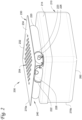
- FIG. 1 depicts a perspective view of an example fume extractor 100 consistent with some embodiments.
- the fume extractor 100 is generally configured to extract fumes from a work area.
- the fume extractor 100 generally has an extractor housing 110, a diffusion plate 130 coupled to the extractor housing 110, and a hose 120 coupled to the extractor housing 110.
- the extractor housing 110 is generally configured to contain various components.
- the extractor housing 110 houses at least a fan and a filter (not currently depicted).
- the extractor housing 110 generally defines an outlet 106 of the fume extractor 100.
- the extractor housing 110 can be constructed of various types of materials and combinations of materials.
- the extractor housing 110 is a plastic.
- the extractor housing 110 is a molded plastic.
- the extractor housing 110 is constructed of metal.
- the extractor housing 110 is configured to be portable.
- the extractor housing 110 can have a handle (not currently depicted) such that a user can carry the fume extractor 100.
- the extractor housing 110 can be openable and re-closeable such that a user can access the interior of the extractor housing 110 to, for example, replace or adjust components.
- the hose 120 generally defines a first inlet 102 of the fume extractor 100.
- the hose 120 defines an airflow pathway 121 into the extractor housing 110.
- the hose 120 defines an airflow pathway 121 to the fan disposed in the extractor housing 110.
- the hose 120 can be coupled to the extractor housing 110 about a first housing opening 112 (represented with a dotted line).
- the hose 120 is generally configured to be used by a user as a point-of-use fume extractor.
- the first inlet 102 can be referred to as a point-of-use extractor inlet.
- a distal end 122 of the hose 120 is configured to be positioned adjacent to a work surface.
- the distal end 122 of the hose 120 can have a securing device 124 such as a clamp, brace, or mount that is configured to secure the distal end 122 of the hose 120 to a work surface.
- a magnetic mount is coupled to the distal end 122 of the hose 120 to magnetically couple the distal end 122 of the hose 120 to a work surface.
- the hose 120 generally has sufficient flexibility to be wound about a hose channel 140 for storage (as will be described in more detail below), un-wound from the hose channel 140, and be positioned in various locations and orientations relative to the extractor housing 110 to accommodate a variety of work surfaces and environments.
- the hose 120 can be constructed of a flexible plastic or rubber.
- the hose 120 can be constructed of a plurality of rigid segments that are joined at flexible joints.
- the hose 120 can have a length of at least 60.96 cm (2 feet). In some embodiments the hose 120 has a length ranging from 30, 48 cm (1 foot) to 243,84 cm (8 feet).
- the diffusion plate 130 generally defines a second inlet 104.
- the diffusion plate 130 is configured to diffuse the airflow through the second inlet 104.
- the diffusion plate 130 defines a plurality of openings 132 that cumulatively define the second inlet 104 of the fume extractor 100.
- the diffusion plate 130 is generally configured to facilitate zone extraction.
- the second inlet 104 can be referred to as a zone extraction inlet.
- the diffusion plate 130 is configured to be an inlet for backdraft extraction.
- the diffusion plate 130 is configured to be an inlet for downdraft extraction.
- the diffusion plate 130 is positioned by a user to selectively achieve backdraft extraction or downdraft extraction.
- the fume extractor 100 is positioned by a user in a workstation to selectively achieve backdraft extraction or downdraft extraction, which will be described in more detail, below.
- the diffusion plate 130 is configured to selectively define a work surface for welding operations.
- the diffusion plate 130 has a main surface 134 that is substantially planar, where the main surface 134 defines the plurality of openings 132.
- Each of the plurality of openings 132 can be circular, in various embodiments. In some such embodiments, each of the plurality of openings 132 have a diameter of at least 0.9525 cm (3/8-inch), although other diameters are possible, as well. In various embodiments, each of the plurality of openings 132 can be threaded to receive mating fasteners such that the diffusion plate 130 can be used as a fixture table.
- the diffusion plate 130 can be constructed of an electrically conductive material, such as aluminum. In some embodiments, the diffusion plate 130 is constructed of steel. The diffusion plate 130 can have a thickness ranging from 0.0254 cm (0.01 inches) to 3.81 cm (1.5 inches) or from 0.0635 cm (0.025 inches) to 2.032 cm (0.80 inches). In some particular embodiments, the diffusion plate 130 can be at least 0.635 cm (0.25 inches) thick. In the current example, the diffusion plate 130 defines plate flanges 136a-c extending substantially orthogonally from the main surface 134, where "substantially orthogonally" is used to mean within +/- 5° from orthogonal.
- the diffusion plate 130 defines a plurality of plate flanges 136 along each side of the main surface 134.
- the plate flanges 136a-c each extend towards the extractor housing 110.
- the plate flanges 136 a-c will be described in more detail, below.
- Zone extraction which is enabled by the diffusion plate 130, can be distinguished from point-of-use extraction, which is enabled by the hose 120.
- zone extraction and point-of-use extraction can be differentiated based on the intake area defined by the inlet of the fume extractor 100.
- An intake area of less than 510.9667 cm 2 (79.2 in 2 ) will generally be considered point-of-use extraction, and an intake area of greater than 510.9667 cm 2 (79.2 in 2 ) will generally be considered zone extraction.
- Zone extraction can also be distinguished from point-of-use extraction based on the capture velocity, where the capture velocity is the velocity of the air passing through the intake area.
- the first inlet 102 defined by the hose 120 generally has an intake area A 1 that is less than about 510.9667cm 2 (79.2 in 2 ), and the second inlet 104 defined by the diffusion plate 130 generally has an intake area A 2 that is greater than about 510.9667 cm 2 (79.2 in 2 ).
- the intake area A 2 of the second inlet 104 is calculated based on the outer dimensions, specifically the length L and the width W, of the plurality of openings 132.
- the first inlet 102 has an intake area A 1 that is less than 322.58cm 2 (50 in 2 ).
- the first inlet 102 has an intake area A 1 that ranges from 129.032 cm 2 (20 in 2 ) to 258.064 cm 2 (40 in 2 ).
- the second inlet 104 has an intake area A 2 that is greater than or equal to 967.74 cm 2 (150 in 2 ).
- the second inlet 104 has an intake area A 2 that ranges from about 1,290.32 cm 2 (200 in 2 ) to 2,580.64 cm 2 (400 in 2 ).
- the fan disposed in the extractor housing 110 is configured to be in communication with the first inlet 102, the second inlet 104, and the outlet 106.
- the fan selectively generates airflow from the first inlet 102 and/or the second inlet 104 through the outlet 106.
- the fan simultaneously connects the first inlet 102 and the second inlet 104 to the outlet 106.
- the first inlet 102 and the second inlet 104 can be arranged in parallel or in a series.
- the fan alternately connects the first inlet 102 or the second inlet 104 to the outlet 106.
- a valve can be used to selectively fluidly couple the fan with the first inlet 102 or the second inlet 104, which is described in more detail with reference to FIG. 8 .
- the first inlet 102 being in communication with the outlet 106 and the second inlet 104 being in communication with the outlet 106 are mutually exclusive.
- the fume extractor 100 has a first supporting surface 160 that is opposite the diffusion plate 130 relative to the extractor housing 110.
- the first supporting surface 160 is generally configured to selectively rest on a planar surface, such as a tabletop or a floor.
- a "supporting surface” is defined herein as a structure that allows the fume extractor 100 to stand on its own on a generally horizontal surface.
- the first supporting surface 160 defines a first support plane 162 that is opposite the main surface 134 relative to the extractor housing 110. In various embodiments the first support plane 162 is parallel to the main surface 134 of the diffusion plate 130. In various embodiments the main surface 134 of the diffusion plate 130 is configured to form a substantially horizontal work surface when the first supporting surface 160 rests on a tabletop or floor.
- the first supporting surface 160 is defined by a plurality of feet 154a, 154b extending outward from the extractor housing 110 away from the diffusion plate 130. While in the current embodiment, the plurality of feet 154a, 154b are two feet defined by two brackets, other numbers of feet and/or brackets can be used. In some embodiments, four brackets can be coupled to the extractor housing that each define one foot extending away from the diffusion plate. In some embodiments, two brackets can be coupled to the extractor housing that each define two feet.
- the second support plane 172 can be substantially orthogonal to the first supporting plane 162.
- the second support plane 172 can be generally orthogonal to the main surface 134 of the diffusion plate 130.
- the main surface 134 of the diffusion plate 130 is configured to form a substantially vertical surface when the second supporting surface 170 rests on a tabletop or floor. "Substantially vertical” is intended to mean within 5° of a vertical orientation.
- the second supporting surface 170 is cumulatively defined by the first bracket 150a, the second bracket 150b, and the diffusion plate 130.
- a first bracket flange 152a defined by the first bracket 150a, a second bracket flange 152b defined by the second bracket 150b, and a first plate flange 136a defined by the diffusion plate 130 cumulatively define the second supporting surface 170.
- a user can place the fume extractor 100 on a table such that the second supporting surface 170 rests on the table. Such a configuration positions the second inlet 104 of the diffusion plate 130 for backdraft extraction.
- the fume extractor 100 can have up to five supporting surfaces, corresponding to the five sides of the fume extractor 100 other than the side defined by the diffusion plate 130.
- Each of the supporting surfaces can be similar to the first supporting surface 160 and the second supporting surface 170 described above. Alternate configurations for the supporting surfaces are also contemplated, which will be described below in association with other examples.
- the fume extractor 100 generally defines a hose channel 140 that is configured to selectively receive a length of the hose 120.
- the hose channel 140 stores the hose 120 when the hose 120 is not in use.
- the hose channel 140 extends about a periphery of the fume extractor 100 and, in particular, about a periphery of the extractor housing 110.
- the hose channel 140 is generally sized such that the hose 120, when in a stored position, does not interfere with contact between each of the supporting surfaces and the planar surface.
- the hose 120 is configured to be retained within the hose channel 140 within the outer perimetric boundaries of the fume extractor 100. As such, the depth and width of the hose channel 140 exceeds the diameter of the hose 120.
- the barrier can be coupled to the hose 120 and can be positionable to reversibly obstruct the first inlet 102.
- the barrier can be cover coupled to the hose at a hinged connection and can be pivoted between a first position where the first inlet 102 is obstructed and a second position where the first inlet 102 is unobstructed.
- the performance of the fan 280 is adjustable by a user.
- the fan speed is adjustable, and in some embodiments the flow rate of the fan is adjustable with a flow rate regulator. Embodiments incorporating a flow rate regulator will be described in more detail with reference to FIG. 8 , below.
- the hose 220 generally defines a first inlet 202 of the fume extractor 200, where the first inlet 202 is particularly visible in FIG. 4 .
- the hose 220 defines an airflow pathway 221 into the extractor housing 210.
- the hose 220 defines an airflow pathway 221 to the fan 280 disposed in the extractor housing 210.
- the fan 280 is configured direct airflow from the first inlet 202 to the outlet 206.
- the hose 220 can be coupled to the extractor housing 210 about a first housing opening 212 (represented with a dotted line in FIG. 4 ).
- a proximal end 223 of the hose 220 is coupled to a first connector tube 226 that passes through the first housing opening 212.
- a distal end 222 of the hose 220 is releasably coupled to a second connector tube 228.
- the diffusion plate 230 defines the plurality of openings 232 through the main surface 234.
- the plurality of openings 232 can have similar configurations to those discussed above with reference to FIG. 1 .
- the diffusion plate 230 can also have similar configurations to those discussed above with reference to FIG. 1 .
- the diffusion plate 230 does not have perimetric flanges extending substantially orthogonally to the main surface 234, but such flanges could be incorporated in the diffusion plate 230 some variations.
- a perimeter region 236 of the diffusion plate 230 surrounds the plurality of openings 232 and is coupled to a rim 254 of the diffusion plate housing 250.
- the rim 254 of the diffusion plate housing 250 surrounds the airflow volume 252.
- the diffusion plate housing 250 and the extractor housing 210 can be separate components in some embodiments, and in other embodiments the diffusion plate housing 250 and the extractor housing 210 can be portions of a single component.
- the hose 220 is used in both point-of-use extraction and zone extraction.
- the hose 220 is coupled to the second connector tube 228 and the fan 280 is in communication with the first inlet 202, the second inlet 204, and the outlet 206.
- the distal end 222 of the hose 220 is released from the second connector tube 228, and the fan 280 is in communication with the first inlet 202 and the outlet 206.
- the fan selectively generates airflow from the first inlet 202 through the outlet 206, and optionally through the second inlet 204.
- the fume extractor 200 defines a hose channel 240 that is configured to selectively receive a length of the hose 220.
- the hose channel 240 stores the hose 220 when the hose 220 is coupled to the second connector tube 228 for zone extraction and when the fume extractor 200 is not in use.
- the hose channel 240 extends about a periphery of the fume extractor 200 and, in particular, about a periphery of the diffusion plate housing 250.
- the hose 220 is configured to be retained within the hose channel 240 within the outer perimetric boundaries of the fume extractor 200.
- the hose channel 240 is cumulatively defined by the diffusion plate housing 250 and the extractor housing 210.
- the hose channel 240 is defined between the diffusion plate 230 and the extractor housing 210.
- the extractor housing 210 and the diffusion plate housing 250 form hose guides to retain the position of the hose 220 about the diffusion plate housing 250.
- the fume extractor 200 has a first supporting surface 260 that is opposite the diffusion plate 230 relative to the extractor housing 210.
- the first supporting surface 260 is defined by the extractor housing 210. More particularly, the first supporting surface 260 is completely defined by the extractor housing 210.
- the first supporting surface 260 is generally configured to selectively rest on a planar surface, such as a tabletop or a floor.
- the first supporting surface 260 defines a first support plane 262 that is opposite the main surface 234 relative to the extractor housing 210.
- the first supporting surface 260 is parallel to the main surface 234 of the diffusion plate 230.
- the main surface 234 of the diffusion plate 230 is configured to form a substantially horizontal work surface when the first supporting surface 260 rests on a tabletop or floor.
- brackets and/or feet, or other structures can be coupled to the extractor housing 210 to form the first supporting surface.
- the fume extractor 200 has a second supporting surface 270a, 270b that is generally orthogonal to the diffusion plate 230, which is best visible in FIG. 5 .
- the second supporting surface 270a, 270b is generally configured to selectively rest on a planar surface, such as a tabletop or a floor.
- the second supporting surface 270a, 270b defines a second support plane 272 that is generally orthogonal to the main surface 234 of the diffusion plate 230.
- the second support plane 272 is generally coplanar with the planar surface on which the second supporting surface 270a, 270b is configured to selectively rest upon.
- the second support plane 272 can be substantially orthogonal to the first support plane 262 in some embodiments.
- the second support plane 272 is about 95° from the first support plane 262, but the second support plane 272 can range from about 80° to about 100° from the first support plane 262.
- the main surface 234 of the diffusion plate 230 is configured to form a generally vertical surface when the second supporting surface 270a, 270b rests on a tabletop or floor.
- the second supporting surface 270a, 270b is cumulatively defined by (1) an edge of the diffusion plate 230 (270a) and (2) a portion of a sidewall 214 of the extractor housing 210.
- a user can place the fume extractor 200 on a table such that the second supporting surface 270 rests on the table. Such a configuration positions the second inlet 204 of the diffusion plate 230 for backdraft extraction.
- the first supporting surface 260 and/or the second supporting surface 270a, 270b are configured to increase traction between the fume extractor and the planar surface.
- the first supporting surface 260 and/or the second supporting surface 270a, 270b can have surface irregularities that results in a relatively increased surface roughness compared to a smooth surface.
- the first supporting surface 260 and the second supporting surface 270a, 270b are configured to be electrically conductive to enable welding operations.
- an electrically conductive wire 274 can electrically couple to the diffusion plate 230 to one or more of the supporting surfaces, such as the wire 274 visible in FIG. 4 .
- the fume extractor 200 can have up to five supporting surfaces, corresponding to the five sides of the fume extractor 200 other than the side defined by the diffusion plate 230.
- Each of the supporting surfaces can have a similar construction or a different construction to the first supporting surface 260 and the second supporting surface 270a, 270b described above. Alternate configurations for the supporting surfaces are also contemplated.
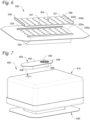
- FIG. 6 is a perspective view of another example diffusion plate 330 consistent with various embodiments.
- the diffusion plate 330 has a fixed plate 330a and a sliding plate 330b that are configured to selectively define a second inlet 304 of a fume extractor.
- the fixed plate 330a is configured to be coupled to an extractor housing or a diffusion plate housing consistent with those described above.
- the fixed plate 330a defines a fixed plurality of openings 332a that partially define the second inlet 304 of the fume extractor.
- the sliding plate 330b also defines a sliding plurality of openings 332b that also partially define the second inlet 304 of the fume extractor.
- the sliding plate 330b is slidably coupled to the fixed plate 330a to define a first position where the second inlet 304 is unobstructed and a second position with the second inlet 304 is obstructed.
- the fixed plate 330a defines slide channels 334 that slidably receive corresponding edges 331 of the sliding plate 330b.
- the sliding plate 330b can define grasping features 336 that are configured to be grasped by a user to slide the sliding plate 330b relative to the fixed plate 330a.
- a user slides the sliding plate 330b along the fixed plate 330a to bring the sliding plurality of openings 332b into alignment with the fixed plurality of openings 332a to open the second inlet 304.
- a valve can selectively obstruct the airflow pathway defined by the hose of the fume extractor (such as a hose disclosed with reference to FIG. 1 ) to maximize airflow through the second inlet 304.
- the sliding plate 330b can be slid along the fixed plate 330a to obstruct the fixed plurality of openings 332a with the portions of the sliding plate 330b that are between the sliding openings 332b, which obstructs the second inlet 304.
- the fume extractor can be used for point-of-use extraction.
- the hose incorporates a shut-off valve
- the shut-off valve can be opened to open the airflow pathway through the hose and a first inlet defined by the hose (such as described earlier) can be positioned proximate a work surface for extraction.
- the diffusion plate 330 can have a variety of alternate configurations.
- the diffusion plate can have a flap that is manually positioned over the plurality of openings to obstruct the second inlet to modify the fume extractor in a point-of-use configuration.
- the flap can be pivotably coupled to the diffusion plate 330.
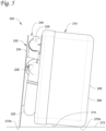
- FIG. 7 depicts a bottom exploded view of another example fume extractor 400 consistent with some examples.
- the fume extractor 400 has an extractor housing 410, a hose (not currently visible), and a diffusion plate 430 consistent with examples discussed throughout this paper.
- the extractor housing 410 defines an outlet 406 of the fume extractor 400.
- a damper 450 can be coupled to the extractor housing 410 over the outlet 406 to reduce noise escaping from the housing that can be generated by the fan.
- the damper 450 forms a casing 452 around the outlet 406 and defines a vent opening 454 that is unaligned with the outlet 406 but is in fluid communication with the vent opening 454.
- the damper 450 has a perimetric flange 456 extending around the casing 452.
- the perimetric flange 456 is spaced from the extractor housing 410 to define a cord storage area 458 about the casing 452 between the perimetric flange 456 and the extractor housing 410.
- the cord storage area 458 is configured to accommodate a power cord, such as a power cord for a fan in the extractor housing 410.
- Fume extractors consistent with the technology disclosed herein can incorporate additional features or modifications to help lessen noise associated with operation of fume extractor.
- the fan and filter do not make direct contact with the extractor housing.
- acoustic dampening material can be disposed in the extractor housing between the fan and/or the filter and the extractor housing.
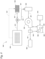
- FIG. 8 is a schematic of an example fume extractor 500 consistent with embodiments.
- the fume extractor 500 has a first inlet 502, a second inlet 504, and a fan 530.
- the fume extractor 500 is configured to extract fumes from a work area.
- the first inlet 502 is generally a point-of-use extraction inlet and the second inlet 504 is a zone extraction inlet, each of which are described in detail herein above.
- Each of the first inlet 502 and the second inlet 504 are configured to be in fluid communication with the fan 530 via an airflow pathway 501.
- first inlet 502 and the second inlet 504 are arranged in parallel relative to the fan 530, such as described above with reference to FIGS. 1 and 6 .
- a valve 510 can be disposed along the airflow pathway 501 to selectively establish fluid communication between either (1) the fan 530 and the first inlet 502 (for point-of-use extraction) or (2) the fan 530 the second inlet 504 (for zone extraction).
- the valve 510 can be manually or electrically actuated.
- an obstruction such as a barrier, sliding plate, shut-off valve, flap, cover, or the like, can be incorporated in the fume extractor 500 that is configured to selectively obstruct one of the first inlet 502 and the second inlet 504.
- Such an obstruction can be used in combination with or alternate to the three-way valve 510 depicted in the schematic of FIG. 8 .
- first inlet 502 and the second inlet 504 are arranged in a series relative to the fan 530, such as described above with reference to FIGS. 2-5 .
- the first inlet 502 is in fluid communication with the fan 530 and the second inlet 504 is selectively in fluid communication with the first inlet 502 for zone extraction.
- the second inlet 504 is decoupled from the first inlet 502 for point-of-use extraction.
- An airflow pathway 501 selectively fluidly couples the second inlet 504 to the first inlet 502, and the airflow pathway 501 couples the first inlet 502 to the fan 530.
- a filter 520 is operatively disposed in the airflow pathway 501 between the fan 530 and the first and second inlet 502, 504.
- the filter 520 can be consistent with filters generally discussed herein.
- a damper 580 can be disposed along the airflow pathway 501 that is configured to reduce noise generated from the fan 530. The damper 580 can be consistent with those discussed above.
- a flow rate regulator 560 is in operative communication with the fan 530.
- the flow rate regulator 560 is generally configured to establish and maintain a particular flow rate of air through the airflow pathway 501 by adjusting fan 530 operation.
- the flow rate of the fan 530 can be set by a user through a user interface 570 in communication with the flow rate regulator 560.
- a sensor 540 disposed in the airflow pathway 501 is configured to sense flow rate.
- the flow rate regulator 560 is configured to read the data from the sensor 540 and adjust the fan speed as appropriate to maintain the flow rate set by the user.
- the flow rate regulator 560 increases the fan speed to maintain the same flow rate.
- the flow rate regulator can provide a notification to a user to replace the filter.
- the senor 540 is currently depicted downstream of the fan 530, in some embodiments the sensor 540 is positioned upstream of the fan 530. In some embodiments the sensor can be positioned within the fan itself. Other configurations are certainly contemplated.
- the flow rate regulator 560 can have a processor 562 that receives various inputs and executes one or more computer programs or applications stored in a memory 564.
- the memory 564 can have computer-readable instructions or applications that, when executed, e.g., by the processor 562, cause the regulator 560 to perform various calculations and issue commands.
- the processor 562 and memory 564 can define a computing apparatus operable to process input data and generate the desired output to one or more components/devices such as the fan 530 and the user interface 570.
- the functionality of the flow rate regulator 560 can be implemented in any manner known to one skilled in the art.
- the memory 564 can include any volatile, non-volatile, magnetic, optical, and/or electrical media, such as a random-access memory (RAM), read-only memory (ROM), non-volatile RAM (NVRAM), electrically-erasable programmable ROM (EEPROM), flash memory, and/or any other digital media. While shown as both being incorporated into the flow rate regulator 560, the memory 564 and the processor 562 could be contained in separate modules.
- the processor 562 can have any one or more of a microprocessor, a controller, a digital signal processor (DSP), an application specific integrated circuit (ASIC), a field-programmable gate array (FPGA), and/or equivalent discrete or integrated logic circuitry.
- the processor 562 can include multiple components, such as any combination of one or more microprocessors, one or more controllers, one or more DSPs, one or more ASICs, and/or one or more FPGAs, as well as other discrete or integrated logic circuitry.
- the functions attributed to the controller/processor herein may be embodied as software, firmware, hardware, or any combination thereof.
- a spark arrestor can be incorporated in the fume extractor 500.
- the spark arrestor can be disposed in the airflow pathway 501 upstream of the filter 520.
- the spark arrestor can be disposed in the airflow pathway 501 between the first inlet 502 and filter 520 and between the second inlet 504 and the filter 520.
- the spark arrestor can be constructed of flame retardant materials.
- components of a fume extractor 500 consistent with the current disclosure can be constructed of flame retardant materials.
- the filter 520 can incorporate filter media having a flame retardant disposed thereon.
- the phrase “configured” describes a system, apparatus, or other structure that is constructed to perform a particular task or adopt a particular configuration.
- the word “configured” can be used interchangeably with similar words such as “arranged”, “constructed”, “manufactured”, and the like.
Landscapes
- Engineering & Computer Science (AREA)
- Physics & Mathematics (AREA)
- Mechanical Engineering (AREA)
- Optics & Photonics (AREA)
- Plasma & Fusion (AREA)
- Filtering Of Dispersed Particles In Gases (AREA)
- Prevention Of Fouling (AREA)
Claims (15)
- Rauchentnahmeeinheit, umfassend:ein Entnahmeeinheitsgehäuse (110; 210; 410), welches einen Auslass (106; 206; 406) der Rauchentnahmeeinheit (100; 200; 400; 500) definiert;einen Schlauch (120; 220), welcher an das Entnahmeeinheitsgehäuse (110; 210; 410) gekoppelt ist, wobei der Schlauch (120; 220) ein distales Ende (122; 222) aufweist, welches einen ersten Einlass (102; 202; 502) der Rauchentnahmeeinheit (100; 200; 400; 500) definiert;eine Diffusionsplatte (130; 230; 330; 430), welche an das Entnahmeeinheitsgehäuse (110; 210; 410) gekoppelt ist, wobei die Diffusionsplatte (130; 230; 330; 430) eine Mehrzahl von Öffnungen (132; 232; 332) definiert, welche einen zweiten Einlass (104; 204; 304; 504) der Rauchentnahmeeinheit (100; 200; 400; 500) kumulativ definieren;ein Gebläse (280; 530), welches in dem Entnahmeeinheitsgehäuse (110; 210; 410) angeordnet ist, wobei das Gebläse (280; 530) dazu eingerichtet ist, jeden von dem ersten Einlass (102; 202; 502) und dem zweiten Einlass (104; 204; 304; 504) mit dem Auslass (106; 206; 406) zu verbinden;eine erste Unterstützungsfläche (160; 260), gegenüberliegend der Diffusionsplatte (130; 230; 330; 430) relativ zu dem Entnahmeeinheitsgehäuse (110; 210; 410); undeine zweite Unterstützungsfläche (170; 270a; 270b), welche sich von 80° zu 100° zu der Diffusionsplatte (130; 230; 330; 430) befindet, wobei die erste Unterstützungsfläche (160; 260) und die zweite Unterstützungsfläche (170; 270a; 270b) dazu eingerichtet sind, auf einer planaren Fläche selektiv zu liegen,dadurch gekennzeichnet, dassdie Rauchentnahmeeinheit (100; 200; 400; 500) einen Schlauchkanal (140; 240) definiert, welcher dazu eingerichtet ist, den Schlauch (120; 220) selektiv aufzunehmen, und dadurch, dass die Rauchentnahmeeinheit (100; 200; 400; 500) eine Schlauchführung (142a, 142b) umfasst.
- Rauchentnahmeeinheit nach Anspruch 1, wobei sich der Schlauchkanal (140; 240) um einen Umfang der Rauchentnahmeeinheit (100; 200; 400; 500) erstreckt.
- Rauchentnahmeeinheit nach einem der Ansprüche 1-2, wobei der Schlauchkanal (140; 240) zwischen dem Entnahmeeinheitsgehäuse (110; 210; 410) und der Diffusionsplatte (130; 230; 330; 430) definiert ist.
- Rauchentnahmeeinheit nach einem der Ansprüche 1-3, wobei der Schlauch (120; 220) eine Einnahmefläche von weniger als 510.9667 cm2 ( 79.2 in2) definiert; und/oder
wobei die Diffusionsplatte (130; 230; 330; 430) eine Einnahmefläche von größer als 510.9667 cm2( 79.2 in2) definiert. - Rauchentnahmeeinheit nach einem der Ansprüche 1-4, welche ferner einen Filter (290; 520) umfasst, welcher in dem Entnahmeeinheitsgehäuse (110; 210; 410) in einem Luftstromweg (121; 221; 501) zwischen den ersten und zweiten Einlässen und dem Auslass (106; 206; 406) angeordnet ist.
- Rauchentnahmeeinheit nach einem der Ansprüche 1-5, welche ferner ein elektrisch leitfähiges Kabel (274) umfasst, welches die Diffusionsplatte (130; 230; 330; 430) mit der ersten Unterstützungsfläche (160; 260) und der zweiten Unterstützungsfläche (170; 270a; 270b) elektrisch koppelt.
- Rauchentnahmeeinheit nach einem der Ansprüche 1-6, wobei jede aus der Mehrzahl von Öffnungen (132; 232; 332) mit einem Gewinde versehen ist.
- Rauchentnahmeeinheit nach einem der Ansprüche 1-7, wobei die erste Unterstützungsfläche (160; 260) durch eine Mehrzahl von Füßen (154) definiert ist, welche sich von dem Entnahmeeinheitsgehäuse (110; 210; 410) weg von der Diffusionsplatte (130; 230; 330; 430) nach außen erstrecken.
- Rauchentnahmeeinheit nach einem der Ansprüche 1-8, wobei die zweite Unterstützungsfläche (170; 270a; 270b) teilweise durch das Entnahmeeinheitsgehäuse (110; 210; 410) definiert ist und/oder wobei die erste Unterstützungsfläche (160; 260) komplett durch das Entnahmeeinheitsgehäuse (110; 210; 410) definiert ist.
- Rauchentnahmeeinheit nach einem der Ansprüche 1-9, wobei die Diffusionsplatte (130; 230; 330; 430) Aluminium umfasst, welches eine Dicke von wenigstens 0.635 cm (0.25 Inches) aufweist; und/oder
wobei die Öffnungen (132; 232; 332) in der Diffusionsplatte (130; 230; 330; 430) jeweils kreisförmig sind, mit einem Durchmesser von wenigstens 0.9525 cm (3/8-Inches). - Rauchentnahmeeinheit nach einem der Ansprüche 1-10, wobei der Schlauch (120; 220) einen Luftstromweg (121; 221; 501) definiert und ein Hindernis umfasst, welches den Luftstromweg (121; 221; 501) selektiv versperrt, auf Empfangen des Schlauchs (120; 220) von dem Schlauchkanal (140; 240) hin.
- Rauchentnahmeeinheit nach einem der Ansprüche 1-11, welche ferner einen Flussratenregulator (560) umfasst, welcher dazu eingerichtet ist, einen Luftstrom zu messen und zu regulieren.
- Rauchentnahmeeinheit nach einem der Ansprüche 1-12, wobei der erste Einlass (202; 502) und der zweite Einlass (204; 504) in Serie angeordnet sind, wobei der zweite Einlass (204; 504) selektiv in Fluidkommunikation mit dem ersten Einlass (202; 502) für eine Zonenextraktion steht; wobei der zweite Einlass (204; 504) von dem ersten Einlass (202; 502) für eine Entnahmestellenextraktion entkoppelt ist; oder
wobei der erste Einlass (102; 502) und der zweite Einlass (104; 304; 504) parallel angeordnet sind. - Rauchentnahmeeinheit nach einem der Ansprüche 1-13, wobei die Diffusionsplatte (130; 230; 330; 430) eine fixierte Platte (330a), welche eine fixierte Mehrzahl von Öffnungen (332a) definiert, und eine gleitende Platte (330b) umfasst, welche eine gleitende Mehrzahl von Öffnungen (332b) definiert, wobei die gleitende Platte (330b) mit der fixierten Platte (330a) gleitend gekoppelt ist, um die fixierte Mehrzahl von Öffnungen (332a) mit der gleitenden Mehrzahl von Öffnungen (332b) selektiv auszurichten.
- Rauchentnahmeeinheit nach einem der Ansprüche 1-14, wobei der erste Einlass (102; 202; 502) in selektiver Fluidkommunikation mit dem zweiten Einlass (104; 204; 304; 504) steht.
Applications Claiming Priority (2)
| Application Number | Priority Date | Filing Date | Title |
|---|---|---|---|
| US201962944162P | 2019-12-05 | 2019-12-05 | |
| PCT/US2020/063002 WO2021113437A1 (en) | 2019-12-05 | 2020-12-03 | Fume extractor |
Publications (3)
| Publication Number | Publication Date |
|---|---|
| EP4069443A1 EP4069443A1 (de) | 2022-10-12 |
| EP4069443C0 EP4069443C0 (de) | 2024-10-09 |
| EP4069443B1 true EP4069443B1 (de) | 2024-10-09 |
Family
ID=74046164
Family Applications (1)
| Application Number | Title | Priority Date | Filing Date |
|---|---|---|---|
| EP20829441.3A Active EP4069443B1 (de) | 2019-12-05 | 2020-12-03 | Dunstabzugsvorrichtung |
Country Status (4)
| Country | Link |
|---|---|
| US (1) | US12440930B2 (de) |
| EP (1) | EP4069443B1 (de) |
| CN (1) | CN115052692A (de) |
| WO (1) | WO2021113437A1 (de) |
Families Citing this family (1)
| Publication number | Priority date | Publication date | Assignee | Title |
|---|---|---|---|---|
| EP4069443B1 (de) | 2019-12-05 | 2024-10-09 | Donaldson Company, Inc. | Dunstabzugsvorrichtung |
Family Cites Families (36)
| Publication number | Priority date | Publication date | Assignee | Title |
|---|---|---|---|---|
| US2283140A (en) * | 1941-02-28 | 1942-05-12 | Allis Chalmers Mfg Co | Welding work positioner |
| US4512245A (en) * | 1982-09-24 | 1985-04-23 | Adsorbent Products Inc. | Portable point source adsorber |
| US4860644A (en) | 1988-02-29 | 1989-08-29 | Donaldson Company, Inc. | Articulatable fume exhauster trunk |
| US5362036A (en) * | 1993-07-23 | 1994-11-08 | Halliburton Company | Modular welding fixture apparatus |
| US5511764A (en) | 1994-11-29 | 1996-04-30 | A. A. Doerr Mercantile Co. | Self-exhausting welding station |
| US6607573B1 (en) | 1997-02-06 | 2003-08-19 | Northrop Grumman Corporation | Portable air pollution control apparatus |
| US6444002B1 (en) * | 1999-09-14 | 2002-09-03 | Billy Mai | Nail salon air purification system |
| DE60035213T2 (de) | 1999-11-05 | 2007-09-27 | Delaware Capital Formation, Inc., Wilmington | Rauchabzugvorrichtung und anordnung |
| US6395047B1 (en) | 2001-02-16 | 2002-05-28 | William C. Smith | Portable airborne contamination control system including a main and remote unit |
| TW549172U (en) * | 2001-12-13 | 2003-08-21 | Hao-Fong Lin | Multi-purpose welding worktable |
| US6802266B2 (en) * | 2002-05-21 | 2004-10-12 | Meng-Chieh Cheng | Work table with a sawdust collecting mechanism |
| US7712182B2 (en) * | 2003-07-25 | 2010-05-11 | Milwaukee Electric Tool Corporation | Air flow-producing device, such as a vacuum cleaner or a blower |
| EP1832354A1 (de) | 2006-03-09 | 2007-09-12 | Yuan-Tai Cheng | Gasfilter zur Elektroschweissung |
| US7513922B2 (en) | 2006-03-29 | 2009-04-07 | Yuan-Tai Cheng | Air filter for electric welding |
| US20080276806A1 (en) | 2007-05-09 | 2008-11-13 | Chieh-Yuan Cheng | Welding smog disposing machine |
| US8460417B2 (en) * | 2008-11-11 | 2013-06-11 | Great Lakes Air Systems, Inc. | Portable air filtration system |
| US20100282728A1 (en) * | 2009-05-11 | 2010-11-11 | Lincoln Global, Inc. | Power source with fume extractor for welding |
| JP5513015B2 (ja) * | 2009-05-29 | 2014-06-04 | 白光株式会社 | 吸煙装置 |
| CN101721166B (zh) * | 2009-12-23 | 2011-08-31 | 苏州斯普科林电器有限公司 | 卧式立式两用吸尘器 |
| TWI432945B (zh) * | 2010-01-18 | 2014-04-01 | Wistron Corp | 流阻裝置 |
| CN102039507A (zh) * | 2011-01-18 | 2011-05-04 | 陈凌 | 一种焊接夹具平台 |
| US9846439B2 (en) * | 2012-05-04 | 2017-12-19 | Illinois Tool Works Inc. | Automatic flow regulator for fume gun |
| KR101417449B1 (ko) * | 2012-12-05 | 2014-07-08 | 김성도 | 휴대용 흄 집진기 |
| CN103386563A (zh) | 2013-07-22 | 2013-11-13 | 力帆实业(集团)股份有限公司 | 一种焊接工作台 |
| CN204487600U (zh) * | 2014-12-23 | 2015-07-22 | 南京嘉翼精密机器制造股份有限公司 | 一种立卧两用式单轴变位机 |
| US10137485B2 (en) | 2015-01-06 | 2018-11-27 | Lincoln Global, Inc. | Integrated workpiece positioning system with integral fume extraction system |
| US11530826B2 (en) | 2015-07-16 | 2022-12-20 | Illinois Tool Works Inc. | Extractor with segmented positive pressure airflow system |
| US10857550B2 (en) | 2016-03-21 | 2020-12-08 | Thomas Huntley | Low profile dust separator |
| CN205732091U (zh) * | 2016-06-20 | 2016-11-30 | 台州市博赛尼清洁设备有限公司 | 一种立卧式两用高压清洗机 |
| CN106137025A (zh) * | 2016-08-18 | 2016-11-23 | 苏州凯丽达电器有限公司 | 一种可收纳软管的行走吸尘器 |
| CN207785060U (zh) * | 2017-06-19 | 2018-08-31 | 上海未来伙伴机器人有限公司 | 一种吸尘软管自动收纳装置及服务机器人 |
| CN208138164U (zh) * | 2018-02-12 | 2018-11-23 | 慈溪市龙山博越电子商务经营部 | 立卧两用迷你风扇 |
| CA3001031A1 (en) * | 2018-04-11 | 2019-10-11 | Luke Woloszczuk | Combination vacuum, tile cutting and dust collection system |
| US11191343B2 (en) * | 2018-05-11 | 2021-12-07 | Healthy Air, Inc. | Source capture apparatus for manicure tables |
| CN208662886U (zh) | 2018-09-05 | 2019-03-29 | 合肥菲斯特激光科技有限公司 | 一种焊接双极板用除尘装置 |
| EP4069443B1 (de) | 2019-12-05 | 2024-10-09 | Donaldson Company, Inc. | Dunstabzugsvorrichtung |
-
2020
- 2020-12-03 EP EP20829441.3A patent/EP4069443B1/de active Active
- 2020-12-03 WO PCT/US2020/063002 patent/WO2021113437A1/en not_active Ceased
- 2020-12-03 US US17/782,517 patent/US12440930B2/en active Active
- 2020-12-03 CN CN202080083817.3A patent/CN115052692A/zh active Pending
Also Published As
| Publication number | Publication date |
|---|---|
| US12440930B2 (en) | 2025-10-14 |
| EP4069443A1 (de) | 2022-10-12 |
| EP4069443C0 (de) | 2024-10-09 |
| US20230001521A1 (en) | 2023-01-05 |
| WO2021113437A1 (en) | 2021-06-10 |
| CN115052692A (zh) | 2022-09-13 |
Similar Documents
| Publication | Publication Date | Title |
|---|---|---|
| US11841023B2 (en) | Blowers having noise reduction features | |
| US8496719B2 (en) | Cyclonic dust collector with flame arrester feature | |
| CN106839139B (zh) | 空气清洁器 | |
| CN107150378B (zh) | 一种无尘台锯 | |
| EP3406286A1 (de) | Systeme zur bereitstellung eines rauscharmen positiven atemwegsdrucks | |
| EP4069443B1 (de) | Dunstabzugsvorrichtung | |
| US4367665A (en) | Sawdust collection system | |
| US6145160A (en) | Tank-type vacuum cleaner | |
| EP1225827B1 (de) | Rauchabzugvorrichtung und anordnung | |
| CA2907407A1 (en) | Portable positive pressure apparatus and method for attenuating the noise emitted therefrom | |
| TW201233471A (en) | Table saw having airflow apparatus | |
| CN105592990A (zh) | 具有灰尘管理的锯片下降电动工具 | |
| CN105783064A (zh) | 具有助吸装置的吸油烟机及抽吸油烟的方法 | |
| US11564539B2 (en) | Central vacuum system | |
| JP2002257097A (ja) | 動力作業機 | |
| KR102055303B1 (ko) | 국소배기장치 | |
| CN115446482A (zh) | 一种角度可调的激光镭雕机吸风装置 | |
| KR101581571B1 (ko) | 압축공기를 이용한 산업용 진공청소기 | |
| JP3165459U (ja) | 送風機 | |
| KR102841306B1 (ko) | 납 연기 흡입기 | |
| CN221575670U (zh) | 一种新型离子风机 | |
| JP6144599B2 (ja) | エアクリーナ | |
| CN216321006U (zh) | 一种三氯化磷尾气处理装置 | |
| CN211633066U (zh) | 一种无尘干磨管道恒压中央集尘装置 | |
| JP2019058249A (ja) | 火災実験設備及び火災実験設備の実験方法 |
Legal Events
| Date | Code | Title | Description |
|---|---|---|---|
| STAA | Information on the status of an ep patent application or granted ep patent |
Free format text: STATUS: UNKNOWN |
|
| STAA | Information on the status of an ep patent application or granted ep patent |
Free format text: STATUS: THE INTERNATIONAL PUBLICATION HAS BEEN MADE |
|
| PUAI | Public reference made under article 153(3) epc to a published international application that has entered the european phase |
Free format text: ORIGINAL CODE: 0009012 |
|
| STAA | Information on the status of an ep patent application or granted ep patent |
Free format text: STATUS: REQUEST FOR EXAMINATION WAS MADE |
|
| 17P | Request for examination filed |
Effective date: 20220517 |
|
| AK | Designated contracting states |
Kind code of ref document: A1 Designated state(s): AL AT BE BG CH CY CZ DE DK EE ES FI FR GB GR HR HU IE IS IT LI LT LU LV MC MK MT NL NO PL PT RO RS SE SI SK SM TR |
|
| RAP3 | Party data changed (applicant data changed or rights of an application transferred) |
Owner name: DONALDSON COMPANY, INC. |
|
| DAV | Request for validation of the european patent (deleted) | ||
| DAX | Request for extension of the european patent (deleted) | ||
| GRAP | Despatch of communication of intention to grant a patent |
Free format text: ORIGINAL CODE: EPIDOSNIGR1 |
|
| STAA | Information on the status of an ep patent application or granted ep patent |
Free format text: STATUS: GRANT OF PATENT IS INTENDED |
|
| INTG | Intention to grant announced |
Effective date: 20240527 |
|
| GRAS | Grant fee paid |
Free format text: ORIGINAL CODE: EPIDOSNIGR3 |
|
| GRAA | (expected) grant |
Free format text: ORIGINAL CODE: 0009210 |
|
| STAA | Information on the status of an ep patent application or granted ep patent |
Free format text: STATUS: THE PATENT HAS BEEN GRANTED |
|
| AK | Designated contracting states |
Kind code of ref document: B1 Designated state(s): AL AT BE BG CH CY CZ DE DK EE ES FI FR GB GR HR HU IE IS IT LI LT LU LV MC MK MT NL NO PL PT RO RS SE SI SK SM TR |
|
| REG | Reference to a national code |
Ref country code: CH Ref legal event code: EP |
|
| REG | Reference to a national code |
Ref country code: DE Ref legal event code: R096 Ref document number: 602020039246 Country of ref document: DE |
|
| REG | Reference to a national code |
Ref country code: IE Ref legal event code: FG4D |
|
| U01 | Request for unitary effect filed |
Effective date: 20241016 |
|
| U07 | Unitary effect registered |
Designated state(s): AT BE BG DE DK EE FI FR IT LT LU LV MT NL PT RO SE SI Effective date: 20241104 |
|
| U20 | Renewal fee for the european patent with unitary effect paid |
Year of fee payment: 5 Effective date: 20241121 |
|
| PG25 | Lapsed in a contracting state [announced via postgrant information from national office to epo] |
Ref country code: IS Free format text: LAPSE BECAUSE OF FAILURE TO SUBMIT A TRANSLATION OF THE DESCRIPTION OR TO PAY THE FEE WITHIN THE PRESCRIBED TIME-LIMIT Effective date: 20250209 Ref country code: HR Free format text: LAPSE BECAUSE OF FAILURE TO SUBMIT A TRANSLATION OF THE DESCRIPTION OR TO PAY THE FEE WITHIN THE PRESCRIBED TIME-LIMIT Effective date: 20241009 |
|
| PG25 | Lapsed in a contracting state [announced via postgrant information from national office to epo] |
Ref country code: ES Free format text: LAPSE BECAUSE OF FAILURE TO SUBMIT A TRANSLATION OF THE DESCRIPTION OR TO PAY THE FEE WITHIN THE PRESCRIBED TIME-LIMIT Effective date: 20241009 |
|
| PG25 | Lapsed in a contracting state [announced via postgrant information from national office to epo] |
Ref country code: NO Free format text: LAPSE BECAUSE OF FAILURE TO SUBMIT A TRANSLATION OF THE DESCRIPTION OR TO PAY THE FEE WITHIN THE PRESCRIBED TIME-LIMIT Effective date: 20250109 |
|
| PG25 | Lapsed in a contracting state [announced via postgrant information from national office to epo] |
Ref country code: GR Free format text: LAPSE BECAUSE OF FAILURE TO SUBMIT A TRANSLATION OF THE DESCRIPTION OR TO PAY THE FEE WITHIN THE PRESCRIBED TIME-LIMIT Effective date: 20250110 |
|
| PG25 | Lapsed in a contracting state [announced via postgrant information from national office to epo] |
Ref country code: PL Free format text: LAPSE BECAUSE OF FAILURE TO SUBMIT A TRANSLATION OF THE DESCRIPTION OR TO PAY THE FEE WITHIN THE PRESCRIBED TIME-LIMIT Effective date: 20241009 |
|
| PG25 | Lapsed in a contracting state [announced via postgrant information from national office to epo] |
Ref country code: RS Free format text: LAPSE BECAUSE OF FAILURE TO SUBMIT A TRANSLATION OF THE DESCRIPTION OR TO PAY THE FEE WITHIN THE PRESCRIBED TIME-LIMIT Effective date: 20250109 |
|
| PG25 | Lapsed in a contracting state [announced via postgrant information from national office to epo] |
Ref country code: SM Free format text: LAPSE BECAUSE OF FAILURE TO SUBMIT A TRANSLATION OF THE DESCRIPTION OR TO PAY THE FEE WITHIN THE PRESCRIBED TIME-LIMIT Effective date: 20241009 |
|
| PG25 | Lapsed in a contracting state [announced via postgrant information from national office to epo] |
Ref country code: MC Free format text: LAPSE BECAUSE OF FAILURE TO SUBMIT A TRANSLATION OF THE DESCRIPTION OR TO PAY THE FEE WITHIN THE PRESCRIBED TIME-LIMIT Effective date: 20241009 |
|
| PG25 | Lapsed in a contracting state [announced via postgrant information from national office to epo] |
Ref country code: SK Free format text: LAPSE BECAUSE OF FAILURE TO SUBMIT A TRANSLATION OF THE DESCRIPTION OR TO PAY THE FEE WITHIN THE PRESCRIBED TIME-LIMIT Effective date: 20241009 |
|
| PG25 | Lapsed in a contracting state [announced via postgrant information from national office to epo] |
Ref country code: CZ Free format text: LAPSE BECAUSE OF FAILURE TO SUBMIT A TRANSLATION OF THE DESCRIPTION OR TO PAY THE FEE WITHIN THE PRESCRIBED TIME-LIMIT Effective date: 20241009 |
|
| REG | Reference to a national code |
Ref country code: CH Ref legal event code: PL |
|
| PLBE | No opposition filed within time limit |
Free format text: ORIGINAL CODE: 0009261 |
|
| STAA | Information on the status of an ep patent application or granted ep patent |
Free format text: STATUS: NO OPPOSITION FILED WITHIN TIME LIMIT |
|
| 26N | No opposition filed |
Effective date: 20250710 |
|
| PG25 | Lapsed in a contracting state [announced via postgrant information from national office to epo] |
Ref country code: CH Free format text: LAPSE BECAUSE OF NON-PAYMENT OF DUE FEES Effective date: 20241231 |
|
| PG25 | Lapsed in a contracting state [announced via postgrant information from national office to epo] |
Ref country code: IE Free format text: LAPSE BECAUSE OF NON-PAYMENT OF DUE FEES Effective date: 20241203 |
|
| U20 | Renewal fee for the european patent with unitary effect paid |
Year of fee payment: 6 Effective date: 20251119 |
|
| PGFP | Annual fee paid to national office [announced via postgrant information from national office to epo] |
Ref country code: GB Payment date: 20251119 Year of fee payment: 6 |