EP4069037B1 - Winkelhalterung für wandschränke - Google Patents
Winkelhalterung für wandschränke Download PDFInfo
- Publication number
- EP4069037B1 EP4069037B1 EP20825238.7A EP20825238A EP4069037B1 EP 4069037 B1 EP4069037 B1 EP 4069037B1 EP 20825238 A EP20825238 A EP 20825238A EP 4069037 B1 EP4069037 B1 EP 4069037B1
- Authority
- EP
- European Patent Office
- Prior art keywords
- mounting plate
- plate
- support device
- guide
- angular
- Prior art date
- Legal status (The legal status is an assumption and is not a legal conclusion. Google has not performed a legal analysis and makes no representation as to the accuracy of the status listed.)
- Active
Links
Images





Classifications
-
- A—HUMAN NECESSITIES
- A47—FURNITURE; DOMESTIC ARTICLES OR APPLIANCES; COFFEE MILLS; SPICE MILLS; SUCTION CLEANERS IN GENERAL
- A47B—TABLES; DESKS; OFFICE FURNITURE; CABINETS; DRAWERS; GENERAL DETAILS OF FURNITURE
- A47B95/00—Fittings for furniture
- A47B95/008—Suspension fittings for cabinets to be hung on walls
Definitions
- the present invention relates to a support device, or bracket, of the angular type, adapted to anchor a piece of furniture to a wall, in particular a wall cabinet.
- the pieces of furniture are made of parallelepiped bodies formed, as known, by a pair of vertical and parallel sides, a top, a base and a back.
- Wall cabinets i.e. piece of furniture without support to the floor, which can be fixed to the wall using suitable support devices, commonly called “brackets”, generally constrained to the sides of the piece of furniture using suitable fixing means, and provided with hooking means cooperating with a plate or section arranged on the wall, are very appreciated in the furnishing industry.
- angular support devices i.e. support devices provided with a constraint plate extending parallel to the side of the piece of furniture and fixable to the inner surface thereof, so as to confer greater resistance to bending, also acting as a structural reinforcement for the piece of furniture.
- Document EP3289924 relates to an angular support device for wall cabinets comprising a first flat plate provided with an opening in which a hooking plate is inserted, and a second flat plate for mounting to the side of the piece of furniture, in which the first and second flat plate are made of a single body made of polymeric material and the hooking plate, whose edges are embedded into the polymeric material of the first flat plate, is made of metal.
- angular support devices of the type described above lie in the fact that they are generally made of a single piece, being complex and expensive to produce.
- the main task of the present invention is to overcome the drawbacks of the devices of the prior art by obtaining an angular support device for wall cabinets that is easy and cost-effective to produce, while at the same time being robust and functional.
- an object of the present invention is to provide an angular support device for wall cabinets that is easy to assemble and mount.
- a further object of the present invention is to provide an angular support device for wall cabinets that is compact, i.e. having limited overall dimensions while being particularly stable and safe at the same time, adapted to bear even very high loads.
- Another object of the present invention is to provide an angular support device for wall cabinets at competitive production costs, so that the use thereof is advantageous also from the economic point of view, and that can be obtained using the usual known systems, machinery and equipment.
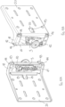
- an angular support device 1 adapted to hang a furnishing accessory of various types, and in particular a wall cabinet, to a wall.
- said angular support device 1 is adapted to be constrained to the inner surface of the side of a piece of furniture, at a rear edge portion thereof, and it is provided with hooking means which, when the device is mounted to the piece of furniture, face the wall, being adapted to cooperate with a special engagement element fixed to the wall at the height at which the piece of furniture is to be mounted, to keep the latter suspended.
- Said angular support device 1 comprises a mounting body 2 for attachment to the piece of furniture, which can be constrained to the inner surface of the side of a piece of furniture at a rear edge portion thereof, and supporting hooking means 3, adapted to cooperate with an engagement element (not shown), such as for example a bracket or a suitably shaped bar, fixed to the wall at a height at which the piece of furniture is to be mounted.
- an engagement element such as for example a bracket or a suitably shaped bar
- Said angular support body 2 advantageously consists of a support plate 10, adapted to support said hooking means 3, and a mounting plate 20, adapted to constrain said mounting body 2 to the piece of furniture, both preferably made of metal.
- the coupling between said support plate 10 and said mounting plate 20 is carried out by means of a sliding movement along a coupling direction, advantageously guided by guide means 40 provided on the latter. Furthermore, the coupling position between said support plate 10 and said mounting plate 20 is advantageously maintained through retaining means 44, which are rotatably movable preferably by means of plastic deformation between a neutral position and a retaining position.
- said angular support device 1 comprises an essentially rigid and two-dimensional support plate 10, preferably rectangular-shaped, wherein a through opening 11 is obtained, extending longitudinally in an area, preferably central with respect to the extension thereof, so as to allow the housing of hooking means 3.
- said hooking means 3 may for example be formed by a block 30, made of metal, and a hooking element 31 which typically has a circular or mushroom-shaped hooking head 31A, adapted to engage with a suitable seat obtained in the engagement element provided on the wall.
- said hooking means 3 comprise means for adjusting the hooking position of the piece of furniture: in particular, said hooking element 31 has a threaded shank 31B adapted to be engaged in a corresponding threaded hole obtained in the block 30, so as to pass through it according to a transversal, and preferably orthogonal direction.
- the end of the threaded shank 31B opposite the head 31A has a transverse seat 31C in which a special tool, such as a screwdriver, can be engaged so as to axially rotate the shank 31B and thus adjust the projection of the head 31A from the block 30 and thus improve the engagement with the wall engagement element in depth.
- a special tool such as a screwdriver
- said hooking means 3 preferably comprise a first grub screw 32 screwed onto a second threaded hole obtained in proximity of the upper edge of the block 30 and extending along an axis preferably inclined with respect to the latter, adapted to allow vertical adjustment of the hooking of the piece of furniture.
- the adjustment of said grub screws 32, 33 is carried out by acting with a special tool on a respective engagement seat 32B, 33B accessible through the opposite face of the block 30 with respect to the one where the respective heads 32A, 33A project.
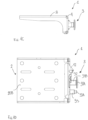
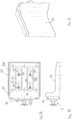
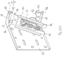
- said opening 11 has an outlet 11A at a lower edge, which allows the slidable insertion of the block 30 along the direction indicated by the arrow A illustrated in figures 2A and 2B .
- said support plate 10 further comprises a hood-shaped abutment element 12 projecting with respect to the surface of the support plate 10, preferably obtained at the upper margin of the opening 11; said abutment element 12 is adapted to cooperate with said first grub screw 32 to allow the adjustment of the vertical position of the block 30 with respect to the support plate 10.
- Two pairs of engagement fins 14 are advantageously obtained symmetrically projecting from said support plate 10, preferably at or in proximity of the vertices thereof, to facilitate the slidable coupling of said support plate 10 with said mounting plate 20, advantageously guided by guide means 40 as explained in greater detail below.
- Said essentially rigid, two-dimensional and preferably rectangular or square-shaped mounting plate 20 can be positioned with an outer face 20A on the inner surface of the side of the piece of furniture, advantageously at a rear edge portion, and anchorable therein for example by inserting special fixing means, such as for example screws, in a plurality of first through openings 21 advantageously obtained thereon.
- the mounting plate 20 in order to allow the mounting plate 20 to be mounted on the inner side of the piece of furniture, the latter may be provided with a plurality of coupling pins 21', projecting from said outer face 20A and adapted to be inserted into a corresponding plurality of holes suitably made in the side of the piece of furniture.
- Said mounting plate 20 is also advantageously provided with a plurality of second through openings 22, preferably slot-shaped and elongated preferably in the horizontal direction, adapted to allow the fixing of a covering element 50 once the angular support device 1 has been anchored to the piece of furniture as explained in greater detail below.
- said first guide fins 41 are not directly connected to the inner face 20B of the mounting plate 20 but they are continuously connected to a pair of edge portions 23 lying on planes orthogonal to the lying plane of the mounting plate 20 and extending at opposite lateral edges thereof, to form corner recesses.
- Said guide means 40 further comprise a pair of second guide fins 42 and a pair of third guide fins 43; in particular, in the embodiment shown in figures 2A and 2B , said second guide fins 42 and said third guide fins 43 are obtained projecting perpendicularly from the first guide fins 41, respectively laterally and at the end thereof, so as to form, together with the respective first guide fin 41, a track for the slidable insertion along a coupling direction B orthogonal to the mounting plate 20 of opposite edge portions of said support plate 10, whereon said pairs of engagement fins 14 are advantageously formed.
- said mounting plate 20 further comprises retaining means 44, for example formed by at least one tooth, and preferably a pair of teeth 44 projecting coplanar from said second guide fins 42, extending beyond the extension of the respective first guide fin 41, and they are movable between a neutral position, in which they allow the slidable coupling of said support plate 10 and said mounting plate 20, and a retaining position, in which they firmly maintain the achieved coupling position, preventing the two plates 10, 20 from slipping out.
- retaining means 44 for example formed by at least one tooth, and preferably a pair of teeth 44 projecting coplanar from said second guide fins 42, extending beyond the extension of the respective first guide fin 41, and they are movable between a neutral position, in which they allow the slidable coupling of said support plate 10 and said mounting plate 20, and a retaining position, in which they firmly maintain the achieved coupling position, preventing the two plates 10, 20 from slipping out.
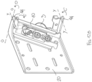
- said retaining teeth 44 are plastically folded by means of a rotation around an axis X-X, advantageously orthogonal to the coupling direction B and, in use, vertical, thus completing the assembly of the mounting body 2.
- the hooking means 3 are inserted into the through opening 11 obtained on the support plate 10 in order to proceed with the assembly of the angular support device 1, preferably carried out before fixing it to the side of the piece of furniture.
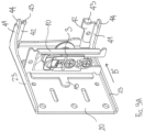
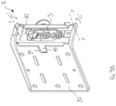
- Such operation may be advantageously carried out by translating said block 30, on which the hooking element 31 and the adjustment grub screws 32, 33 are screwed, along the direction indicated by the arrow A of figure 3A , so that the latter is positioned in the through opening 11, accessing thereinto through the outlet 11A and being guided by the lateral margins of the opening 11.
- the block 30 is then arranged in the opening 11 of the support plate 10 so that the head 32A of the first grub screw 32 abuts against the inner surface of the abutment element 12 obtained on the support plate 10, and that the hooking head 31A of the hooking element 31 projects in the same direction.
- the support plate 10 supporting the hooking means 3 is coupled to the mounting plate 20, so as to form the dihedral-shaped mounting body 2.
- Such coupling is advantageously carried out through a sliding movement of the support plate 10 along a coupling direction indicated by the arrow B in figure 3A , orthogonal to the inner face 20B of the mounting plate 20, said sliding being guided by said guide means 40.
- said retaining teeth 44 are advantageously folded plastically, as indicated by the arrows C of figure 3B , by means of a rotation around an axis X-X essentially orthogonal to the coupling direction B and vertical - in use - thus preventing a backward sliding movement which would entail decoupling of the two plates 10, 20.
- said coupling means 3 may also be of a different type with respect to what has been described above, provided that they are suitable for the purpose; for example, as shown in figures 4A - 4C , said hooking means 3 may comprise a hooking arm 31', provided at the upper end with a hooking element 31A' adapted to cooperate with the wall-fixed engagement element, and pivoted with the opposite end on said block 30.
- said hooking means 3 may also be provided with means 32', 33' for adjusting the position of the known and conventional type, for example formed by screw and nut mechanisms which allow to vary the position of the hooking arm 31' respectively depth and vertical-wise and therefore to adjust the hooking of the piece of furniture to the wall.
- said means for adjusting the depth position 32' may be advantageously formed by a first screw which is screwed into a seat provided for in said block 30 and whose head 32A' is engaged in a vertical slotted opening provided for on said hooking arm 31', so that rotations of said screw 32' allow to vary the inclination of the hooking arm 31' with respect to the block 30.
- Said means for adjusting the vertical position 33' may instead be formed by a second vertically arranged screw which is screwed into nut screw integrally joined with the hooking arm 31', so that rotations of said second screw 33' entail the vertical movement of the latter.
- the angular support device 1 when the angular support device 1 is associated with the piece of furniture, it is possible to affix the covering element 50 shown in figure 6 on the surface of the mounting body 2 facing toward the inner cavity of the piece of furniture.
- said covering element 50 has a shape essentially conjugated with that of the mounting body 2, and it can be fixed thereto by slidably inserting a plurality of coupling pins 51, obtained projecting from the inner face thereof, in the corresponding plurality of second slotted openings 22 provided for on the mounting plate 20 and described above.
- said covering element 50 is actually positioned on the mounting body 2, when the latter has already been assembled and anchored to the piece of furniture to be suspended, by inserting said coupling pins 51 into the corresponding slotted openings 22 obtained on said mounting plate 20, and in particular at an edge portion thereof which is distal from the support plate 10.
- the position of the covering element 50 with respect to the mounting body 2 can be adjusted easily by translating said coupling pins 51 to the corresponding slotted openings 22; as shown in figures 8A - 8C , the final position is advantageously reached when said covering element 50 abuts against the back of the piece of furniture to which the mounting body 2 is associated, irrespective of the thickness of the back itself and the distance of the latter from the suspension wall of the piece of furniture.
- Figures 9A and 9B show respective assembly steps of an angular support device according to a first variant embodiment of the present invention, in which the guide means 40 and the retaining means 44 are shaped in a manner such that the coupling between said support plate 10 and said mounting plate 20 occurs by means of a slidable movement of the latter along a coupling direction parallel to the plane defined by the mounting plate 20, and - in use - perpendicular to the wall for mounting the piece of furniture, indicated by arrow B' in figure 9A .
- the guide means 40 substantially comprise a pair of first advantageously parallel guide fins 41 which project perpendicularly with respect to the plane defined by the mounting plate 20, departing at corner portions of the inner face 20B.
- a pair of second guide fins 42 is also provided for projecting orthogonally from said first guide fins 41, preferably for the entire extension thereof.
- said first guide fins 41 are not directly connected to the inner face 20B of the mounting plate 20 but they are continuously connected to a pair of edge portions 23 lying on planes orthogonal to the lying plane of the mounting plate 20 and extending at opposite lateral edges thereof.
- said third guide fins 43 are obtained at the ends of said second guide fins 42, lying on a plane orthogonal thereto and parallel to the inner face 20B of the mounting plate 20.
- Said retaining teeth 44 extend coplanar with the ends of said first guide fins 41 and they are adapted to be plastically folded into the retaining position by means of a rotation C' around a rotation axis Y-Y essentially parallel to the coupling direction B', as indicated in figure 9B .
- the coupling between the support plate 10, supporting the hooking means 3, and the mounting plate 20 is therefore advantageously carried out through a slidable movement of the support plate 10 along the coupling direction B' guided by said guide means 40, and in particular by said third guide fins 43 assisted by the first guide fins 41.
- said support plate 10 is advantageously provided with an engagement element 15 adapted to be inserted, during assembly, into a corresponding cavity 25 provided on said mounting plate 20.
- the slidable coupling between the support plate 10 and the mounting plate 20 ends when the support plate 10 abuts against said second pair of guide fins 42, causing the ensuing formation of said edge 4.
- the retaining teeth 44 are advantageously folded plastically, as indicated by the arrows C', by means of a rotation around a rotation axis Y-Y essentially parallel to the coupling direction B', thus being arranged at the rear of the outermost pair of engagement fins 14 of the support plate 10, and said engagement element 15 is plastically folded into the cavity 25 to prevent the support plate 10 from accidentally de-coupling from the mounting plate 20 with a backward movement.
- Figure 11 shows a step for assembling an angular support device 1 according to an example not forming part of the invention.
- the coupling between the support plate 10 and the mounting plate 20 occurs by means of at least one rotation around a vertical axis V-V.
- the support plate 10 is approached to the mounting plate 20 so that a pair of engagement fins 14 provided for on the side of the latter arranged proximal to the mounting plate 20 is inserted into corresponding corner recesses.
- the support plate 10 is rotated around a vertical axis V-V passing essentially through the inner edge of the dihedron, as indicated by the arrow D, and said retaining teeth 44 are plastically folded, by means of a rotation C' around a rotation axis Y-Y parallel to the plane defined by the mounting plate 20, and - in use - perpendicular to the wall for mounting the piece of furniture.
- Figures 12A and 12B show a further example not forming part of the invention, in which the coupling between the support plate 10 and the mounting plate 20 occurs by means of at least one rotation around a horizontal axis O-O, as indicated by the arrow D', substantially defined by one of the first guide fins 41.
- a pair of engagement fins 14 provided for on said support plate 10 is advantageously obtained projecting vertically, to allow insertion in a corresponding pair of corner recesses provided for on the mounting plate 20.
- the coupling between said plates 10, 20 is completed by plastically folding the retention teeth 44 by means of a rotation C' around a rotation axis Y-Y parallel to the plane defined by the mounting plate 20, and - in use - perpendicular to the wall on which the piece of furniture is mounted.
- the process for producing an angular support device 1 therefore generally comprises the following steps:
- FIG. 13 shows the flat development of a mounting plate 20 according to the present invention.
- at least said mounting plate 20 can be advantageously obtained from a flat metal sheet, wherein some portions of sheet are folded, simultaneously or in subsequent steps, along appropriately provided weakening portions, to obtain the pairs of fins 41, 42 and 43 forming the guide means 40, and the retaining means 44.
- said support plate 10 can be obtained according to a similar production process, starting from a flat metal sheet.
- the mounting body 2 is made of two distinct and separate elements, which can be subsequently assembled by means of simple sliding or rotation movements.
- the coupling between said mounting plate 20 and said support plate 10 is advantageously guided by guide means suitably shaped according to the selected coupling movement and then stably maintained by retaining means movable from the neutral position to the retaining position in a simple and immediate manner.
- an angular support device is compact, i.e. having limited overall dimensions, but at the same time particularly stable and safe, adapted to bear even very high loads, a characteristic that makes it particularly suitable for fixing rather deep furniture, such as bases for kitchens or bathrooms, equipped with drawers, to the wall.
Landscapes
- Connection Of Plates (AREA)
- Furniture Connections (AREA)
- Supports Or Holders For Household Use (AREA)
- Cabinets, Racks, Or The Like Of Rigid Construction (AREA)
Claims (11)
- Winkelstützvorrichtung (1), angepasst zum Stützen eines Wandschranks an einer Wand, wobei die Vorrichtung (1) Folgendes umfasst:- Einhakmittel (3), angepasst zum Zusammenwirken mit wandbefestigten Eingriffsmitteln zum Stützen des Möbelstücks, und- einen zweiflächigen Montagekörper (2), umfassend eine Stützplatte (10), auf der die Einhakmittel (3) montiert werden können, und eine Montageplatte (20), umfassend ein Plattenelement zum Definieren einer Außenfläche (20A), die integral auf die Innenfläche der Seite eines Möbelstücks gespannt sein kann, wobei die Stützplatte (10) und die Montageplatte (20) im Gebrauch auf wechselseitig senkrechten Ebenen angeordnet sein können, um im Gebrauch ein starres Eckstück zu definieren, wobei die Stützplatte (10) und die Montageplatte (20) aus jeweils unterschiedlichen und getrennten Stücken bestehen, wobei die Montageplatte (20) ferner Führungsmittel (40) umfasst, um das gleitende Koppeln mit der Stützplatte (10) entlang einer Kopplungsrichtung (B, B') während des Verbindens zu ermöglichen, wobei die Führungsmittel (40) umfassen:- ein Paar von ersten Führungsrippen (41), die senkrecht an Eckabschnitten einer Innenfläche (20B) des Plattenelements der Montageplatte (20) gegenüber der Außenfläche (20A) vorstehen,- ein Paar von zweiten Führungsrippen (42), die senkrecht von den ersten Führungsrippen (41) vorstehen, und- ein Paar von dritten Führungsrippen (43), die entweder senkrecht von den Enden der ersten Führungsrippen (41) vorstehen, um zusammen mit den jeweiligen ersten und zweiten Führungsrippen (41, 42) eine Spur zum gleitenden Einsetzen der Stützplatte (10) entlang einer ersten Kopplungsrichtung (B) orthogonal zum Plattenelement der Montageplatte (20) zu bilden, oderdie senkrecht von den Enden der zweiten Führungsrippen (42) vorstehen, in einer Ebene parallel zum Plattenelement der Montageplatte (20) liegend, um mit der jeweiligen ersten Führungsrippe (41) eine Führung zum gleitenden Einsetzen der Stützplatte (10) entlang einer zweiten Kopplungsrichtung (B') parallel zum Plattenelement der Montageplatte (20) zu bilden,wobei die Montageplatte (20) ferner Haltemittel (44) umfasst, die von einer neutralen Position zu einer Halteposition während des Verbindens zum Erhalten der Verbindung des Montagekörpers (2) bewegt werden, eine Rückwärtsgleitbewegung der Stützplatte (10) verhindernd.
- Winkelstützvorrichtung (1) nach Anspruch 1, wobei die Haltemittel (44) von wenigstens einem Haltezahn gebildet werden, dessen Übergang von der neutralen Position zur Halteposition durch plastische Verformung mit einer Drehung (C, C) um eine Drehachse (X-X, Y-Y) erfolgt.
- Winkelstützvorrichtung (1) nach Anspruch 2, wobei der wenigstens eine Haltezahn (44) zum Vorstehen auf eine koplanare Weise von einer entsprechenden zweiten Führungsrippe (42) vorgesehen ist, über die Erstreckung der jeweiligen ersten Führungsrippe (41) hinaus entwickelnd, wobei die Drehachse (X-X) orthogonal zur ersten Kopplungsrichtung (B) und im Gebrauch vertikal ist.
- Winkelstützvorrichtung (1) nach Anspruch 2, wobei der wenigstens eine Haltezahn (44) zum Vorstehen auf eine koplanare Weise vom Ende von einer des Paars von ersten Führungsrippen (41) vorgesehen ist, wobei die Drehachse (Y-Y) parallel zur zweiten Kopplungsrichtung (B') ist.
- Winkelstützvorrichtung (1) nach Anspruch 4, wobei die Stützplatte (10) ferner ein Eingriffselement (15), angepasst zum Eingesetztwerden in einen entsprechenden Hohlraum (25), der auf der Montageplatte (20) erhalten wird, um ein Entkoppeln zu verhindern, umfasst.
- Winkelstützvorrichtung (1) nach einem der vorhergehenden Ansprüche, wobei die Einhakmittel (3) in einer auf der Montageplatte (10) erhaltenen Öffnung (11) angeordnet werden können.
- Winkelstützvorrichtung (1) nach Anspruch 6, wobei die Einhakmittel (3) gleitend in die Öffnung (11) durch einen an einem unteren Rand der Stützplatte (10) erhaltenen Ausgang (11 A) eingesetzt werden.
- Winkelstützvorrichtung (1) nach einem der vorhergehenden Ansprüche, wobei die Einhakmittel (3) ein Einhakelement (31 A, 31 A') und Mittel zum Anpassen der Einhakpositionstiefe und in vertikaler Weise umfassen.
- Winkelstützvorrichtung (1) nach einem der vorhergehenden Ansprüche, ferner umfassend ein Abdeckelement (50), angepasst zum Verbundenwerden mit dem Montagekörper (2), wenn letzterer auf dem Möbelstück montiert ist, wobei das Abdeckelement (50) mit einer Vielzahl von Kopplungsstiften (51), angepasst zum gleitenden Eingriff in eine entsprechende Vielzahl von geschlitzten Öffnungen (22), erhalten auf der Montageplatte (20), ausgestattet ist.
- Möbelstück, umfassend eine Winkelstützvorrichtung (1) nach einem der Ansprüche 1 bis 9,
- Verfahren zum Herstellen einer Winkelstützvorrichtung (1) nach Anspruch 1, umfassend die folgenden Schritte:a) Verbinden des Einhakmittels (3) mit der Stützplatte (10);b) Koppeln der Stützplatte (10) mit der Montageplatte (20) mit Hilfe der Führungsmittel (40), um den Montagekörper (2) zu erhalten;c) Bewegen des Rückhaltemittels (44) aus einer neutralen Position in eine Halteposition, um die Verbindung des Montagekörpers (2) stabil zu halten.
Priority Applications (1)
| Application Number | Priority Date | Filing Date | Title |
|---|---|---|---|
| EP24214163.8A EP4487732B1 (de) | 2019-12-03 | 2020-11-23 | Herstellungsverfahren einer winkelstützvorrichtung für wandschränke |
Applications Claiming Priority (2)
| Application Number | Priority Date | Filing Date | Title |
|---|---|---|---|
| IT102019000022788A IT201900022788A1 (it) | 2019-12-03 | 2019-12-03 | Dispositivo di supporto angolare per mobili pensili |
| PCT/IB2020/061024 WO2021111241A1 (en) | 2019-12-03 | 2020-11-23 | Angular support device for wall cabinets |
Related Child Applications (2)
| Application Number | Title | Priority Date | Filing Date |
|---|---|---|---|
| EP24214163.8A Division EP4487732B1 (de) | 2019-12-03 | 2020-11-23 | Herstellungsverfahren einer winkelstützvorrichtung für wandschränke |
| EP24214163.8A Division-Into EP4487732B1 (de) | 2019-12-03 | 2020-11-23 | Herstellungsverfahren einer winkelstützvorrichtung für wandschränke |
Publications (2)
| Publication Number | Publication Date |
|---|---|
| EP4069037A1 EP4069037A1 (de) | 2022-10-12 |
| EP4069037B1 true EP4069037B1 (de) | 2025-01-15 |
Family
ID=70009202
Family Applications (2)
| Application Number | Title | Priority Date | Filing Date |
|---|---|---|---|
| EP24214163.8A Active EP4487732B1 (de) | 2019-12-03 | 2020-11-23 | Herstellungsverfahren einer winkelstützvorrichtung für wandschränke |
| EP20825238.7A Active EP4069037B1 (de) | 2019-12-03 | 2020-11-23 | Winkelhalterung für wandschränke |
Family Applications Before (1)
| Application Number | Title | Priority Date | Filing Date |
|---|---|---|---|
| EP24214163.8A Active EP4487732B1 (de) | 2019-12-03 | 2020-11-23 | Herstellungsverfahren einer winkelstützvorrichtung für wandschränke |
Country Status (6)
| Country | Link |
|---|---|
| EP (2) | EP4487732B1 (de) |
| CN (1) | CN114650752B (de) |
| BR (1) | BR112022008132A2 (de) |
| ES (1) | ES3009346T3 (de) |
| IT (1) | IT201900022788A1 (de) |
| WO (1) | WO2021111241A1 (de) |
Families Citing this family (1)
| Publication number | Priority date | Publication date | Assignee | Title |
|---|---|---|---|---|
| IT201800005913A1 (it) * | 2018-05-31 | 2019-12-01 | Maniglia di sicurezza per il controllo di accessi di macchine o impianti industriali |
Family Cites Families (7)
| Publication number | Priority date | Publication date | Assignee | Title |
|---|---|---|---|---|
| AT384354B (de) * | 1981-06-05 | 1987-11-10 | Blum Gmbh Julius | Aufhaengebeschlag, insbesondere fuer haengeschraenke |
| EP0389054B1 (de) * | 1989-03-20 | 1995-07-05 | CAMAR S.p.A. | Verborgene Vorrichtung zur Wandmontage eines Wandmöbelelementes |
| ITMI20070789A1 (it) | 2007-04-18 | 2008-10-19 | Leonardo Srl | Gruppo reggipensile nascosto e regolabile per il montaggio a parete di un mobile pensile |
| DE202008015700U1 (de) * | 2008-11-27 | 2010-04-15 | Hettich-Heinze Gmbh & Co. Kg | Winkelbeschlag |
| EP3289925B1 (de) | 2008-11-27 | 2021-04-07 | Hettich-Heinze GmbH & Co. KG | Winkelbeschlag |
| IT1393831B1 (it) * | 2009-04-24 | 2012-05-11 | Leonardo Srl | Sistema di antisganciamento per mobili pensili |
| EP3157386B1 (de) * | 2014-06-23 | 2018-04-11 | Leonardo S.r.L. | Verborgenes verbessertes aushänggesicherungssystem für wandkasten |
-
2019
- 2019-12-03 IT IT102019000022788A patent/IT201900022788A1/it unknown
-
2020
- 2020-11-23 BR BR112022008132A patent/BR112022008132A2/pt not_active Application Discontinuation
- 2020-11-23 ES ES20825238T patent/ES3009346T3/es active Active
- 2020-11-23 WO PCT/IB2020/061024 patent/WO2021111241A1/en not_active Ceased
- 2020-11-23 CN CN202080077595.4A patent/CN114650752B/zh active Active
- 2020-11-23 EP EP24214163.8A patent/EP4487732B1/de active Active
- 2020-11-23 EP EP20825238.7A patent/EP4069037B1/de active Active
Also Published As
| Publication number | Publication date |
|---|---|
| WO2021111241A1 (en) | 2021-06-10 |
| EP4487732A2 (de) | 2025-01-08 |
| EP4487732B1 (de) | 2026-04-22 |
| CN114650752B (zh) | 2025-03-04 |
| EP4069037A1 (de) | 2022-10-12 |
| IT201900022788A1 (it) | 2021-06-03 |
| EP4487732A3 (de) | 2025-04-02 |
| ES3009346T3 (en) | 2025-03-26 |
| CN114650752A (zh) | 2022-06-21 |
| BR112022008132A2 (pt) | 2022-07-19 |
Similar Documents
| Publication | Publication Date | Title |
|---|---|---|
| US12185833B2 (en) | Wall-mounted, configurable storage system | |
| EP2867420B1 (de) | Umrandungsleistenklemme für rasterdeckenläufer | |
| US11375812B2 (en) | Wall-mounted, configurable storage system | |
| WO2014160410A1 (en) | Support bracket | |
| EP4069037B1 (de) | Winkelhalterung für wandschränke | |
| EP2886012B1 (de) | Befestigungssytem für möbel | |
| US2727711A (en) | Adjustable shelf support | |
| EP4103016A1 (de) | Befestigungselement für ein regal | |
| JP2004537019A (ja) | 形材要素を連結するための装置、締め付け要素および係止要素 | |
| US6354759B1 (en) | Connector for frame members | |
| CN111065787A (zh) | 地震监测仪夹头 | |
| US8309849B2 (en) | Attachable supporting spacer for electrical boxes | |
| US10925787B2 (en) | Adjustable lift chair frame | |
| CN113226119B (zh) | 具有锁定系统的搁架和用于将搁架锁定至家具用品的方法 | |
| EP4358794B1 (de) | Stützvorrichtung für möbel | |
| RU2801930C2 (ru) | Выдвижной ящик с противоподъемной системой | |
| JP7770172B2 (ja) | 不陸調整構造 | |
| JPS5826595Y2 (ja) | 棚板の保持装置 | |
| JP2507965Y2 (ja) | 物品支持部材の支持構造 | |
| JPH0119902Y2 (de) | ||
| WO2018090076A1 (en) | Adjustable mounting system for attaching and aligning drawer fronts | |
| JPH0732680Y2 (ja) | フレーム材の連結構造 | |
| JP3774866B2 (ja) | 間仕切り装置のパネル支持構造 | |
| JP2022045595A (ja) | 棚板保持部材 | |
| JPH0450788Y2 (de) |
Legal Events
| Date | Code | Title | Description |
|---|---|---|---|
| STAA | Information on the status of an ep patent application or granted ep patent |
Free format text: STATUS: UNKNOWN |
|
| STAA | Information on the status of an ep patent application or granted ep patent |
Free format text: STATUS: THE INTERNATIONAL PUBLICATION HAS BEEN MADE |
|
| PUAI | Public reference made under article 153(3) epc to a published international application that has entered the european phase |
Free format text: ORIGINAL CODE: 0009012 |
|
| STAA | Information on the status of an ep patent application or granted ep patent |
Free format text: STATUS: REQUEST FOR EXAMINATION WAS MADE |
|
| 17P | Request for examination filed |
Effective date: 20220329 |
|
| AK | Designated contracting states |
Kind code of ref document: A1 Designated state(s): AL AT BE BG CH CY CZ DE DK EE ES FI FR GB GR HR HU IE IS IT LI LT LU LV MC MK MT NL NO PL PT RO RS SE SI SK SM TR |
|
| DAV | Request for validation of the european patent (deleted) | ||
| DAX | Request for extension of the european patent (deleted) | ||
| P01 | Opt-out of the competence of the unified patent court (upc) registered |
Effective date: 20230329 |
|
| STAA | Information on the status of an ep patent application or granted ep patent |
Free format text: STATUS: EXAMINATION IS IN PROGRESS |
|
| 17Q | First examination report despatched |
Effective date: 20230824 |
|
| GRAP | Despatch of communication of intention to grant a patent |
Free format text: ORIGINAL CODE: EPIDOSNIGR1 |
|
| STAA | Information on the status of an ep patent application or granted ep patent |
Free format text: STATUS: GRANT OF PATENT IS INTENDED |
|
| INTG | Intention to grant announced |
Effective date: 20240906 |
|
| GRAS | Grant fee paid |
Free format text: ORIGINAL CODE: EPIDOSNIGR3 |
|
| GRAA | (expected) grant |
Free format text: ORIGINAL CODE: 0009210 |
|
| STAA | Information on the status of an ep patent application or granted ep patent |
Free format text: STATUS: THE PATENT HAS BEEN GRANTED |
|
| AK | Designated contracting states |
Kind code of ref document: B1 Designated state(s): AL AT BE BG CH CY CZ DE DK EE ES FI FR GB GR HR HU IE IS IT LI LT LU LV MC MK MT NL NO PL PT RO RS SE SI SK SM TR |
|
| REG | Reference to a national code |
Ref country code: CH Ref legal event code: EP Ref country code: GB Ref legal event code: FG4D |
|
| REG | Reference to a national code |
Ref country code: DE Ref legal event code: R096 Ref document number: 602020044924 Country of ref document: DE |
|
| REG | Reference to a national code |
Ref country code: IE Ref legal event code: FG4D |
|
| REG | Reference to a national code |
Ref country code: NL Ref legal event code: FP |
|
| REG | Reference to a national code |
Ref country code: ES Ref legal event code: FG2A Ref document number: 3009346 Country of ref document: ES Kind code of ref document: T3 Effective date: 20250326 |
|
| PG25 | Lapsed in a contracting state [announced via postgrant information from national office to epo] |
Ref country code: RS Free format text: LAPSE BECAUSE OF FAILURE TO SUBMIT A TRANSLATION OF THE DESCRIPTION OR TO PAY THE FEE WITHIN THE PRESCRIBED TIME-LIMIT Effective date: 20250415 |
|
| PG25 | Lapsed in a contracting state [announced via postgrant information from national office to epo] |
Ref country code: FI Free format text: LAPSE BECAUSE OF FAILURE TO SUBMIT A TRANSLATION OF THE DESCRIPTION OR TO PAY THE FEE WITHIN THE PRESCRIBED TIME-LIMIT Effective date: 20250115 |
|
| PG25 | Lapsed in a contracting state [announced via postgrant information from national office to epo] |
Ref country code: PL Free format text: LAPSE BECAUSE OF FAILURE TO SUBMIT A TRANSLATION OF THE DESCRIPTION OR TO PAY THE FEE WITHIN THE PRESCRIBED TIME-LIMIT Effective date: 20250115 |
|
| REG | Reference to a national code |
Ref country code: LT Ref legal event code: MG9D |
|
| PG25 | Lapsed in a contracting state [announced via postgrant information from national office to epo] |
Ref country code: NO Free format text: LAPSE BECAUSE OF FAILURE TO SUBMIT A TRANSLATION OF THE DESCRIPTION OR TO PAY THE FEE WITHIN THE PRESCRIBED TIME-LIMIT Effective date: 20250415 Ref country code: IS Free format text: LAPSE BECAUSE OF FAILURE TO SUBMIT A TRANSLATION OF THE DESCRIPTION OR TO PAY THE FEE WITHIN THE PRESCRIBED TIME-LIMIT Effective date: 20250515 |
|
| PG25 | Lapsed in a contracting state [announced via postgrant information from national office to epo] |
Ref country code: HR Free format text: LAPSE BECAUSE OF FAILURE TO SUBMIT A TRANSLATION OF THE DESCRIPTION OR TO PAY THE FEE WITHIN THE PRESCRIBED TIME-LIMIT Effective date: 20250115 |
|
| PG25 | Lapsed in a contracting state [announced via postgrant information from national office to epo] |
Ref country code: LV Free format text: LAPSE BECAUSE OF FAILURE TO SUBMIT A TRANSLATION OF THE DESCRIPTION OR TO PAY THE FEE WITHIN THE PRESCRIBED TIME-LIMIT Effective date: 20250115 Ref country code: PT Free format text: LAPSE BECAUSE OF FAILURE TO SUBMIT A TRANSLATION OF THE DESCRIPTION OR TO PAY THE FEE WITHIN THE PRESCRIBED TIME-LIMIT Effective date: 20250515 |
|
| PG25 | Lapsed in a contracting state [announced via postgrant information from national office to epo] |
Ref country code: GR Free format text: LAPSE BECAUSE OF FAILURE TO SUBMIT A TRANSLATION OF THE DESCRIPTION OR TO PAY THE FEE WITHIN THE PRESCRIBED TIME-LIMIT Effective date: 20250416 Ref country code: BG Free format text: LAPSE BECAUSE OF FAILURE TO SUBMIT A TRANSLATION OF THE DESCRIPTION OR TO PAY THE FEE WITHIN THE PRESCRIBED TIME-LIMIT Effective date: 20250115 |
|
| PG25 | Lapsed in a contracting state [announced via postgrant information from national office to epo] |
Ref country code: SE Free format text: LAPSE BECAUSE OF FAILURE TO SUBMIT A TRANSLATION OF THE DESCRIPTION OR TO PAY THE FEE WITHIN THE PRESCRIBED TIME-LIMIT Effective date: 20250115 |
|
| PG25 | Lapsed in a contracting state [announced via postgrant information from national office to epo] |
Ref country code: SM Free format text: LAPSE BECAUSE OF FAILURE TO SUBMIT A TRANSLATION OF THE DESCRIPTION OR TO PAY THE FEE WITHIN THE PRESCRIBED TIME-LIMIT Effective date: 20250115 |
|
| PG25 | Lapsed in a contracting state [announced via postgrant information from national office to epo] |
Ref country code: DK Free format text: LAPSE BECAUSE OF FAILURE TO SUBMIT A TRANSLATION OF THE DESCRIPTION OR TO PAY THE FEE WITHIN THE PRESCRIBED TIME-LIMIT Effective date: 20250115 |
|
| PG25 | Lapsed in a contracting state [announced via postgrant information from national office to epo] |
Ref country code: IT Free format text: LAPSE BECAUSE OF FAILURE TO SUBMIT A TRANSLATION OF THE DESCRIPTION OR TO PAY THE FEE WITHIN THE PRESCRIBED TIME-LIMIT Effective date: 20250115 |
|
| REG | Reference to a national code |
Ref country code: DE Ref legal event code: R097 Ref document number: 602020044924 Country of ref document: DE |
|
| PG25 | Lapsed in a contracting state [announced via postgrant information from national office to epo] |
Ref country code: CZ Free format text: LAPSE BECAUSE OF FAILURE TO SUBMIT A TRANSLATION OF THE DESCRIPTION OR TO PAY THE FEE WITHIN THE PRESCRIBED TIME-LIMIT Effective date: 20250115 Ref country code: EE Free format text: LAPSE BECAUSE OF FAILURE TO SUBMIT A TRANSLATION OF THE DESCRIPTION OR TO PAY THE FEE WITHIN THE PRESCRIBED TIME-LIMIT Effective date: 20250115 |
|
| PG25 | Lapsed in a contracting state [announced via postgrant information from national office to epo] |
Ref country code: RO Free format text: LAPSE BECAUSE OF FAILURE TO SUBMIT A TRANSLATION OF THE DESCRIPTION OR TO PAY THE FEE WITHIN THE PRESCRIBED TIME-LIMIT Effective date: 20250115 |
|
| PG25 | Lapsed in a contracting state [announced via postgrant information from national office to epo] |
Ref country code: SK Free format text: LAPSE BECAUSE OF FAILURE TO SUBMIT A TRANSLATION OF THE DESCRIPTION OR TO PAY THE FEE WITHIN THE PRESCRIBED TIME-LIMIT Effective date: 20250115 |
|
| PLBE | No opposition filed within time limit |
Free format text: ORIGINAL CODE: 0009261 |
|
| STAA | Information on the status of an ep patent application or granted ep patent |
Free format text: STATUS: NO OPPOSITION FILED WITHIN TIME LIMIT |
|
| PGFP | Annual fee paid to national office [announced via postgrant information from national office to epo] |
Ref country code: NL Payment date: 20251119 Year of fee payment: 6 |
|
| 26N | No opposition filed |
Effective date: 20251016 |
|
| PGFP | Annual fee paid to national office [announced via postgrant information from national office to epo] |
Ref country code: DE Payment date: 20251119 Year of fee payment: 6 |
|
| PGFP | Annual fee paid to national office [announced via postgrant information from national office to epo] |
Ref country code: AT Payment date: 20251120 Year of fee payment: 6 |
|
| PGFP | Annual fee paid to national office [announced via postgrant information from national office to epo] |
Ref country code: ES Payment date: 20251229 Year of fee payment: 6 |