EP4067947B1 - Optical unit, beam coupling device, and laser processing machine - Google Patents
Optical unit, beam coupling device, and laser processing machine Download PDFInfo
- Publication number
- EP4067947B1 EP4067947B1 EP20894129.4A EP20894129A EP4067947B1 EP 4067947 B1 EP4067947 B1 EP 4067947B1 EP 20894129 A EP20894129 A EP 20894129A EP 4067947 B1 EP4067947 B1 EP 4067947B1
- Authority
- EP
- European Patent Office
- Prior art keywords
- light
- optical unit
- coupling device
- face
- optical
- Prior art date
- Legal status (The legal status is an assumption and is not a legal conclusion. Google has not performed a legal analysis and makes no representation as to the accuracy of the status listed.)
- Active
Links
Images




Classifications
-
- G—PHYSICS
- G02—OPTICS
- G02B—OPTICAL ELEMENTS, SYSTEMS OR APPARATUS
- G02B27/00—Optical systems or apparatus not provided for by any of the groups G02B1/00 - G02B26/00, G02B30/00
- G02B27/10—Beam splitting or combining systems
- G02B27/1006—Beam splitting or combining systems for splitting or combining different wavelengths
-
- B—PERFORMING OPERATIONS; TRANSPORTING
- B23—MACHINE TOOLS; METAL-WORKING NOT OTHERWISE PROVIDED FOR
- B23K—SOLDERING OR UNSOLDERING; WELDING; CLADDING OR PLATING BY SOLDERING OR WELDING; CUTTING BY APPLYING HEAT LOCALLY, e.g. FLAME CUTTING; WORKING BY LASER BEAM
- B23K26/00—Working by laser beam, e.g. welding, cutting or boring
- B23K26/02—Positioning or observing the workpiece, e.g. with respect to the point of impact; Aligning, aiming or focusing the laser beam
- B23K26/06—Shaping the laser beam, e.g. by masks or multi-focusing
- B23K26/064—Shaping the laser beam, e.g. by masks or multi-focusing by means of optical elements, e.g. lenses, mirrors or prisms
-
- G—PHYSICS
- G02—OPTICS
- G02B—OPTICAL ELEMENTS, SYSTEMS OR APPARATUS
- G02B27/00—Optical systems or apparatus not provided for by any of the groups G02B1/00 - G02B26/00, G02B30/00
- G02B27/09—Beam shaping, e.g. changing the cross-sectional area, not otherwise provided for
- G02B27/0938—Using specific optical elements
- G02B27/0944—Diffractive optical elements, e.g. gratings, holograms
-
- G—PHYSICS
- G02—OPTICS
- G02B—OPTICAL ELEMENTS, SYSTEMS OR APPARATUS
- G02B27/00—Optical systems or apparatus not provided for by any of the groups G02B1/00 - G02B26/00, G02B30/00
- G02B27/09—Beam shaping, e.g. changing the cross-sectional area, not otherwise provided for
- G02B27/0938—Using specific optical elements
- G02B27/095—Refractive optical elements
- G02B27/0955—Lenses
-
- G—PHYSICS
- G02—OPTICS
- G02B—OPTICAL ELEMENTS, SYSTEMS OR APPARATUS
- G02B27/00—Optical systems or apparatus not provided for by any of the groups G02B1/00 - G02B26/00, G02B30/00
- G02B27/10—Beam splitting or combining systems
- G02B27/1086—Beam splitting or combining systems operating by diffraction only
-
- G—PHYSICS
- G02—OPTICS
- G02B—OPTICAL ELEMENTS, SYSTEMS OR APPARATUS
- G02B27/00—Optical systems or apparatus not provided for by any of the groups G02B1/00 - G02B26/00, G02B30/00
- G02B27/10—Beam splitting or combining systems
- G02B27/12—Beam splitting or combining systems operating by refraction only
- G02B27/123—The splitting element being a lens or a system of lenses, including arrays and surfaces with refractive power
-
- G—PHYSICS
- G02—OPTICS
- G02B—OPTICAL ELEMENTS, SYSTEMS OR APPARATUS
- G02B3/00—Simple or compound lenses
-
- G—PHYSICS
- G02—OPTICS
- G02B—OPTICAL ELEMENTS, SYSTEMS OR APPARATUS
- G02B5/00—Optical elements other than lenses
- G02B5/18—Diffraction gratings
-
- H—ELECTRICITY
- H01—ELECTRIC ELEMENTS
- H01S—DEVICES USING THE PROCESS OF LIGHT AMPLIFICATION BY STIMULATED EMISSION OF RADIATION [LASER] TO AMPLIFY OR GENERATE LIGHT; DEVICES USING STIMULATED EMISSION OF ELECTROMAGNETIC RADIATION IN WAVE RANGES OTHER THAN OPTICAL
- H01S5/00—Semiconductor lasers
- H01S5/10—Construction or shape of the optical resonator, e.g. extended or external cavity, coupled cavities, bent-guide, varying width, thickness or composition of the active region
- H01S5/14—External cavity lasers
- H01S5/141—External cavity lasers using a wavelength selective device, e.g. a grating or etalon
-
- H—ELECTRICITY
- H01—ELECTRIC ELEMENTS
- H01S—DEVICES USING THE PROCESS OF LIGHT AMPLIFICATION BY STIMULATED EMISSION OF RADIATION [LASER] TO AMPLIFY OR GENERATE LIGHT; DEVICES USING STIMULATED EMISSION OF ELECTROMAGNETIC RADIATION IN WAVE RANGES OTHER THAN OPTICAL
- H01S5/00—Semiconductor lasers
- H01S5/40—Arrangement of two or more semiconductor lasers, not provided for in groups H01S5/02 - H01S5/30
- H01S5/4012—Beam combining, e.g. by the use of fibres, gratings, polarisers, prisms
-
- H—ELECTRICITY
- H01—ELECTRIC ELEMENTS
- H01S—DEVICES USING THE PROCESS OF LIGHT AMPLIFICATION BY STIMULATED EMISSION OF RADIATION [LASER] TO AMPLIFY OR GENERATE LIGHT; DEVICES USING STIMULATED EMISSION OF ELECTROMAGNETIC RADIATION IN WAVE RANGES OTHER THAN OPTICAL
- H01S5/00—Semiconductor lasers
- H01S5/40—Arrangement of two or more semiconductor lasers, not provided for in groups H01S5/02 - H01S5/30
- H01S5/4025—Array arrangements, e.g. constituted by discrete laser diodes or laser bar
- H01S5/4031—Edge-emitting structures
- H01S5/4062—Edge-emitting structures with an external cavity or using internal filters, e.g. Talbot filters
-
- H—ELECTRICITY
- H01—ELECTRIC ELEMENTS
- H01S—DEVICES USING THE PROCESS OF LIGHT AMPLIFICATION BY STIMULATED EMISSION OF RADIATION [LASER] TO AMPLIFY OR GENERATE LIGHT; DEVICES USING STIMULATED EMISSION OF ELECTROMAGNETIC RADIATION IN WAVE RANGES OTHER THAN OPTICAL
- H01S5/00—Semiconductor lasers
- H01S5/40—Arrangement of two or more semiconductor lasers, not provided for in groups H01S5/02 - H01S5/30
- H01S5/4025—Array arrangements, e.g. constituted by discrete laser diodes or laser bar
- H01S5/4087—Array arrangements, e.g. constituted by discrete laser diodes or laser bar emitting more than one wavelength
Definitions
- the present disclosure relates to an optical unit, a beam coupling device including the optical unit, and a laser processing machine including the beam coupling device.
- US 2016/0048028 A1 discloses a wavelength beam combining laser system in which individual light beams are superposed to form a coupling beam.
- US 2016/0048028 A1 also discloses that light beams from a plurality of diode bars are condensed on an optical fiber from the viewpoint of increasing light outputs. Further, for the purpose of reducing the size of the laser system, an optical system for removing arrangement of a coupling lens in wavelength beam combining from a focal length is separately included, and a beam rotor is rotated.
- WO 2018/163598 A1 shows a wavelength combining laser apparatus including a semiconductor laser to emit a plurality of laser beams and a wavelength combining element to combine the plurality of laser beams into a single laser beam.
- the wavelength combining laser apparatus of WO 2018/163598 A1 also includes a cross-coupling reduction optical system having a positive power in a laser beam combining direction perpendicular to an optical axis of the single laser beam that is output from the wavelength combining element; and a partially-reflective mirror to reflect the single laser beam that passes through the cross-coupling reduction optical system and to allow the single laser beam to transmit through and exit the partially-reflective mirror.
- US 2020/379248 A1 discloses an optical resonator including a light source and an output coupler.
- the light source emits light.
- the output coupler resonates the light emitted from the light source to emit output light.
- the output coupler includes a mirror, a polarization beam splitter, at least one quarter-wave plate, and an adjuster.
- WO 2009/137703 A2 shows optical systems and components thereof which may be used for maintaining the brightness of laser emitter bar output beams.
- EP 3506437 A1 discloses a laser module comprising a laser diode including a plurality of emitters arrayed along a first line, and emitting a laser beam from each one of the plurality of emitters at an emitting surface; a first collimator lens disposed facing the emitting surface of the laser diode, and having positive power along a fast axis; a beam twister disposed facing the laser beam given off from the first collimator lens, and turning the laser beam by approx. 90 degrees; and an optical element disposed facing the laser beam given off from the beam twister, and including a plurality of incident surfaces placed in a stepped shape.
- the present disclosure provides an optical unit capable of improving a degree of freedom in design for guiding a plurality of light beams, a beam coupling device, and a laser processing machine.
- optical unit according to the present disclosure is provided as defined in claim 1.
- the beam coupling device according to one aspect of the present invention is defined in claim 4.
- the beam coupling device according to another aspect of the present invention is defined in claim 6.
- the laser processing machine according to the present invention is defined in claim 8.
- the optical unit, the beam coupling device, and the laser processing machine according to the present disclosure it is possible to improve the degree of freedom in design for guiding a plurality of light beams.
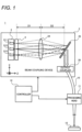
- FIG. 1 is a diagram illustrating a configuration of a laser processing machine 1 according to the present embodiment.
- FIG. 1 is a diagram illustrating a configuration of a laser processing machine 1 according to the present embodiment.
- the laser processing machine 1 includes a beam coupling device 2, a transmission optical system 10, a processing head 11, and a controller 12.
- the laser processing machine 1 is a device that irradiates various workpieces 15 with laser light to perform various laser processing.
- the various laser processing include, laser welding, laser cutting, and laser perforation.
- the beam coupling device 2 is a device that couples a plurality of light beams emitted separately, in order to supply the laser light of the laser processing machine 1, for example.
- the beam coupling device 2 is configured by adopting wavelength beam combining in which a plurality of light beams are combined with resonating at different wavelengths.
- the beam coupling device 2 for wavelength beam combining can facilitate to obtain high beam quality and to narrow down the beam diameter.
- the transmission optical system 10 is an optical system that transmits the laser light from the beam coupling device 2 to the processing head 11, including an optical fiber, for example.
- the processing head 11 is a device that is arranged to face the workpiece 15 to irradiate the workpiece 15 with a laser light transmitted from the beam coupling device 2, for example.
- the controller 12 is a control device that controls the overall operation of the laser processing machine 1.
- the controller 12 includes, for example, a CPU or MPU that cooperates with software to realize a predetermined function.
- the controller 12 may be provided with an internal memory for storing various programs and data, and various interfaces capable of inputting oscillation conditions and the like by the operation of the user.
- the controller 12 may include a hardware circuit such as ASIC or FPGA that realize various functions. Further, the controller 12 may be integrally configured with the drive circuit of the light source.
- the beam coupling device 2 of the present embodiment includes an LD bar 3 which is an example of a light source, an optical unit 4, a coupling lens 24, a diffraction element 25, and an output coupler 26, for example.
- the beam coupling device 2 of the present embodiment constitutes an external resonance type optical resonator that resonates light in an optical path that reciprocates between the LD bar 3 and the output coupler 26.
- the LD bar 3 is formed of an array of light emitters including a plurality of LDs (laser diodes) 311 to 315 arranged one-dimensionally.
- a direction in which the LDs 311 to 315 are arranged is referred to as "X direction”
- a direction of the optical axis of the light beam emitted by the LD bar 3 from the LDs 311 to 315 is referred to as "Z direction”
- Y direction orthogonal to the X and Z directions is referred to as "Y direction”.
- FIG. 1 illustrates three LD 311, 313, and 315 in the LD bar 3.
- the number of LDs 311 to 315 included in the LD bar 3 is e.g. tens to hundreds.
- the plurality of LDs 311 to 315 have a common spontaneous emission spectrum depending on the material of the LD light emitting layer, for example (refer to FIG. 3 ).
- the generic term of LDs 311 to 315 may be referred to as "LD 31".
- Each LD 31 is an example of a light emitter constituting the emitter of the LD bar 3, to emit a light beam toward the +Z side, respectively.
- the optical unit 4 is an optical system that adjusts and guides a plurality of light beams from each LD 31 of the LD bar 3.
- the optical unit 4 is arranged on the +Z side of the LD bar 3. According to the optical unit 4 of the present embodiment, the degree of freedom in design can be improved for the beam coupling device 2 for wavelength beam combining, which is likely to have a complicated optical design, and the size of the beam coupling device 2 can be redueced. The details of the optical unit 4 will be described later.
- the coupling lens 24 is arranged on the +Z side of the optical unit 4 with a distance D1, for example.
- the distance D1 on the -Z side of the coupling lens 24 is set to the focal length of the coupling lens 24, for example.
- the plurality of light beams from each LD 31 of the LD bar 3 enters the coupling lens 24 via the optical unit 4, to be are condensed at a position where a distance D2 is placed on the +Z side from the coupling lens 24.
- the coupling lens 24 collimates each light beam at the condensing.
- the diffraction element 25 is arranged at a position of a distance D2 on the +Z side from the coupling lens 24, for example.
- the diffraction element 25 is a dispersive element in which a transmission type diffraction grating is formed, for example.
- the diffraction grating of the diffraction element 25 satisfies the diffraction conditions for coupling the light beams emitted from a plurality of LDs 311 to 315 to guide in the same direction.
- the diffraction conditions of the diffraction element 25 is expressed by the following Equation (1), for example.
- ⁇ is an incident angle of the light beam incident on the diffraction element 25, and ⁇ is a diffraction angle of the light beam emitted after diffraction. Further, ⁇ is a wavelength of the light to be diffracted and corresponds to the resonance wavelength.
- d is a pitch of the diffraction grating in the diffraction element 25.
- m is a diffraction order, e.g. a natural number.
- FIG. 2 is a diagram illustrating a method for coupling a light beam in the diffraction element 25 of the beam coupling device 2.
- different resonance wavelengths ⁇ are set for each LDs 311 to 315 so that the diffraction angles ⁇ of the LDs 311 to 315 are the same based on the above Equation (1).
- the light beams from the plurality of LDs 311 to 315 are emitted from the diffraction element 25 in the same direction after diffraction, to obtain the light beam as a coupling result.
- FIG. 3 is a graph illustrating a spectrum of resonance wavelengths ⁇ in the beam coupling device 2.
- a horizontal axis represents a wavelength [nm] and a vertical axis represents a light intensity.
- FIG. 3 illustrates individual resonance spectra S1 to S3 in the plurality of LDs 311 to 315 in the LD bar 3 and the common spontaneous emission spectrum S0.
- Each of resonance spectra S1, S2, and S3 indicates the distribution of the resonance wavelength ⁇ of each LD 311, 313, and 315.
- the spontaneous emission spectrum S0 includes a wavelength band in the 900 nm band, e.g. 955 nm to 990 nm.
- the resonance wavelength ⁇ is longer as in order from LD 311 to LD 315 based on the positions arranged in the LD bar 3.
- various parameters of the beam coupling device 2 are set so that the resonance spectra S1 to S3 of all LDs 311 to 315 in the LD bar 3 are within the range of the spontaneous emission spectrum S0.
- the various parameters of the beam coupling device 2 are the pitch of LDs 311 to 315 in the LD bar 3, the focal length of the coupling lens 24, the shape of the diffraction grating in the diffraction element 25, and the distance between the respective portions of the beam coupling device 2.
- the output coupler 26 is arranged in the direction to which the light beam diffracted by the diffraction element 25 is emitted.
- the output coupler 26 includes a mirror element having a predetermined transmittance and reflectance, for example.
- the transmission component corresponding to the transmittance is emitted to the transmission optical system 10 as the output of the beam coupling device 2, for example.
- the reflection component corresponding to the reflectance is returned to the diffraction element 25 due to optical resonance.
- the output coupler 26 may be provided with a mechanism capable of adjusting such reflectance and transmittance.
- the beam coupling device 2 As described above, high beam quality can be obtained by performing wavelength beam coupling as an external resonance type optical resonator.
- the external resonance type optical resonator that performs wavelength beam coupling, there is a problem in that the optical design is complicated and the device configuration is large.
- the present embodiment provides an optical unit 4 that can improve the degree of freedom in design such an optical design and can reduce the size of the beam coupling device 2.
- FIG. 4A illustrates a plan view of the beam coupling device 2 as viewed from the Y direction.
- FIG. 4B illustrates a side view of the beam coupling device 2 as viewed from the X direction.
- the optical unit 4 includes a BTU (beam twister unit) 40 arranged opposite to the LD bar 3, and a SAC (slow axis collimator) 45 arranged on the +Z side of the BTU 40, for example.
- the coupling lens 24 is configured with a cylindrical lens having a positive refractive power in the X direction, for example.
- the BTU 40 and the SAC 45 may be provided separately.
- the BTU 40 is an example of the optical unit in the present embodiment.
- the distance D1 from the BTU 40 of the optical unit 4 to the coupling lens 24 is set to a focal length Df of the coupling lens 24, in view of collimating each light beam from the LD bar 3 as described above, for example.
- the distance D2 from the coupling lens 24 to the diffraction element 25 may be set in view of condensing each light beam on the diffraction element 25, for example.
- the above described light condensing causes the distance D2 to the diffraction element 25 to be the focal length Df, resulting in the increased size of the device configuration. Therefore, in the present embodiment, the direction of a plurality of light beams from the LD bar 3 is controlled by the BTU 40 of the optical unit 4.
- FIGS. 4A and 4B each exemplify a chief ray L11 of the light beam from the outer LD 311 and a chief ray L13 of the light beam from the central LD 313 in the LD bar 3.
- the central LD 313 has the chief ray L13 that travels straight through the optical unit 4 and the coupling lens 24 and is parallel to the Z direction, for example.
- the chief ray L11 of the light beam from the outer LD 311 in the LD bar 3 is directed inward in the X direction.
- the plurality of light beams can be condensed with the chief rays L11 and L13 intersecting each other at the distance D2 shorter than the focal length Df from the coupling lens 24, for example. Therefore, the distance D2 to the diffraction element 25 can be shortened from the focal length Df, and the size of the beam coupling device 2 can be reduced.
- the arrangement of the coupling lens 24 can be changed by controlling the chief ray directions of the plurality of light beams by the BTU 40.
- the focal length Df of the coupling lens 24 can be set to an appropriate length from the viewpoint of collimation described above, and can be set to e.g. 1m or more.
- the degree of freedom in design is also obtained so that a light-condensing function is realized by the collaboration between the BTU 40 and the coupling lens 24.
- the chief ray L11 directed inward in the X direction by the BTU 40 can be prevented from being directed inward or outward in the Y direction, as illustrated in FIG. 4B .
- the external resonance type optical resonator is conceivable that, if the light ray angle of the light beam deviates in the Y direction, the incident angle of the light beam with respect to the output coupler 26 (refer to FIG. 1 ) changes, thereby causing a problem in optical resonance.
- the light ray direction in the X direction can be controlled without interfering with the light ray angle in the Y direction, and the above-mentioned problems can be avoided.
- FIGS. 5A and 5B illustrate the basic configuration of the optical unit 4.
- FIG. 5A illustrates a plan view of the optical unit 4 in the basic configuration.
- FIG. 5B illustrates a side view of the optical unit 4 of FIG. 5A.
- FIGS. 5A and 5B illustrate an optical path of the light beam from one LD 31, such as the central LD 313.
- the BTU 40 in the optical unit 4 includes a BT (beam twister) 50 and a FAC (fast axis collimator) 41.
- the FAC 41, the BT 50, and the SAC 45 are arranged in order from the vicinity of LD 31 to the +Z side, for example.
- the LD 31 emits a light beam having a fast axis Af and a slow axis As.
- the beam diameter expands more rapidly than in the slow axis As, and it is easier to obtain high beam quality.
- the fast axis Af of the light beam is directed in the Y direction and the slow axis As is directed in the X direction.
- the FAC 41 is provided for collimating a light beam on the fast axis Af, and is formed of a cylindrical lens having a positive refractive power, for example. As illustrated in FIGS. 5A and 5B , the FAC 41 is arranged at a focal length position from the +Z side of the LD bar 3 with the longitudinal direction being the X direction, for example. In this example, the light beam from LD 31 is collimated by the FAC 41 in the Y direction (i.e., the fast axis Af), and then incident on BT 50.
- FIG. 6 illustrates a configuration example of the BT 50.
- the BT 50 is an optical element that rotates a plurality of light beams respectively, and the BT 50 includes a plurality of oblique lens portions 51.
- the oblique lens portion 51 is a portion of the BT 50 that constitutes a lens for each LD 31, and constitutes e.g. a cylindrical lens.
- the BT 50 and the FAC41 may be provided separately.
- the BT 50 is an example of the optical unit in the present embodiment.
- the BT 50 is formed so as to arrange a plurality of oblique lens portions 51 at a predetermined pitch in the X direction, for example.
- the oblique lens portion 51 is inclined by 45° with respect to the both arrangement direction (i.e., X direction) and the thickness direction (i.e., Y direction) of the BT 50.
- the inclination of the oblique lens portion 51 in the BT 50 does not necessarily have to be 45°, and may be 40° to 50° with respect to the Y direction, for example.
- the BT 50 rotates the light beam incident from the LD 31 through the FAC 41 by a rotation angle of 90° in the XY plane.
- the slow axis As of the light beam emitted from the BT 50 is oriented in the Y direction
- the fast axis Af is oriented in the X direction.
- the light beam emitted from the BT 50 is divergent light in the Y direction and parallel light in the X direction.
- the SAC 45 is provided for collimating a light beam on the slow axis As, and is formed of a cylindrical lens having a positive refractive power, for example. As illustrated in FIGS. 5A and 5B , the SAC 45 is arranged at a focal length position from the +Z side of the BTU 40 with the longitudinal direction being the X direction, for example. In this example, the light beam from the BT 50 is collimated by the SAC 45 in the Y direction (i.e., the slow axis As), and then exits from the optical unit 4.
- the light beam emitted from each LD 31 of the LD bar 3 is basically collimated in the fast axis Af and the slow axis As.
- the beam diameter can widen by an influence of waves from the +Z side surface of the BT 50, particularly in the fast axis Af.
- the beam coupling device 2 of the present embodiment makes possible to suppress the above-mentioned influence by collimating each light beam by the coupling lens 24.
- various chief rays are controlled by adjusting the arrangement of the oblique lens portion 51 in the BT 50 as well as utilizing the basic functions of each portion of the optical unit 4 as described above.
- a configuration example of such an optical unit 4 will be described.
- FIG. 7 illustrates a configuration example of the BT 50 of the optical unit 4 in the present embodiment.
- FIG. 7 illustrates a front view of the optical unit 4 as viewed from the -Z side together with a plurality of LDs 311, 312, 313, 314, and 315.
- the light beams from LDs 311 to 315 pass through the facing lens portions 51 from the -Z side to the +Z side, with the Z direction being the optical axis direction.
- the BT 50 of the present embodiment is configured by shifting the pitch of the oblique lens portion 51 between both end faces of the ⁇ Z sides, that is, the emission side and the incident side of the light beam from each LD 31.
- FIG. 8 illustrates a cross-sectional view of an XZ plane in the BT 50 of FIG. 7 .
- the BT 50 of this configuration example is configured so that a pitch Wo between the oblique lens portions 51 on the end face on the +Z side is smaller than a pitch Wi on the end face on the -Z side.
- the pitch Wi on the -Z side is set to be the same as the pitch between the LDs 31 in the LD bar 3, for example.
- the center of the central oblique lens portion 51 matches on both sides of the ⁇ Z side, for example.
- a difference between the pitches Wi and Wo is set to be sufficiently smaller than each of the pitches Wi and Wo, and is e.g. 0.1 times or less of each of the pitches Wi and Wo.
- the difference between the pitches Wi and Wo may be set in consideration of the number of the oblique lens portions 51 or LD 31.
- the difference between the pitches Wi and Wo is 0.0001 times or more that of each of the pitches Wi and Wo.
- FIGS. 9A to 9C exemplify the optical path in the optical unit 4 of this configuration example.
- FIG. 9A corresponds to the A-A cross section in the optical unit 4 of FIG. 7 .
- the A-A cross section is an XZ plane in which each LDs 311 to 315 of the LD bar 3 is located.
- FIGS. 9B and 9C correspond to the B-B cross-sectional view and the C-C cross-sectional view in FIG. 9A , respectively.
- the B-B cross section is the YZ plane where the central LD 313 is located.
- the C-C cross section is the YZ plane where the outer LD 315 is located.
- the chief ray of the light beam from each LD 31, entering the FAC 41 goes straight along the Z direction to reach the +Z side surface of the BT 50.
- the chief ray La can be directed more outward in the X direction and inclined in the Y direction as the LD 31a is located more outside in the X direction, according to the pitch Wo of the oblique lens portion 51 which is smaller than that of the -Z side surface.
- Each of chief rays La and Lc exits from the BT 50 to reach the SAC 45.
- the SAC 45 collimates the light beam in the Y direction
- the inclination of the chief ray Lc in the Y direction can be corrected in the SAC 45 as illustrated in FIG. 9C .
- the chief ray Lc of the outer LD 31c in the X direction can be restricted to the X direction and directed inward.
- the focal length of the SAC 45 was set to 50 mm
- the focal length of the coupling lens 24 was set to 1130 mm
- the pitch between LDs 31 of LD bar 3 was set to 0.225000 mm.
- the pitch Wo on the +Z side of the BT 50 was set to be 230 nm smaller than the pitch Wi on the -Z side.
- the pitch Wi on the -Z side of the BT 50 was set to be the same as the pitch between the LDs of the LD bar 3.
- FIG. 10A illustrates the simulation results of the beam coupling device 2 of the present embodiment.
- numerical calculation of the chief ray on the +X side was performed in order to check the effect of shifting the pitch Wi and Wo of the BT 50 in the above settings.
- Each row in the drawing shows the numerical calculation result for each surface number from the object side (i.e., -Z side) to the image side (i.e., +Z side) with the chief ray passing through each portion of the beam coupling device 2.
- X represents an X coordinate
- Y represents a Y coordinate
- TANX represents an inclination in the XZ plane with a tangent function
- TANY represents an inclination in the YZ plane with the tangent function.
- the position of LD 31 corresponding to the numerically calculated chief ray was 4 mm in the X coordinate.
- FIG. 10B illustrates the simulation results of a comparative example with respect to FIG. 10A .
- the same numerical calculation as in FIG. 10A was performed in a case where the BTU pitch is not shifted on both sides of the ⁇ Z side but the BTU is rotated in the XY plane.
- a technique for making an outer chief ray by rotating an optical element such as a BTU has been known in the related art (e.g., Patent Document 1).
- the rotation angle of BTU was set to 0.008°.
- the value "-0.00346" of "TANX” after the exit of the SAC is equivalent to the example of FIG. 10A .
- "TANY” had a value of "0.0007" after the exit of the SAC. This indicates that, in this comparative example, directing the outer chief ray inward in the X direction causes an influence of an inclination in the Y direction. From the above, it was checked that the optical unit 4 of the present embodiment can realize the inward direction of the outer chief ray in the X direction with suppressing the influence in the Y direction as compared with the technique in the related art.
- the optical unit 4 in the present embodiment is provided for guide a plurality of light beams.
- the BT 50 of the optical unit 4 includes a plurality of oblique lens portions 51 as an example of a plurality of lens portions through which a plurality of light beams are transmitted.
- the plurality of oblique lens portions 51 are arranged in an arrangement direction (e.g., the X direction) that intersects the optical axis direction (e.g., the Z direction) along which the light beam is transmitted.
- Each oblique lens portion 51 is inclined with respect to a thickness direction (e.g., the Y direction) intersecting the optical axis direction and the arrangement direction.
- the pitch Wo at which the oblique lens portions 51 are arranged in the end face on the +Z side as an example of one end face of both end faces of the BT 50 in the optical axis direction is smaller than the pitch Wi at which the oblique lens portion 51 is arranged in the end face on the -Z side as the other end face.
- the BT 50 of the optical unit 4 can improve the degree of freedom in design for guiding a plurality of light beams.
- the BTU 40 of the optical unit 4 includes a FAC 41 as an example of the first collimator lens.
- the FAC 41 is arranged to face the end face on the -Z side, which is either end face of the both end faces on the ⁇ Z side of the BT 50, with a light beam being incident on the oblique lens portion 51 from the end face.
- the optical unit 4 further includes a SAC 45 as an example of the second collimator lens.
- the SAC 45 is arranged to face the end face on the +Z side, which is the opposite side of the end face facing the FAC 41, among both end faces of the BT 50, to collimate the light beam emitted from the end face. According to the SAC 45, it is possible to correct the light ray direction of a light beam whose the light ray direction is changed in BT 50 incident from the FAC 41, and it is possible to easily control the light ray direction of a plurality of the light beams.
- the beam coupling device 2 in the present embodiment includes an LD bar 3 as an example of a light source, an optical unit 4, and a diffraction element 25.
- the LD bar 3 includes LDs 311 to 313 as a plurality of light emitters capable of resonating at different wavelengths from each other, to emit respectively a plurality of light beams from each of the LDs 311 to 313.
- the optical unit 4 is arranged to guide each light beam from the LD bar 3.
- the diffraction element 25 is arranged to diffract each light beam incident from the LD bar 3 via the optical unit 4, to couple a plurality of light beams that resonate at different wavelengths.
- the optical unit 4 is arranged so that among both end faces of the BT 50, the end face on the +Z side having a small pitch Wo of the oblique lens portion 51 faces the diffraction element 25.
- the device configuration of the beam coupling device 2 can be downsized.
- the wavelength of resonance via the diffraction element 25 for each LD 31 gradually changes according to the position of each LD 31 in the X direction, which is the arrangement direction.
- the resonance wavelength ⁇ becomes longer from LD 311 on the +X side to LD 315 on the -X side.
- the light beam from each LD 31 can be coupled via the diffraction element 25.
- the pitch between the plurality of LDs 31 in the arrangement direction and the pitch Wi in which the oblique lens portions 51 are arranged on the end face on the -Z side closer to the light source among both end faces of the BTU 40 in the optical unit 2 are matched. This makes it possible to appropriately control the light beam from each LD 31.
- the laser processing machine 1 includes the beam coupling device 2 and the processing head 11 arranged to irradiate a workpiece with a light beam coupled by the beam coupling device 2.
- the laser processing machine 1 of the present embodiment can be configured by using the beam coupling device 2 for wavelength beam combining, with reduced size from the improvement of the degree of freedom in design for guiding a plurality of light beams by the optical unit 4.
- the second embodiment will be described with reference to FIGS. 11 to 16 .
- an example of applying an optical unit to a beam coupling device for spatial beam combining and a laser processing machine provided with the beam coupling device will be described.
- the laser processing machine, the beam coupling device, and the optical unit according to the present embodiment will be described by omitting the description of the same configuration and operation as the laser processing machine 1, the beam coupling device 2, and the optical unit 4 according to the first embodiment as appropriate.
- FIG. 11 is a diagram illustrating a configuration of a laser processing machine 1A according to the second embodiment.
- the laser processing machine 1 of the present embodiment has the configuration similar to the laser processing machine 1 of the first embodiment, but includes a beam coupling device 2A for spatial beam combining instead of the beam coupling device 2 for wavelength beam combining.
- the beam coupling device 2A includes a laser light source 30, a plurality of optical units 4A-1 to 4A-3, and a coupling optical system 20.
- the laser light source 30 includes a plurality of LD bars 3-1 to 3-3 in the present embodiment.
- Each of the LD bars 3-1 to 3-3 is configured similarly to the LD bar 3 of the first embodiment, for example.
- the generic term for LD bars 3-1 to 3-3 may be referred to as "LD bar 3”
- optical units 4A-1 to 4A-3 may be referred to as "optical unit 4A”.
- the plurality of LD bars 3 are juxtaposed in the Y direction orthogonal to the X direction, with the arrangement direction of each LD being set to be parallel to the X direction, for example.
- the number of LD bars 3 in the beam coupling device 2A is not particularly limited to three as the shown example, and may be two or four or more.
- the beam coupling device 2A of the present embodiment is configured for spatial beam combining in which a large number of light beams emitted by each LD 31 of a plurality of LD bars 3 spatially arranged in the laser light source 30 are coupled.
- the beam coupling device 2A capable of performing beam coupling at a high density with a small beam diameter is provided.
- a plurality of optical units 4A are provided for the number of LD bars 3, for example.
- One optical unit 4A guides light beams from respective LDs in one LD bar 3 to the coupling optical system 20.
- the coupling optical system 20 is an optical system that couples the light beams from each optical unit 4A in the beam coupling device 2A.
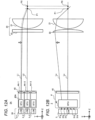
- FIGS. 12A and 12B are diagrams illustrating a configuration of a beam coupling device 2A according to the second embodiment.
- FIG. 12A illustrates a side view of the beam coupling device 2A as viewed from the X direction.
- FIG. 12B illustrates a plan view of the beam coupling device 2A as viewed from the Y direction.
- each LD bar 3 is arranged on the -Z side of a separate optical unit 4A, for example.
- the configuration of the BTU 40A is different from the configuration of the optical unit 4 of the first embodiment.
- the coupling optical system 20 is arranged on the +Z side of the optical unit 4A and includes an axially symmetric condenser lens 21 and a cylindrical lens 22 arranged between the condenser lens 21 and the optical unit 4A.
- FIG. 12B exemplifies the five LDs 31a, 31b, 31c, 31d, and 31e in the LD bar 3.
- the resonance wavelengths of the individual LDs 31a to 31e may be the same.
- the plurality of LDs 31a to 31e in the LD bar 3 are an example of a set of light emitters in the laser light source 30 of the present embodiment.
- the generic term of LDs 31a to 31e may be referred to as "LD 31".
- FIGS. 12A and 12B exemplify a beam coupling position P1 resulted from coupling the light beam by the beam coupling device 2A.
- the beam coupling position P1 is set to a position at which a beam diameter including the light beam emitted from each of the LDs 31a to 31e of all the LD bars 3-1 to 3-3 is minimized, for example.
- an incident end of the optical fiber of the transmission optical system 10 described above is arranged at the beam coupling position P1.
- FIG. 12A exemplifies a chief ray L1 of the light beam from the outer LD bar 3-1 in the Y direction, and a chief ray L2 of the light beam from the central LD bar 3-2.
- FIG. 12B exemplifies a chief ray La of the light beam from the outer LD 31a in the X direction, and a chief ray Lc of the light beam from the central LD 31c.
- the LD 31c central in the X and Y directions has a chief ray Lc parallel to the Z direction similar to the first embodiment, for example.
- the chief ray L1 of the light beam emitted by the outer LD bars 3-1 of the plurality of LD bars 3 arranged in the Y direction is directed inward, in view of increasing the output of the beam coupling device 2A for spatial beam combining, for example.
- Such light ray control can be performed by inclining the outer optical unit 4A-1 or shifting the arrangement of the SAC 45 inward.
- the upper (+Y side) optical unit 4A in the drawing makes the chief ray L1 of the light beam inclined from the Z direction to the lower side (-Y side).
- the beam coupling position P1 in the Y direction where the chief rays L1 and L2 intersect between the LD bars 3 is located on the -Z side from a focal position P0 of the condenser lens 21.
- the optical unit 4A of the beam coupling device 2A of the present embodiment is configured to make the chief ray La of the light beam from the outer LD 31a directed outward.
- the position where the plurality of light beams intersect can be brought closer to the focal point of the condenser lens 21, the beam diameter itself at the coupling of each light beam can be reduced, and the density of the light beam incident on the coupling optical system 20 can be increased.
- the beam coupling position P1 can match the beam coupling position P1 in the X direction and the Y direction.
- optical unit 4A of the beam coupling device 2A according to the second embodiment will be described.
- FIG. 13 illustrates a configuration example of the BT 50A of the optical unit 4A in the second embodiment.
- the optical unit 4A of the present embodiment includes a BT 50A of the configuration example of FIG. 13 , in place of the BT 50 having the pitch Wo on the +Z side smaller than the pitch Wi on the -Z side in the optical unit 4 of the first embodiment.
- FIG. 14 illustrates a cross-sectional view of the XZ plane in the BT 50A of FIG. 13 .
- a pitch Wi on the -Z side is smaller than a pitch Wo on the +Z side.
- the BT 50A of this configuration example is configured so that the pitch Wo between the oblique lens portions 51 on the end face on the +Z side is larger than the pitch Wi on the end face on the -Z side.
- the curved surface shape of the oblique lens portion 51 on the end face on the +Z side can be set to extend the curved surface shape on the -Z side, for example.
- the pitch Wi on the -Z side is set according to the pitch between the LDs 31 in the LD bar 3 as in the BT 50 of the first embodiment, for example.
- the magnitude of the difference between the pitches Wi and Wo may be within the same range as that of the first embodiment.
- the BT 50A and BTU 40A of the present embodiment are also examples of optical units as in the first embodiment.
- FIGS. 15A to 15C illustrate the optical path in the optical unit 4A of the present embodiment, in the same manner as in FIGS. 9A to 9C .
- FIG. 15A corresponds to the A-A cross section of FIG. 13 .
- FIGS. 15B and 15C correspond to the B-B cross-sectional view and the C-C cross-sectional view in FIG. 15A , respectively.
- the BT 50A of the present embodiment faces the SAC 45 on the +Z side and faces the FAC 41 on the -Z side, as in the first embodiment.
- the chief ray La is directed more outward in the X and Y directions as the LD 31a is located more outside in the X direction, according to the pitch Wo of the oblique lens portion 51 on the end face on the +Z side of the BT 50A wherein the pitch Wo is larger than the pitch between LDs 31.
- the inclination of the chief ray La in the Y direction is corrected in the SAC 45 in the same manner as in the first embodiment.
- the chief ray Lc of the outer LD 31c in the X direction can be restricted to the X direction and directed outward.
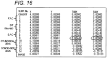
- FIG. 16 illustrates the simulation results of an example of the beam coupling device 2A of the second embodiment.
- the same numerical calculation as in the first embodiment was performed in the simulation environment of the beam coupling device 2A for spatial beam combining.
- the distance between the plurality of optical units 4A was set to 4.8 mm
- the focal length of the SAC 45 was set to 15 mm
- the focal length of the condenser lens 21 was set to 50 mm.
- the same numerical calculation as in the first embodiment was performed by setting that the pitch Wo on the +Z side of the BT 50A is made larger by 318 nm than the pitch Wi on the -Z side.
- the pitch between the pitch Wi on the -Z side of the BT 50A and the LD of the LD bar 3 was 0.225000 mm as in the first embodiment.
- TANX has a positive value of "0.00443" after the exit of the SAC 45, and the chief ray on the +X side is directed outward. Further, the value "0.00003" of "TANY” at this time is sufficiently smaller than the above-mentioned "TANX”. Therefore, it was checked that the outer chief ray in the X direction can be directed outward in the X direction while keeping the inclination in the Y direction slightly.
- the pitch Wi in which the oblique lens portions 51 are arranged on the end face on the -Z side as an example of one end face of both end faces of the BT 50 in the optical axis direction is smaller than the pitch Wo at which the oblique lens portion 51 is arranged on the end face on the +Z side as an example of the other end face.
- the BT 50A of the optical unit 4A can improve the degree of freedom in design for guiding a plurality of light beams.
- the beam coupling device 2A includes a laser light source 30 as an example of the light source, a plurality of optical units 4A, and a coupling optical system 20.
- the laser light source 30 includes LDs 31 which is an example of a plurality of light emitters arranged in the X direction and the Y direction, for example.
- the plurality of optical units 4A are arranged to guide each light beam for each LD bar 3 as a set of LD 31a to LD 31e arranged in the X direction in the laser light source 30.
- the coupling optical system 20 is arranged to couple a plurality of light beams guided to each optical unit 4A.
- the optical unit 4A is arranged so that among both end faces of the BT 50, the end face on the +Z side having a large pitch Wo of the oblique lens portion 51 faces the coupling optical system 20.
- the beam diameter itself at the beam coupling position P1 can be reduced by making the outer chief ray L11 in the X direction directed outward by the optical unit 4A. In this way, by improving the degree of freedom in design by the optical unit 4A, it is possible to improve the beam quality in the coupling device 2A for spatial beam combining.
- the first and second embodiments are described as an example of the technique disclosed in the present application.
- the technique in the present disclosure is not limited thereto, and can also be applied to embodiments in which changes, substitutions, additions, omissions, and the like are made as appropriate.
- other embodiments will be exemplified.
- the configuration of the beam coupling device 2 is not particularly limited to this example.
- the transmission type diffraction element 25 is used for the beam coupling device 2
- the diffraction element 25 is not limited to the transmission side and may be a reflection type.
- the 900 nm band is illustrated as the wavelength band in which the LD 31 emits light; however, the wavelength band of the LD 31 is not particularly limited and may be the 400 nm band, for example.
- the optical unit 4 of the present embodiment even in the optical design of such various beam coupling devices 2 for wavelength beam combining, the light ray direction of the light beam can be controlled such that the BT 50 has the light-condensing function, and the degree of freedom in design can be improved.
- the configuration of the beam coupling device 2A is not particularly limited to this example.
- the beam coupling device 2A for inwardly directing the outer chief ray L1 in the Y direction has been described; however, the chief ray L1 may not be inwardly directed, and may be outwardly directed, for example.
- the cylindrical lens 22 is used for the coupling optical system 20 has been described, but the cylindrical lens 22 may be omitted. According to the optical unit 4A of the present embodiment, even in the optical design of such various coupling devices 2A for spatial beam combining, the degree of freedom in design can be improved.
- optical unit of the present embodiment is not limited to the e coupling device for wavelength beam combining or spatial beam combining, and may be applied to various beam coupling devices.
- the optical unit of the present embodiment can also be applied to a beam coupling device in which wavelength beam combining and spatial beam combining are appropriately used.
- the present disclosure is applicable to various applications in which a plurality of light beams are coupled and used, and is applicable to various laser processing techniques, for example.
Landscapes
- Physics & Mathematics (AREA)
- Optics & Photonics (AREA)
- General Physics & Mathematics (AREA)
- Condensed Matter Physics & Semiconductors (AREA)
- Electromagnetism (AREA)
- Engineering & Computer Science (AREA)
- Plasma & Fusion (AREA)
- Mechanical Engineering (AREA)
- Optical Couplings Of Light Guides (AREA)
- Semiconductor Lasers (AREA)
- Diffracting Gratings Or Hologram Optical Elements (AREA)
- Laser Beam Processing (AREA)
Applications Claiming Priority (2)
| Application Number | Priority Date | Filing Date | Title |
|---|---|---|---|
| JP2019215505 | 2019-11-28 | ||
| PCT/JP2020/025876 WO2021106257A1 (ja) | 2019-11-28 | 2020-07-01 | 光学ユニット、ビーム結合装置およびレーザ加工機 |
Publications (3)
| Publication Number | Publication Date |
|---|---|
| EP4067947A1 EP4067947A1 (en) | 2022-10-05 |
| EP4067947A4 EP4067947A4 (en) | 2023-03-08 |
| EP4067947B1 true EP4067947B1 (en) | 2024-09-04 |
Family
ID=76130448
Family Applications (1)
| Application Number | Title | Priority Date | Filing Date |
|---|---|---|---|
| EP20894129.4A Active EP4067947B1 (en) | 2019-11-28 | 2020-07-01 | Optical unit, beam coupling device, and laser processing machine |
Country Status (5)
| Country | Link |
|---|---|
| US (1) | US11867919B2 (https=) |
| EP (1) | EP4067947B1 (https=) |
| JP (1) | JP7479396B2 (https=) |
| CN (1) | CN114761835A (https=) |
| WO (1) | WO2021106257A1 (https=) |
Family Cites Families (14)
| Publication number | Priority date | Publication date | Assignee | Title |
|---|---|---|---|---|
| US6246524B1 (en) * | 1998-07-13 | 2001-06-12 | Semiconductor Energy Laboratory Co., Ltd. | Beam homogenizer, laser irradiation apparatus, laser irradiation method, and method of manufacturing semiconductor device |
| EP1006382B1 (de) | 1998-10-30 | 2002-09-18 | Lissotschenko, Vitalij | Anordnung und Vorrichtung zur optischen Strahltransformation |
| JP3472249B2 (ja) * | 2000-08-25 | 2003-12-02 | キヤノン株式会社 | 複数の光源を使用する照明装置、照明制御装置及び方法、並びに、露光装置 |
| JP2006171348A (ja) * | 2004-12-15 | 2006-06-29 | Nippon Steel Corp | 半導体レーザ装置 |
| US8804246B2 (en) * | 2008-05-08 | 2014-08-12 | Ii-Vi Laser Enterprise Gmbh | High brightness diode output methods and devices |
| US8536110B2 (en) | 2011-07-02 | 2013-09-17 | Brad Drost | Molded solid industrial cleaning block |
| US8946594B2 (en) * | 2011-11-04 | 2015-02-03 | Applied Materials, Inc. | Optical design for line generation using microlens array |
| US9746679B2 (en) | 2012-02-22 | 2017-08-29 | TeraDiode, Inc. | Wavelength beam combining laser systems utilizing lens roll for chief ray focusing |
| CN102809822B (zh) * | 2012-08-22 | 2015-03-25 | 温州泛波激光有限公司 | 一种激光二极管阵列的光束耦合聚焦装置 |
| JP6327035B2 (ja) * | 2013-08-12 | 2018-05-23 | 大日本印刷株式会社 | 照明装置、投射装置、レンズアレイおよび光学モジュール |
| US10571708B2 (en) * | 2016-02-09 | 2020-02-25 | Mitsubishi Electric Corporation | Beam shaping device and laser oscillator |
| EP3506437A4 (en) * | 2016-08-26 | 2019-11-27 | Panasonic Intellectual Property Management Co., Ltd. | LASER MODULE |
| CN110383607B (zh) * | 2017-03-09 | 2021-03-02 | 三菱电机株式会社 | 波长耦合激光器装置 |
| WO2019163335A1 (ja) * | 2018-02-26 | 2019-08-29 | パナソニックIpマネジメント株式会社 | 光共振器及びレーザ加工機 |
-
2020
- 2020-07-01 EP EP20894129.4A patent/EP4067947B1/en active Active
- 2020-07-01 CN CN202080082052.1A patent/CN114761835A/zh active Pending
- 2020-07-01 WO PCT/JP2020/025876 patent/WO2021106257A1/ja not_active Ceased
- 2020-07-01 JP JP2021561151A patent/JP7479396B2/ja active Active
-
2022
- 2022-05-05 US US17/737,139 patent/US11867919B2/en active Active
Also Published As
| Publication number | Publication date |
|---|---|
| WO2021106257A1 (ja) | 2021-06-03 |
| CN114761835A (zh) | 2022-07-15 |
| JPWO2021106257A1 (https=) | 2021-06-03 |
| US11867919B2 (en) | 2024-01-09 |
| US20220260842A1 (en) | 2022-08-18 |
| JP7479396B2 (ja) | 2024-05-08 |
| EP4067947A4 (en) | 2023-03-08 |
| EP4067947A1 (en) | 2022-10-05 |
Similar Documents
| Publication | Publication Date | Title |
|---|---|---|
| US11353715B2 (en) | Wavelength beam combining laser systems utilizing lens roll for chief ray focusing | |
| US9331457B2 (en) | Semiconductor laser apparatus | |
| US12216291B2 (en) | Systems and methods for alignment of wavelength beam combining resonators | |
| EP3761463A1 (en) | Light resonator and laser processing machine | |
| JP2021524161A (ja) | 波長合成技術用レーザシステムにおけるパワー及びスペクトラムのモニタリング | |
| JP7153862B2 (ja) | 階段状スロー軸コリメータを有するレーザシステム | |
| JP2022508765A5 (https=) | ||
| EP4067947B1 (en) | Optical unit, beam coupling device, and laser processing machine | |
| US12246394B2 (en) | Optical resonator, and laser processing apparatus | |
| JP6268004B2 (ja) | 半導体レーザ装置 | |
| US20220271497A1 (en) | Beam coupling device and laser processing machine | |
| EP4387015A1 (en) | Optical system and laser device, collimator lens | |
| US20250105592A1 (en) | Laser apparatus and laser processing machine | |
| JP2024038535A (ja) | 光共振器及びレーザ加工装置 | |
| US20230163550A1 (en) | Laser system | |
| JP2025081990A (ja) | レーザ発振器及びこれを備えたレーザ加工装置、第1レーザ光の光軸調整方法 | |
| WO2015191451A1 (en) | Wavelength beam combining laser systems utilizing lens roll for chief ray focusing |
Legal Events
| Date | Code | Title | Description |
|---|---|---|---|
| STAA | Information on the status of an ep patent application or granted ep patent |
Free format text: STATUS: THE INTERNATIONAL PUBLICATION HAS BEEN MADE |
|
| PUAI | Public reference made under article 153(3) epc to a published international application that has entered the european phase |
Free format text: ORIGINAL CODE: 0009012 |
|
| STAA | Information on the status of an ep patent application or granted ep patent |
Free format text: STATUS: REQUEST FOR EXAMINATION WAS MADE |
|
| 17P | Request for examination filed |
Effective date: 20220518 |
|
| AK | Designated contracting states |
Kind code of ref document: A1 Designated state(s): AL AT BE BG CH CY CZ DE DK EE ES FI FR GB GR HR HU IE IS IT LI LT LU LV MC MK MT NL NO PL PT RO RS SE SI SK SM TR |
|
| A4 | Supplementary search report drawn up and despatched |
Effective date: 20230207 |
|
| DAV | Request for validation of the european patent (deleted) | ||
| DAX | Request for extension of the european patent (deleted) | ||
| RIC1 | Information provided on ipc code assigned before grant |
Ipc: G02B 5/18 20060101ALI20230201BHEP Ipc: B23K 26/064 20140101ALI20230201BHEP Ipc: G02B 3/00 20060101AFI20230201BHEP |
|
| REG | Reference to a national code |
Ref country code: DE Ref legal event code: R079 Free format text: PREVIOUS MAIN CLASS: G02B0003000000 Ipc: G02B0027100000 Ref country code: DE Ref legal event code: R079 Ref document number: 602020037329 Country of ref document: DE Free format text: PREVIOUS MAIN CLASS: G02B0003000000 Ipc: G02B0027100000 |
|
| GRAP | Despatch of communication of intention to grant a patent |
Free format text: ORIGINAL CODE: EPIDOSNIGR1 |
|
| STAA | Information on the status of an ep patent application or granted ep patent |
Free format text: STATUS: GRANT OF PATENT IS INTENDED |
|
| RIC1 | Information provided on ipc code assigned before grant |
Ipc: G02B 27/12 20060101ALI20240123BHEP Ipc: G02B 27/10 20060101AFI20240123BHEP |
|
| INTG | Intention to grant announced |
Effective date: 20240212 |
|
| GRAS | Grant fee paid |
Free format text: ORIGINAL CODE: EPIDOSNIGR3 |
|
| GRAA | (expected) grant |
Free format text: ORIGINAL CODE: 0009210 |
|
| STAA | Information on the status of an ep patent application or granted ep patent |
Free format text: STATUS: THE PATENT HAS BEEN GRANTED |
|
| AK | Designated contracting states |
Kind code of ref document: B1 Designated state(s): AL AT BE BG CH CY CZ DE DK EE ES FI FR GB GR HR HU IE IS IT LI LT LU LV MC MK MT NL NO PL PT RO RS SE SI SK SM TR |
|
| REG | Reference to a national code |
Ref country code: GB Ref legal event code: FG4D |
|
| REG | Reference to a national code |
Ref country code: CH Ref legal event code: EP |
|
| REG | Reference to a national code |
Ref country code: IE Ref legal event code: FG4D |
|
| REG | Reference to a national code |
Ref country code: DE Ref legal event code: R096 Ref document number: 602020037329 Country of ref document: DE |
|
| REG | Reference to a national code |
Ref country code: LT Ref legal event code: MG9D |
|
| REG | Reference to a national code |
Ref country code: NL Ref legal event code: MP Effective date: 20240904 |
|
| PG25 | Lapsed in a contracting state [announced via postgrant information from national office to epo] |
Ref country code: NO Free format text: LAPSE BECAUSE OF FAILURE TO SUBMIT A TRANSLATION OF THE DESCRIPTION OR TO PAY THE FEE WITHIN THE PRESCRIBED TIME-LIMIT Effective date: 20241204 |
|
| PG25 | Lapsed in a contracting state [announced via postgrant information from national office to epo] |
Ref country code: GR Free format text: LAPSE BECAUSE OF FAILURE TO SUBMIT A TRANSLATION OF THE DESCRIPTION OR TO PAY THE FEE WITHIN THE PRESCRIBED TIME-LIMIT Effective date: 20241205 Ref country code: PL Free format text: LAPSE BECAUSE OF FAILURE TO SUBMIT A TRANSLATION OF THE DESCRIPTION OR TO PAY THE FEE WITHIN THE PRESCRIBED TIME-LIMIT Effective date: 20240904 Ref country code: FI Free format text: LAPSE BECAUSE OF FAILURE TO SUBMIT A TRANSLATION OF THE DESCRIPTION OR TO PAY THE FEE WITHIN THE PRESCRIBED TIME-LIMIT Effective date: 20240904 |
|
| PG25 | Lapsed in a contracting state [announced via postgrant information from national office to epo] |
Ref country code: BG Free format text: LAPSE BECAUSE OF FAILURE TO SUBMIT A TRANSLATION OF THE DESCRIPTION OR TO PAY THE FEE WITHIN THE PRESCRIBED TIME-LIMIT Effective date: 20240904 |
|
| PG25 | Lapsed in a contracting state [announced via postgrant information from national office to epo] |
Ref country code: LV Free format text: LAPSE BECAUSE OF FAILURE TO SUBMIT A TRANSLATION OF THE DESCRIPTION OR TO PAY THE FEE WITHIN THE PRESCRIBED TIME-LIMIT Effective date: 20240904 |
|
| PG25 | Lapsed in a contracting state [announced via postgrant information from national office to epo] |
Ref country code: HR Free format text: LAPSE BECAUSE OF FAILURE TO SUBMIT A TRANSLATION OF THE DESCRIPTION OR TO PAY THE FEE WITHIN THE PRESCRIBED TIME-LIMIT Effective date: 20240904 |
|
| PG25 | Lapsed in a contracting state [announced via postgrant information from national office to epo] |
Ref country code: ES Free format text: LAPSE BECAUSE OF FAILURE TO SUBMIT A TRANSLATION OF THE DESCRIPTION OR TO PAY THE FEE WITHIN THE PRESCRIBED TIME-LIMIT Effective date: 20240904 Ref country code: RS Free format text: LAPSE BECAUSE OF FAILURE TO SUBMIT A TRANSLATION OF THE DESCRIPTION OR TO PAY THE FEE WITHIN THE PRESCRIBED TIME-LIMIT Effective date: 20241204 |
|
| PG25 | Lapsed in a contracting state [announced via postgrant information from national office to epo] |
Ref country code: RS Free format text: LAPSE BECAUSE OF FAILURE TO SUBMIT A TRANSLATION OF THE DESCRIPTION OR TO PAY THE FEE WITHIN THE PRESCRIBED TIME-LIMIT Effective date: 20241204 Ref country code: PL Free format text: LAPSE BECAUSE OF FAILURE TO SUBMIT A TRANSLATION OF THE DESCRIPTION OR TO PAY THE FEE WITHIN THE PRESCRIBED TIME-LIMIT Effective date: 20240904 Ref country code: NO Free format text: LAPSE BECAUSE OF FAILURE TO SUBMIT A TRANSLATION OF THE DESCRIPTION OR TO PAY THE FEE WITHIN THE PRESCRIBED TIME-LIMIT Effective date: 20241204 Ref country code: LV Free format text: LAPSE BECAUSE OF FAILURE TO SUBMIT A TRANSLATION OF THE DESCRIPTION OR TO PAY THE FEE WITHIN THE PRESCRIBED TIME-LIMIT Effective date: 20240904 Ref country code: HR Free format text: LAPSE BECAUSE OF FAILURE TO SUBMIT A TRANSLATION OF THE DESCRIPTION OR TO PAY THE FEE WITHIN THE PRESCRIBED TIME-LIMIT Effective date: 20240904 Ref country code: GR Free format text: LAPSE BECAUSE OF FAILURE TO SUBMIT A TRANSLATION OF THE DESCRIPTION OR TO PAY THE FEE WITHIN THE PRESCRIBED TIME-LIMIT Effective date: 20241205 Ref country code: FI Free format text: LAPSE BECAUSE OF FAILURE TO SUBMIT A TRANSLATION OF THE DESCRIPTION OR TO PAY THE FEE WITHIN THE PRESCRIBED TIME-LIMIT Effective date: 20240904 Ref country code: ES Free format text: LAPSE BECAUSE OF FAILURE TO SUBMIT A TRANSLATION OF THE DESCRIPTION OR TO PAY THE FEE WITHIN THE PRESCRIBED TIME-LIMIT Effective date: 20240904 Ref country code: BG Free format text: LAPSE BECAUSE OF FAILURE TO SUBMIT A TRANSLATION OF THE DESCRIPTION OR TO PAY THE FEE WITHIN THE PRESCRIBED TIME-LIMIT Effective date: 20240904 |
|
| REG | Reference to a national code |
Ref country code: AT Ref legal event code: MK05 Ref document number: 1720985 Country of ref document: AT Kind code of ref document: T Effective date: 20240904 |
|
| PG25 | Lapsed in a contracting state [announced via postgrant information from national office to epo] |
Ref country code: NL Free format text: LAPSE BECAUSE OF FAILURE TO SUBMIT A TRANSLATION OF THE DESCRIPTION OR TO PAY THE FEE WITHIN THE PRESCRIBED TIME-LIMIT Effective date: 20240904 |
|
| PG25 | Lapsed in a contracting state [announced via postgrant information from national office to epo] |
Ref country code: PT Free format text: LAPSE BECAUSE OF FAILURE TO SUBMIT A TRANSLATION OF THE DESCRIPTION OR TO PAY THE FEE WITHIN THE PRESCRIBED TIME-LIMIT Effective date: 20250106 Ref country code: IS Free format text: LAPSE BECAUSE OF FAILURE TO SUBMIT A TRANSLATION OF THE DESCRIPTION OR TO PAY THE FEE WITHIN THE PRESCRIBED TIME-LIMIT Effective date: 20250104 |
|
| PG25 | Lapsed in a contracting state [announced via postgrant information from national office to epo] |
Ref country code: RO Free format text: LAPSE BECAUSE OF FAILURE TO SUBMIT A TRANSLATION OF THE DESCRIPTION OR TO PAY THE FEE WITHIN THE PRESCRIBED TIME-LIMIT Effective date: 20240904 Ref country code: SM Free format text: LAPSE BECAUSE OF FAILURE TO SUBMIT A TRANSLATION OF THE DESCRIPTION OR TO PAY THE FEE WITHIN THE PRESCRIBED TIME-LIMIT Effective date: 20240904 |
|
| PG25 | Lapsed in a contracting state [announced via postgrant information from national office to epo] |
Ref country code: AT Free format text: LAPSE BECAUSE OF FAILURE TO SUBMIT A TRANSLATION OF THE DESCRIPTION OR TO PAY THE FEE WITHIN THE PRESCRIBED TIME-LIMIT Effective date: 20240904 Ref country code: EE Free format text: LAPSE BECAUSE OF FAILURE TO SUBMIT A TRANSLATION OF THE DESCRIPTION OR TO PAY THE FEE WITHIN THE PRESCRIBED TIME-LIMIT Effective date: 20240904 |
|
| PG25 | Lapsed in a contracting state [announced via postgrant information from national office to epo] |
Ref country code: CZ Free format text: LAPSE BECAUSE OF FAILURE TO SUBMIT A TRANSLATION OF THE DESCRIPTION OR TO PAY THE FEE WITHIN THE PRESCRIBED TIME-LIMIT Effective date: 20240904 |
|
| PG25 | Lapsed in a contracting state [announced via postgrant information from national office to epo] |
Ref country code: SK Free format text: LAPSE BECAUSE OF FAILURE TO SUBMIT A TRANSLATION OF THE DESCRIPTION OR TO PAY THE FEE WITHIN THE PRESCRIBED TIME-LIMIT Effective date: 20240904 Ref country code: IT Free format text: LAPSE BECAUSE OF FAILURE TO SUBMIT A TRANSLATION OF THE DESCRIPTION OR TO PAY THE FEE WITHIN THE PRESCRIBED TIME-LIMIT Effective date: 20240904 |
|
| REG | Reference to a national code |
Ref country code: DE Ref legal event code: R097 Ref document number: 602020037329 Country of ref document: DE |
|
| PG25 | Lapsed in a contracting state [announced via postgrant information from national office to epo] |
Ref country code: DK Free format text: LAPSE BECAUSE OF FAILURE TO SUBMIT A TRANSLATION OF THE DESCRIPTION OR TO PAY THE FEE WITHIN THE PRESCRIBED TIME-LIMIT Effective date: 20240904 |
|
| PLBE | No opposition filed within time limit |
Free format text: ORIGINAL CODE: 0009261 |
|
| STAA | Information on the status of an ep patent application or granted ep patent |
Free format text: STATUS: NO OPPOSITION FILED WITHIN TIME LIMIT |
|
| 26N | No opposition filed |
Effective date: 20250605 |
|
| PG25 | Lapsed in a contracting state [announced via postgrant information from national office to epo] |
Ref country code: SE Free format text: LAPSE BECAUSE OF FAILURE TO SUBMIT A TRANSLATION OF THE DESCRIPTION OR TO PAY THE FEE WITHIN THE PRESCRIBED TIME-LIMIT Effective date: 20240904 |
|
| REG | Reference to a national code |
Ref country code: DE Ref legal event code: R119 Ref document number: 602020037329 Country of ref document: DE |
|
| REG | Reference to a national code |
Ref country code: CH Ref legal event code: H13 Free format text: ST27 STATUS EVENT CODE: U-0-0-H10-H13 (AS PROVIDED BY THE NATIONAL OFFICE) Effective date: 20260224 |
|
| PG25 | Lapsed in a contracting state [announced via postgrant information from national office to epo] |
Ref country code: LU Free format text: LAPSE BECAUSE OF NON-PAYMENT OF DUE FEES Effective date: 20250701 |
|
| GBPC | Gb: european patent ceased through non-payment of renewal fee |
Effective date: 20250701 |
|
| REG | Reference to a national code |
Ref country code: BE Ref legal event code: MM Effective date: 20250731 |
|
| PG25 | Lapsed in a contracting state [announced via postgrant information from national office to epo] |
Ref country code: GB Free format text: LAPSE BECAUSE OF NON-PAYMENT OF DUE FEES Effective date: 20250701 |
|
| PG25 | Lapsed in a contracting state [announced via postgrant information from national office to epo] |
Ref country code: DE Free format text: LAPSE BECAUSE OF NON-PAYMENT OF DUE FEES Effective date: 20260203 |
|
| PG25 | Lapsed in a contracting state [announced via postgrant information from national office to epo] |
Ref country code: BE Free format text: LAPSE BECAUSE OF NON-PAYMENT OF DUE FEES Effective date: 20250731 |
|
| PG25 | Lapsed in a contracting state [announced via postgrant information from national office to epo] |
Ref country code: FR Free format text: LAPSE BECAUSE OF NON-PAYMENT OF DUE FEES Effective date: 20250731 |
|
| PG25 | Lapsed in a contracting state [announced via postgrant information from national office to epo] |
Ref country code: CH Free format text: LAPSE BECAUSE OF NON-PAYMENT OF DUE FEES Effective date: 20250731 |