EP4067272A1 - Transport system - Google Patents
Transport system Download PDFInfo
- Publication number
- EP4067272A1 EP4067272A1 EP22163616.0A EP22163616A EP4067272A1 EP 4067272 A1 EP4067272 A1 EP 4067272A1 EP 22163616 A EP22163616 A EP 22163616A EP 4067272 A1 EP4067272 A1 EP 4067272A1
- Authority
- EP
- European Patent Office
- Prior art keywords
- section
- transport
- guide
- along
- roller
- Prior art date
- Legal status (The legal status is an assumption and is not a legal conclusion. Google has not performed a legal analysis and makes no representation as to the accuracy of the status listed.)
- Pending
Links
- 102100040610 Dynein regulatory complex subunit 4 Human genes 0.000 claims description 16
- 101000816970 Homo sapiens Dynein regulatory complex subunit 4 Proteins 0.000 claims description 16
- 101100083066 Candida albicans (strain SC5314 / ATCC MYA-2876) PGA5 gene Proteins 0.000 claims description 14
- 239000000969 carrier Substances 0.000 claims description 11
- 102100036716 Glycosylphosphatidylinositol anchor attachment 1 protein Human genes 0.000 description 17
- 101001072432 Homo sapiens Glycosylphosphatidylinositol anchor attachment 1 protein Proteins 0.000 description 17
- 230000008878 coupling Effects 0.000 description 10
- 238000010168 coupling process Methods 0.000 description 10
- 238000005859 coupling reaction Methods 0.000 description 10
- 238000000034 method Methods 0.000 description 6
- 230000000284 resting effect Effects 0.000 description 4
- 101100208421 Candida albicans (strain SC5314 / ATCC MYA-2876) TMP1 gene Proteins 0.000 description 3
- 101100182720 Homo sapiens LY6E gene Proteins 0.000 description 3
- 102100032131 Lymphocyte antigen 6E Human genes 0.000 description 3
- 101100153788 Schizosaccharomyces pombe (strain 972 / ATCC 24843) tpx1 gene Proteins 0.000 description 3
- 101150048440 TSA1 gene Proteins 0.000 description 3
- 102100036683 Growth arrest-specific protein 1 Human genes 0.000 description 2
- 102100036685 Growth arrest-specific protein 2 Human genes 0.000 description 2
- 101001072723 Homo sapiens Growth arrest-specific protein 1 Proteins 0.000 description 2
- 101001072710 Homo sapiens Growth arrest-specific protein 2 Proteins 0.000 description 2
- 230000036316 preload Effects 0.000 description 2
- 230000001419 dependent effect Effects 0.000 description 1
- 238000011161 development Methods 0.000 description 1
- 230000018109 developmental process Effects 0.000 description 1
- 230000000694 effects Effects 0.000 description 1
- 230000004907 flux Effects 0.000 description 1
- 238000009434 installation Methods 0.000 description 1
- 230000003993 interaction Effects 0.000 description 1
- 238000004519 manufacturing process Methods 0.000 description 1
- 238000012986 modification Methods 0.000 description 1
- 230000004048 modification Effects 0.000 description 1
- 239000011343 solid material Substances 0.000 description 1
Images


Classifications
-
- B—PERFORMING OPERATIONS; TRANSPORTING
- B65—CONVEYING; PACKING; STORING; HANDLING THIN OR FILAMENTARY MATERIAL
- B65G—TRANSPORT OR STORAGE DEVICES, e.g. CONVEYORS FOR LOADING OR TIPPING, SHOP CONVEYOR SYSTEMS OR PNEUMATIC TUBE CONVEYORS
- B65G54/00—Non-mechanical conveyors not otherwise provided for
- B65G54/02—Non-mechanical conveyors not otherwise provided for electrostatic, electric, or magnetic
-
- B—PERFORMING OPERATIONS; TRANSPORTING
- B65—CONVEYING; PACKING; STORING; HANDLING THIN OR FILAMENTARY MATERIAL
- B65G—TRANSPORT OR STORAGE DEVICES, e.g. CONVEYORS FOR LOADING OR TIPPING, SHOP CONVEYOR SYSTEMS OR PNEUMATIC TUBE CONVEYORS
- B65G23/00—Driving gear for endless conveyors; Belt- or chain-tensioning arrangements
- B65G23/22—Arrangements or mountings of driving motors
- B65G23/23—Arrangements or mountings of driving motors of electric linear motors
Definitions
- the present invention relates to a transport system for transporting objects along a transport route.
- the present invention relates to a transport system with an improved electromagnetic drive system.
- Revolving transport devices are known from the prior art in various configurations.
- the US 6,876,107 B2 a circulating transport device in which a large number of coils are arranged on the transport path.
- the coils are arranged directly adjacent to one another and are designed in a curved area of the transport path in such a way that they are arranged directly next to one another there.
- the coils When viewed from above, the coils have a shape that follows in the direction of the inside of the curve.
- a transport device for transporting a product comprising a large number of conveying elements that can be moved independently of one another for conveying products, a stationary, circumferentially arranged running rail which defines a running path with at least one running track for the conveying element, and a linear motor drive device for driving the conveying elements, each conveying element has permanent magnets which are operatively connected to coils of the linear drive device and each conveying element has at least a first sub-element and a second sub-element which are connected to one another in an articulated manner by means of joints.
- Each conveyor element has a modular structure and the individual sub-elements have the same basic structure. A joint axis of each joint is arranged parallel to the raceway.
- the conveyor here comprises a first guide unit with a first roller, a second roller and a first turntable, wherein the first turntable first roller and the second roller are rotatably mounted and bear against the running rail, the running rail having a rail longitudinal axis running in the longitudinal direction.
- the first turntable is rotatably mounted about a turntable axis, the turntable axis being inclined, in particular perpendicular, to the rail longitudinal axis.
- a disadvantage of these known solutions is insufficient mechanical stability for transporting heavier loads than objects by means of at least one runner along the running rail. Also for the transport of heavy objects by means of the at least one runner, it should be possible to guide the runner along the transport path with high precision and as little tolerance as possible.
- the high costs that arise from the provision and installation of an electromagnetic drive in such transport systems are disadvantageous. These high costs are regularly accepted in order to be able to realize the advantages of, for example, high-precision controllability associated by means of an electromagnetic drive—and that separately and independently for each individual runner—in a transport system.
- the object of the present invention is therefore to provide a transport system for transporting objects along a transport route which avoids the disadvantages known from the prior art and at the same time enables high-precision feeding of the runners while at the same time significantly reducing the costs of the transport system.
- a transport system according to patent claim 1 is designed to solve this problem.
- the dependent claims relate to particularly advantageous embodiment variants of the invention.
- the essential aspect of the present invention is to be seen in proposing a transport system for transporting objects along a transport route, the transport route being formed from at least a first transport route section and at least a second transport route section.
- the transport system comprises at least one stationary running rail and at least one runner, which can be moved along the running rail, for transporting the objects along the transport route.
- the transport system also includes an electromagnetic drive for driving the at least one runner along the first transport route section by means of electromagnetic forces, with the electromagnetic drive having a large number of stationary coil elements and at least one permanent magnet, with the stationary coil elements of the electromagnetic drive on the stationary running rail exclusively along the first transport path section are provided and the at least one permanent magnet is provided on the at least one rotor.
- the transport system has a mechanical drive for driving the at least one runner along the second transport route section by means of mechanical forces.
- the electromagnetic drive for driving the runners is only provided along the first transport path section, while a mechanical drive that is significantly less expensive than the electromagnetic drive is provided along the second transport path section.
- the runner can thus be used with high precision along the first transport route section by means of the electromagnetic drive to the desired position for conveying objects, components or tools and this runner can then be returned again by means of the mechanical drive.
- the mechanical drive is provided according to the invention for the technically non-critical return, where high precision is not important. However, this means that the cost-intensive components of the electromagnetic drive can be dispensed with over long distances along the transport route, and instead a mechanical drive, such as a toothed belt drive, can be used here.
- the running rail has a first and second guide device, at least in sections along the first and/or the second transport route section, by means of which the at least one runner is provided on both sides with two guide devices that are spaced apart from one another and each run between the first and second guide device Joint axes is guided.
- the joint axes are each guided at a first free end with a first guiding and bearing device in the first guiding device and at a respective second free end with a second guiding and bearing device in the second guiding device.
- the first and second guide and bearing devices each comprise at least one first and second roller, which are guided between a first and second guide surface of the respective guide device that is opposite one another and runs parallel to the joint axes.
- the respective first roller rests in a first contact section of the first guide surface and the respective second roller rests in a second contact section of the second guide surface and are guided in a prestressed manner with respect to one another, with the first and second contact sections being offset from one another along the joint axes and being opposite one another. Due to the mutually prestressed guidance of the rollers of the guidance and bearing device in the first and second guidance device, even when recording Heavier objects on or at the runner allows a high-precision and tolerance-free as possible guidance of the runner along the transport route.
- the transport route is designed to run endlessly with a first and second arcuate section and a first and second straight section, the first transport route section being provided at least on the first straight section.
- the second transport path section is formed at least on the second straight section and at least in sections on the first and second curved section.
- the first transport route section of the transport route is formed by the first straight section and the second transport route section is formed by the two curved sections and the second straight section connecting these curved sections.
- the electromagnetic drive for driving the at least one rotor by means of electromagnetic forces is provided along the first transport route section designed as the first straight section and/or along the second straight section designed as the two curved sections and the second straight section connecting these curved sections second transport route section, the mechanical drive is provided for driving the at least one rotor by means of mechanical forces.
- the respective two free ends of the two joint axes in the first and second guide device are guided in two guide planes oriented opposite one another and parallel to the transport path.
- the respective first and second rollers of the corresponding first guiding and bearing device are rotatable about the respective joint axis and are provided directly adjacent thereto in the region of the respective first free end.
- the respective first and second roller of the corresponding second guiding and bearing device are rotatable about the respective joint axis and are provided directly adjacent thereto in the area of the respective second free end.
- the respective first roller of the first guiding and bearing device is guided in the first guide device, bearing against the first contact section of the first guide surface, prestressed against the second roller that rests on the second contact section of the second guide surface and the respective first roller of the second guiding and bearing device is guided prestressed against the respective second roller in contact with the second contact section of the second guide surface in the second guide device.
- the respective first and second roller of the first guiding and bearing device of the corresponding joint axis are guided in a pretensioned manner relative to the respective first and second roller of the second guiding and bearing device of the corresponding joint axis.
- the first guide device has a first guide space between the first and second guide surface, which springs back into the first guide space in the area of the first and second contact surface, in that the first guide space is stepped in this area .
- the second guide device has a second guide space between the first and second guide surface, which springs back into the second guide space in the area of the first and second contact surface, in that the second guide space is stepped in this area .
- the rollers have external diameters that are identical to one another.
- all rollers are each mounted rotatably about the corresponding joint axis by means of two roller layers.
- the electromagnetic drive being designed as a linear drive, preferably as a long-stator linear drive.
- the runner has at least four further articulation axes on an underside opposite the top side, which are perpendicular to the first two articulation axes in their respective longitudinal extent and which lie opposite one another in pairs along a guide rail.
- a rotatable roller to be arranged at the respective free ends of the joint axes.
- the corresponding running surfaces of the running rollers run perpendicular to the running surfaces of the running rollers.
- all rollers are identical to one another and preferably identical to the rollers.
- all rollers are each mounted rotatably about the corresponding joint axis by means of two roller bearings.
- the guide rail is provided on the upper side of the drive module of the running rail along its longitudinal extent and is in operative engagement with the running rollers arranged on the underside of the runner.
- the guide rail forms a lateral guide for the runner, which during its movement on both sides and in contact along the transport route with its rollers along the guide rail or rolls off.
- the first and/or second articulation axis of the runner has a first and second articulation axis section at the first and second free end, with the first articulation axis section providing a first rotational axis for the respective first roller and the each second joint axis section forms a second axis of rotation for the respective second roller, and wherein the respective first axis of rotation is offset, in particular offset parallel, to the respective second axis of rotation.
- first and/or the second joint axis is designed as an eccentric axis in the area of the respective joint axis sections.
- the mechanical drive for driving the at least one runner by means of mechanical forces has a motor-driven transport element that rotates endlessly along the transport route and on which several carriers are arranged, which move with the transport element and wherein the carriers are in pushing active engagement with the at least one runner exclusively along the second transport path section.
- the mechanical drive has several deflection devices, for example in the form of deflection rollers, which guide and deflect the transport element, which runs endlessly within the running rail, in such a way that the carriers moved with the transport element only in the area of the second transport section with the at least one runner in mechanical operative engagement.
- the mechanical drive is designed as a belt drive, which has several carriers arranged on a transport element designed as a belt, which are in pushing active engagement with the at least one runner along the second transport path section.
- the respective driver of the transport element designed as a belt is in mechanical operative engagement with the signal generator of the at least one rotor the driver pushes the at least one runner on the signal transmitter along the second transport route section in the transport direction.
- locked is understood to mean an intermittent movement which, in contrast to a continuous movement, is characterized by stepwise or periodically recurring movement sequences, specifically with a standstill after or before each movement step.
- An intermittently moving element which can be a runner moving by a defined distance, for example, completes a movement profile in which the runner is periodically accelerated to a certain speed with almost no jolts and/or jolts and then braked again.
- substantially or “approximately” in the context of the invention means deviations from the exact value in each case by +/-10%, preferably by +/-5% and/or deviations in the form of changes that are insignificant for the function.
- aspects have been described in the context of a device, it is understood that these aspects also represent a description of the corresponding method, so that a block or a component of a device is also to be understood as a corresponding method step or as a feature of a method step . Similarly, aspects described in connection with or as a method step also constitute a description of a corresponding block or detail or feature of a corresponding device.
- Some or all of the method steps may be performed by hardware apparatus (or using a hardware apparatus) such as B. a microprocessor, a programmable computer or an electronic circuit. In some embodiments, some or more of the essential process steps can be performed by such an apparatus.
- 1 designates a transport system for transporting objects along a transport route TS.
- the transport route TS consists of at least one first transport route section TS1 and at least one second transport route section TS2 formed or has the first and second transport route section TS1, TS2.
- the transport system 1 also includes a stationary rail 2 and at least one runner 3 that can be moved along the rail 2 for transporting the objects along the transport route TS.
- the movement path of the running rail 2 is defined by the course of the transport route TS, or its first and second transport route section TS1, TS2.
- the transport system 1 comprises an electromagnetic drive 4 for driving the at least one runner 3 along the first transport route section TS1 by means of electromagnetic forces.
- the electromagnetic drive 4 of the transport system 1 can also have at least one, but preferably several identically designed drive modules 5, which can be provided along the first transport route section TS1 adjacent to the transport route TS in modular form and each drive module 5 can be arranged next to one another.
- the running rail 2 is also designed in a modular manner and comprises several running rail modules 2.1 which can be connected to one another according to the principle of a modular system.
- a running rail module 2.1 of the first transport route section TS1 can thus be assigned its own drive module 5, which can be assembled according to the principle of a rail connector system.
- the drive module(s) 5 is/are provided as a part or component part of the running rail 2 along the first transport route section TS1.
- the transport system 1 includes the electromagnetic drive 4 advantageously exclusively along the first transport route section TS1 in order to drive the runner 3 by means of electromagnetic forces.
- the electromagnetic drive 4 has a large number of stationary coil elements 9 and at least one permanent magnet 8, with the stationary coil elements 9 of the electromagnetic drive 4 on the stationary running rail 2 being provided exclusively along the first transport route section TS1 and the at least one permanent magnet 8 on the at least a rotor 3 is provided,
- the transport system 1 can have a plurality of runners 3 which can be of identical design to one another, it being possible for the plurality of runners 3 to be provided on the running rail 2 at a distance from one another.
- Each rotor 3 can be moved by means of the electromagnetic drive 4 are moved along the first transport route section TS1 independently of the other runners 3 provided, preferably in each case autonomously.
- the electromagnetic drive 4 comprises a linear motor 6 with a stator 7, at least one permanent magnet 8 and a central control device not shown in detail.
- the stator 7 can be formed by a large number of coil elements 9 that are provided separately and at a distance from one another on the running rail 2 and can be energized, while the at least one permanent magnet 8 is arranged on the at least one rotor 3 .
- the coil elements 9 that can be energized are arranged next to one another in the respective drive module 5 .
- Each drive module 5 is connected to the running rail 2 or is designed as part or component part of the running rail 2 .
- the energizable coil elements 9 are arranged in a row running parallel to the running rail 2 .
- the at least one permanent magnet 8 can be provided on the at least one rotor 3 in such a way that it is arranged to the side of the stator 7 .
- the electromagnetic drive 4 has a large number of stationary coil elements 9, which form the stator 7, and at least one permanent magnet 8, with the stationary coil elements 9 on the stationary running rail 2 and the at least one permanent magnet 8 on the at least one rotor 3 are arranged.
- the control device is electrically connected to the stator 7 and designed to vary a coil current through a predefined number of coil elements 9, ie a current flow through the predefined number of coil elements 9.
- the coil current generates an alternating magnetic field that interacts with the at least one permanent magnet 8 .
- the control device is designed to control and/or regulate the movement of the at least one runner 3 along the transport section TS, specifically for each runner 3 separately and independently of the other runners 3.
- the electromagnetic drive 4 is thus designed as a linear drive, more specifically as a long-stator linear drive.
- control device controls and/or regulates the coil currents through the coil elements 9 in such a way that, via the interaction of the permanent magnets 8 with the traveling magnetic field generated by the coil elements 9, a force directed along or along the drive module 5 is exerted on the at least one rotor 3 is exercised.
- transport system 1 also has a mechanical drive 15, described in more detail below, for driving the at least one runner 3 along the second transport route section TS2 by means of mechanical forces.
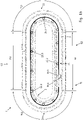
- the transport stretch TS is designed as an endlessly circulating transport stretch TS, which in particular defines an oval course for the running rail 2 .
- the transport route TS has a first curved section B1, a second curved section B2 and a first straight section G1 and a second straight section G2.
- the two straight sections G1, G2 are provided between the first and second arcuate sections B1, B2 and connect the respective free ends of the two arcuate sections B1, B2 to one another in such a way that the running rail 2 forms an essentially oval, closed loop for the runners 3 trains.
- the transport route TS thus includes the two straight sections G1, G2 and the two curved sections B1, B2.
- the first transport route section TSA1 of the transport route TS is advantageously formed by the first straight section G1 and the second transport route section TS2 is formed by the two curved sections B1, B2 and the second straight section G2 connecting these curved sections B1, B2.
- the electromagnetic drive 3 for driving the runners 2 by means of electromagnetic forces is thus provided along the first transport route section TS1 designed as a first straight section G1. Furthermore, the mechanical drive 15 for driving the runners 2 by means of mechanical forces is provided along the second transport path section TS2 configured as the two arcuate sections B1, B2 and the second straight line section G2 connecting these arcuate sections B1, B2.
- the electromechanical drive 3 in the area of the first transport route section TS1 is operatively connected to the runners 2 in such a way that they are driven along the first transport route section TS1 by means of electromagnetic forces
- the mechanical drive 15 in the area of the second transport route section TS2 is connected to the runners 2 is operatively connected in such a way that it is driven along the second transport route section TS2 by means of mechanical forces.
- the first transport route section TSA1 of the transport route TS is formed by the first straight section G1 and a section of the first and/or second curved section B1, B2 and the second Transport route section TS2 through the remaining arcuate sections B1, B2 and the second straight section G2 connecting these arcuate sections B1, B2.
- the first transport route section TSA1 of the transport route TS is formed by the first straight section G1 and all of the two arcuate sections B1, B2, and the second transport route section TS2 is formed by the second straight section G2 connecting the two arcuate sections B1, B2.
- the mechanical drive 15 for driving the runners 2 by means of mechanical forces can have a motor-driven transport element 15.1 that revolves endlessly along the transport section TS, on which several carriers 15.2 are arranged, which move with the transport element 15.1 and with the carriers 15.2 exclusively along of the second transport section TS2 are in pushing active engagement with the runners 2.
- a plurality of deflection devices 15.3, for example in the form of deflection rollers, can preferably be provided here, which guide and deflect the transport element 15.1, which preferably rotates endlessly within the running rail 2, in such a way that the drivers 15.2 moving with the transport element 15.1 only in the area of the second transport route section TS2 with the Runners 2 are in mechanical active engagement.
- the mechanical drive 15 can be embodied as a belt drive, which has a plurality of carriers 15.2 arranged on a transport element 15.1 designed as a belt, which are in pushing active engagement with the runners 2 along the second transport path section TS2.
- the respective driver 15.2 of the transport element 15.1 designed as a belt can be in mechanical operative engagement with the signal transmitter 13 of the corresponding runner 2, in that the driver 15.2 pushes the runner 2 on the signal transmitter 13 along the second transport route section TS2 in the transport direction.
- a spring-loaded mechanical coupling element provided on the signal transmitter 13 can be provided for this purpose.
- the mechanical coupling element can be shifted between a gripping position and a release position, preferably in the longitudinal direction of the signal transmitter 13.
- the coupling element grips a driver 15.2, while the coupling element releases this driver 15.2 again in the release position.
- the mechanical coupling element can be held in the gripping position by means of a spring force, and must be deflected for the release position against the spring force from the gripping position into the release position.
- the thus achievable, or permissible, adjusting movement between the gripping position and the release position is defined by an elongated hole, which is the stop between the two positions of the coupling element determines.
- the coupling element is moved against the spring force in the direction of the transport element 15.1 in such a way that the coupling element can engage behind a corresponding driver 15.2.
- the coupling element is then pressed by the spring force into its gripping position and moved in a direction opposite thereto, so that the driver 15.2 that is gripped behind is pulled in the direction of the signal transmitter 13.
- the coupling element grips the driver in a form-fitting and/or contact-fitting manner in the gripping position.
- the mechanical drive 15 can also have a link chain instead of the belt 15.1, ie it can be designed as a chain drive.
- each of the runners 3 comprises a base body GK on its respective upper side 3.1 a transport or holding surface TF, on which a receptacle (not shown in the figures) can preferably be provided for receiving objects (e.g. workpieces or other Products) is provided, which can be moved with the circulating runners 3 in and/or counter to a transport direction A along the transport route TS.
- a receptacle not shown in the figures
- objects e.g. workpieces or other Products
- each runner 3 comprises an essentially rectangular base body GK, on the upper side 3.1 of which a transport or holding surface TF is formed.
- each runner 3 has first and second articulation axes GA1 and GA2 spaced apart from one another, viewed in the longitudinal direction of the transport section TS.
- the respective joint axes GA1 and GA2 in turn run in their respective longitudinal extent transversely, preferably perpendicularly, to the longitudinal extent of the transport section TS.
- the longitudinal extension of the first joint axis GA1 preferably runs parallel to the longitudinal extension of the second joint axis GA2.
- the respective joint axis GA1, GA2 advantageously has a first guide and bearing device 32.1, 32.2 on its corresponding first free end GAS11, GAS21 and a corresponding second guide and bearing device 33.1, 33.2 on its corresponding second free end GAS12, GAS22.
- the first articulated axis GA1 has the first guide and bearing device 32.1 at its first free end GAS11 and the second guide and bearing device 33.1 at its second free end GAS12
- the second articulated axis GA2 at its first free end GAS21 has the first guiding and bearing device 32.2 and at its second free end GAS22 the second guiding and bearing device 33.2.
- first and second guiding and bearing devices 32.1, 32.2, 33.1, 33.2 each comprise at least one first and one second roller 34, 35, 36, 37. More in detail, the first guide and bearing device 32.1 of the first joint axis GA1 includes the first and second rollers 34 and 35 at its first free end GAS11, while the second guide and bearing device 33.1 of the first joint axis GA1 at the second free end GAS12 includes the first and second rollers 36 and 37 are provided.
- first guiding and bearing device 33.1 of the second joint axis GA2 comprises the first and second rollers 34 and 35 at its first free end GAS21, while the first guiding and bearing device 33.2 of the second joint axis GA2 at the second free end GAS22 includes the first and second rollers 36 and 37 are provided.
- rollers 34 and 35 are identical to one another and identical to the two other rollers 35 and 36 .
- the rollers 34 and 35 or 36 and 37 have an identical diameter in the area of the respective running surface and an identical width of the running surface.
- the respective running surface of all rollers 34...37 can be formed from a plastic.
- All rollers 34 . . . 37 are also advantageously mounted so as to be rotatable about the corresponding joint axis GA1, GA2 by means of two roller bearings RL1, RL2.
- the joint axes GA1, GA2 are preferably accommodated or arranged in the rotor 3 in a rotationally fixed manner.
- the respective roller bearings RL1, RL2 are arranged directly adjacent, advantageously adjacent in contact, on the corresponding joint axis GA1, GA2.
- the first and second joint axis GA1, GA2 of the runner 3 can also have a first and second joint axis section GAA1, GAA2 on the first and second free end GAS11, GAS12, GAS21, GAS22, with the first joint axis section GAA1 having a first axis of rotation RA1 for the respective first roller 34 and 36 and the respective second joint axis section GAA2 forms a second axis of rotation RA2 for the respective second roller 35 and 37, and wherein the respective first axis of rotation RA1 is offset, in particular offset parallel, to the respective second axis of rotation RA2.
- rollers 34 ... 37 are arranged rotatably on the respective joint axis sections GAA1, GAA2 with an in particular identical outer diameter of the running surfaces, a height offset or step occurs on the running surfaces of the rollers 34 ... 37, which Tensioning of the rollers 34...37 on the first and second contact sections 30.11, 30.21, 31.11, 31.21 continue supported.
- the first and second joint axis GA1, GA2 is designed as an eccentric axis in the area of the respective joint axis sections GAA1, GAA2.
- the first articulation axis GA1 can have the first and second articulation axis section GAA1, GAA2 at the first free end GAS11, with the first articulation axis section GAA1 being the first rotation axis RA1 for the first roller 34 and the second articulation axis section GAA2 being the second rotation axis RA2 forms the second roller 35, and the respective first axis of rotation RA1 runs offset, in particular offset parallel, to the respective second axis of rotation RA2.
- the first articulation axis GA1 can also have the first and second articulation axis section GAA1, GAA2 at the second free end GAS12, with the first articulation axis section GAA1 being the first axis of rotation RA1 for the first roller 36 and the second articulation axis section GAA2 of the second axis of rotation RA2 for the second Roller 37 is formed, and the respective first axis of rotation RA1 is also offset here, in particular offset parallel to the respective second axis of rotation RA2.
- the second articulation axis GA2 can have the first and second articulation axis section GAA1, GAA2 at the first free end GAS21, with the first articulation axis section GAA1 being the first axis of rotation RA1 for the first roller 34 and the second articulation axis section GAA2 of the second axis of rotation RA2 for the second roller 35 forms, and wherein the respective first axis of rotation RA1 is offset, in particular offset parallel, to the respective second axis of rotation RA2.
- the second articulation axis GA2 can also have the first and second articulation axis section GAA1, GAA2 at the second free end GAS22, with the first articulation axis section GAA1 being the first axis of rotation RA1 for the first roller 36 and the second articulation axis section GAA2 of the second axis of rotation RA2 for the second Roller 37 is formed, and the respective first axis of rotation RA1 is also offset here, in particular offset parallel to the respective second axis of rotation RA2.
- the first articulation axis GA1 and/or second articulation axis GA2 can also be designed in one piece, in particular in one piece, in this embodiment variant, and can have the first and second articulation axis sections GAA1, GAA2 on their respective first and second free ends GAS11, GAS12, GAS21, GAS22. or train.
- the first joint axis GA1 and/or the second joint axis GA2 can also be designed in multiple parts and, for example, each first and second joint axis section GAA1, GAA2 form a separate part or component part of the corresponding first and second joint axis GA1, GA2, which are firmly, but preferably detachably, connected to one another.
- the articulation axes GA1, GA2 can advantageously also be formed, in particular manufactured, from a solid material.
- the length of the respective first and second joint axis section GAA1, GAA2 of the first and second axis of rotation RA1, RA2 is adapted to the width of the roller 34...37 accommodated there.
- the length along the longitudinal extent of the respective first and second articulation axis section GAA1, GAA2 of the first and/or second articulation axis GA1, GA2 can correspond to the width of the running surface of the roller 34...37 correspondingly arranged there.
- the respective joint axes GA1, GA2 of a corresponding runner 3 each have two axes of rotation, namely the first and second axes of rotation RA1, RA2.
- the respective second axis of rotation RA2 can be designed as an axial bearing seat for the respective second roller 35 and 37 and the first axis of rotation RA1 as an eccentric bearing seat for the respective first roller 34 and 36 .
- the parallel distance between the center line of the first axis of rotation RA1 and the center line of the second axis of rotation RA2 can be between 0.1 mm and 0.3 mm, preferably 0.2 mm.
- rollers On each side of the joint axes GA1, GA2, in the area of the respective free ends GAS1, GAS2, there is a pair of rollers, consisting of a first and a second roller 34 and 35 or 36 and 37.
- the respective joint axis GA1, GA2 can have a bracing device VE1, VE2 on each side in the area of the free ends GAS1, GAS2 for bracing the respective first rollers 34 and 36 relative to the respective second rollers 35 and 37.
- the respective bracing device VE1, VE2 can be designed as a screw bracing device, preferably as an external hexagonal screw bracing device, which uses a clamping force to clamp the first rollers 34 and 36 arranged on the first axis of rotation RA1 against the second rollers 34 and 36 arranged on the second axis of rotation RA2 Rollers 35 and 37 braced in such a way that the rollers 34...37 are pressed onto the opposing first and second contact sections 30.11, 30.21, 31.11, 31.21.
- This preload reduces the bearing play and increases the load capacity.
- inaccuracies that have occurred during the manufacture of the guide rails can be compensated for.
- the respective joint axis GA1, GS2 mechanically fixed in the runner 3 by means of a detachable fixing element, that is to say detachable but fixed in position. This can be done, for example, using a threaded pin.
- the runner 3 on the base body GK can have four further articulation axes GA3, GA4, GA5, GA6 in their respective longitudinal extent perpendicular to the first two articulation axes GA1, GA2 on an underside 3.2 opposite the top side 3.1.
- the third articulation axis GA3 and the fourth articulation axis GA4 lie in a first line L1, which runs transversely, preferably perpendicularly, to the longitudinal direction of the transport section TS, while the fifth articulation axis GA5 and the sixth articulation axis GA6 lie in a second line L2, which runs parallel to the first line L1.
- the fourth articulation axis GA4 and the fifth articulation axis GA5 are on a third line L3, which runs in the longitudinal direction of the transport section TS, while the third articulation axis GA3 and the sixth articulation axis GA6 are on a fourth line L4, which is parallel to the third line L3 .
- the third to sixth joint axes GA3...GA6 thus mark the corner points of an imaginary rectangle, which can be completed by the connecting lines in the form of the first to fourth lines L1,...,L4.
- a rotatable roller 50, 51, 52, 53 is likewise arranged in each case at the respective free ends of the third to sixth joint axes GA3, . . . GA6.
- the corresponding running surfaces of the rollers 50, ..., 53 run perpendicular to the running surfaces of the rollers 34, ..., 37.
- the respective running surface of all the rollers 50, ..., 53 can be formed from a plastic.
- the rollers 50, ..., 53 can be identical to one another.
- the roller 50 is mounted on the third joint axis GA3, the roller 51 on the fourth joint axis GA4, the roller 52 on the fifth joint axis GA5 and the roller 53 on the sixth joint axis GA6 rotatably about the respective joint axis GA3 to GA6.
- rollers 50 all rollers 50, .
- the respective roller bearings RL1, RL2 are arranged directly adjacent, advantageously adjacent in contact, on the corresponding joint axis GA3, GA4, GA5, GA6.
- the permanent magnets 8 are held on both sides and on the side of the coil elements 9 by means of a holding means 11, which is essentially U-shaped in cross section, in such a way that the permanent magnets 8 are at a small distance in the range of 1 mm to 10 mm from the Coil elements 9, ie the stator 7, have a physical contact on the one hand between the rotor 3 and to avoid the coil elements 9 and on the other hand to keep a gap for the magnetic flux between the permanent magnetic field and the traveling field low.
- a signal generator 13 for a position determination device of the rotor 3 for determining the position along the transport route TS can be arranged on at least one holding element 11 on the underside of the corresponding permanent magnet 8 .
- the running rail 2 has, at least in sections along the transport path TS, a first and second guide device 30, 31, by means of which the at least one runner 3 is connected on both sides to the two joint axes GA1, GA2 is guided.
- the running rail 2 preferably has a running rail body 12 designed as a running rail frame for accommodating or arranging the drive module 5 of the electromagnetic drive 4 and the first and second guide devices 30 , 31 .
- First and second guide devices 30, 31 are preferably provided along the transport route TS at least along the straight sections G1, G2, but advantageously also along the two curved sections B1, B2 on a running rail module 2.1 designed as a curved section.
- the joint axes GA1, GA2 are each at a corresponding first free end GAS11, GAS21 with the first guide and bearing device 32.1, 32.2 in the first guide device 30 and at a respective second free end GAS21, GAS22 with the second guide and bearing device 33.1 , 33.2 out in the second guide device 31.
- first and second guide and bearing devices 32.1, 32.2, 33.1, 33.2 each comprise at least one first and second roller 34...37, which run between a first and second, opposite one another and parallel to the joint axes GA1, GA2 Guide surface 30.1 and 30.2 or 31.1 and 31.2 of the respective guide device 30, 31 are guided.
- the respective first roller 34, 36 of the first and second joint axis GA1, GA2 is in a first contact section 30.11, 31.11 of the first guide surface 30.1, 31.1 and the respective second roller 35, 37 of the first and second joint axis GA1, GA2 in one second contact section 30.21, 31.21 of the second guide surface 30.2, 31.2 abutting and out biased to each other.
- first and second contact sections 30.11 and 30.21 or 31.11 and 31.21 are offset from one another along the joint axes GA1, GA2 and are provided opposite one another.
- the respective first and second joint axis GA1, GA2 of the corresponding runner 3 can be designed as a one-piece, in particular one-piece, connecting rod that extends between its corresponding first and second free end GAS11, GAS12, GAS21, GAS22 in such a way that the respective runner 3 is between of the first and second guide means 30, 31 running joint axes GA1, GA2.
- the hinge axes GA1, GA2 can be designed as hinge pins.
- the respective two free ends GAS11, GAS12, GAS21, GAS22 of the two joint axes GA1, GA2 are guided in the first and second guide device 30, 31 in two opposite guide planes FE1, FE2 oriented parallel to the transport right TS.
- first and second guide means 30, 31 in the embodiment variants of figures 2 and 5 thus a horizontal guide for the respective joint axes GA1, GA2 of a corresponding runner 3 from.
- the respective first and second roller 34...37 of the respective first and second guide and bearing device 32, 33 of the two joint axes GA1, GA2 is between the respective guide surface 30.1, 30.2 or 31.1, 31.2 of the corresponding first or second guide device 30, 31 out parallel to the transport route TS A and thus in particular perpendicular to the management planes FE1 and FE2.
- the corresponding first roller 36 of the second guide and bearing device 33 is provided in the area of the respective second free end GAS21, GAS22 so that it can rotate about the corresponding articulation axis GA1, GA2, while the corresponding second roller 37 on the dem corresponding first free end GAS11, GAS12 facing side of the corresponding first roller 36 is also provided rotatable about the associated joint axis GA1, GA2 and specifically the corresponding first roller 36 preferably immediately adjacent thereto, for example in contact therewith.
- the respective first roller 34 of the first guiding and bearing device 32 is guided in the first guide device 30, bearing against the first contact section 30.11 of the first guide surface 30.1, prestressed against the second roller 35 that rests on the second contact section 30.21 of the second guide surface 30.2, and the respective first roller 36 of the second guiding and bearing device 33 resting against the first contact section 31.11 of the first guide surface 31.1 against the respective second roller 37 resting against the second contact section 31.21 of the second guide surface 31.2 in the second guide device 31.
- the respective first roller 34 of the respective first guiding and bearing device 32 is advantageously in contact with the first contact section 30.11 of the first guide surface 30.1 and the respective second roller 35 that is in contact with the second contact section 30.21 of the second guide surface 30.2 is guided in a prestressed manner opposite one another in the first guide device 30 the respective first running rollers 36 of the corresponding second guiding and bearing device 33 resting on the first contact section 31.11 of the first guiding surface 31.1 and the respective second running rollers 37 of the corresponding second guiding device 31, guided resting on the second contact section 31.21 of the second guiding surface 31.2.
- the first guide device 30 forms a first guide space FR1 between the first and second guide surface 30.1, 30.2, which springs back into the first guide space FR1 in the area of the first and second contact surface 30.11, 30.21, i.e.
- the second guide device 31 also forms a second guide space FR2 between the first and second guide surface 31.1, 31.2, which springs back into the second guide space FR2 in the area of the first and second contact surface 31.11, 31.21, i.e.
- the respective first and second rollers 34...37 thereby rotate in opposite directions to one another about the axes of rotation formed by the joint axes GA1, GA2.
- the opposite rotation of the respective first rollers 34, 36 of the first and second joint axis GA1, GA2 to the respective second roller 35, 37 is caused by the stepped design of the corresponding first and second guide spaces FR1, FR2, so that the first rollers 34, 36 only on the first contact section, 30.11, 31.11 of the respective first guide surface 30.1, 31.1 and the second rollers 35, 37 only on the second contact section 30.21, 31.21 of the respective second guide surface 30.2, 31.2.
- a guide rail 54 is provided on the upper side of the drive module 5 along its longitudinal extent, which is in operative engagement with the rollers 50, . . . , 53 arranged on the underside 3.2 of the rotor 3.
- the guide rail 54 can be essentially rectangular and have a length in the longitudinal extent that essentially corresponds to the length of a drive module 5 .
- the guide rail 54 can be screwed firmly, but releasably, to the top or to the top of the drive module 5, which in turn can be firmly but releasably connected, in particular screwed, with its underside to the running rail body 12.
- the guide rail 54 forms in particular a lateral guide for the runner 3, which during its movement on both sides and in contact along the transport path TS with its rollers 50...53 rolls along the guide rail 54 or rolls along it.
- the guide rail 54 which is arranged on the upper side of the drive module 5 , is provided for the vertical guidance of the rotor 3 between the first and second guide device 30 , 31 and between the rollers 50 . . .
- the invention has been described above using exemplary embodiments. It goes without saying that numerous changes and modifications are possible without departing from the inventive idea on which the invention is based.
Abstract
Die Erfindung bezieht sich ein Transportsystem (1) zur Beförderung von Gegenständen entlang einer Transportstrecke (TS), wobei die Transportstrecke (TS) aus zumindest einem ersten Transportstreckenabschnitt (TS1) und zumindest einem zweiten Transportstreckenabschnitt (TS2) gebildet ist, wobei das Transportsystem (1) wenigstens eine ortsfeste Laufschiene (2) und zumindest einen entlang der Laufschiene (2) bewegbaren Läufer (3) zum Befördern der Gegenstände entlang der Transportstrecke (TS) umfasst, ferner umfassend einen elektromagnetischen Antrieb (4) zum Antreiben des zumindest einen Läufers (3) entlang des ersten Transportstreckenabschnittes (TS1) mittels elektromagnetischer Kräfte, wobei der elektromagnetische Antrieb (4) eine Vielzahl von ortsfesten Spulenelementen (9) und zumindest einen Permanentmagneten (8) aufweist, wobei die ortsfesten Spulenelemente (9) des elektromagnetischen Antriebs (4) an der ortsfesten Laufschiene (2) ausschließlich entlang des ersten Transportstreckenabschnittes (TS1) vorgesehen sind und der zumindest eine Permanentmagnet (8) an dem zumindest einen Läufer (3) vorgesehen ist, und wobei das Transportsystem (1) einen mechanischen Antrieb (15) zum Antreiben des zumindest einen Läufers (3) entlang des zweiten Transportstreckenabschnittes (TS2) mittels mechanischer Kräfte aufweist.The invention relates to a transport system (1) for transporting objects along a transport route (TS), the transport route (TS) being formed from at least a first transport route section (TS1) and at least a second transport route section (TS2), the transport system (1 ) comprises at least one stationary running rail (2) and at least one runner (3) movable along the running rail (2) for transporting the objects along the transport path (TS), further comprising an electromagnetic drive (4) for driving the at least one runner (3 ) along the first transport route section (TS1) by means of electromagnetic forces, with the electromagnetic drive (4) having a large number of stationary coil elements (9) and at least one permanent magnet (8), with the stationary coil elements (9) of the electromagnetic drive (4) on the fixed running rail (2) exclusively along the first transport route section (TS1) are provided and the at least one permanent magnet (8) is provided on the at least one runner (3), and wherein the transport system (1) has a mechanical drive (15) for driving the at least one runner (3) along the second Transport section (TS2) has by means of mechanical forces.
Description
Die vorliegende Erfindung betrifft ein Transportsystem zur Beförderung von Gegenständen entlang einer Transportstrecke. Mehr im Detail betrifft die vorliegende Erfindung ein Transportsystem mit einem verbesserten, elektromagnetischen Antriebssystem.The present invention relates to a transport system for transporting objects along a transport route. In more detail, the present invention relates to a transport system with an improved electromagnetic drive system.
Umlaufende Transportvorrichtungen sind aus dem Stand der Technik in verschiedenen Ausgestaltungen bekannt. Beispielsweise zeigt die
Bei umlaufenden Transportvorrichtungen wird üblicherweise versucht, einen Kurvenradius möglichst klein zu wählen, um einen kompakten Aufbau sicherzustellen. Durch die in der
Ferner ist aus der
Schließlich ist aus der
Nachteilig an diesen bekannten Lösungen ist eine unzureichende mechanische Stabilität zum Transportieren von schwereren Lasten als Gegenstände mittels des zumindest einen Läufers entlang der Laufschiene. Auch für den Transport von schweren Gegenständen mittels des zumindest einen Läufers sollte dabei ein hochpräzise und möglichst toleranzfreie Führung des Läufers entlang der Transportstrecke möglich sein. Zudem nachteilig sind die hohen Kosten, die durch die Bereitstellung und Installation eines elektromagnetischen Antriebs in solchen Transportsystemen entstehen. Diese hohen Kosten werden regelmäßig in Kauf genommen, um die mittels eines elektromagnetischen Antriebs verbunden Vorteile einer beispielsweise hochpräzisen Ansteuerbarkeit - und das separat und unabhängig für jeden einzelnen Läufer - in einem Transportsystem realisieren zu können.A disadvantage of these known solutions is insufficient mechanical stability for transporting heavier loads than objects by means of at least one runner along the running rail. Also for the transport of heavy objects by means of the at least one runner, it should be possible to guide the runner along the transport path with high precision and as little tolerance as possible. In addition, the high costs that arise from the provision and installation of an electromagnetic drive in such transport systems are disadvantageous. These high costs are regularly accepted in order to be able to realize the advantages of, for example, high-precision controllability associated by means of an electromagnetic drive—and that separately and independently for each individual runner—in a transport system.
Aufgabe der vorliegenden Erfindung ist es daher, ein Transportsystem zur Beförderung von Gegenständen entlang einer Transportstrecke aufzuzeigen, welches die aus dem Stand der Technik bekannten Nachteile vermeidet und dabei eine hochpräzise Zuführung der Läufer bei gleichzeitig deutlich reduzierten Kosten des Transportsystems ermöglicht. Zur Lösung dieser Aufgabe ist ein Transportsystem entsprechend dem Patentanspruch 1 ausgebildet. Die Unteransprüche betreffen dabei besonders vorteilhafte Ausführungsvarianten der Erfindung.The object of the present invention is therefore to provide a transport system for transporting objects along a transport route which avoids the disadvantages known from the prior art and at the same time enables high-precision feeding of the runners while at the same time significantly reducing the costs of the transport system. A transport system according to
Der wesentliche Aspekt der vorliegenden Erfindung ist darin zu sehen, ein Transportsystem zur Beförderung von Gegenständen entlang einer Transportstrecke vorzuschlagen, wobei die Transportstrecke aus zumindest einem ersten Transportstreckenabschnitt und zumindest einem zweiten Transportstreckenabschnitt gebildet ist. Ferner umfasst das Transportsystem wenigstens eine ortsfeste Laufschiene und zumindest einen entlang der Laufschiene bewegbaren Läufer zum Befördern der Gegenstände entlang der Transportstrecke umfasst. Auch umfasst das Transportsystem einen elektromagnetischen Antrieb zum Antreiben des zumindest einen Läufers entlang des ersten Transportstreckenabschnittes mittels elektromagnetischer Kräfte, wobei der elektromagnetische Antrieb eine Vielzahl von ortsfesten Spulenelementen und zumindest einen Permanentmagneten aufweist, wobei die ortsfesten Spulenelemente des elektromagnetischen Antriebs an der ortsfesten Laufschiene ausschließlich entlang des ersten Transportstreckenabschnittes vorgesehen sind und der zumindest eine Permanentmagnet an dem zumindest einen Läufer vorgesehen ist. Schließlich weist das Transportsystem einen mechanischen Antrieb zum Antreiben des zumindest einen Läufers entlang des zweiten Transportstreckenabschnittes mittels mechanischer Kräfte auf. Damit wird in dem erfindungsgemäßen Transportsystem nur entlang des ersten Transportstreckenabschnittes der elektromagnetische Antrieb zum Antreiben der Läufer vorgesehen, während entlang des zweiten Transportstreckenabschnittes ein im Vergleich zu dem elektromagnetischen Antrieb deutlich kostengünstigerer mechanischer Antrieb vorgesehen ist. Vorteilhaft kann damit entlang des ersten Transportstreckenabschnittes der Läufer mittels des elektromagnetischen Antriebs hochpräzise an die gewünschte Position zur Anförderung von Gegenständen, Bauteilen oder Werkzeugen eingesetzt werden und dieser Läufer dann mittels des mechanischen Antriebs wieder rückgeführt werden. Für die technisch unkritische Rückführung, auf der es nicht auf die hohe Präzision ankommt, ist dabei erfindungsgemäß der mechanische Antrieb vorgesehen. Damit kann man jedoch über weite Strecken entlang der Transportstrecke auf die kostenintensiven Bauteile des elektromagnetischen Antriebs verzichten und stattdessen hier einen mechanischen Antrieb, wie beispielsweise einen Zahnriemenantrieb, verwenden.The essential aspect of the present invention is to be seen in proposing a transport system for transporting objects along a transport route, the transport route being formed from at least a first transport route section and at least a second transport route section. Furthermore, the transport system comprises at least one stationary running rail and at least one runner, which can be moved along the running rail, for transporting the objects along the transport route. The transport system also includes an electromagnetic drive for driving the at least one runner along the first transport route section by means of electromagnetic forces, with the electromagnetic drive having a large number of stationary coil elements and at least one permanent magnet, with the stationary coil elements of the electromagnetic drive on the stationary running rail exclusively along the first transport path section are provided and the at least one permanent magnet is provided on the at least one rotor. Finally, the transport system has a mechanical drive for driving the at least one runner along the second transport route section by means of mechanical forces. In the transport system according to the invention, the electromagnetic drive for driving the runners is only provided along the first transport path section, while a mechanical drive that is significantly less expensive than the electromagnetic drive is provided along the second transport path section. Advantageously, the runner can thus be used with high precision along the first transport route section by means of the electromagnetic drive to the desired position for conveying objects, components or tools and this runner can then be returned again by means of the mechanical drive. The mechanical drive is provided according to the invention for the technically non-critical return, where high precision is not important. However, this means that the cost-intensive components of the electromagnetic drive can be dispensed with over long distances along the transport route, and instead a mechanical drive, such as a toothed belt drive, can be used here.
Gemäß einer vorteilhaften Ausführungsvariante ist dabei vorgesehen, dass die Laufschiene zumindest abschnittsweise entlang des ersten und/oder des zweiten Transportstreckenabschnittes eine erste und zweite Führungseinrichtung aufweist, mittels der der zumindest eine Läufer jeweils beidseitig mit zwei zueinander beabstandeten und jeweils zwischen der ersten und zweiten Führungseinrichtung verlaufenden Gelenkachsen geführt ist.According to an advantageous embodiment variant, it is provided that the running rail has a first and second guide device, at least in sections along the first and/or the second transport route section, by means of which the at least one runner is provided on both sides with two guide devices that are spaced apart from one another and each run between the first and second guide device Joint axes is guided.
Gemäß einer weiteren vorteilhaften Ausführungsvariante ist dabei vorgesehen, dass die Gelenkachsen jeweils an einem ersten freien Ende mit einer ersten Führungs- und Lagereinrichtung in der ersten Führungseinrichtung und an einem jeweiligen zweiten freien Ende mit einer zweiten Führungs- und Lagereinrichtung in der zweiten Führungseinrichtung geführt sind.According to a further advantageous embodiment variant, it is provided that the joint axes are each guided at a first free end with a first guiding and bearing device in the first guiding device and at a respective second free end with a second guiding and bearing device in the second guiding device.
Die ersten und zweiten Führungs- und Lagereinrichtungen umfassen jeweils wenigstens eine erste und zweite Laufrolle, die zwischen einer ersten und zweiten, einander gegenüberliegenden und parallel zu den Gelenkachsen verlaufenden Führungsfläche der jeweiligen Führungseinrichtung geführt sind.The first and second guide and bearing devices each comprise at least one first and second roller, which are guided between a first and second guide surface of the respective guide device that is opposite one another and runs parallel to the joint axes.
Die jeweils erste Laufrolle liegt in einem ersten Anlageabschnitt der ersten Führungsfläche und die jeweils zweite Laufrolle in einem zweiten Anlageabschnitt der zweiten Führungsfläche an und sind zueinander vorgespannt geführt, wobei der erste und zweite Anlageabschnitt entlang der Gelenkachsen zueinander versetzt und einander gegenüberliegend sind. Durch die gegenseitig vorgespannte Führung der Laufrollen der Führungs- und Lagereinrichtung in der ersten und zweiten Führungseinrichtung wird dabei auch bei Aufnahme schwererer Gegenstände auf oder an dem Läufer eine hochpräzise und möglichst toleranzfreie Führung des Läufers entlang der Transportstrecke ermöglicht.The respective first roller rests in a first contact section of the first guide surface and the respective second roller rests in a second contact section of the second guide surface and are guided in a prestressed manner with respect to one another, with the first and second contact sections being offset from one another along the joint axes and being opposite one another. Due to the mutually prestressed guidance of the rollers of the guidance and bearing device in the first and second guidance device, even when recording Heavier objects on or at the runner allows a high-precision and tolerance-free as possible guidance of the runner along the transport route.
Gemäß einer nochmals weiteren vorteilhaften Ausführungsvariante ist dabei vorgesehen, dass die Transportstrecke mit einem ersten und zweiten Bogenabschnitt und einem ersten und zweiten Geradenabschnitt endlos umlaufend ausgebildet ist, wobei der erste Transportstreckenabschnitt zumindest an dem ersten Geradenabschnitt vorgesehen ist.According to yet another advantageous embodiment variant, it is provided that the transport route is designed to run endlessly with a first and second arcuate section and a first and second straight section, the first transport route section being provided at least on the first straight section.
Gemäß einer nochmals weiteren vorteilhaften Ausführungsvariante ist dabei vorgesehen, dass der zweite Transportstreckenabschnitt zumindest an dem zweiten Geradenabschnitt sowie zumindest abschnittsweise an dem ersten und zweiten Bogenabschnitt ausgebildet ist.According to yet another advantageous embodiment variant, it is provided that the second transport path section is formed at least on the second straight section and at least in sections on the first and second curved section.
Gemäß einer nochmals weiteren vorteilhaften Ausführungsvariante ist dabei vorgesehen, dass der erste Transportstreckenabschnitt der Transportstrecke durch den ersten Geradenabschnitt gebildet ist und der zweite Transportstreckenabschnitt durch die beiden Bogenabschnitte und den diese Bogenabschnitte verbindenden zweiten Geradenabschnitt gebildet ist.According to yet another advantageous embodiment variant, it is provided that the first transport route section of the transport route is formed by the first straight section and the second transport route section is formed by the two curved sections and the second straight section connecting these curved sections.
Gemäß einer nochmals weiteren vorteilhaften Ausführungsvariante ist dabei vorgesehen, dass entlang des als ersten Geradenabschnitt ausgebildeten ersten Transportstreckenabschnittes der elektromagnetische Antrieb zum Antreiben des zumindest einen Läufers mittels elektromagnetischer Kräfte vorgesehen ist und/oder entlang des als die beiden Bogenabschnitte und des diese Bogenabschnitte verbindenden zweiten Geradenabschnittes ausgebildeten zweiten Transportstreckenabschnitt der mechanische Antrieb zum Antreiben des zumindest einen Läufers mittels mechanischer Kräfte vorgesehen ist.According to yet another advantageous embodiment variant, it is provided that the electromagnetic drive for driving the at least one rotor by means of electromagnetic forces is provided along the first transport route section designed as the first straight section and/or along the second straight section designed as the two curved sections and the second straight section connecting these curved sections second transport route section, the mechanical drive is provided for driving the at least one rotor by means of mechanical forces.
Gemäß einer weiteren vorteilhaften Ausführungsvariante kann dabei vorgesehen sein, dass die jeweiligen beiden freien Enden der beiden Gelenkachsen in der ersten und zweiten Führungseinrichtung in zwei gegenüberliegend und parallel zur Transportstrecke orientierten Führungsebenen geführt sind.According to a further advantageous embodiment variant, it can be provided that the respective two free ends of the two joint axes in the first and second guide device are guided in two guide planes oriented opposite one another and parallel to the transport path.
Gemäß einer nochmals weiteren vorteilhaften Ausführungsvariante kann dabei vorgesehen sein, dass die jeweilige erste und zweite Laufrolle der entsprechend ersten Führungs- und Lagereinrichtung um die jeweilige Gelenkachse drehbar und unmittelbar benachbart an dieser im Bereich des jeweiligen ersten freien Endes vorgesehen sind.According to yet another advantageous embodiment variant, it can be provided that the respective first and second rollers of the corresponding first guiding and bearing device are rotatable about the respective joint axis and are provided directly adjacent thereto in the region of the respective first free end.
Gemäß einer nochmals weiteren vorteilhaften Ausführungsvariante kann dabei vorgesehen sein, dass die jeweilige erste und zweite Laufrolle der entsprechenden zweiten Führungs- und Lagereinrichtung um die jeweilige Gelenkachse drehbar und unmittelbar benachbart an dieser im Bereich des jeweiligen zweiten freien Endes vorgesehen sind.According to yet another advantageous embodiment variant, it can be provided that the respective first and second roller of the corresponding second guiding and bearing device are rotatable about the respective joint axis and are provided directly adjacent thereto in the area of the respective second free end.
Gemäß einer nochmals weiteren vorteilhaften Ausführungsvariante kann dabei vorgesehen sein, dass die jeweilige erste Laufrolle der ersten Führungs- und Lagereinrichtung an dem ersten Anlageabschnitt der ersten Führungsfläche anliegend gegen die an dem zweiten Anlageabschnitt der zweiten Führungsfläche jeweils anliegende zweite Laufrolle in der ersten Führungseinrichtung vorgespannt geführt ist und die jeweils erste Laufrolle der zweiten Führungs- und Lagereinrichtung an dem ersten Anlageabschnitt der ersten Führungsfläche anliegend gegen die jeweilige an dem zweiten Anlageabschnitt der zweiten Führungsfläche anliegende zweite Laufrolle in der zweiten Führungseinrichtung vorgespannt geführt ist.According to yet another advantageous embodiment variant, it can be provided that the respective first roller of the first guiding and bearing device is guided in the first guide device, bearing against the first contact section of the first guide surface, prestressed against the second roller that rests on the second contact section of the second guide surface and the respective first roller of the second guiding and bearing device is guided prestressed against the respective second roller in contact with the second contact section of the second guide surface in the second guide device.
Gemäß einer nochmals weiteren vorteilhaften Ausführungsvariante kann dabei vorgesehen sein, dass die jeweilige erste und zweite Laufrolle der ersten Führungs- und Lagereinrichtung der entsprechenden Gelenkachse vorgespannt gegenüber der jeweiligen ersten und zweiten Laufrolle der zweiten Führungs- und Lagereinrichtung der entsprechenden Gelenkachse geführt sind.According to yet another advantageous embodiment variant, it can be provided that the respective first and second roller of the first guiding and bearing device of the corresponding joint axis are guided in a pretensioned manner relative to the respective first and second roller of the second guiding and bearing device of the corresponding joint axis.
Gemäß einer nochmals weiteren vorteilhaften Ausführungsvariante kann dabei vorgesehen sein, dass die erste Führungseinrichtung zwischen der ersten und zweiten Führungsfläche einen ersten Führungsraum aufweist, der im Bereich der ersten und zweiten Anlagefläche in den ersten Führungsraum zurückspringt, indem der erste Führungsraum in diesem Bereich gestuft ausgebildet ist.According to yet another advantageous embodiment variant, it can be provided that the first guide device has a first guide space between the first and second guide surface, which springs back into the first guide space in the area of the first and second contact surface, in that the first guide space is stepped in this area .
Gemäß einer nochmals weiteren vorteilhaften Ausführungsvariante kann dabei vorgesehen sein, dass die zweite Führungseinrichtung zwischen der ersten und zweiten Führungsfläche einen zweiten Führungsraum aufweist, der im Bereich der ersten und zweiten Anlagefläche in den zweiten Führungsraum zurückspringt, indem der zweite Führungsraum in diesem Bereich gestuft ausgebildet ist.According to yet another advantageous embodiment variant, it can be provided that the second guide device has a second guide space between the first and second guide surface, which springs back into the second guide space in the area of the first and second contact surface, in that the second guide space is stepped in this area .
Gemäß einer nochmals weiteren vorteilhaften Ausführungsvariante kann dabei vorgesehen sein, dass die Laufrollen identisch zueinander ausgebildete Außendurchmesser aufweisen.According to yet another advantageous embodiment, it can be provided that the rollers have external diameters that are identical to one another.
Gemäß einer nochmals weiteren vorteilhaften Ausführungsvariante kann dabei vorgesehen sein, dass sämtliche Laufrollen jeweils mittels zwei Rollenlagen drehbar um die entsprechende Gelenkachse gelagert sind.According to yet another advantageous embodiment variant, it can be provided that all rollers are each mounted rotatably about the corresponding joint axis by means of two roller layers.
Gemäß einer nochmals weiteren vorteilhaften Ausführungsvariante kann dabei vorgesehen sein, dass mehrere unabhängig und autonom zueinander entlang der Transportstrecke bewegbare Läufer vorgesehen sind, wobei der elektromagnetische Antrieb als Linearantrieb, vorzugsweise als Langstator-Linearantrieb ausgebildet ist.According to yet another advantageous embodiment variant, it can be provided that several runners are provided that can be moved independently and autonomously with respect to one another along the transport route, with the electromagnetic drive being designed as a linear drive, preferably as a long-stator linear drive.
Gemäß einer nochmals weiteren vorteilhaften Ausführungsvariante kann dabei vorgesehen sein, dass der Läufer an einer der Oberseite gegenüberliegenden Unterseite zumindest vier weitere, in ihrer jeweiligen Längserstreckung lotrecht zu den ersten beiden Gelenkachsen stehende Gelenkachsen aufweist, die sich paarweise entlang einer Führungsschiene gegenüberliegen.According to yet another advantageous embodiment variant, it can be provided that the runner has at least four further articulation axes on an underside opposite the top side, which are perpendicular to the first two articulation axes in their respective longitudinal extent and which lie opposite one another in pairs along a guide rail.
Gemäß einer nochmals weiteren vorteilhaften Ausführungsvariante kann dabei vorgesehen sein, dass den jeweiligen freien Enden der Gelenkachsen jeweils eine drehbare Laufrolle angeordnet ist.According to yet another advantageous embodiment variant, provision can be made for a rotatable roller to be arranged at the respective free ends of the joint axes.
Gemäß einer nochmals weiteren vorteilhaften Ausführungsvariante kann dabei vorgesehen sein, dass die entsprechenden Laufflächen der Laufrollen senkrecht zu den Laufflächen der Laufrollen verlaufen.According to yet another advantageous embodiment variant, it can be provided that the corresponding running surfaces of the running rollers run perpendicular to the running surfaces of the running rollers.
Gemäß einer nochmals weiteren vorteilhaften Ausführungsvariante kann dabei vorgesehen sein, dass sämtliche Laufrollen identisch untereinander, sowie vorzugsweise identisch zu den Laufrollen ausgebildet sind.According to yet another advantageous embodiment, it can be provided that all rollers are identical to one another and preferably identical to the rollers.
Gemäß einer nochmals weiteren vorteilhaften Ausführungsvariante kann dabei vorgesehen sein, dass sämtliche Laufrollen jeweils mittels zwei Rollenlager drehbar um die entsprechende Gelenkachse gelagert sind.According to yet another advantageous embodiment variant, it can be provided that all rollers are each mounted rotatably about the corresponding joint axis by means of two roller bearings.
Gemäß einer nochmals weiteren vorteilhaften Ausführungsvariante kann dabei vorgesehen sein, dass die Führungsschiene an der Oberseite des Antriebsmoduls der Laufschiene entlang dessen Längserstreckung vorgesehen ist und die mit den an der Unterseite des Läufers angeordneten Laufrollen in Wirkeingriff steht.According to yet another advantageous embodiment variant, it can be provided that the guide rail is provided on the upper side of the drive module of the running rail along its longitudinal extent and is in operative engagement with the running rollers arranged on the underside of the runner.
Gemäß einer nochmals weiteren vorteilhaften Ausführungsvariante kann dabei vorgesehen sein, dass die Führungsschiene eine seitliche Führung für den Läufer ausbildet, der sich während seiner Bewegung beidseitig sowie kontaktschlüssig entlang der Transportstrecke mit seinen Laufrollen an der Führungsschiene entlang rollt bzw. an dieser abwälzt.According to yet another advantageous embodiment variant, it can be provided that the guide rail forms a lateral guide for the runner, which during its movement on both sides and in contact along the transport route with its rollers along the guide rail or rolls off.
Gemäß einer nochmals weiteren vorteilhaften Ausführungsvariante kann dabei vorgesehen sein, dass die erste und/oder zweite Gelenkachse des Läufers jeweils an dem ersten und zweiten freien Ende einen ersten und zweiten Gelenkachsenabschnitt aufweist, wobei der erste Gelenkachsenabschnitt eine erste Rotationsache für die jeweils erste Laufrolle und der jeweils zweite Gelenkachsenabschnitt eine zweite Rotationsachse für die jeweils zweite Laufrolle ausbildet, und wobei die jeweils erste Rotationsachse versetzt, insbesondere parallel versetzt, zu der jeweils zweiten Rotationsachse verläuft.According to yet another advantageous embodiment variant, it can be provided that the first and/or second articulation axis of the runner has a first and second articulation axis section at the first and second free end, with the first articulation axis section providing a first rotational axis for the respective first roller and the each second joint axis section forms a second axis of rotation for the respective second roller, and wherein the respective first axis of rotation is offset, in particular offset parallel, to the respective second axis of rotation.
Gemäß einer nochmals weiteren vorteilhaften Ausführungsvariante kann dabei vorgesehen sein, dass die erste und/oder die zweite Gelenkachse im Bereich der jeweiligen Gelenkachsenabschnitte als Exzenterachse ausgebildet ist.According to yet another advantageous embodiment variant, it can be provided that the first and/or the second joint axis is designed as an eccentric axis in the area of the respective joint axis sections.
Gemäß einer nochmals weiteren vorteilhaften Ausführungsvariante kann dabei vorgesehen sein, dass der mechanische Antrieb zum Antreiben des zumindest einen Läufers mittels mechanischer Kräfte ein entlang der Transportstrecke endlos umlaufendendes, motorisch angetriebenes Transportelement aufweist, an dem mehrere Mitnehmer angeordnet sind, die sich mit dem Transportelement mitbewegen und wobei die Mitnehmer ausschließlich entlang des zweiten Transportstreckenabschnittes in schiebendem Wirkeingriff mit dem zumindest einen Läufer stehen.According to yet another advantageous embodiment variant, it can be provided that the mechanical drive for driving the at least one runner by means of mechanical forces has a motor-driven transport element that rotates endlessly along the transport route and on which several carriers are arranged, which move with the transport element and wherein the carriers are in pushing active engagement with the at least one runner exclusively along the second transport path section.
Gemäß einer nochmals weiteren vorteilhaften Ausführungsvariante kann dabei vorgesehen sein, dass der mechanische Antrieb mehrere Umlenkeinrichtungen, beispielsweise in Form von Umlenkrollen, aufweist, die das innerhalb der Laufschiene endlos umlaufende Transportelement derart führen und umlenken, dass die mit dem Transportelement mitbewegten Mitnehmer ausschließlich im Bereich des zweiten Transportstreckenabschnittes mit dem zumindest einen Läufer in mechanischem Wirkeingriff stehen.According to yet another advantageous embodiment variant, it can be provided that the mechanical drive has several deflection devices, for example in the form of deflection rollers, which guide and deflect the transport element, which runs endlessly within the running rail, in such a way that the carriers moved with the transport element only in the area of the second transport section with the at least one runner in mechanical operative engagement.
Gemäß einer nochmals weiteren vorteilhaften Ausführungsvariante kann dabei vorgesehen sein, dass der mechanische Antrieb als Riemenantrieb ausgebildet ist, der mehrere an einem als Riemen ausgebildeten Transportelement angeordnete Mitnehmer aufweist, die entlang des zweiten Transportstreckenabschnittes in schiebendem Wirkeingriff mit dem zumindest einen Läufer stehen.According to yet another advantageous embodiment variant, it can be provided that the mechanical drive is designed as a belt drive, which has several carriers arranged on a transport element designed as a belt, which are in pushing active engagement with the at least one runner along the second transport path section.
Gemäß einer nochmals weiteren vorteilhaften Ausführungsvariante kann dabei vorgesehen sein, dass der jeweilige Mitnehmer des als Riemen ausgebildeten Transportelementes in mechanischem Wirkeingriff mit dem Signalgeber des zumindest einen Läufers steht, indem der Mitnehmer den zumindest einen Läufer am Signalgeber entlang des zweiten Transportstreckenabschnittes in Transportrichtung anschiebt.According to yet another advantageous embodiment variant, it can be provided that the respective driver of the transport element designed as a belt is in mechanical operative engagement with the signal generator of the at least one rotor the driver pushes the at least one runner on the signal transmitter along the second transport route section in the transport direction.
Unter "getaktet" wird im Rahmen der vorliegenden Erfindung eine intermittierende Bewegungen verstanden, die sich im Gegensatz zu einer kontinuierlichen Bewegung durch schrittweise oder periodisch wiederkehrende Bewegungsabläufe auszeichnen, und zwar mit einem Stillstand nach oder vor jedem Bewegungsschritt. Ein intermittierend bewegtes Element, das beispielsweise ein um definierte Wegstrecke bewegter Läufer sein kann, vollzieht hierbei ein Bewegungsprofil, bei dem der Läufer periodisch nahezu stoß- und/oder ruckfrei auf eine gewisse Geschwindigkeit beschleunigt und anschließend wieder abgebremst wird.In the context of the present invention, “clocked” is understood to mean an intermittent movement which, in contrast to a continuous movement, is characterized by stepwise or periodically recurring movement sequences, specifically with a standstill after or before each movement step. An intermittently moving element, which can be a runner moving by a defined distance, for example, completes a movement profile in which the runner is periodically accelerated to a certain speed with almost no jolts and/or jolts and then braked again.
Der Ausdruck "im Wesentlichen" bzw. "etwa" bedeutet im Sinne der Erfindung Abweichungen vom jeweils exakten Wert um +/- 10%, bevorzugt um +/- 5% und/oder Abweichungen in Form von für die Funktion unbedeutenden Änderungen.The term "substantially" or "approximately" in the context of the invention means deviations from the exact value in each case by +/-10%, preferably by +/-5% and/or deviations in the form of changes that are insignificant for the function.
Weiterbildungen, Vorteile und Anwendungsmöglichkeiten der Erfindung ergeben sich auch aus der nachfolgenden Beschreibung von Ausführungsbeispielen und aus den Figuren. Dabei sind alle beschriebenen und/oder bildlich dargestellten Merkmale für sich oder in beliebiger Kombination grundsätzlich Gegenstand der Erfindung, unabhängig von ihrer Zusammenfassung in den Ansprüchen oder deren Rückbeziehung. Auch wird der Inhalt der Ansprüche zu einem Bestandteil der Beschreibung gemacht.Further developments, advantages and possible applications of the invention also result from the following description of exemplary embodiments and from the figures. All of the features described and/or illustrated are fundamentally the subject matter of the invention, either alone or in any combination, regardless of how they are summarized in the claims or how they relate back to them. The content of the claims is also made part of the description.
Obwohl manche Aspekte im Zusammenhang mit einer Vorrichtung beschrieben wurden, versteht es sich, dass diese Aspekte auch eine Beschreibung des entsprechenden Verfahrens darstellen, so dass ein Block- oder ein Bauelement einer Vorrichtung auch als ein entsprechender Verfahrensschritt oder als ein Merkmal eines Verfahrensschrittes zu verstehen ist. Analog dazu stellen Aspekte, die im Zusammenhang mit einem oder als ein Verfahrensschritt beschrieben wurden, auch eine Beschreibung eines entsprechenden Blocks oder Details oder Merkmals einer entsprechenden Vorrichtung dar. Einige oder alle der Verfahrensschritte können durch einen Hardware-Apparat (oder unter Verwendung eines Hardware-Apparates) wie z. B. einen Mikroprozessor, einen programmierbaren Computer oder eine elektronische Schaltung ausgeführt werden. Bei einigen Ausführungsbeispielen können einige oder mehrere der wichtigsten Verfahrensschritte durch einen solchen Apparat ausgeführt werden.Although some aspects have been described in the context of a device, it is understood that these aspects also represent a description of the corresponding method, so that a block or a component of a device is also to be understood as a corresponding method step or as a feature of a method step . Similarly, aspects described in connection with or as a method step also constitute a description of a corresponding block or detail or feature of a corresponding device. Some or all of the method steps may be performed by hardware apparatus (or using a hardware apparatus) such as B. a microprocessor, a programmable computer or an electronic circuit. In some embodiments, some or more of the essential process steps can be performed by such an apparatus.
Die Erfindung wird im Folgenden anhand der Figuren an Ausführungsbeispielen näher erläutert. Es zeigen:
- Fig. 1a
- in vereinfachter Seitenansicht eine beispielhafte Ausführungsvariante eines erfindungsgemäßen Transportsystems;
- Fig. 1b
- in teilweiser geschnittener Darstellung und Seitenansicht eine beispielhafte Ausführungsvariante eines erfindungsgemäßen Transportsystems gemäß
Figur 1a ; - Fig. 2
- ein teilweise offen dargestellter Vertikalschnitt eines ausschnittsweise abgebildeten Transportsystems gemäß der
Figur 1 im Bereich der ersten und zweiten Führungseinrichtung mit einem Läufer; - Fig. 3a bis c
- eine Ausführungsvariante eines Läufers in jeweils unterschiedlicher Perspektivdarstellung;
- Fig. 4a
- ein Vertikalschnitt eines Läufers gemäß der
Figuren 3a bis c; - Fig. 4b
- den in
Figur 4a eingekreisten Bereich des Läufers in einer vergrößerten Darstellung; - Fig. 5
- einen Vertikalschnitt des Transportsystems gemäß der
Figur 1 bzw.Figur 2 - Fig. 6a und b
- einen Vertikalschnitt durch eine weitere beispielhafte Ausführungsvariante des Läufers.
- Fig. 1a
- in a simplified side view an exemplary embodiment of a transport system according to the invention;
- Fig. 1b
- in a partially sectioned representation and side view, an exemplary embodiment variant of a transport system according to the invention
Figure 1a ; - 2
- a partially open vertical section of a transport system shown in part according to the
figure 1 in the area of the first and second guide device with a runner; - Figures 3a to c
- an embodiment variant of a runner in each case in a different perspective view;
- Figure 4a
- a vertical section of a runner according to the
figures 3a to c; - Figure 4b
- the in
Figure 4a circled area of the rotor in an enlarged view; - figure 5
- a vertical section of the transport system according to
figure 1 or.figure 2 in the area of the first and second guide device with a runner; and - Figures 6a and b
- a vertical section through a further exemplary embodiment of the rotor.
Für gleiche oder gleich wirkende Elemente der Erfindung werden in den Figuren identische Bezugszeichen verwendet. Ferner werden der Übersichtlichkeit halber nur Bezugszeichen in den einzelnen Figuren dargestellt, die für die Beschreibung der jeweiligen Figur erforderlich sind. Auch ist die Erfindung in den Figuren nur als schematische Ansicht zur Erläuterung der Arbeitsweise dargestellt. Insbesondere dienen die Darstellungen in den Figuren nur der Erläuterung des grundlegenden Prinzips der Erfindung. Aus Gründen der Übersichtlichkeit ist darauf verzichtet worden, alle Bestandteile der Vorrichtung zu zeigen.Identical reference symbols are used in the figures for elements of the invention that are the same or have the same effect. Furthermore, for the sake of clarity, only reference numbers that are required for the description of the respective figure are shown in the individual figures. The invention is also shown in the figures only as a schematic view to explain the mode of operation. In particular, the representations in the figures only serve to explain the basic principle of the invention. For reasons of clarity, all components of the device have not been shown.
In den Figuren ist mit 1 ein Transportsystem zur Beförderung von Gegenständen entlang einer Transportstrecke TS bezeichnet. Die Transportstrecke TS ist dabei aus zumindest einem ersten Transportstreckenabschnitt TS1 und zumindest einem zweiten Transportstreckabschnitt TS2 gebildet bzw. weist den ersten und zweiten Transportstreckenabschnitt TS1, TS2 auf. Das Transportsystem 1 umfasst ferner eine ortsfeste Laufschiene 2 sowie zumindest einen entlang der Laufschiene 2 bewegbaren Läufer 3 zum Befördern der Gegenstände entlang der Transportstrecke TS. Die Bewegungsbahn der Laufschiene 2 ist dabei durch den Verlauf der Transportstrecke TS, bzw. deren ersten und zweiten Transportstreckenabschnitt TS1, TS2 definiert.In the figures, 1 designates a transport system for transporting objects along a transport route TS. The transport route TS consists of at least one first transport route section TS1 and at least one second transport route section TS2 formed or has the first and second transport route section TS1, TS2. The
Ferner umfasst das Transportsystem 1 einen elektromagnetischen Antrieb 4 zum Antreiben des zumindest einen Läufers 3 entlang des ersten Transportstreckenabschnittes TS1 mittels elektromagnetischer Kräfte. Dabei kann der elektromagnetische Antrieb 4 des Transportsystems 1 auch zumindest ein, vorzugsweise jedoch mehrere identisch zueinander ausgebildete Antriebsmodule 5 aufweisen, die entlang des ersten Transportstreckenabschnittes TS1 der Transportstrecke TS modulartig benachbart vorgesehen sein können und dabei je Antriebsmodul 5 aneinander angeordnet werden.Furthermore, the
In einer bevorzugten Ausführungsvariante ist auch die Laufschiene 2 modulartig ausgebildet und umfasst dabei mehrere Laufschienenmodule 2.1 die nach dem Prinzip eines Baukastens miteinander verbunden werden können.In a preferred embodiment variant, the running
Hierbei kann vorgesehen sein, dass einem jeden dem ersten Transportstreckenabschnitt TS1 zugeordneten Laufschienenmodul 2.1 ein separates Antriebsmodul 5 zugeordnet ist. In anderen Worten kann einem Laufschienenmodul 2.1 des ersten Transportstreckenabschnittes TS1 damit ein eigenes Antriebsmodul 5 zugeordnet sein, das nach dem Prinzip eines Schienenstecksystems zusammengebaut werden kann. Damit ist das bzw. die Antriebsmodule 5 als Teil bzw. Bestandteil der Laufschiene 2 entlang des ersten Transportstreckenabschnittes TS1 vorgesehen.Provision can be made here for a
In anderen Worten umfasst also das Transportsystem 1 den elektromagnetischen Antrieb 4 vorteilhaft ausschließlich entlang des ersten Transportstreckenabschnittes TS1, um die Läufers 3 mittels elektromagnetischer Kräfte anzutreiben. Dabei weist der elektromagnetische Antrieb 4 eine Vielzahl von ortsfesten Spulenelementen 9 und zumindest einen Permanentmagneten 8 auf, wobei die ortsfesten Spulenelemente 9 des elektromagnetischen Antriebs 4 an der ortsfesten Laufschiene 2 ausschließlich entlang des ersten Transportstreckenabschnittes TS1 vorgesehen sind und der zumindest eine Permanentmagnet 8 an dem zumindest einen Läufer 3 vorgesehen ist,In other words, the
Mithin kann das Transportsystem 1 mehrere Läufer 3 aufweisen, die zueinander identisch ausgebildet sein können, wobei die mehreren Läufer 3 beabstandet an der Laufschiene 2 vorgesehen sein können. Jeder Läufer 3 kann mittels des elektromagnetischen Antriebs 4 entlang des ersten Transportstreckenabschnittes TS1 unabhängig von den weiteren vorgesehenen Läufern 3 bewegt werden, und zwar vorzugsweise jeweils autonom.Consequently, the
Der elektromagnetische Antrieb 4 umfasst dabei einen Linearmotor 6 mit einem Stator 7, zumindest einem Permanentmagneten 8 und einer nicht weitergehend gezeigten zentralen Steuereinrichtung. Der Stator 7 kann dabei von einer Vielzahl von getrennt zueinander und beabstandet an der Laufschiene 2 vorgesehenen und bestrombar ausgebildeten Spulenelementen 9 gebildet sein, während der zumindest eine Permanentmagnet 8 an dem zumindest einem Läufer 3 angeordnet ist. Gemäß einer Ausführungsvariante sind die bestrombaren Spulenelemente 9 in dem jeweiligen Antriebsmodul 5 nebeneinander angeordnet. Ein jedes Antriebsmodul 5 ist mit der Laufschiene 2 verbunden bzw. als Teil oder Bestandteil der Laufschiene 2 ausgebildet.The
Dabei sind die bestrombaren Spulenelemente 9 in einer Reihe parallel verlaufend zu der Laufschiene 2 angeordnet. Mehr im Detail kann der zumindest eine Permanentmagnet 8 derart an dem zumindest einen Läufer 3 vorgesehen sein, dass dieser seitlich des Stators 7 angeordnet ist. In anderen Worten weist also der elektromagnetische Antrieb 4 eine Vielzahl von ortsfesten Spulenelementen 9, die den Stator 7 bilden, und zumindest einen Permanentmagnet 8 auf, wobei die ortsfesten Spulenelemente 9 an der ortsfesten Laufschiene 2 und der zumindest eine Permanentmagnet 8 an dem zumindest einem Läufer 3 angeordnet sind.The
Die Steuereinrichtung ist dabei mit dem Stator 7 elektrisch verbunden und dazu ausgebildet, einen Spulenstrom durch eine vordefinierte Anzahl von Spulenelementen 9, also einen Stromfluss durch die vordefinierte Anzahl von Spulenelementen 9, zu variieren. Der Spulenstrom erzeugt ein magnetisches Wechselfeld, das mit dem zumindest einen Permanentmagneten 8 wechselwirkt. Die Steuereinrichtung ist dabei dazu ausgebildet, die Bewegung des zumindest einen Läufers 3 entlang der Transportstrecke TS zu steuern - und/oder zu regeln und zwar für jeden Läufer 3 separat und unabhängig zu den weiteren Läufern 3.The control device is electrically connected to the
Der elektromagnetische Antrieb 4 ist damit als Linearantrieb ausbildet, mehr im Detail als Langstator-Linearantrieb.The
Mehr im Detail steuert und/oder regelt die Steuereinrichtung die Spulenströme durch die Spulenelemente 9 derart, dass über die Wechselwirkung der Permanentmagnete 8 mit dem durch die Spulenelemente 9 erzeugten magnetischen Wanderfeld eine entlang bzw. längs des Antriebsmoduls 5 gerichtete Kraft auf den zumindest einen Läufer 3 ausgeübt wird. Ferner weist das Transportsystem 1 auch einen nachfolgend noch nähergehend beschriebenen mechanischen Antrieb 15 zum Antreiben des zumindest einen Läufers 3 entlang des zweiten Transportstreckenabschnittes TS2 mittels mechanischer Kräfte auf.In more detail, the control device controls and/or regulates the coil currents through the
In der Ausführungsvariante der
Vorteilhaft ist dabei der erste Transportstreckenabschnitt TSA1 der Transportstrecke TS durch den ersten Geradenabschnitt G1 gebildet und der zweite Transportstreckenabschnitt TS2 durch die beiden Bogenabschnitte B1, B2 und den diese Bogenabschnitte B1, B2 verbindenden zweiten Geradenabschnitt G2.The first transport route section TSA1 of the transport route TS is advantageously formed by the first straight section G1 and the second transport route section TS2 is formed by the two curved sections B1, B2 and the second straight section G2 connecting these curved sections B1, B2.
Damit ist entlang des als ersten Geradenabschnitt G1 ausgebildeten ersten Transportstreckenabschnittes TS1 der elektromagnetische Antrieb 3 zum Antreiben der Läufer 2 mittels elektromagnetischer Kräfte vorgesehen. Ferner ist entlang des als die beiden Bogenabschnitte B1, B2 und des diese Bogenabschnitte B1, B2 verbindenden zweiten Geradenabschnittes G2 ausgebildeten zweiten Transportstreckenabschnitt TS2 der mechanische Antrieb 15 zum Antreiben der Läufer 2 mittels mechanischer Kräfte vorgesehen.The
In anderen Worten steht also der elektromechanische Antrieb 3 im Bereich des ersten Transportstreckenabschnittes TS1 mit den Läufern 2 derart in Wirkverbindung, dass diese entlang des ersten Transportstreckenabschnittes TS1 mittels elektromagnetischer Kräfte angetrieben werden, während der mechanische Antrieb 15 im Bereich des zweiten Transportstreckenabschnittes TS2 mit den Läufern 2 derart in Wirkverbindung steht, dass diese entlang des zweiten Transportstreckenabschnittes TS2 mittels mechanischer Kräfte angetrieben werden.In other words, the
In einer nicht dargestellten Ausführungsvariante ist der erste Transportstreckenabschnitt TSA1 der Transportstrecke TS durch den ersten Geradenabschnitt G1 und einen Teilabschnitt des ersten und/oder zweiten Bogenabschnittes B1, B2 gebildet und der zweite Transportstreckenabschnitt TS2 durch die verbleibenden Bogenabschnitte B1, B2 und den diese Bogenabschnitte B1, B2 verbindenden zweiten Geradenabschnitt G2.In an embodiment variant that is not shown, the first transport route section TSA1 of the transport route TS is formed by the first straight section G1 and a section of the first and/or second curved section B1, B2 and the second Transport route section TS2 through the remaining arcuate sections B1, B2 and the second straight section G2 connecting these arcuate sections B1, B2.
In einer nochmals weiteren nicht dargestellten Ausführungsvariante der erste Transportstreckenabschnitt TSA1 der Transportstrecke TS durch den ersten Geradenabschnitt G1 und die gesamten beiden Bogenabschnitte B1, B2 gebildet und der zweite Transportstreckenabschnitt TS2 durch den die beiden Bogenabschnitte B1, B2 verbindenden zweiten Geradenabschnitt G2.In yet another embodiment variant that is not shown, the first transport route section TSA1 of the transport route TS is formed by the first straight section G1 and all of the two arcuate sections B1, B2, and the second transport route section TS2 is formed by the second straight section G2 connecting the two arcuate sections B1, B2.
Beispielsweise kann der mechanische Antrieb 15 zum Antreiben der Läufer 2 mittels mechanischer Kräfte ein entlang der Transportstrecke TS endlos umlaufendendes, motorisch angetriebenes Transportelement 15.1 aufweisen, an dem mehrere Mitnehmer 15.2 angeordnet sind, die sich mit dem Transportelement 15.1 mitbewegen und wobei die Mitnehmer 15.2 ausschließlich entlang des zweiten Transportstreckenabschnittes TS2 in schiebendem Wirkeingriff mit den Läufern 2 stehen. Vorzugsweise können hierbei mehrere Umlenkeinrichtungen 15.3, beispielsweise in Form von Umlenkrollen, vorgesehen sein, die das vorzugsweise innerhalb der Laufschiene 2 endlos umlaufende Transportelement 15.1 derart führen und umlenken, dass die mit dem Transportelement 15.1 mitbewegten Mitnehmer 15.2 ausschließlich im Bereich des zweiten Transportstreckenabschnittes TS2 mit den Läufern 2 in mechanischem Wirkeingriff stehen.For example, the
Beispielsweise kann der mechanische Antrieb 15 als Riemenantrieb ausgebildet sein, der mehrere an einem als Riemen ausgebildeten Transportelement 15.1 angeordnete Mitnehmer 15.2 aufweist, die entlang des zweiten Transportstreckenabschnittes TS2 in schiebendem Wirkeingriff mit den Läufern 2 stehen. Mehr im Detail kann dabei der jeweilige Mitnehmer 15.2 des als Riemen ausgebildeten Transportelementes 15.1 in mechanischem Wirkeingriff mit dem Signalgeber 13 des entsprechenden Läufer 2 stehen, indem der Mitnehmer 15.2 den Läufer 2 am Signalgeber 13 entlang des zweiten Transportstreckenabschnittes TS2 in Transportrichtung anschiebt. Beispielsweise kann hierfür ein an dem Signalgeber 13 vorgesehenes, federbelastetes, mechanisches Koppelelement vorgesehen sein. Das mechanische Koppelelement kann dabei zwischen einer Greifposition und einer Freigabeposition verschoben werden, und zwar vorzugsweise in Längsrichtung des Signalgebers 13. In der Greifposition greift dabei das Koppelelement einen Mitnehmer 15.2, während das Koppelement in der Freigabeposition diesen Mitnehmer 15.2 wieder freigibt. Ferner kann das mechanische Koppelelement mittels einer Federkraft in der Greifposition gehalten werden, und muss dabei für die Freigabeposition entgegen der Federkraft aus der Greifposition in die Freigebeposition ausgelenkt werden. Die somit erzielbare, bzw. zulässige, Stellbewegung zwischen der Greifposition und der Freigabeposition wird über ein Langloch definiert, das den Anschlag zwischen den beiden Positionen des Koppelementes festlegt. Für die Freigabeposition wird das Koppelelement entgegen der Federkraft in Richtung des Transportelementes 15.1 bewegt und zwar derart, dass das Koppelement einen entsprechenden Mitnehmer 15.2 hintergreifen kann. Anschließend wird das Koppelelement durch die Federkraft in seine Greifposition gedrückt und in eine dazu entgegengesetzte Richtung verfahren, so dass der hintergriffene Mitnehmer 15.2 in Richtung des Signalgebers 13 gezogen wird. Insbesondere kann dabei vorgesehen sein, dass das Koppelelement den Mitnehmer in der Greifposition form- und/oder kontaktschlüssig greift. Gemäß einer nicht dargestellten Ausführungsvariante kann der mechanische Antrieb 15 auch anstatt des Riemens 15.1 eine Gliederkette aufweisen, also als Kettenantrieb ausgebildet sein.For example, the
Beispielsweise umfassen jeweiligen die Läufer 3 einen Grundkörper GK an dessen jeweiliger Oberseiten 3.1 eine Transport- oder Haltefläche TF aus, an der vorzugsweise jeweils eine Aufnahme, nicht gezeigt in den Figuren, vorgesehen sein kann, die für die Aufnahme von Gegenständen (z.B. Werkstücke oder andere Produkte) vorgesehen ist, die mit dem umlaufenden Läufern 3 in und/oder entgegen einer Transportrichtung A entlang der Transportstrecke TS bewegt werden können.For example, each of the
Wie bereits erwähnt, umfasst dabei ein jeder Läufer 3 einen im Wesentlichen rechteckförmigen Grundkörper GK an dessen Oberseite 3.1 eine Transport- oder Haltefläche TF ausgebildet ist. Zudem weist ein jeder Läufer 3 in Längsrichtung der Transportstrecke TS gesehen jeweils zueinander beabstandete erste und zweite Gelenkachsen GA1 und GA2 auf. Die jeweiligen Gelenkachsen GA1 und GA2 ihrerseits wiederum verlaufen dabei in ihrer jeweiligen Längserstreckung quer, vorzugsweise lotrecht, zur Längserstreckung der Transportstrecke TS. Zudem verläuft die Längserstreckung der ersten Gelenkachse GA1 vorzugsweise parallel zu der Längserstreckung der zweiten Gelenkachse GA2.As already mentioned, each
Vorteilhaft weist dabei die jeweilige Gelenkachse GA1, GA2 an ihrem entsprechenden ersten freien Ende GAS11, GAS21 eine erste Führungs- und Lagereinrichtung 32.1, 32.2 und an ihrem entsprechenden zweiten freien Ende GAS12, GAS22 eine entsprechende zweite Führungs- und Lagereinrichtung 33.1, 33.2 auf. Mehr im Detail weist dabei die erste Gelenkachse GA1 an ihrem ersten freien Ende GAS11 die erste Führungs- und Lagereinrichtung 32.1 und an ihrem zweiten freien Ende GAS12 die zweite Führungs- und Lagereinrichtung 33.1 auf, während die zweite Gelenkachse GA2 an ihrem ersten freien Ende GAS21 die erste Führungs- und Lagereinrichtung 32.2 und an ihrem zweiten freien Ende GAS22 die zweite Führungs- und Lagereinrichtung 33.2 aufweist.The respective joint axis GA1, GA2 advantageously has a first guide and bearing device 32.1, 32.2 on its corresponding first free end GAS11, GAS21 and a corresponding second guide and bearing device 33.1, 33.2 on its corresponding second free end GAS12, GAS22. In more detail, the first articulated axis GA1 has the first guide and bearing device 32.1 at its first free end GAS11 and the second guide and bearing device 33.1 at its second free end GAS12, while the second articulated axis GA2 at its first free end GAS21 has the first guiding and bearing device 32.2 and at its second free end GAS22 the second guiding and bearing device 33.2.
Zudem umfassen die ersten und zweiten Führungs- und Lagereinrichtungen 32.1, 32.2, 33.1, 33.2 jeweils wenigstens eine erste und eine zweite Laufrolle 34, 35, 36, 37. Mehr im Detail umfasst dabei die erste Führungs- und Lagereinrichtung 32.1 der ersten Gelenkachse GA1 an ihrem ersten freien Ende GAS11 die erste und zweite Laufrolle 34 und 35, während die an dem zweiten freien Ende GAS12 der zweiten Führungs- und Lagereinrichtung 33.1 der ersten Gelenkachse GA1 die erste und zweite Laufrolle 36 und 37 vorgesehen sind. Ferner umfasst dabei die erste Führungs- und Lagereinrichtung 33.1 der zweiten Gelenkachse GA2 an ihrem ersten freien Ende GAS21 die erste und zweite Laufrolle 34 und 35, während die an dem zweiten freien Ende GAS22 der zweiten Führungs- und Lagereinrichtung 33.2 der zweiten Gelenkachse GA2 die erste und zweite Laufrolle 36 und 37 vorgesehen sind.In addition, the first and second guiding and bearing devices 32.1, 32.2, 33.1, 33.2 each comprise at least one first and one
Dabei sind die jeweiligen Laufrollen 34 und 35 identisch zueinander sowie identisch zu den beiden weiteren Laufrollen 35 und 36 ausgebildet. Insbesondere weisen die Laufrollen 34 und 35 bzw. 36 und 37 einen identischen Durchmesser im Bereich der jeweiligen Lauffläche sowie ein identische Breite der Lauffläche auf.The
Dabei kann die jeweilige Lauffläche sämtlicher Laufrollen 34...37 aus einem Kunststoff gebildet sein.The respective running surface of all
Ferner vorteilhaft sind dabei sämtliche Laufrollen 34...37 jeweils mittels zwei Rollenlager RL1, RL2 drehbar um die entsprechende Gelenkachse GA1, GA2 gelagert. Bevorzugt sind die Gelenkachsen GA1, GA2 drehfest in dem Läufer 3 aufgenommen bzw. angeordnet. Die jeweiligen Rollenlager RL1, RL2 sind dabei unmittelbar benachbart, vorteilhaft kontaktschlüssig benachbart, an der entsprechenden Gelenkachse GA1, GA2 angeordnet.All
Gemäß einer in den
Werden dabei auf die jeweiligen Gelenkachsenabschnitte GAA1, GAA2 Laufrollen 34...37 mit einem insbesondere identischen Außendurchmesser der Laufflächen drehbar angeordnet, so stellt sich an den Laufflächen der Laufrollen 34...37 ein Höhenversatz, bzw. eine Stufe, ein, die die Verspannung der Laufrollen 34...37 an den ersten und zweiten Anlageabschnitten 30.11, 30.21, 31.11, 31.21 weitergehen unterstützt. Die erste und zweite Gelenkachse GA1, GA2 ist in dieser Ausführungsvariante im Bereich der jeweiligen Gelenkachsenabschnitte GAA1, GAA2 damit als Exzenterachse ausgebildet.If
In anderen Worten kann also beispielsweise die erste Gelenkachse GA1 an dem ersten freien Ende GAS11 den ersten und zweiten Gelenkachsenabschnitt GAA1, GAA2 aufweisen, wobei der erste Gelenkachsenabschnitt GAA1 die erste Rotationsache RA1 für die erste Laufrolle 34 und den zweiten Gelenkachsenabschnitt GAA2 der zweiten Rotationsachse RA2 für die zweite Laufrolle 35 ausbildet, und wobei die jeweils erste Rotationsachse RA1 versetzt, insbesondere parallel versetzt, zu der jeweils zweiten Rotationsachse RA2 verläuft.In other words, for example, the first articulation axis GA1 can have the first and second articulation axis section GAA1, GAA2 at the first free end GAS11, with the first articulation axis section GAA1 being the first rotation axis RA1 for the
Symmetrisch dazu kann die erste Gelenkachse GA1 an dem zweiten freien Ende GAS12 ebenfalls den ersten und zweiten Gelenkachsenabschnitt GAA1, GAA2 aufweisen, wobei der erste Gelenkachsenabschnitt GAA1 die erste Rotationsache RA1 für die erste Laufrolle 36 und den zweiten Gelenkachsenabschnitt GAA2 der zweiten Rotationsachse RA2 für die zweite Laufrolle 37 ausbildet, und wobei auch hier die jeweils erste Rotationsachse RA1 versetzt, insbesondere parallel versetzt, zu der jeweils zweiten Rotationsachse RA2 verläuft.Symmetrically to this, the first articulation axis GA1 can also have the first and second articulation axis section GAA1, GAA2 at the second free end GAS12, with the first articulation axis section GAA1 being the first axis of rotation RA1 for the
Ferner kann die zweite Gelenkachse GA2 an dem ersten freien Ende GAS21 den ersten und zweiten Gelenkachsenabschnitt GAA1, GAA2 aufweisen, wobei der erste Gelenkachsenabschnitt GAA1 die erste Rotationsache RA1 für die erste Laufrolle 34 und den zweiten Gelenkachsenabschnitt GAA2 der zweiten Rotationsachse RA2 für die zweite Laufrolle 35 ausbildet, und wobei die jeweils erste Rotationsachse RA1 versetzt, insbesondere parallel versetzt, zu der jeweils zweiten Rotationsachse RA2 verläuft.Furthermore, the second articulation axis GA2 can have the first and second articulation axis section GAA1, GAA2 at the first free end GAS21, with the first articulation axis section GAA1 being the first axis of rotation RA1 for the
Symmetrisch dazu kann die zweite Gelenkachse GA2 an dem zweiten freien Ende GAS22 ebenfalls den ersten und zweiten Gelenkachsenabschnitt GAA1, GAA2 aufweisen, wobei der erste Gelenkachsenabschnitt GAA1 die erste Rotationsache RA1 für die erste Laufrolle 36 und den zweiten Gelenkachsenabschnitt GAA2 der zweiten Rotationsachse RA2 für die zweite Laufrolle 37 ausbildet, und wobei auch hier die jeweils erste Rotationsachse RA1 versetzt, insbesondere parallel versetzt, zu der jeweils zweiten Rotationsachse RA2 verläuft.Symmetrically, the second articulation axis GA2 can also have the first and second articulation axis section GAA1, GAA2 at the second free end GAS22, with the first articulation axis section GAA1 being the first axis of rotation RA1 for the
Dabei kann die erste Gelenkachse GA1 und/oder zweite Gelenkachse GA2 auch bei dieser Ausführungsvariante einteilig, insbesondere einstückig ausgebildet sein, und die an ihren jeweiligen ersten und zweiten freien Enden GAS11, GAS12, GAS21, GAS22 die ersten und zweiten Gelenkachsenabschnitt GAA1, GAA2 aufweisen, bzw. ausbilden. Alternativ kann die erste Gelenkachse GA1 und/oder zweite Gelenkachse GA2 auch mehrteilig ausgebildet sein, und beispielsweise jeder erste und zweite Gelenkachsenabschnitt GAA1, GAA2 ein separates Teil bzw. Bestandteil der entsprechenden ersten bzw. zweite Gelenkachse GA1, GA2 ausbilden, die fest, jedoch vorzugsweise lösbar, miteinander verbunden sind. Vorteilhaft können die Gelenkachsen GA1, GA2 auch aus einem Vollmaterial gebildet, insbesondere hergestellt sein.The first articulation axis GA1 and/or second articulation axis GA2 can also be designed in one piece, in particular in one piece, in this embodiment variant, and can have the first and second articulation axis sections GAA1, GAA2 on their respective first and second free ends GAS11, GAS12, GAS21, GAS22. or train. Alternatively, the first joint axis GA1 and/or the second joint axis GA2 can also be designed in multiple parts and, for example, each first and second joint axis section GAA1, GAA2 form a separate part or component part of the corresponding first and second joint axis GA1, GA2, which are firmly, but preferably detachably, connected to one another. The articulation axes GA1, GA2 can advantageously also be formed, in particular manufactured, from a solid material.
Insbesondere ist die Länge des jeweiligen ersten und zweiten Gelenkachsenabschnitts GAA1, GAA2 der ersten und zweiten Rotationsachse RA1, RA2 an die Breite der entsprechend dort aufgenommenen Laufrolle 34...37 angepasst. Mehr im Detail kann die Länge entlang der Längserstreckung des jeweiligen ersten und zweiten Gelenkachsenabschnitt GAA1, GAA2 der ersten und/oder zweiten Gelenkachse GA1, GA2 der Breite der Lauffläche der entsprechend dort angeordneten Laufrolle 34...37 entsprechen.In particular, the length of the respective first and second joint axis section GAA1, GAA2 of the first and second axis of rotation RA1, RA2 is adapted to the width of the
In anderen Worten weisen die jeweilige Gelenkachse GA1, GA2 eines entsprechendes Läufers 3 also jeweils zwei Rotationsachsen, nämlich die erste und zweite Rotationachse RA1, RA2, auf. Mehr im Detail kann die jeweils zweite Rotationsachse RA2 als axialer Lagersitz für die jeweils zweite Laufrolle 35 und 37 und die erste Rotationsachse RA1 als exzentrischer Lagersitz für die jeweils erste Laufrolle 34 und 36 ausgebildet sein. Dabei kann der parallele Abstand der zentrischen Mittellinie der ersten Rotationsachse RA1 zu der zentrischen Mittlinie der zweiten Rotationsachse RA2 zwischen 0,1mm und 0,3mm vorzugsweise 0,2 mm betragen.In other words, the respective joint axes GA1, GA2 of a
Auf jeder Seite der Gelenkachsen GA1, GA2 befinden sich im Bereich der jeweiligen freien Enden GAS1, GAS2 jeweils ein Laufrollenpaar, bestehend aus einer ersten und einer zweiten Laufrolle 34 und 35 bzw. 36 und 37.On each side of the joint axes GA1, GA2, in the area of the respective free ends GAS1, GAS2, there is a pair of rollers, consisting of a first and a
Ferner kann die jeweilige Gelenkachse GA1, GA2 an jeder Seite im Bereich der freien Enden GAS1, GAS2 jeweils eine Verspanneinrichtung VE1, VE2 zum Verspannen der jeweils ersten Laufrollen 34 und 36 gegenüber den jeweils zweiten Laufrollen 35 und 37 aufweisen. Mehr im Detail kann die jeweilige Verspanneinrichtung VE1, VE2 als Schraubverspanneinrichtung, vorzugsweise als Außensechskant-Schraubverspanneinrichtung, ausgebildet sein, die über eine Spannkraft die jeweils die auf der ersten Rotationsachse RA1 angeordneten ersten Laufrollen 34 und 36 gegen die jeweils auf der zweiten Rotationsachse RA2 angeordneten zweiten Laufrollen 35 und 37 derart verspannt, dass die Laufrollen 34...37 auf die sich gegenüberliegenden ersten und zweiten Anlageabschnitte 30.11, 30.21, 31.11, 31.21 gepresst werden. Diese Vorspannung führt zu einer Reduzierung des Lagerspiels sowie zu einer Erhöhung der Traglast. Außerdem können dadurch Ungenauigkeiten, die bei der Fertigung der Führungsschienen aufgetreten sind, ausgeglichen werden. Nach Einstellung der Vorspannung kann die jeweilige Gelenkachse GA1, GS2 in dem Läufer 3 mittels eines lösbaren Fixierelementes mechanisch fixiert, also lösbar, jedoch fest, lagebefestig werden. Dies kann beispielsweise über einen Gewindestift erfolgen.Furthermore, the respective joint axis GA1, GA2 can have a bracing device VE1, VE2 on each side in the area of the free ends GAS1, GAS2 for bracing the respective
Ferner kann der Läufer 3 an dem Grundkörper GK an einer der Oberseite 3.1 gegenüberliegenden Unterseite 3.2 vier weitere, in ihrer jeweiligen Längserstreckung lotrecht zu den ersten beiden Gelenkachsen GA1, GA2 stehende Gelenkachsen GA3, GA4, GA5 GA6 aufweisen. Insbesondere liegen dabei die dritte Gelenkachse GA3 und die vierte Gelenkachse GA4 in einer ersten Linie L1, die quer, vorzugsweise lotrecht, zur Längsrichtung der Transportstrecke TS verläuft, während die fünfte Gelenkachse GA5 und die sechste Gelenkachse GA6 in einer zweiten Linie L2 liegen, die parallel zu der ersten Linie L1 liegt. Insbesondere liegen dabei die vierte Gelenkachse GA4 und die fünfte Gelenkachse GA5 auf einer dritten Linie L3, in Längsrichtung der Transportstrecke TS verläuft, während die dritte Gelenkachse GA3 und die sechste Gelenkachse GA6 auf einer vierten Linie L4 liegen, die parallel zu der dritten Linie L3 liegt. In der Unteransicht markieren damit die dritte bis sechste Gelenkachse GA3...GA6 die Eckpunkte eines gedachten Rechtecks, das durch die Verbindungslinien in Form der ersten bis vierten Linie L1,..., L4 komplettierbar ist.Furthermore, the
An den jeweiligen freien Enden der dritten bis sechsten Gelenkachse GA3, ... GA6 ist ebenfalls jeweils eine drehbare Laufrolle 50, 51, 52, 53 angeordnet. Die entsprechenden Laufflächen der Laufrollen 50,..., 53 verlaufen dabei senkrecht zu den Laufflächen der Laufrollen 34, ..., 37. Dabei kann die jeweilige Lauffläche sämtlicher Laufrollen 50,...,53 aus einem Kunststoff gebildet sein. Ferner können auch die Laufrollen 50,..., 53 identisch untereinander ausgebildet sein. Insbesondere ist an der dritten Gelenkachse GA3 die Laufrolle 50, an der vierten Gelenkachse GA4 die Laufrolle 51, an der fünften Gelenkachse GA5 die Laufrolle 52 und an der sechsten Gelenkachse GA6 die Laufrolle 53 drehbar um die jeweilige Gelenkachse GA3 bis GA6 aufgenommen.A
Ferner vorteilhaft sind dabei sämtliche Laufrollen 50,..., 53 jeweils mittels zwei Rollenlager RL1, RL2 drehbar um die entsprechende Gelenkachse GA3, GA4, GA5 GA6 gelagert. Die jeweiligen Rollenlager RL1, RL2 sind dabei unmittelbar benachbart, vorteilhaft kontaktschlüssig benachbart, an der entsprechenden Gelenkachse GA3, GA4, GA5 GA6 angeordnet.Furthermore, all
Ferner sind an der Unterseite 3.2 des Grundkörpers GK des Läufers 3 über ein im Querschnitt im Wesentliches U-förmiges Haltemittel 11 beidseitig sowie seitlich der Spulenelemente 9 die Permanentmagnete 8 derart gehaltert, dass die Permanentmagnete 8 einen geringen Abstand im Bereich von 1mm bis 10mm zu den Spulenelementen 9, also dem Stator 7, aufweisen, um einen Berührungskontakt einerseits zwischen dem Läufer 3 und den Spulenelementen 9 zu vermeiden und andererseits einen Spalt für den magnetischen Fluss zwischen dem permanenten Magnetfeld und dem Wanderfeld gering zu halten.Furthermore, on the underside 3.2 of the base body GK of the
Zusätzlich an zumindest einem Haltelement 11 unterseitig des entsprechenden Permanentmagneten 8 eine Signalgeber 13 für eine Positionsermittlungseinrichtung des Läufers 3 zur Ermittlung der Position entlang der Transportstrecke TS angeordnet sein.In addition, a
Dabei weist die Laufschiene 2 zumindest abschnittsweise entlang der Transportstrecke TS eine erste und zweite Führungseinrichtung 30, 31 auf, mittels der der zumindest eine Läufer 3 jeweils beidseitig mit den zwei zueinander beabstandeten und jeweils zwischen der ersten und zweiten Führungseinrichtung 30, 31 verlaufenden Gelenkachsen GA1, GA2 geführt ist.The running
Vorzugsweise weist die Laufschiene 2 einen als Laufschienengestell ausgebildeten Laufschienenkörper 12 zur Aufnahme bzw. Anordnung des Antriebsmoduls 5 des elektromagnetischen Antriebs 4 sowie der ersten und zweiten Führungseinrichtung 30, 31 auf. Vorzugsweise ist erste und zweite Führungseinrichtung 30, 31 entlang der Transportstrecke TS zumindest entlang der Geradenabschnitte G1, G2, vorteilhaft jedoch zusätzlich auch entlang der beiden Bogenabschnitte B1, B2 auf eines als Bogenabschnitt ausgebildeten Laufschienenmoduls 2.1 vorgesehen.The running
Die Gelenkachsen GA1, GA2 sind dabei jeweils an einem entsprechenden ersten freien Ende GAS11, GAS21 mit der ersten Führungs- und Lagereinrichtung 32.1, 32.2 in der ersten Führungseinrichtung 30 und an einem jeweiligen zweiten freien Ende GAS21, GAS22 mit der zweiten Führungs- und Lagereinrichtung 33.1, 33.2 in der zweiten Führungseinrichtung 31 geführt.The joint axes GA1, GA2 are each at a corresponding first free end GAS11, GAS21 with the first guide and bearing device 32.1, 32.2 in the
Wie bereits ausgeführt umfassen die ersten und zweiten Führungs- und Lagereinrichtungen 32.1, 32.2, 33.1, 33.2 jeweils wenigstens eine erste und zweite Laufrolle 34...37, die zwischen einer ersten und zweiten, einander gegenüberliegenden und parallel zu den Gelenkachsen GA1, GA2 verlaufenden Führungsfläche 30.1 und 30.2 bzw. 31.1 und 31.2 der jeweiligen Führungseinrichtung 30, 31 geführt sind.As already explained, the first and second guide and bearing devices 32.1, 32.2, 33.1, 33.2 each comprise at least one first and
Mehr im Detail ist die jeweils erste Laufrolle 34, 36 der ersten und zweiten Gelenkachse GA1, GA2 in einem ersten Anlageabschnitt 30.11, 31.11 der ersten Führungsfläche 30.1, 31.1 und die jeweils zweite Laufrolle 35, 37 der ersten und zweiten Gelenkachse GA1, GA2 in einem zweiten Anlageabschnitt 30.21, 31.21 der zweiten Führungsfläche 30.2, 31.2 anliegend und zueinander vorgespannt geführt.In more detail, the respective
Ferner sind der erste und zweite Anlageabschnitt 30.11 und 30.21 bzw. 31.11 und 31.21 entlang der Gelenkachsen GA1, GA2 zueinander versetzt und einander gegenüberliegend vorgesehen.Furthermore, the first and second contact sections 30.11 and 30.21 or 31.11 and 31.21 are offset from one another along the joint axes GA1, GA2 and are provided opposite one another.
Dabei können die jeweilige erste und zweite Gelenkachse GA1, GA2 des entsprechen Läufers 3 als einteilige insbesondere einstückige Gelenkstange ausgebildet sein, die sich zwischen ihrem entsprechenden ersten und zweiten freien Ende GAS11, GAS12, GAS21, GAS22 derart erstreckt, dass der jeweilige Läufer 3 jeweils zwischen der ersten und zweiten Führungseinrichtung 30, 31 verlaufende Gelenkachsen GA1, GA2 aufweist. Die Gelenkachsen GA1, GA2 können dabei als Gelenkbolzen ausgebildet sein.The respective first and second joint axis GA1, GA2 of the
Wie insbesondere in den
Somit ist die jeweils erste und zweite Laufrolle 34...37 der jeweiligen ersten und zweiten Führungs- und Lagereinrichtung 32, 33 der beiden Gelenkachsen GA1, GA2 zwischen den jeweiligen Führungsfläche 30.1, 30.2 bzw. 31.1, 31.2 der entsprechenden ersten bzw. zweiten Führungseinrichtung 30, 31 parallel der Transportstrecke TS A geführt und damit insbesondere lotrecht der Führungsebenen FE1 und FE2.Thus, the respective first and
Dabei kann vorgesehen sein, dass bezogen auf die Längserstreckung der jeweiligen Gelenkachse GA1, GA2 die jeweils erste Laufrolle 34 der ersten Führungs- und Lagereinrichtung 32 eine erste, äußere Laufrolle 34 und die jeweils zweite Laufrolle 35 eine zweite innere Laufrolle 35 ausbildet, die entlang der jeweiligen Gelenkachse GA1, GA2 um näherungsweise die Breite der jeweils ersten äußeren Laufrolle 34 in Richtung des jeweils zweiten freien Endes GAS21, GAS22 versetzt an der entsprechenden Gelenkachse GA1, GS2 unmittelbar benachbart der ersten äußeren Laufrolle 34 vorgesehen ist.Provision can be made for the respective
Auf Grund des spiegelsymmetrischen Aufbaus des Läufers 3 ist die entsprechende erste Laufrolle 36 der zweiten Führungs- und Lagereinrichtung 33 im Bereich des jeweiligen zweiten freien Endes GAS21, GAS22 um die entsprechende Gelenkachse GA1, GA2 drehbar vorgesehen, während die entsprechende zweite Laufrolle 37 auf der dem entsprechenden ersten freien Ende GAS11, GAS12 zugewandten Seite der entsprechenden ersten Laufrolle 36 ebenfalls um die zugehörige Gelenkachse GA1, GA2 drehbar vorgesehen und zwar der entsprechenden ersten Laufrolle 36 vorzugsweise unmittelbar benachbart anschließend, beispielweise kontaktschlüssig anschließend. In diesem Zusammenhang gilt es anzumerken, dass aufgrund des symmetrischen Aufbaus des Läufers 3 sämtliche im Zusammenhang der ersten Gelenkachse GA1 getroffenen Erläuterungen oder Darstellungen in den Figuren "Mutatis Mutandis" - also analog - auch für die zweite Gelenkachse GA2 zutreffen.Due to the mirror-symmetrical structure of the
Dies bedeutet insbesondere bezogen auf die Längserstreckung der beiden Gelenkachse GA1, GA2, dass damit die jeweilige erste Laufrolle 36 der zweiten Führungs- und Lagereinrichtung 33 eine erste äußere Laufrolle 36 und die jeweilige zweite Laufrolle 37 eine zweite innere Laufrolle 37 ausbildet, die entlang der entlang der jeweiligen Gelenkachse GA1, GA2 um näherungsweise die Breite der jeweiligen ersten äußeren Laufrolle 36 in Richtung des jeweiligen ersten freien Endes GAS11, GAS21 versetzt an der entsprechenden Gelenkachse GA1, GA2 unmittelbar benachbart der entsprechenden ersten äußeren Laufrolle 36 vorgesehen ist.This means, in particular with regard to the longitudinal extension of the two joint axes GA1, GA2, that the respective
Vorteilhaft ist die jeweilige erste Laufrolle 34 der ersten Führungs- und Lagereinrichtung 32 an dem ersten Anlageabschnitt 30.11 der ersten Führungsfläche 30.1 anliegend gegen die an dem zweiten Anlageabschnitt 30.21 der zweiten Führungsfläche 30.2 jeweils anliegende zweite Laufrolle 35 in der ersten Führungseinrichtung 30 vorgespannt geführt und die jeweils erste Laufrolle 36 der zweiten Führungs- und Lagereinrichtung 33 an dem ersten Anlageabschnitt 31.11 der ersten Führungsfläche 31.1 anliegend gegen die jeweilige an dem zweiten Anlageabschnitt 31.21 der zweiten Führungsfläche 31.2 anliegende zweite Laufrolle 37 in der zweiten Führungseinrichtung 31 vorgespannt geführt.Advantageously, the respective
Ferner vorteilhaft ist die jeweilige erste Laufrolle 34 der jeweiligen ersten Führungs- und Lagereinrichtung 32 an dem ersten Anlageabschnitt 30.11 der ersten Führungsfläche 30.1 anliegend und die an dem zweiten Anlageabschnitt 30.21 der zweiten Führungsfläche 30.2 anliegende jeweilige zweite Laufrolle 35 in der ersten Führungseinrichtung 30 vorgespannt geführt gegenüber den an dem ersten Anlageabschnitt 31.11 der ersten Führungsfläche 31.1 anliegenden jeweiligen ersten Laufrollen 36 der entsprechenden zweiten Führungs- und Lagereinrichtung 33 und den an dem zweiten Anlageabschnitt 31.21 der zweiten Führungsfläche 31.2 anliegend geführten jeweiligen zweiten Laufrollen 37 der entsprechenden zweiten Führungseinrichtung 31.Furthermore, the respective
Durch die vorgespannte Führung der jeweiligen Gelenkachse GA1 und GA2 in der ersten und zweiten Führungseinrichtung 30, 31 wirken im Bereich der entsprechenden ersten Führungs- und Lagereinrichtung 32 jeweils von dem ersten bzw. zweiten Anlageabschnitt 30.11, 30.21 der ersten Führungseinrichtung 30 lotrecht auf die entsprechenden Gelenkachsen GA1 und GA2 gerichtete Vorspannkräfte, die somit entlang der jeweiligen Gelenkachse GA1, GA2 versetzt und gegenüberliegend, also aufeinander zu gerichtet sind und damit ein Verspannen der entsprechend ersten Führungs- und Lagereinrichtung 32 entlang der Längserstreckung der zugehörigen Gelenkachse GA1, GA2 in der entsprechend ersten Führungseinrichtung 30 gegenüber der in der jeweiligen zweiten Führungseinrichtung 31 geführten jeweiligen zweiten Führungs- und Lagereinrichtung 33 sicherstellen, während im Bereich der jeweiligen zweiten Führungs- und Lagereinrichtung 33 jeweils von dem ersten bzw. zweiten Anlageabschnitt 31.11, 31.21 der zweiten Führungseinrichtung 31 lotrecht auf die entsprechende Gelenkachse GA1, GA2 gerichtete Vorspannkräfte, die somit entlang der jeweiligen Gelenkachse GA1, GA2 versetzt und gegenüberliegend, also aufeinander zu gerichtet sind und damit ein Verspannen jeweiligen zweiten Führungs- und Lagereinrichtung 33 entlang der Längserstreckung der zugehörigen Gelenkachse GA1, GA2 in der jeweiligen zweiten Führungseinrichtung 31 gegenüber der in der ersten Führungseinrichtung 30 geführten entsprechenden ersten Führungs- und Lagereinrichtung 32 sicherstellt.Due to the prestressed guidance of the respective joint axes GA1 and GA2 in the first and second guide devices 30, 31, they act in the area of the corresponding first Guide and bearing device 32 in each case from the first and second contact section 30.11, 30.21 of the first guide device 30 directed perpendicularly to the corresponding joint axes GA1 and GA2 prestressing forces, which are thus offset along the respective joint axis GA1, GA2 and opposite, i.e. directed towards one another and thus ensuring that the corresponding first guiding and bearing device 32 is braced along the longitudinal extension of the associated joint axis GA1, GA2 in the corresponding first guiding device 30 in relation to the respective second guiding and bearing device 33 guided in the respective second guiding device 31, while in the region of the respective second Guide and bearing device 33 in each case from the first or second contact section 31.11, 31.21 of the second guide device 31 directed perpendicularly to the corresponding joint axis GA1, GA2 prestressing forces, which are thus offset along the respective joint axis GA1, GA2 and g opposite each other, i.e. directed towards one another, thus ensuring that the respective second guiding and bearing device 33 is clamped along the longitudinal extension of the associated articulation axis GA1, GA2 in the respective second guiding device 31 in relation to the corresponding first guiding and bearing device 32 guided in the first guiding device 30.
Die erste Führungseinrichtung 30 bildet hierfür zwischen der ersten und zweiten Führungsfläche 30.1, 30.2 einen ersten Führungsraum FR1 aus, der im Bereich der ersten und zweiten Anlagefläche 30.11, 30.21 in den ersten Führungsraum FR1 zurückspringt, also in diesem Bereich gestuft ausgebildet ist, derart, dass die entsprechend erste Laufrolle 34 der jeweils zugehörigen ersten Führungs- und Lagereinrichtung 32 an der ersten Führungsfläche 30.1 im Bereich des in den ersten Führungsraum FR1 zurückspringenden ersten Anlageabschnitt 30.11 anliegt und die entsprechende zweite Laufrolle 35 an der zweiten Führungsfläche 30.2 im Bereich des in den ersten Führungsraum FR1 zurückspringenden zweiten Anlageabschnittes 30.21 anliegt, während die jeweilige zweite Laufrolle 35 der jeweils zugehörigen ersten Führungs- und Lagereinrichtung 32 an dem nicht in ersten den Führungsraum FR1 zurückspringenden Teilabschnitt von der ersten Führungsfläche 30.1 frei kommt, also insbesondere nicht anliegt und die jeweilige erste Laufrolle 34 von dem nicht in den ersten Führungsraum FR1 zurückspringenden Teilabschnitt der zweiten Führungsfläche 30.2 freikommt.For this purpose, the
Zudem bildet auch die zweite Führungseinrichtung 31 zwischen der ersten und zweiten Führungsfläche 31.1, 31.2 einen zweiten Führungsraum FR2 aus, der im Bereich der ersten und zweiten Anlagefläche 31.11, 31.21 in den zweiten Führungsraum FR2 zurückspringt, also in diesem Bereich gestuft ausgebildet ist, derart, dass die entsprechend erste Laufrolle 36 der jeweils zugehörigen zweiten Führungs- und Lagereinrichtung 33 an der ersten Führungsfläche 31.1 im Bereich des in den zweiten Führungsraum FR2 zurückspringenden ersten Anlageabschnitt 31.11 anliegt und die entsprechend zweite Laufrolle 37 an der zweiten Führungsfläche 31.2 im Bereich des in den zweiten Führungsraum FR2 zurückspringenden zweiten Anlageabschnittes 31.21 anliegt, während die jeweilige zweite Laufrolle 37 der jeweils zugehörigen zweiten Führungs- und Lagereinrichtung 33 an dem nicht in zweiten den Führungsraum FR2 zurückspringenden Teilabschnitt von der ersten Führungsfläche 31.1 frei kommt, also insbesondere nicht anliegt und die jeweilige erste Laufrolle 36 von dem nicht in den zweiten Führungsraum FR2 zurückspringenden Teilabschnitt der zweiten Führungsfläche 31.2 freikommt.In addition, the
Wird ein entsprechender Läufer 3 entlang der Transportstrecke TS bewegt, so drehen sich die jeweiligen ersten und zweiten Laufrollen 34...37 hierdurch jeweils gegensinnig zueinander um die durch die Gelenkachsen GA1, GA2 gebildeten Drehachsen. Die gegensinnige Drehung der jeweiligen ersten Laufrollen 34, 36 der ersten und zweiten Gelenkachse GA1, GA2 zu den jeweiligen zweiten Laufrolle 35, 37 entsteht durch die jeweils gestufte Ausbildung der entsprechenden ersten und zweiten Führungsräume FR1, FR2, so dass sich die ersten Laufrollen 34, 36 nur an dem ersten Anlageabschnitt, 30.11, 31.11 der jeweiligen ersten Führungsfläche 30.1, 31.1 und die zweiten Laufrollen 35, 37 nur an dem zweiten Anlagenabschnitt 30.21, 31.21 der jeweiligen zweiten Führungsfläche 30.2, 31.2 anliegend abrollen bzw. abwälzen.If a
Ferner ist an der Oberseite des Antriebsmoduls 5 entlang dessen Längserstreckung eine Führungsschiene 54 vorgesehen, die mit den der Unterseite 3.2 des Läufers 3 angeordneten Laufrollen 50,..., 53 in Wirkeingriff steht. Die Führungsschiene 54 kann dabei im Wesentlichen rechteckig ausgebildet sein und eine Länge in Längserstreckung aufweisen, die im Wesentlichen der Länge eines Antriebsmoduls 5 entspricht. Insbesondere kann die Führungsschiene 54 fest, jedoch lösbar, mit der Oberseite bzw. an der Oberseite des Antriebsmoduls 5 verschraubt sein, das seinerseits wiederum mit seiner Unterseite mit dem Laufschienenkörper 12 fest, jedoch lösbar, verbunden, insbesondere verschraubt sein kann.Furthermore, a
Dabei bildet die Führungsschiene 54 insbesondere eine seitliche Führung für den Läufer 3 aus, der sich während seiner Bewegung beidseitig sowie kontaktschlüssig entlang der Transportstrecke TS mit seinen Laufrollen 50...53 an der Führungsschiene 54 entlang rollt bzw. an dieser abwälzt.The
In anderen Worten ist also zur vertikalen Führung der des Läufers 3 zwischen der ersten und zweiten Führungseinrichtung 30, 31 sowie zwischen den Laufrollen 50, ... 53 die Führungsschiene 54 vorgesehen, die an der Oberseite des Antriebsmoduls 5 angeordnet ist. Die Erfindung wurde voranstehend an Ausführungsbeispielen beschrieben. Es versteht sich, dass zahlreiche Änderungen sowie Abwandlungen möglich sind, ohne dass dadurch der der Erfindung zugrundeliegende Erfindungsgedanke verlassen wird.In other words, the
- 11
- Transportsystemtransport system
- 22
- Laufschienerunning rail
- 2.12.1
- Laufschienenmodultrack module
- 33
- Läuferrunner
- 3.13.1
- Oberseitetop
- 3.23.2
- Unterseitebottom
- 44
- elektromagnetischer Antriebelectromagnetic drive
- 55
- Antriebsmoduldrive module
- 66
- Linearmotorlinear motor
- 77
- Statorstator
- 88th
- Permanentmagnetpermanent magnet
- 99
- Spulenelementcoil element
- 1111
- Haltemittelholding means
- 1212
- Laufschienenkörpertrack body
- 1313
- Signalgebersignaller
- 1515
- mechanischer Antriebmechanical drive
- 15.115.1
- Transportelementtransport element
- 15.215.2
- Mitnehmerdriver
- 15.315.3
- Umlenkeinrichtungdeflection device
- 3030
- erste Führungseinrichtungfirst guide device
- 30.130.1
- erste Führungsflächefirst guide surface
- 30.1130.11
- erster Anlageabschnittfirst investment section
- 30.230.2
- zweite Führungsflächesecond guide surface
- 30.2130.21
- zweiter Anlageabschnittsecond investment section
- 3131
- zweite Führungseinrichtungsecond guide device
- 31.131.1
- erste Führungsflächefirst guide surface
- 31.1131.11
- erster Anlageabschnittfirst investment section
- 31.231.2
- zweite Führungsflächesecond guide surface
- 31.2131.21
- zweiter Anlageabschnittsecond investment section
- 32.1, 32.232.1, 32.2
- erste Führungs- und Lagereinrichtungfirst management and storage facility
- 33.1, 33.233.1, 33.2
- zweite Führungs- und Lagereinrichtungsecond guide and storage device
- 34...3734...37
- Laufrolleroller
- 50...5350...53
- Laufrolleroller
- 5454
- Führungsschieneguide rail
- G1, G2G1, G2
- Geradenabschnittstraight section
- B1, B2B1, B2
- Bogenabschnittarc section
- GKGC
- Grundkörperbody
- GA1, GA2GA1, GA2
- Gelenkachsejoint axis
- GA3...GA6GA3...GA6
- Gelenkachsejoint axis
- GAA1, GAA2GAA1, GAA2
- erster und zweiter Gelenkachsenabschnittfirst and second hinge axis section
- GAS11, GAS21GAS11, GAS21
- erstes freies Endefirst free end
- GAS12, GAS22GAS12, GAS22
- zweites freies Endesecond free end
- FE1FE1
- erste Führungsebenefirst management level
- FE2FE2
- zweite Führungsebenesecond management level
- FR1FR1
- erster Führungsraumfirst leadership room
- FR2FR2
- zweiter Führungsraumsecond leadership room
- TSTS
- Transportstrecketransport route
- TS1TS1
- erster Transportstreckenabschnittfirst transport section
- TS2TS2
- zweiter Transportstreckenabschnittsecond transport section
- TFtf
- Transportflächetransport surface
- RL1, RL2RL1, RL2
- Rollenlagerroller bearing
- L1...L4L1...L4
- Linieline
- RA1, RA2RA1, RA2
- erste und zweite Rotationsachsefirst and second axis of rotation
Claims (16)
Applications Claiming Priority (1)
| Application Number | Priority Date | Filing Date | Title |
|---|---|---|---|
| DE102021107189.5A DE102021107189A1 (en) | 2021-03-23 | 2021-03-23 | transport system |
Publications (1)
| Publication Number | Publication Date |
|---|---|
| EP4067272A1 true EP4067272A1 (en) | 2022-10-05 |
Family
ID=80930478
Family Applications (1)
| Application Number | Title | Priority Date | Filing Date |
|---|---|---|---|
| EP22163616.0A Pending EP4067272A1 (en) | 2021-03-23 | 2022-03-22 | Transport system |
Country Status (2)
| Country | Link |
|---|---|
| EP (1) | EP4067272A1 (en) |
| DE (1) | DE102021107189A1 (en) |
Families Citing this family (1)
| Publication number | Priority date | Publication date | Assignee | Title |
|---|---|---|---|---|
| DE102023101554B3 (en) | 2023-01-23 | 2024-03-28 | Taktomat Kurvengesteuerte Antriebssysteme Gmbh | Transportation system |
Citations (8)
| Publication number | Priority date | Publication date | Assignee | Title |
|---|---|---|---|---|
| JPS5589133A (en) * | 1978-12-25 | 1980-07-05 | Canon Inc | Transfer system |
| US6876107B2 (en) | 2002-06-05 | 2005-04-05 | Jacobs Automation | Controlled motion system |
| JP2014133609A (en) * | 2013-01-08 | 2014-07-24 | Shibuya Kogyo Co Ltd | Linear carrier device |
| EP2560904B1 (en) | 2010-04-19 | 2015-04-08 | Robert Bosch GmbH | Transporting apparatus with articulated conveying element |
| DE102014100636A1 (en) * | 2014-01-21 | 2015-07-23 | Beckhoff Automation Gmbh | Transport device and transport system |
| DE102014226965A1 (en) * | 2014-12-23 | 2016-06-23 | Krones Ag | Apparatus and method for the continuous inspection of containers |
| DE102017108572A1 (en) | 2017-04-21 | 2018-10-25 | Beckhoff Automation Gmbh | Linear transport system |
| DE102018100409A1 (en) * | 2018-01-10 | 2019-07-11 | Taktomat Kurvengesteuerte Antriebssysteme Gmbh | Transport system and treatment machine with such a transport system |
Family Cites Families (4)
| Publication number | Priority date | Publication date | Assignee | Title |
|---|---|---|---|---|
| DE102010028055A1 (en) | 2010-04-21 | 2011-10-27 | Robert Bosch Gmbh | Transport device with improved runnability |
| US20130152516A1 (en) | 2011-12-11 | 2013-06-20 | Michael Sammons | Apparatus for making, handling, and filling pouches |
| DE102015103833B3 (en) | 2015-03-16 | 2016-02-11 | Groninger GmbH & Co. KG | Improved transport system, in particular for a filling and closing device for pharmaceutical or cosmetic objects |
| DE102019118663A1 (en) | 2019-07-10 | 2021-01-14 | Taktomat Kurvengesteuerte Antriebssysteme Gmbh | Transport system and treatment machine with such a transport system |
-
2021
- 2021-03-23 DE DE102021107189.5A patent/DE102021107189A1/en active Pending
-
2022
- 2022-03-22 EP EP22163616.0A patent/EP4067272A1/en active Pending
Patent Citations (8)
| Publication number | Priority date | Publication date | Assignee | Title |
|---|---|---|---|---|
| JPS5589133A (en) * | 1978-12-25 | 1980-07-05 | Canon Inc | Transfer system |
| US6876107B2 (en) | 2002-06-05 | 2005-04-05 | Jacobs Automation | Controlled motion system |
| EP2560904B1 (en) | 2010-04-19 | 2015-04-08 | Robert Bosch GmbH | Transporting apparatus with articulated conveying element |
| JP2014133609A (en) * | 2013-01-08 | 2014-07-24 | Shibuya Kogyo Co Ltd | Linear carrier device |
| DE102014100636A1 (en) * | 2014-01-21 | 2015-07-23 | Beckhoff Automation Gmbh | Transport device and transport system |
| DE102014226965A1 (en) * | 2014-12-23 | 2016-06-23 | Krones Ag | Apparatus and method for the continuous inspection of containers |
| DE102017108572A1 (en) | 2017-04-21 | 2018-10-25 | Beckhoff Automation Gmbh | Linear transport system |
| DE102018100409A1 (en) * | 2018-01-10 | 2019-07-11 | Taktomat Kurvengesteuerte Antriebssysteme Gmbh | Transport system and treatment machine with such a transport system |
Also Published As
| Publication number | Publication date |
|---|---|
| DE102021107189A1 (en) | 2022-09-29 |
Similar Documents
| Publication | Publication Date | Title |
|---|---|---|
| EP3551558B1 (en) | Linear transport system | |
| EP0252871B1 (en) | Industrial robot | |
| EP3501878B1 (en) | Transport device in the form of a linear motor with guideway stator | |
| EP2099640B1 (en) | Magnetic levitation vehicle comprising at least one magnetic system | |
| EP1931580B1 (en) | Roller conveyor | |
| EP2969461B1 (en) | Holding device for a stack turning system | |
| DE102005019036A1 (en) | Workpiece transport device with at least one endless circulating chain | |
| EP4067272A1 (en) | Transport system | |
| EP0054687B1 (en) | Guiding device for carrying surfaces of endless belt conveyors such as escalators and the like | |
| DE2140103B1 (en) | MAGNETIC GUIDANCE OF A RAIL-MOUNTED MAGNETIC SUSPENSION TRAIN | |
| EP3885290B1 (en) | Transport system | |
| DE102004061791A1 (en) | electrocoating | |
| EP3489175B1 (en) | Transport device in the form of a linear motor with guideway stator with turning section | |
| WO2019101988A1 (en) | Transverse flux machine transportation system, transportation vehicle and method | |
| EP0080515A1 (en) | Guiding system for the linear movement of a tool-holder | |
| WO2018157992A1 (en) | Supply device and method for providing a supply device | |
| WO2019243630A1 (en) | Transport assembly for a long stator linear motor | |
| EP1613829A1 (en) | Sliding door | |
| EP3721100B1 (en) | Connection assembly | |
| DE3711043C2 (en) | Device for centering a movable track section of a monorail, in particular in a lifting and lowering station | |
| DE102006005978A1 (en) | Roller conveyors | |
| DE19540177C2 (en) | conveyor system | |
| DE2952768C2 (en) | Transfer machine with several workstations for assembling and / or processing workpieces | |
| DE2653895A1 (en) | CONVEYOR DEVICE FOR CHOOSING TRANSPORT TRAILS | |
| WO2014071433A2 (en) | Conveying facility and method for conveying parts by means of part carriers of a manufacturing plant |
Legal Events
| Date | Code | Title | Description |
|---|---|---|---|
| PUAI | Public reference made under article 153(3) epc to a published international application that has entered the european phase |
Free format text: ORIGINAL CODE: 0009012 |
|
| STAA | Information on the status of an ep patent application or granted ep patent |
Free format text: STATUS: THE APPLICATION HAS BEEN PUBLISHED |
|
| AK | Designated contracting states |
Kind code of ref document: A1 Designated state(s): AL AT BE BG CH CY CZ DE DK EE ES FI FR GB GR HR HU IE IS IT LI LT LU LV MC MK MT NL NO PL PT RO RS SE SI SK SM TR |
|
| RIN1 | Information on inventor provided before grant (corrected) |
Inventor name: HOFSTETTER, NORBERT |
|
| STAA | Information on the status of an ep patent application or granted ep patent |
Free format text: STATUS: REQUEST FOR EXAMINATION WAS MADE |
|
| 17P | Request for examination filed |
Effective date: 20230126 |
|
| RBV | Designated contracting states (corrected) |
Designated state(s): AL AT BE BG CH CY CZ DE DK EE ES FI FR GB GR HR HU IE IS IT LI LT LU LV MC MK MT NL NO PL PT RO RS SE SI SK SM TR |
|
| RAP3 | Party data changed (applicant data changed or rights of an application transferred) |
Owner name: TAKTOMAT KURVENGESTEUERTE ANTRIEBSSYSTEME GMBH |
|
| STAA | Information on the status of an ep patent application or granted ep patent |
Free format text: STATUS: EXAMINATION IS IN PROGRESS |
|
| 17Q | First examination report despatched |
Effective date: 20231214 |