EP4065255B1 - Hohlfasermembranen mit polydiorganosiloxanpolyoxamid-copolymer-hautschicht und verfahren zu deren herstellung und verwendung - Google Patents
Hohlfasermembranen mit polydiorganosiloxanpolyoxamid-copolymer-hautschicht und verfahren zu deren herstellung und verwendung Download PDFInfo
- Publication number
- EP4065255B1 EP4065255B1 EP20892856.4A EP20892856A EP4065255B1 EP 4065255 B1 EP4065255 B1 EP 4065255B1 EP 20892856 A EP20892856 A EP 20892856A EP 4065255 B1 EP4065255 B1 EP 4065255B1
- Authority
- EP
- European Patent Office
- Prior art keywords
- hollow fiber
- fiber membrane
- asymmetric hollow
- skin layer
- alkylene
- Prior art date
- Legal status (The legal status is an assumption and is not a legal conclusion. Google has not performed a legal analysis and makes no representation as to the accuracy of the status listed.)
- Active
Links
Images


Classifications
-
- B—PERFORMING OPERATIONS; TRANSPORTING
- B01—PHYSICAL OR CHEMICAL PROCESSES OR APPARATUS IN GENERAL
- B01D—SEPARATION
- B01D69/00—Semi-permeable membranes for separation processes or apparatus characterised by their form, structure or properties; Manufacturing processes specially adapted therefor
- B01D69/02—Semi-permeable membranes for separation processes or apparatus characterised by their form, structure or properties; Manufacturing processes specially adapted therefor characterised by their properties
-
- B—PERFORMING OPERATIONS; TRANSPORTING
- B01—PHYSICAL OR CHEMICAL PROCESSES OR APPARATUS IN GENERAL
- B01D—SEPARATION
- B01D53/00—Separation of gases or vapours; Recovering vapours of volatile solvents from gases; Chemical or biological purification of waste gases, e.g. engine exhaust gases, smoke, fumes, flue gases, aerosols
- B01D53/22—Separation of gases or vapours; Recovering vapours of volatile solvents from gases; Chemical or biological purification of waste gases, e.g. engine exhaust gases, smoke, fumes, flue gases, aerosols by diffusion
- B01D53/228—Separation of gases or vapours; Recovering vapours of volatile solvents from gases; Chemical or biological purification of waste gases, e.g. engine exhaust gases, smoke, fumes, flue gases, aerosols by diffusion characterised by specific membranes
-
- B—PERFORMING OPERATIONS; TRANSPORTING
- B01—PHYSICAL OR CHEMICAL PROCESSES OR APPARATUS IN GENERAL
- B01D—SEPARATION
- B01D67/00—Processes specially adapted for manufacturing semi-permeable membranes for separation processes or apparatus
- B01D67/0002—Organic membrane manufacture
- B01D67/0023—Organic membrane manufacture by inducing porosity into non porous precursor membranes
- B01D67/0025—Organic membrane manufacture by inducing porosity into non porous precursor membranes by mechanical treatment, e.g. pore-stretching
- B01D67/0027—Organic membrane manufacture by inducing porosity into non porous precursor membranes by mechanical treatment, e.g. pore-stretching by stretching
-
- B—PERFORMING OPERATIONS; TRANSPORTING
- B01—PHYSICAL OR CHEMICAL PROCESSES OR APPARATUS IN GENERAL
- B01D—SEPARATION
- B01D67/00—Processes specially adapted for manufacturing semi-permeable membranes for separation processes or apparatus
- B01D67/0081—After-treatment of organic or inorganic membranes
- B01D67/0083—Thermal after-treatment
-
- B—PERFORMING OPERATIONS; TRANSPORTING
- B01—PHYSICAL OR CHEMICAL PROCESSES OR APPARATUS IN GENERAL
- B01D—SEPARATION
- B01D69/00—Semi-permeable membranes for separation processes or apparatus characterised by their form, structure or properties; Manufacturing processes specially adapted therefor
- B01D69/08—Hollow fibre membranes
-
- B—PERFORMING OPERATIONS; TRANSPORTING
- B01—PHYSICAL OR CHEMICAL PROCESSES OR APPARATUS IN GENERAL
- B01D—SEPARATION
- B01D69/00—Semi-permeable membranes for separation processes or apparatus characterised by their form, structure or properties; Manufacturing processes specially adapted therefor
- B01D69/10—Supported membranes; Membrane supports
-
- B—PERFORMING OPERATIONS; TRANSPORTING
- B01—PHYSICAL OR CHEMICAL PROCESSES OR APPARATUS IN GENERAL
- B01D—SEPARATION
- B01D69/00—Semi-permeable membranes for separation processes or apparatus characterised by their form, structure or properties; Manufacturing processes specially adapted therefor
- B01D69/12—Composite membranes; Ultra-thin membranes
- B01D69/1212—Coextruded layers
-
- B—PERFORMING OPERATIONS; TRANSPORTING
- B01—PHYSICAL OR CHEMICAL PROCESSES OR APPARATUS IN GENERAL
- B01D—SEPARATION
- B01D71/00—Semi-permeable membranes for separation processes or apparatus characterised by the material; Manufacturing processes specially adapted therefor
- B01D71/06—Organic material
- B01D71/26—Polyalkenes
- B01D71/261—Polyethylene
-
- B—PERFORMING OPERATIONS; TRANSPORTING
- B01—PHYSICAL OR CHEMICAL PROCESSES OR APPARATUS IN GENERAL
- B01D—SEPARATION
- B01D71/00—Semi-permeable membranes for separation processes or apparatus characterised by the material; Manufacturing processes specially adapted therefor
- B01D71/06—Organic material
- B01D71/26—Polyalkenes
- B01D71/262—Polypropylene
-
- B—PERFORMING OPERATIONS; TRANSPORTING
- B01—PHYSICAL OR CHEMICAL PROCESSES OR APPARATUS IN GENERAL
- B01D—SEPARATION
- B01D71/00—Semi-permeable membranes for separation processes or apparatus characterised by the material; Manufacturing processes specially adapted therefor
- B01D71/06—Organic material
- B01D71/56—Polyamides, e.g. polyester-amides
-
- B—PERFORMING OPERATIONS; TRANSPORTING
- B01—PHYSICAL OR CHEMICAL PROCESSES OR APPARATUS IN GENERAL
- B01D—SEPARATION
- B01D71/00—Semi-permeable membranes for separation processes or apparatus characterised by the material; Manufacturing processes specially adapted therefor
- B01D71/06—Organic material
- B01D71/70—Polymers having silicon in the main chain, with or without sulfur, nitrogen, oxygen or carbon only
-
- B—PERFORMING OPERATIONS; TRANSPORTING
- B01—PHYSICAL OR CHEMICAL PROCESSES OR APPARATUS IN GENERAL
- B01D—SEPARATION
- B01D71/00—Semi-permeable membranes for separation processes or apparatus characterised by the material; Manufacturing processes specially adapted therefor
- B01D71/06—Organic material
- B01D71/76—Macromolecular material not specifically provided for in a single one of groups B01D71/08 - B01D71/74
-
- B—PERFORMING OPERATIONS; TRANSPORTING
- B01—PHYSICAL OR CHEMICAL PROCESSES OR APPARATUS IN GENERAL
- B01D—SEPARATION
- B01D53/00—Separation of gases or vapours; Recovering vapours of volatile solvents from gases; Chemical or biological purification of waste gases, e.g. engine exhaust gases, smoke, fumes, flue gases, aerosols
- B01D53/22—Separation of gases or vapours; Recovering vapours of volatile solvents from gases; Chemical or biological purification of waste gases, e.g. engine exhaust gases, smoke, fumes, flue gases, aerosols by diffusion
- B01D2053/221—Devices
- B01D2053/223—Devices with hollow tubes
- B01D2053/224—Devices with hollow tubes with hollow fibres
-
- B—PERFORMING OPERATIONS; TRANSPORTING
- B01—PHYSICAL OR CHEMICAL PROCESSES OR APPARATUS IN GENERAL
- B01D—SEPARATION
- B01D2315/00—Details relating to the membrane module operation
- B01D2315/22—Membrane contactor
-
- B—PERFORMING OPERATIONS; TRANSPORTING
- B01—PHYSICAL OR CHEMICAL PROCESSES OR APPARATUS IN GENERAL
- B01D—SEPARATION
- B01D2317/00—Membrane module arrangements within a plant or an apparatus
- B01D2317/04—Elements in parallel
-
- B—PERFORMING OPERATIONS; TRANSPORTING
- B01—PHYSICAL OR CHEMICAL PROCESSES OR APPARATUS IN GENERAL
- B01D—SEPARATION
- B01D2325/00—Details relating to properties of membranes
- B01D2325/02—Details relating to pores or porosity of the membranes
- B01D2325/022—Asymmetric membranes
-
- B—PERFORMING OPERATIONS; TRANSPORTING
- B01—PHYSICAL OR CHEMICAL PROCESSES OR APPARATUS IN GENERAL
- B01D—SEPARATION
- B01D2325/00—Details relating to properties of membranes
- B01D2325/02—Details relating to pores or porosity of the membranes
- B01D2325/022—Asymmetric membranes
- B01D2325/0231—Dense layers being placed on the outer side of the cross-section
-
- B—PERFORMING OPERATIONS; TRANSPORTING
- B01—PHYSICAL OR CHEMICAL PROCESSES OR APPARATUS IN GENERAL
- B01D—SEPARATION
- B01D2325/00—Details relating to properties of membranes
- B01D2325/02—Details relating to pores or porosity of the membranes
- B01D2325/0283—Pore size
- B01D2325/02833—Pore size more than 10 and up to 100 nm
-
- B—PERFORMING OPERATIONS; TRANSPORTING
- B01—PHYSICAL OR CHEMICAL PROCESSES OR APPARATUS IN GENERAL
- B01D—SEPARATION
- B01D2325/00—Details relating to properties of membranes
- B01D2325/02—Details relating to pores or porosity of the membranes
- B01D2325/0283—Pore size
- B01D2325/02834—Pore size more than 0.1 and up to 1 µm
-
- B—PERFORMING OPERATIONS; TRANSPORTING
- B01—PHYSICAL OR CHEMICAL PROCESSES OR APPARATUS IN GENERAL
- B01D—SEPARATION
- B01D2325/00—Details relating to properties of membranes
- B01D2325/04—Characteristic thickness
-
- Y—GENERAL TAGGING OF NEW TECHNOLOGICAL DEVELOPMENTS; GENERAL TAGGING OF CROSS-SECTIONAL TECHNOLOGIES SPANNING OVER SEVERAL SECTIONS OF THE IPC; TECHNICAL SUBJECTS COVERED BY FORMER USPC CROSS-REFERENCE ART COLLECTIONS [XRACs] AND DIGESTS
- Y02—TECHNOLOGIES OR APPLICATIONS FOR MITIGATION OR ADAPTATION AGAINST CLIMATE CHANGE
- Y02C—CAPTURE, STORAGE, SEQUESTRATION OR DISPOSAL OF GREENHOUSE GASES [GHG]
- Y02C20/00—Capture or disposal of greenhouse gases
- Y02C20/40—Capture or disposal of greenhouse gases of CO2
Definitions
- the present disclosure relates to hollow fiber membranes and gas separation articles made using such hollow fiber membranes, as well as methods of making and using such hollow fiber membranes and gas separation articles.
- Microporous hollow fibers can be used to separate components from a fluid stream on the basis of size, phase, charge, and the like.
- Microporous hollow fibers often employ materials having a controlled porosity and pore size on the order of a few micrometers, and can have many uses including, for example, separation, filtration, diffusion, and barrier applications. These broad applications have been practically applied in medical devices, electrochemical devices, chemical processing devices, pharmaceutical devices, and water purification, to name a few.
- a microporous hollow fiber membrane is often a complex function of the particular end-use application, the structure of the hollow fiber (e.g., the hollow fiber diameter, wall thickness, porosity, pore size, and pore tortuosity), and the composition or chemical nature of the asymmetric hollow fiber membrane surfaces. Often, these and other variables of the hollow fiber must be tailored to the particular end-use application. For example, a membrane with a gas permeable separation layer may be used to provide selective gas/gas and/or gas/liquid passage.
- Asymmetric microporous hollow fiber membranes allowing the selective passage of dissolved gases and blockage of liquid water or other aqueous liquids, may be advantageously used in a membrane contactor to achieve gas/liquid separation in certain applications, such as the degassing of aqueous printing inks during printing, or the separation of dissolved gases such as carbon dioxide or methane from aqueous brines used to enhance petroleum recovery.
- Membrane contactors useful for gas/liquid separation applications may be advantageously fabricated using hydrophobic asymmetric microporous hollow fiber membranes. Since the membranes are hydrophobic and have very small pores, liquid will not easily pass through the pores and is retained at the inner or outer membrane surface of the hollow fiber membrane. The hydrophobic hollow fiber membrane surface acts to separate the gas phase from the liquid phase without dispersion. Such membrane contactors may be used advantageously to selectively separate gasses such as air, carbon dioxide, or methane from an aqueous liquid, such as water or an aqueous brine.
- gasses such as air, carbon dioxide, or methane from an aqueous liquid, such as water or an aqueous brine.
- microporous hollow fiber membrane materials so that they may be used in a wider spectrum of applications, may perform better for particular purposes, under certain operating conditions, or the like.
- a need also exists for an improved membrane contactor having improved design or characteristics over known membrane contactors, for use in gas/liquid separation in certain applications, such as the degassing of aqueous printing inks during printing, or the separation of dissolved gases such as carbon dioxide or methane from aqueous brines used to enhance petroleum recovery, and the like. It is to the provision of an asymmetric microporous hollow fiber membrane device meeting these or other needs that at least certain exemplary embodiments of the present disclosure are directed.
- the present disclosure describes an asymmetric hollow fiber membrane including a porous substrate having a multiplicity of pores, and a skin layer overlaying the porous substrate.
- the porous substrate comprises at least one semi-crystalline thermoplastic polyolefin (co)polymer; and the skin layer comprises at least one polydiorganosiloxane polyoxamide copolymer comprising at least two repeat units of Formula I: wherein:
- n, p and q are selected so that the polydiorganosiloxane block comprises at least 50 weight percent (wt%), at least 60 wt%, at least 80 wt%, at least 85 wt%, at least 90 wt%, or even at least 95 wt% of the polydiorganosiloxane polyoxamide copolymer.
- n, p and q are selected so that the polydiorganosiloxane block comprises no more than 99.9 wt%, 99.8 wt%, 99.7 wt% or even 99.5 wt% of the polydiorganosiloxane polyoxamide copolymer.
- the semi-crystalline thermoplastic polyolefin (co)polymer is derived by polymerizing one or more branched or linear alpha olefin monomers selected from the group consisting of ethylene, propylene, 1-butene, 1-pentene, 2-methyl-1-pentene, 3-methyl-1-pentene, 4-methyl-1-pentene, 1-hexene, 1-heptene, 1-octene, 1-nonene, 1-decene, 1-undecene, 1-dodecene, 1-tridecene, 1-tetradecene, 1-pentadecene, 1-hexadecene, 1-heptadecene, 1-octadecene, 1-eicosene, or a combination thereof.
- the semi-crystalline thermoplastic polyolefin (co)polymer preferably comprises polyethylene, polypropylene, or a combination thereof, more preferably, the polyolefin (co)polymer consists of or consists essentially of polypropylene.
- the multiplicity of pores includes micropores.
- the micropores have a diameter of from 0.01 micrometer to 1.0 micrometer. In other embodiments, the micropores have a diameter of from 0.02 micrometer to 0.5 micrometer.
- the asymmetric hollow fiber membrane exhibits a porosity of from 5% to 80%. In other embodiments, the hollow fiber membrane exhibits a porosity of from 10% to 50%.
- the present disclosure describes a separation article comprising a multiplicity of the asymmetric hollow fiber membranes according to any of the foregoing embodiments.
- the multiplicity of asymmetric hollow fiber membranes is arranged in an array, which may be formed by knitting.
- the array is pleated, folded, or rolled into a cylinder or a cassette.
- the separation article is selectively permeable to CO 2 over N 2 or CH 4 .
- the separation article exhibits a CO 2 /N 2 selectivity of at least 8.
- the filtration article is selectively permeable to O 2 over N2.
- the disclosure describes a method of using any of the foregoing separation articles, wherein the separation article is used to separate a gas phase from a liquid phase.
- the gas phase includes N 2 , O 2 , CO 2 , CH 4 , or a combination thereof.
- the gas phase includes water vapor.
- the separation article may be useful in humidification or dehumidification of the gas phase.
- the gas phase includes one or more volatile organic compounds. In such embodiments, the separation article may be useful in removing the volatile organic compounds from either the gas phase or the liquid phase.
- the liquid phase includes liquid water.
- the liquid phase is an aqueous printing ink, or an aqueous brine.
- the liquid phase includes one or more organic compounds.
- the liquid phase may contain one or more organic alcohol, ketone, ether, ester, or hydrocarbon solvent.
- the liquid phase may include one or more surfactants.
- the liquid phase may include one or more nonionic, anionic, cationic, or amphoteric surfactants.
- the disclosure describes a method of making an asymmetric hollow fiber membrane including providing at least one substrate resin and at least one skin layer resin, co-extruding the substrate resin and the skin layer resin to form an asymmetric hollow fiber membrane precursor, and stretching the asymmetric hollow fiber membrane precursor to form an asymmetric hollow fiber membrane having a skin layer made of the skin layer resin overlaying a porous substrate made of the substrate resin and having a multiplicity of pores.
- the substrate resin comprises at least one semi-crystalline thermoplastic polyolefin (co)polymer; and the skin layer comprises a polydiorganosiloxane polyoxamide copolymer comprising at least two repeat units of Formula I: wherein:
- n, p and q are selected so that the polydiorganosiloxane block comprises at least 50 weight percent (wt%), at least 60 wt%, at least 80 wt%, at least 85 wt%, at least 90 wt%, or even at least 95 wt% of the polydiorganosiloxane polyoxamide copolymer.
- n, p and q are selected so that the polydiorganosiloxane block comprises no more than 99.9 wt%, 99.8 wt%, 99.7 wt% or even 99.5 wt% of the polydiorganosiloxane polyoxamide copolymer.
- the semi-crystalline thermoplastic polyolefin (co)polymer is derived by polymerizing one or more branched or linear alpha olefin monomers selected from the group consisting of ethylene, propylene, 1-butene, 1-pentene, 2-methyl-1-pentene, 3-methyl-1-pentene, 4-methyl-1-pentene, 1-hexene, 1-heptene, 1-octene, 1-nonene, 1-decene, 1-undecene, 1-dodecene, 1-tridecene, 1-tetradecene, 1-pentadecene, 1-hexadecene, 1-heptadecene, 1-octadecene, 1-eicosene, or a combination thereof.
- the semi-crystalline thermoplastic polyolefin (co)polymer preferably comprises polyethylene, polypropylene, or a combination thereof, more preferably, the polyolefin (co)polymer consists of or consists essentially of polypropylene.
- the skin layer resin is substantially free of any poreforming material in an amount effective to cause pore formation.
- co-extruding the substrate resin and the skin layer resin to form an asymmetric hollow fiber membrane precursor includes co-extruding the substrate resin and the skin layer resin through an annular co-extrusion die to form the asymmetric hollow fiber membrane precursor.
- the skin layer forms the inside lumen of the hollow fiber. In certain embodiments, the skin layer is positioned between two substrate layers.
- the method further includes annealing the asymmetric hollow fiber membrane precursor.
- annealing the asymmetric hollow fiber membrane precursor includes annealing the asymmetric hollow fiber membrane precursor prior to stretching the asymmetric hollow fiber membrane precursor.
- the method further includes treating the asymmetric hollow fiber membrane precursor by exposing the PDSP copolymer skin by exposure to actinic radiation, for example exposure to ultraviolet, visible or infrared radiation, or exposure to ionizing radiation, for example exposure to electron beam radiation or gamma radiation, in order to react and/or chemically crosslink the PDSP copolymer, optionally with one or more radiation curable materials.
- actinic radiation for example exposure to ultraviolet, visible or infrared radiation
- ionizing radiation for example exposure to electron beam radiation or gamma radiation
- the asymmetric hollow fiber membrane may achieve both very high gas flux and high CO 2 /N 2 selectivity compared to other types of membranes.
- Exemplary hollow fiber membranes according to the present disclosure offer superior gas permeation rates for CO 2 up to 784 GPU and CO 2 /N 2 selectivity up to 11.2. This gas permeability performance is 80-100 times higher than known poly(4-methyl-1-pentene) (PMP) thermally induced phase separation (TIPS) hollow fiber membranes.
- PMP poly(4-methyl-1-pentene)
- TIPS thermally induced phase separation
- the asymmetric hollow fiber membranes of the present disclosure also may exhibit uniform pore size and high porosity compared to other types of membranes.
- the hollow fibers also show good skin integrity as indicated by their high CO 2 /N 2 selectivity. It is also very surprising to see that there is no layer delamination observed between the polydiorganosiloxane polyoxamide (PDSP) copolymer skin layer and the polyolefin (e.g. polypropylene, PP) substrate layer after hot stretching.
- PDSP polydiorganosiloxane polyoxamide
- PP polypropylene
- the PDSP skin layer thickness can be as low as 2.6 ⁇ m after stretching, which is in clear contrast to hollow fiber membranes made with silicone skin layers, which generally exhibit a wall thickness over 30 ⁇ m.
- polydiorganosiloxane polyoxamide (PDSP) copolymers are thermally stable to temperatures greater than 300°C due to the oxamide linkages, which is differentiated from other silicone thermoplastic elastomers (TPE) like silicone polyurea (SPU). SPU becomes less stable at temperatures above 200°C.
- TPE silicone thermoplastic elastomers
- SPU becomes less stable at temperatures above 200°C.
- Such high thermal stability adds processing condition tolerance with substrate layer materials like PP at processing temp up to 220°C.
- exemplary hollow fiber membranes according to the present disclosure may exhibit the following advantages:
- (co)polymer or “(co)polymers” includes homopolymers and copolymers, as well as homopolymers or copolymers that may be formed in a miscible blend, e.g., by coextrusion or by reaction, including, e.g., transesterification.
- copolymer includes random, block and star (e.g. dendritic) copolymers.
- micro-crystalline with respect to a (co)polymer means that the (co)polymer exhibits a crystalline melting temperature as determined using differential scanning calorimetry and is intended to refer to both partially crystalline and fully crystalline (co)polymers.
- alkenyl refers to a monovalent group that is a radical of an alkene, which is a hydrocarbon with at least one carbon-carbon double bond.
- the alkenyl can be linear, branched, cyclic, or combinations thereof and typically contains 2 to 20 carbon atoms. In some embodiments, the alkenyl contains 2 to 18, 2 to 12, 2 to 10, 4 to 10, 4 to 8, 2 to 8, 2 to 6, or 2 to 4 carbon atoms.
- Exemplary alkenyl groups include ethenyl, n-propenyl, and n-butenyl.
- alkyl refers to a monovalent group that is a radical of an alkane, which is a saturated hydrocarbon.
- the alkyl can be linear, branched, cyclic, or combinations thereof and typically has 1 to 20 carbon atoms. In some embodiments, the alkyl group contains 1 to 18, 1 to 12, 1 to 10, 1 to 8, 1 to 6, or 1 to 4 carbon atoms.
- alkyl groups include, but are not limited to, methyl, ethyl, n-propyl, isopropyl, n-butyl, isobutyl, tert-butyl, n-pentyl, n-hexyl, cyclohexyl, n-heptyl, n-octyl, and ethylhexyl.
- alkylene refers to a divalent group that is a radical of an alkane.
- the alkylene can be straight-chained, branched, cyclic, or combinations thereof.
- the alkylene often has 1 to 20 carbon atoms.
- the alkylene contains 1 to 18, 1 to 12, 1 to 10, 1 to 8, 1 to 6, or 1 to 4 carbon atoms.
- the radical centers of the alkylene can be on the same carbon atom (i.e., an alkylidene) or on different carbon atoms.
- alkoxy refers to a monovalent group of formula -OR where R is an alkyl group.
- alkoxycarbonyl refers to a monovalent group of formula -(CO)OR where R is an alkyl group and (CO) denotes a carbonyl group with the carbon attached to the oxygen with a double bond.
- aralkyl refers to a monovalent group of formula -R a -Ar where R a is an alkylene and Ar is an aryl group. That is, the aralkyl is an alkyl substituted with an aryl.
- aralkylene refers to a divalent group of formula -W-Ar a - where R a is an alkylene and Ar a is an arylene (i.e., an alkylene is bonded to an arylene).
- aryl refers to a monovalent group that is aromatic and carbocyclic.
- the aryl can have one to five rings that are connected to or fused to the aromatic ring.
- the other ring structures can be aromatic, non-aromatic, or combinations thereof.
- Examples of aryl groups include, but are not limited to, phenyl, biphenyl, terphenyl, anthryl, naphthyl, acenaphthyl, anthraquinonyl, phenanthryl, anthracenyl, pyrenyl, perylenyl, and fluorenyl.
- arylene refers to a divalent group that is carbocyclic and aromatic.
- the group has one to five rings that are connected, fused, or combinations thereof.
- the other rings can be aromatic, non-aromatic, or combinations thereof.
- the arylene group has up to 5 rings, up to 4 rings, up to 3 rings, up to 2 rings, or one aromatic ring.
- the arylene group can be phenylene.
- aryloxy refers to a monovalent group of formula -OAr where Ar is an aryl group.
- carbonyl refers to a divalent group of formula -(CO)- where the carbon atom is attached to the oxygen atom with a double bond.
- halo refers to fluoro, chloro, bromo, or iodo.
- haloalkyl refers to an alkyl having at least one hydrogen atom replaced with a halo. Some haloalkyl groups are fluoroalkyl groups, chloroalkyl groups, or bromoalkyl groups.
- heteroalkylene refers to a divalent group that includes at least two alkylene groups connected by a thio, oxy, or -NR- where R is alkyl.
- the heteroalkylene can be linear, branched, cyclic, or combinations thereof and can include up to 60 carbon atoms and up to 15 heteroatoms. In some embodiments, the heteroalkylene includes up to 50 carbon atoms, up to 40 carbon atoms, up to 30 carbon atoms, up to 20 carbon atoms, or up to 10 carbon atoms.
- Some heteroalkylenes are polyalkylene oxides where the heteroatom is oxygen.
- oxalyl refers to a divalent group of formula -(CO)-(CO)- where each (CO) denotes a carbonyl group.
- aminonoxalylamino refers to a divalent group of formula -NH-(CO)-(CO)-NR d - where each (CO) denotes a carbonyl group and R d is hydrogen, alkyl, or part of a heterocyclic group along with the nitrogen to which they are both attached. In most embodiments, R d is hydrogen or alkyl. In many embodiments, R d is hydrogen.
- polymer and polymeric material refer to both materials prepared from one monomer such as a homopolymer or to materials prepared from two or more monomers such as a copolymer, terpolymer, or the like.
- polymerize refers to the process of making a polymeric material that can be a homopolymer, copolymer, terpolymer, or the like.
- copolymer and copolymeric material refer to a polymeric material prepared from at least two monomers.
- polydiorganosiloxane refers to a divalent block or segment of formula: where each R 1 is independently an alkyl, haloalkyl, aralkyl, alkenyl, aryl, or aryl substituted with an alkyl, alkoxy, or halo; each Y is independently an alkylene, aralkylene, or a combination thereof; and subscript n is independently an integer of 0 to 1500.
- high fiber membrane means an artificial semi-permeable barrier in the form of an open tubular filament of indeterminant length.
- asymmetric with respect to a hollow fiber membrane means that the membrane has two major surfaces, an internal lumen surface and an external sheath surface, that are compositionally and/or structurally and/or functionally different.
- nucleating agent means a substance which promotes the crystallization (nucleation) of semi-crystalline polymers in melt processing.
- annealing with respect to a crystalline or semi-crystalline (co)polymer means heating the (co)polymeric material at a specified temperature for a period of time sufficient to alter crystal microstructure and reduce crystal imperfections.
- the annealing temperature is typically lower than the melting point of the (co)polymer; and the duration is long enough to achieve thermal refinement of the crystal structure.
- joining with reference to a particular layer means joined with or attached to another layer, in a position wherein the two layers are either next to (i.e., adjacent to) and directly contacting each other, or contiguous with each other but not in direct contact ( i.e., there are one or more additional layers intervening between the layers).
- orientation such as “atop”, “on”, “over,” “covering”, “uppermost”, “overlaying,” “underlying” and the like for the location of various elements in the disclosed coated articles, we refer to the relative position of an element with respect to a horizontally-disposed, upwardly-facing substrate. However, unless otherwise indicated, it is not intended that the substrate or articles should have any particular orientation in space during or after manufacture.
- a viscosity of "about” 1 Pa-sec refers to a viscosity from 0.95 to 1.05 Pa-sec, but also expressly includes a viscosity of exactly 1 Pa-sec.
- a perimeter that is “substantially square” is intended to describe a geometric shape having four lateral edges in which each lateral edge has a length which is from 95% to 105% of the length of any other lateral edge, but which also includes a geometric shape in which each lateral edge has exactly the same length.
- a substrate that is “substantially” transparent refers to a substrate that transmits more radiation (e.g. visible light) than it fails to transmit (e.g. absorbs and reflects).
- a substrate that transmits more than 50% of the visible light incident upon its surface is substantially transparent, but a substrate that transmits 50% or less of the visible light incident upon its surface is not substantially transparent.
- room temperature and “ambient temperature” are used interchangeably to mean temperatures in the range of 20°C to 25°C.
- the present disclosure describes an asymmetric hollow fiber membrane 202 including a porous substrate 204 having a plurality of pores, and a skin layer 206 overlaying the porous substrate 204.
- the surface 310 of the porous substrate has a plurality of pores 308.
- the plurality of pores includes micropores.
- the micropores have a diameter of from 0.01 micrometer to 1.0 micrometer. In other embodiments, the micropores have a diameter of from 0.02 micrometer to 0.5 micrometer.
- the asymmetric hollow fiber membrane exhibits a porosity of from 5% to 80%. In other embodiments, the asymmetric hollow fiber membrane exhibits a porosity of from 10% to 50%.
- the skin layer completely covers the porous substrate.
- the skin layer is less porous than the porous substrate and comprises an outer surface of the asymmetric hollow fiber membrane.
- the porous substrate comprises an inner lumen surface
- the skin layer comprises an outer sheath surface of the asymmetric hollow fiber membrane.
- the skin layer is nonporous.
- the skin layer has a thickness of less than 20 micrometers or even less than 5 micrometers.
- the porous substrate has a thickness of from 5 micrometers to 200 micrometers, from 10 micrometers to 100 micrometers, from 20 micrometers to 50 micrometers, or even from 5 micrometers to 10 micrometers.
- n, p and q are selected so that the polydiorganosiloxane block comprises at least 50 weight percent (wt%), at least 60 wt%, at least 80 wt%, at least 85 wt%, at least 90 wt%, or even at least 95 wt% of the polydiorganosiloxane polyoxamide copolymer.
- n, p and q are selected so that the polydiorganosiloxane block comprises no more than 99.9 wt%, 99.8 wt%, 99.7 wt% or even 99.5 wt% of the polydiorganosiloxane polyoxamide copolymer.
- the porous substrate 204 is comprised of at least one semi-crystalline thermoplastic polyolefin copolymer, which may be linear or branched.
- the linear or branched semi-crystalline thermoplastic alpha olefin monomers may be selected from the group consisting of ethylene, propylene, 1-butene, 1-pentene, 2-methyl-1-pentene, 3-methyl-1-pentene, 4-methyl-1-pentene, 1-hexene, 1-heptene, isobutylene, vinylcyclohexane, 3-ethyl-1-pentene, 1,3-methyl-1-pentene, cyclobutene, cyclopentane, 2-norbornene, 3-methyl-2-norbornene, 5-methyl-2-norbomene, tetracyclododecene, methyltetracyclododecene, dimethyltetracyclododecene1-octene, 1-nonene, 1-decene, 1-undecene, 1-dodecene, 1-tridecene, 1-tetradecene 1-pentadecen
- Suitable crystalline thermoplastic polyethylene (PE) homopolymer porous substrate resins are available from Exxon-Mobil Chemical Co. Spring, TX), for example, HDPE 6908.
- Suitable polyethylene homopolymers are also available from Total Petrochemicals (Houston, TX), for example, HDPE 9458, HDPE9460, HL428, HL717, and Total 6480.
- Other suitable polyethylene homopolymers are available from Braskem Chemical and Plastics Company (LaPorte, TX), for example, HF0144, HF0150, HF0147, and FH35.
- the substrate resin can also include one or more poly(methyl)pentene (PMP) copolymer resin.
- PMP poly(methyl)pentene
- Suitable grades of PMP copolymer resin having a low content of linear or branched alpha olefin comonomers that are useful as a porous substrate resin are available from Mitsui Chemical (Minato-Ku, Tokyo, Japan) under the general trade designation TPX, for example resin grades DX470, RT18, DX820, and DX845.
- the porous substrate may have a thickness in the range of 5-200 ⁇ m, of 10-100 ⁇ m, of 15-75 ⁇ m, of 20-50 ⁇ m, or of 25-35 ⁇ m. In some exemplary embodiments, the substrate may have an even lower thickness (for example, less than 25 ⁇ m, ⁇ 20 ⁇ m, ⁇ 15 ⁇ m, ⁇ 10 ⁇ m or even about 5 ⁇ m), in various film and/or flat-sheet exemplary embodiments).
- each R 1 is independently an alkyl, haloalkyl, aralkyl, alkenyl, aryl, or aryl substituted with an alkyl, alkoxy, or halo.
- Each Y is independently an alkylene, aralkylene, or a combination thereof.
- Subscript n is independently an integer of 0 to 1500
- the subscript p is an integer of 1 to 10
- the subscript q is an integer of 1 or greater.
- Group G is a divalent group that is the residue unit that is equal to a diamine of formula R 3 HN-G-NHR 3 minus the two -NHR 3 groups.
- Group R 3 is hydrogen or alkyl (e.g., an alkyl having 1 to 10, 1 to 6, or 1 to 4 carbon atoms) or R 3 taken together with G and with the nitrogen to which they are both attached forms a heterocyclic group (e.g., R 3 HN-G-NHR 3 is piperazine or the like).
- Each asterisk (*) indicates a site of attachment of the repeat unit to another group in the copolymer such as, for example, another repeat unit of Formula I.
- Suitable alkyl groups for R 1 in Formula I typically have 1 to 10, 1 to 6, or 1 to 4 carbon atoms.
- Exemplary alkyl groups include, but are not limited to, methyl, ethyl, isopropyl, n-propyl, n-butyl, and iso-butyl.
- Suitable haloalkyl groups for R 1 often have only a portion of the hydrogen atoms of the corresponding alkyl group replaced with a halogen.
- Exemplary haloalkyl groups include chloroalkyl and fluoroalkyl groups with 1 to 3 halo atoms and 3 to 10 carbon atoms.
- Suitable alkenyl groups for R 1 often have 2 to 10 carbon atoms.
- Exemplary alkenyl groups often have 2 to 8, 2 to 6, or 2 to 4 carbon atoms such as ethenyl, n-propenyl, and n-butenyl.
- Suitable aryl groups for R 1 often have 6 to 12 carbon atoms. Phenyl is an exemplary aryl group.
- the aryl group can be unsubstituted or substituted with an alkyl (e.g., an alkyl having 1 to 10 carbon atoms, 1 to 6 carbon atoms, or 1 to 4 carbon atoms), an alkoxy (e.g., an alkoxy having 1 to 10 carbon atoms, 1 to 6 carbon atoms, or 1 to 4 carbon atoms), or halo (e.g., chloro, bromo, or fluoro).
- Suitable aralkyl groups for R 1 usually have an alkylene group with 1 to 10 carbon atoms and an aryl group with 6 to 12 carbon atoms.
- the aryl group is phenyl and the alkylene group has 1 to 10 carbon atoms, 1 to 6 carbon atoms, or 1 to 4 carbon atoms (i.e., the structure of the aralkyl is alkylene-phenyl where an alkylene is bonded to a phenyl group).
- At least 50 percent of the R 1 groups are methyl.
- at least 60 percent, at least 70 percent, at least 80 percent, at least 90 percent, at least 95 percent, at least 98 percent, or at least 99 percent of the R 1 groups can be methyl.
- the remaining R 1 groups can be selected from an alkyl having at least two carbon atoms, haloalkyl, aralkyl, alkenyl, aryl, or aryl substituted with an alkyl, alkoxy, or halo.
- Each Y in Formula I is independently an alkylene, aralkylene, or a combination thereof.
- Suitable alkylene groups typically have up to 10 carbon atoms, up to 8 carbon atoms, up to 6 carbon atoms, or up to 4 carbon atoms.
- Exemplary alkylene groups include methylene, ethylene, propylene, butylene, and the like.
- Suitable aralkylene groups usually have an arylene group with 6 to 12 carbon atoms bonded to an alkylene group with 1 to 10 carbon atoms.
- the arylene portion is phenylene.
- the divalent aralkylene group is phenylene-alkylene where the phenylene is bonded to an alkylene having 1 to 10, 1 to 8, 1 to 6, or 1 to 4 carbon atoms.
- a combination thereof refers to a combination of two or more groups selected from an alkylene and aralkylene group.
- a combination can be, for example, a single aralkylene bonded to a single alkylene (e.g., alkylene-arylene-alkylene).
- the arylene is phenylene and each alkylene has 1 to 10, 1 to 6, or 1 to 4 carbon atoms.
- Each subscript n in Formula I is independently an integer of 0 to 1500.
- subscript n can be an integer up to 1000, up to 500, up to 400, up to 300, up to 200, up to 100, up to 80, up to 60, up to 40, up to 20, or up to 10.
- the value of n is often at least 1, at least 2, at least 3, at least 5, at least 10, at least 20, or at least 40.
- subscript n can be in the range of 40 to 1500, 0 to 1000, 40 to 1000, 0 to 500, 1 to 500, 40 to 500, 1 to 400, 1 to 300, 1 to 200, 1 to 100, 1 to 80, 1 to 40, or 1 to 20.
- the subscript p is an integer of 1 to 10.
- the value of p is often an integer up to 9, up to 8, up to 7, up to 6, up to 5, up to 4, up to 3, or up to 2.
- the value of p can be in the range of 1 to 8, 1 to 6, or 1 to 4.
- n, p and q are selected so that the polydiorganosiloxane block comprises at least 50 weight percent (wt%), at least 60 wt%, at least 80 wt%, at least 85 wt%, at least 90 wt%, or even at least 95 wt% of the polydiorganosiloxane polyoxamide copolymer.
- n, p and q are selected so that the polydiorganosiloxane block comprises no more than 99.9 wt%, 99.8 wt%, 99.7 wt% or even 99.5 wt% of the polydiorganosiloxane polyoxamide copolymer.
- Group G in Formula I is a residual unit that is equal to a diamine compound of formula R 3 HN-G-NHR 3 minus the two amino groups (i.e., -NHR 3 groups).
- the diamine can have primary or secondary amino groups.
- Group R 3 is hydrogen or alkyl (e.g., an alkyl having 1 to 10, 1 to 6, or 1 to 4 carbon atoms) or R 3 taken together with G and with the nitrogen to which they are both attached forms a heterocyclic group (e.g., R 3 HN-G-NHR 3 is piperazine).
- R 3 is hydrogen or an alkyl.
- both of the amino groups of the diamine are primary amino groups (i.e., both R 3 groups are hydrogen) and the diamine is of formula H 2 N-G-NH 2 .
- G is an alkylene, heteroalkylene, polydiorganosiloxane, arylene, aralkylene, or a combination thereof.
- Suitable alkylenes often have 2 to 10, 2 to 6, or 2 to 4 carbon atoms.
- Exemplary alkylene groups include ethylene, propylene, butylene, and the like.
- Suitable heteroalkylenes are often polyoxyalkylenes such as polyoxyethylene having at least 2 ethylene units, polyoxypropylene having at least 2 propylene units, or copolymers thereof.
- Suitable polydiorganosiloxanes include the polydiorganosiloxane diamines which are described below, minus the two amino groups.
- Exemplary polydiorganosiloxanes include, but are not limited to, polydimethylsiloxanes with alkylene Y groups.
- Suitable aralkylene groups usually contain an arylene group having 6 to 12 carbon atoms bonded to an alkylene group having 1 to 10 carbon atoms.
- Some exemplary aralkylene groups are phenylene-alkylene where the phenylene is bonded to an alkylene having 1 to 10 carbon atoms, 1 to 8 carbon atoms, 1 to 6 carbon atoms, or 1 to 4 carbon atoms.
- a combination thereof refers to a combination of two or more groups selected from an alkylene, heteroalkylene, polydiorganosiloxane, arylene, and aralkylene.
- a combination can be, for example, an aralkylene bonded to an alkylene (e.g., alkylene-arylene-alkylene).
- the arylene is phenylene and each alkylene has 1 to 10, 1 to 6, or 1 to 4 carbon atoms.
- the polydiorganosiloxane polyoxamide tends to be free of groups having a formula -R a -(CO)-NH- where R a is an alkylene. All of the carbonylamino groups along the backbone of the copolymeric material are part of an oxalylamino group (i.e., the -(CO)-(CO)-NH- group). That is, any carbonyl group along the backbone of the copolymeric material is bonded to another carbonyl group and is part of an oxalyl group. More specifically, the polydiorganosiloxane polyoxamide has a plurality of aminoxalylamino groups.
- the polydiorganosiloxane polyoxamide is a linear, block copolymer and can be an elastomeric material. Unlike many of the known polydiorganosiloxane polyamides that are generally formulated as brittle solids or hard plastics, the polydiorganosiloxane polyoxamides can be formulated to include greater than 50 weight percent polydiorganosiloxane segments based on the weight of the copolymer.
- the weight percent of the diorganosiloxane in the polydiorganosiloxane polyoxamides can be increased by using higher molecular weight polydiorganosiloxanes segments to provide greater than 60 weight percent, greater than 70 weight percent, greater than 80 weight percent, greater than 90 weight percent, greater than 95 weight percent, or greater than 98 weight percent of the polydiorganosiloxane segments in the polydiorganosiloxane polyoxamides. Higher amounts of the polydiorganosiloxane can be used to prepare elastomeric materials with lower modulus while maintaining reasonable strength.
- Some of the polydiorganosiloxane polyoxamides can be heated to a temperature up to 200 °C, up to 225 °C, up to 250 °C, up to 275 °C, or up to 300 °C without noticeable degradation of the material.
- the copolymers when heated in a thermogravimetric analyzer in the presence of air, the copolymers often have less than a 10 percent weight loss when scanned at a rate 50 °C per minute in the range of 20 °C to about 350 °C.
- the copolymers can often be heated at a temperature such as 250 °C for 1 hour in air without apparent degradation as determined by no detectable loss of mechanical strength upon cooling.
- non-reactive additives such as fillers, pigments, stabilizers, antioxidants, flame retardants, compatibilizers, and the like can be added to the copolymeric materials.
- the polydiorganosilocane polyoxamides are soluble in many common organic solvents such as, for example, toluene, tetrahydrofuran, dichloromethane, aliphatic hydrocarbons (e.g., alkanes such as hexane), or mixtures thereof.
- organic solvents such as, for example, toluene, tetrahydrofuran, dichloromethane, aliphatic hydrocarbons (e.g., alkanes such as hexane), or mixtures thereof.
- the polydiorganosiloxane polyoxamides can be cast from solvents as film, molded or embossed in various shapes, or extruded into films.
- the high temperature stability of the copolymeric material makes them well suited for extrusion methods of film formation.
- each Y is an alkylene having 1 to 10 carbon atoms, phenylene bonded to an alkylene having 1 to 10 carbon atoms, or phenylene bonded to a first alkylene having 1 to 10 carbon atoms and to a second alkylene having 1 to 10 carbon atoms.
- G is an alkylene, heteroalkylene, arylene, aralkylene, polydiorganosiloxane, or a combination thereof.
- R 3 is advantageously selected to be H or methyl.
- At least 50 percent, at least 60 percent, at least 70 percent, at least 80 percent, at least 90 percent, or even 100% of the R 1 groups are methyl.
- n is at least 40, at least 50, at least 75, at least 100, at least 250, at least 500, at least 750, at least 1,000, or even up to 1500.
- n may be no more than 1400, no more than 1300, no more than 1200, no more than 1100, no more than 1000, no more than 750, no more than 500, no more than 250, or even no more than 100.
- PDSP polydiorganosiloxane polyoxamide copolymers
- the skin layer may be positioned as any layer of a multi-layered asymmetric hollow fiber; for example, the PDSP skin may make up one or more outer and/or inner layers of a multi-layered asymmetric hollow fiber comprising multiple layers, for example, three or more layers.
- the PDSP skin may be an outer exposed surface of a hollow fiber, or an internal lumen surface of a hollow fiber, or an internal layer sandwiched between two other layers in a multilayer hollow fiber membrane. Additionally, for a hollow fiber asymmetric hollow fiber, the PDSP skin may be advantageously positioned on the shell side or the lumen side of such a hollow fiber asymmetric hollow fiber.
- the temperature stability of the membranes described herein may be improved relative to other known membranes, as the softening point of the PDSP copolymer may add temperature stability to the asymmetric hollow fiber.
- the PDSP copolymer could undergo further post treatment to increase the chemical resistance and mechanical strength of the membrane.
- the PDSP copolymer may be treated with actinic radiation, for example with ultraviolet, visible or infrared radiation, or with ionizing radiation, for example with electron beam radiation or gamma radiation, in order to react and/or chemically crosslink the copolymer, optionally with one or more radiation curable materials.
- an asymmetric hollow fiber formed from a PDSP skin layer and a PE or PP microporous substrate layer may provide the benefit of having higher gas permeability than other membranes because of the high porosity of the microporous substrate.
- a microporous substrate may be used that has a porosity of more than 20%, or more than 25%, or more than 35%, or more than 40%.
- the PDSP copolymer skin is advantageously selected to provide a nonporous skin, such as a solid skin without pores (or a skin without permeability to liquids but with permeability to gases) that is positioned on a microporous substrate.
- a nonporous skin such as a solid skin without pores (or a skin without permeability to liquids but with permeability to gases) that is positioned on a microporous substrate.
- An image of example nonporous skins are provided in FIGS. 4A and 4B.
- FIG. 4A provides a first image of an example nonporous PDSP copolymer skin on a porous substrate.
- FIG. 4B provides a second image of an example nonporous PDSP copolymer skin on a porous.
- the PDSP skin is substantially free from defects.
- the characteristics of the PDSP skin layer can be attributed in part to the dry-stretch process (or CELGARD ® process) by which the instant microporous membranes are produced.
- An exemplary dry stretch process includes the steps of providing a polydiorganosiloxane polyoxamide (“PDSP") copolymer and a substrate resin; co-extruding the PDSP copolymer and the substrate resin to form an asymmetric hollow fiber membrane precursor; and stretching the asymmetric hollow fiber membrane precursor to form an asymmetric hollow fiber having a PDSP skin on a porous substrate.
- PDSP polydiorganosiloxane polyoxamide
- the thickness of the PDSP skin can depend on the particular application in which the microporous asymmetric hollow fiber is employed.
- the PDSP skin may be 20 micrometers ( ⁇ m) or less in thickness, 15 ⁇ m or less, 10 ⁇ m or less, 9 ⁇ m or less, 8 ⁇ m or less, 7 ⁇ m or lessor, 6 ⁇ m or less, 5 ⁇ m or less, 3 ⁇ m or less, or even approximately 2 ⁇ m thick.
- decreasing the thickness of the PDSP skin results in a more efficient asymmetric microporous asymmetric hollow fiber membrane.
- the PDSP skin may have a thickness in the range of 1-50 ⁇ m, 2-40 ⁇ m, 3-30 ⁇ m, 4-20 ⁇ m, 5-15 ⁇ m, or even 5-10 ⁇ m.
- the substrate may have an even lower thickness (for example, less than 5 ⁇ m, 4 ⁇ m, 3 ⁇ m, 2 ⁇ m, or even 1 ⁇ m), in various film and/or flat-sheet implementations).
- some of skin layer PDSP material may penetrate into the substrate layer and physically interwine with the at least one semi-crystalline thermoplastic polyolefin copolymer.
- the porous substrate resin may advantageously further include a nucleating agent in an amount effective to achieve nucleation.
- a nucleating agent is known to those skilled in the art and include alpha- and beta- nucleating agents.
- Exemplary melting nucleating agents include, but are not limited to, dibenzylidine sorbitol, adipic acid, benzoic acid and sorbitol acetal compounds.
- Exemplary commercially-available melting nucleating agents include, but are not limited to, MILLAD ® 3988 and MILLAD ® NX8000 available from Milliken Chemical (Spartanburg, SC), or NA-806A available from Amfine Chemical Corporation (Hasbrouck Heights. NJ).
- Exemplary insoluble nucleating agents include, but are not limited to, inorganic particulate materials and pigments.
- Exemplary inorganic particulate materials include, but are not limited to, bicyclo[2.2.1]heptane-2,3-dicarboxylic acid, disodium salt (commercially available from Milliken & Company (Spartanburg, SC) under the trade designation HYPERFORM ® HPN-20E). TiO 2 . talc, fine metal particles or fine particles of a polymeric material such as polytetrafluoroethylene.
- Exemplary pigments include, but are not limited to, copper phthalocyanine blue: or green pigment and D&C Red 6 (Disodium Salt), for example.
- the particular nucleating agent that is used can be selected based on one or more criterion such as the polyolefin (co)polymer used in the porous substrate, the desired pore size in the particular zone of the porous membrane, and the like.
- Alpha nucleating agents aid the formation the alpha crystals (monoclinic crystal configuration) only.
- beta nucleating agents which are effective to generate beta crystals (hexagonal unit cell crystal configuration).
- Exemplary beta nucleating agents include, but are not limited to, quinacridone dye, aluminum salt of 6-quinazirin sulfonic acid, disodium salt o-phthalic acid, isophthalic and terephthalic acids, and N,N'-dlcycohexyl-2,6-naphthalene dicarboximide compounds
- Exemplary commercially-available beta nucleating agent include, but are not limited to, MPM 2000 commercially available from Mayzo, Inc. (Suwanee, GA).
- a melting nucleating agent can be used alone. In other exemplary embodiments, an insoluble nucleating agent can be used alone. In some particular embodiments, a melting nucleating agent can be used advantageously in combination with an insoluble nucleating agent.
- the nucleating agent(s) are used in the melt blend in an amount sufficient to initiate crystallization of the polymer at nucleation sites during fiber forming.
- the amount of nucleating agent required depends, at least in part, on one or more of the particular (co)polymer used, the desired porosity and pore size, the particular nucleating agent used, and the like.
- the melt blend can advantageously include no more than 5 wt. % of the nucleating agent based on the total weight of the melt blend.
- the melt blend can include from about 100 parts per million (ppm) to less than 5 wt. % of the nucleating agent based on the total weight of the melt blend.
- the melt blend can include no more than 2 wt % of the nucleating agent based on the total weight of the melt blend. In other exemplary embodiments, the melt blend can include from about 200 ppm to less than 2 wt. % of the nucleating agent based on the total weight of the melt blend.
- the disclosure describes a method of making an asymmetric hollow fiber membrane including providing at least one substrate resin and at least one skin layer resin, co-extruding the substrate resin and the skin layer resin to form an asymmetric hollow fiber membrane precursor, and stretching the asymmetric hollow fiber membrane precursor to form an asymmetric hollow fiber membrane having a skin layer made of the skin layer resin overlaying a porous substrate made of the substrate resin and having a multiplicity of pores.
- the substrate resin comprises at least one semi-crystalline thermoplastic polyolefin (co)polymer; and the skin layer comprises a polydiorganosiloxane polyoxamide copolymer comprising at least two repeat units of Formula I: wherein:
- n, p and q are selected so that the polydiorganosiloxane block comprises at least 50 weight percent (wt%), at least 60 wt%, at least 80 wt%, at least 85 wt%, at least 90 wt%, or even at least 95 wt% of the polydiorganosiloxane polyoxamide copolymer.
- n, p and q are selected so that the polydiorganosiloxane block comprises no more than 99.9 wt%, 99.8 wt%, 99.7 wt% or even 99.5 wt% of the polydiorganosiloxane polyoxamide copolymer.
- the semi-crystalline thermoplastic polyolefin (co)polymer is derived by polymerizing one or more branched or linear alpha olefin monomers selected from the group consisting of ethylene, propylene, 1-butene, 1-pentene, 2-methyl-1-pentene, 3-methyl-1-pentene, 4-methyl-1-pentene, 1-hexene, 1-heptene, 1-octene, 1-nonene, 1-decene, 1-undecene, 1-dodecene, 1-tridecene, 1-tetradecene, 1-pentadecene, 1-hexadecene, 1-heptadecene, 1-octadecene, 1-eicosene, or a combination thereof.
- the semi-crystalline thermoplastic polyolefin (co)polymer preferably comprises polyethylene, polypropylene, or a combination thereof, more preferably, the polyolefin (co)polymer consists of or consists essentially of polypropylene.
- the skin layer resin is substantially free of any poreforming material in an amount effective to cause pore formation.
- co-extruding the substrate resin and the skin layer resin to form an asymmetric hollow fiber membrane precursor includes co-extruding the substrate resin and the skin layer resin through an annular co-extrusion die to form the asymmetric hollow fiber membrane precursor.
- the method further includes annealing the asymmetric hollow fiber membrane precursor prior to stretching the asymmetric hollow fiber membrane precursor.
- Annealing is preferably conducted by exposing the asymmetric hollow fiber membrane precursor to a heat source such as an oven or infrared heat lamp, and the like, for a specified time period.
- Annealing can be conducted either under relaxed conditions with minimal tension imposed on the asymmetric hollow fiber membrane precursor, or under tensioned conditions.
- Annealing may be carried out in a continuous, semi-continuous or batch process.
- microporous membranes described herein can be fabricated from various production methods depending on the desired asymmetric hollow fiber structure and the desired asymmetric hollow fiber composition.
- Microporous membranes can be fabricated according to various production techniques, such as the wet process, the dry-stretch process (also known as the CELGARD process), and the particle stretch process.
- a polymeric raw material is mixed with an oil, a processing oil, a solvent, and/or another material, this mixture is extruded, and pores are then formed when such an oil, processing oil, solvent, and/or other material is removed. These films may be stretched before or after the removal of the oil, solvent, and/or other material.
- the microporous membranes are preferably formed via the CELGARD ® process, also referred to as the "extrude, anneal, stretch” or “dry stretch” process, whereby a semi-crystalline polymer is extruded to provide a asymmetric hollow fiber membrane precursor and a porosity is induced in the microporous substrate by stretching the extruded precursor.
- the CELGARD ® process also referred to as the "extrude, anneal, stretch” or “dry stretch” process, whereby a semi-crystalline polymer is extruded to provide a asymmetric hollow fiber membrane precursor and a porosity is induced in the microporous substrate by stretching the extruded precursor.
- the polymeric raw material is mixed with particulate, this mixture is extruded, and pores are formed during stretching when the interface between the polymer and the particulate fractures due to the stretching forces.
- the dry process differs from the wet process and the particle stretch process by producing a porous asymmetric hollow fiber typically without addition of a processing oil, oil, solvent, plasticizer, and/or the like, or particulate material.
- the dry-stretch process refers to a process where pore formation results from stretching a nonporous precursor.
- an asymmetric hollow fiber that includes a PDSP copolymer skin positioned on a porous polyolefin substrate to provide functionality that may be suitable, for example, as battery separators (useful in consumer electronics applications and electric vehicle or hybrid electric vehicle applications), in blood oxygenation applications, blood filtering applications, various applications where a liquid needs to be degassed, as well as ink jet printing applications for de-bubbling or degassing ink, and may be well suited for use in hollow fiber asymmetric hollow fiber contactors or modules.
- battery separators useful in consumer electronics applications and electric vehicle or hybrid electric vehicle applications
- blood oxygenation applications blood filtering applications
- various applications where a liquid needs to be degassed as well as ink jet printing applications for de-bubbling or degassing ink, and may be well suited for use in hollow fiber asymmetric hollow fiber contactors or modules.
- the method may also advantageously include a step of annealing the asymmetric hollow fiber membrane precursor prior to the stretching step.
- the annealing step may include heating the asymmetric hollow fiber membrane precursor at a temperature of about 150°C for about 10 minutes.
- the step of co-extruding the PDSP copolymer skin layer resin and the polyolefin substrate resin to form an asymmetric hollow fiber membrane precursor can include extruding the skin resin and the substrate resin through a co-extrusion die to form a PDSP skin layer on a porous polyolefin substrate layer.
- the co-extrusion die can be configured based on the desired thicknesses of the PDSP skin layer and the polyolefin substrate layer.
- the substrate layer is thicker than the PDSP skin layer.
- Another exemplary method of making an asymmetric hollow fiber having a PDSP skin and a porous polyolefin substrate as described herein can include the steps of: providing a skin layer resin and a substrate resin; co-extruding the skin layer resin and the substrate resin to form an asymmetric hollow fiber membrane precursor; and stretching the asymmetric hollow fiber membrane precursor to form an asymmetric microporous asymmetric hollow fiber having a skin layer on a porous substrate.
- the method can also include a step of annealing the asymmetric hollow fiber membrane precursor prior to the stretching step.
- An additional exemplary method of making an asymmetric hollow fiber having a PDSP copolymer skin and a porous polyolefin substrate as described above can include the steps of: providing a PDSP copolymer resin and a substrate resin; co-extruding the PDSP copolymer resin and the substrate polyolefin resin to form an asymmetric hollow fiber membrane precursor; stretching the asymmetric hollow fiber membrane precursor to form an asymmetric hollow fiber comprising the PDSP skin on the porous polyolefin substrate.
- the substrate resin can include one or more polyolefins, for example polyethylene (PE), polypropylene (PP), or combinations thereof.
- the method can also include a step of annealing the hollow fiber asymmetric hollow fiber membrane precursor prior to the stretching step.
- the annealing temperature is selected below the melting point (temperature) of the substrate polymer, for example, PP substrate is preferably annealed at a temperature of from 100°C to 150°C.
- the annealing time could be from seconds to hours; preferably 1-30 min; more preferably 5-20 min. Higher annealing temperatures generally permit use of lower annealing times.
- Stretching can be advantageously performed using single or multi-stage cold stretching, optionally followed by single or multi-stage hot stretching.
- the cold stretching temperature is selected to be between 5°C and 70°C, more preferably between 10-50°C, above the glass transition temperature (T g ) of the substrate polymer.
- T g glass transition temperature
- a PP substrate is preferably stretched at 20-30°C (PP glass transition temperature is -10°C).
- the hot stretching temp is selected to be between 10°C and 120°C below melt temperature of substrate polymer, more preferably between 20-60°C, for example PP substrate is preferably stretched at 100-140°C.
- the hollow fiber may be advantageously stretched to form an open porous structure by uniaxial extension of at least 5%, and up to 500%, more preferably at least 10% and up to 300%.
- the hollow fibers after stretching may advantageously be exposed to a step of heat-setting to reduce the stress inside the fibers.
- the heat-setting temperature is typically selected to be higher than the hot stretching temperature by at least 5°C, at least 10°C, or even at least 15°C.
- the heating setting duration is typically selected to be at least 30 seconds, at least one minute.
- the hollow fibers after stretching may advantageously be exposed to a relaxation step by allowing fiber lengths to shrink to a certain extent, which is at least 2%, or even at least 5%. Heating setting and relaxation can be used alone or combination.
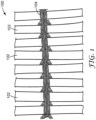
- FIG. 1 shows an exemplary hollow fiber membrane contactor component 100 in which a plurality of asymmetric hollow fiber membranes 102 is arranged substantially parallel in an array pattern and fastened together, in this case, by knitting or tying together the individual hollow fiber membranes 102 using string, thread, yarn, or the like 104.
- the present disclosure describes a separation article comprising a multiplicity of the asymmetric hollow fiber membranes according to any of the foregoing embodiments.
- the multiplicity of asymmetric hollow fiber membranes is arranged in an array.
- the array is pleated, folded, or rolled into a cylinder or a cassette.
- the separation article is selectively permeable to CO 2 over N 2 or CH 4 .
- the separation article exhibits a CO 2 /N 2 selectivity of at least 8, 9, 10, 11 or even 12.
- the filtration article is selectively permeable to O 2 over N 2 .
- the disclosure describes a method of using any of the foregoing separation articles, wherein the separation article is used to separate a gas phase from a liquid phase.
- the gas phase includes N 2 , O 2 , CO 2 , CH 4 , or a combination thereof.
- the gas phase includes water vapor.
- the separation article is selectively permeable to water vapor over air.
- the separation article may be useful in humidification or dehumidification of the gas phase.
- the gas phase includes one or more volatile organic compounds.
- the separation article may be useful in removing the volatile organic compounds from the gas phase.
- the liquid phase includes liquid water.
- the liquid phase is an aqueous printing ink, or an aqueous brine.
- the liquid phase includes one or more organic compounds.
- the liquid phase may contain one or more organic alcohol, ketone, ether, ester, or hydrocarbon solvent.
- the liquid phase may include one or more surfactants.
- the liquid phase may include one or more nonionic, anionic, cationic, or amphoteric surfactants.
- a hollow fiber membrane contactor typically includes a cylindrical bundle or mat of asymmetric hollow fibers, and a rigid cylindrical shell or housing enclosing the fiber bundle.
- the shell may be provided with multiple ports, for example, four fluid ports: an inlet for introducing the first fluid, an outlet for discharging the first fluid, an inlet for introducing the second fluid, and an outlet for discharging the second fluid.
- the hollow fibers may be potted on both ends, within the housing, to form polymeric tube sheets with the fiber bores opening on each end into first and second end cap portions of the shell.
- the number of windings or layers of hollow fiber array or fabric determines the depth of the panel.
- the end result is a hollow fiber array with X height, Y width, and Z depth.
- the hollow fiber array may be potted directly into a square or rectangular frame, similar in shape to an HVAC air filter.
- gas to be treated would pass through the contactor array on the shell side (outside of the hollow fibers) in a cross-flow pattern with liquid (hot, cold, humidifying, or absorbent liquid) passing through the lumen side (interior of the hollow fibers) of the contactor array.
- the present disclosure is directed to methods of producing or manufacturing asymmetric hollow fiber membrane contactors.
- the hollow fiber panel contactor is produced by a method including winding a hollow fiber membrane array around a paddle to form a square or rectangular format fiber bundle. The number of windings or layers determines the depth or thickness of the panel. The end result is a fiber array with X height, Y width, and Z depth. Then, the wound array is removed from the paddle and potted directly into a square or rectangular frame, similar in size and shape to a heating, ventilation and air conditioning (HVAC) air filter.
- HVAC heating, ventilation and air conditioning
- Such a panel contactor is adapted to have air pass through the array on the shell side (outside of hollow fibers) in a cross-flow pattern with liquid (hot, cold, humidifying, and/or absorbent liquid) passing through or vacuum applied to the lumen side (interior of the hollow fibers) of the contactor array.
- the panel contactor is produced by a method including pleating or folding (for example, z folded, accordion folded, or pleated, and then optionally wound) a hollow fiber membrane array to form a square or rectangular format fiber bundle.
- the number of folds or layers may determine the depth of the panel.
- the end result is a fiber array with X height, Y width, and Z depth.
- the folded or pleated array is potted into a square or rectangular frame, similar in shape to an HVAC air filter.
- Such a panel contactor is adapted to have air pass through the array on the shell side (outside of hollow fibers) in a cross-flow pattern with liquid (hot, cold, humidifying, and/or absorbent liquid) passing through or vacuum applied to the lumen side (interior of the hollow fibers) of the contactor array.
- the present disclosure is directed to methods of using or uses of flat panel hollow fiber array contactors.
- the panel contactor is used by a method including passing air to be treated through the contactor array on the shell side (outside of the hollow fibers) in a cross flow pattern at the same time that liquid (hot, cold, humidifying, and/or absorbent liquid) is passing through the lumen side (interior of the hollow fibers) of the contactor array.
- the contactor is a lumen-side liquid contactor.
- the panel contactor is used by or in a method including passing liquid to be treated through the contactor array on the shell side (outside of the hollow fibers) in a cross-flow pattern at the same time that a second liquid or gas is passing through the lumen side (interior of the hollow fibers) of the contactor array.
- the contactor is a shell-side liquid contactor.
- panel contactor may include: CO 2 scrubbing, greenhouse gas scrubbing, SO x scrubbing, NO x scrubbing, HCl scrubbing, ammonia scrubbing, gas humidification, gas dehumidification, absorption of moisture and latent heat for energy recovery in HVAC systems, air emission controls of noxious odors, such as at cattle or hog farms), and/or gas temperature control by varying the humidity level (such as in evaporative cooling or in a swamp cooler).
- the present new or improved hollow fiber membrane contactors address the drawbacks of prior contactors, are effective for some applications, are especially adapted for certain conditions, may have immediate customer familiarity and acceptance, do not use metal or other corrosive materials, do not use PVC, are modular, are replaceable, have standard air filter sizes, accommodate high air flow rates, have low shell-side pressure drop, allow for commercial production, and the like.
- a self-contained hollow fiber membrane contactor, filter or cartridge may include at least a first hollow fiber array including a plurality of at least first hollow fiber membranes each having a first end and a second end both being open, at least one rectangular frame, shell, casing or housing, and potting at each end.
- the first and second membrane ends are open, for example, to allow liquid to pass there through.
- the hollow fibers be polyolefin
- the frame be ABS
- the potting be made of epoxy, and that the ends of the potting be cut off to form the open first and second hollow fiber ends following potting.
- a combination or system of flat panel contactors includes two or more hollow fiber membrane panel contactors connected in series or in parallel.
- the combination or system of flat panel contactors includes two or more hollow fiber membrane panel contactors connected in series with the frames of adjacent contactors abutting and aligned with one another (an optional gasket can be placed between abutting frames and/or between the end frames and duct work to provide an air tight seal there between).
- the present panel membrane contactors preferably use thousands of asymmetric microporous hollow fibers knitted including into an array that is, for example, wound around a paddle or similar form, pleated, folded, and/or combinations thereof.
- the air to be treated flows over the shell side (outside) of the hollow fibers, while the liquid desiccant flows through or in the lumen side or lumen side (inside) of the hollow fibers.
- the membrane acts as an inert support to allow direct contact between a gas and liquid phase without dispersion.
- the typical applications include oxygen removal from boiler water, beverage carbonation, nitrogenation, and ink degassing.
- the system used for gassing/degassing is also known as membrane contactor.
- a gas-liquid interface is formed on the surface of microporous membrane due to fiber hydrophobicity and small pore size.
- Efficiency of a hollow fiber membrane contactor is largely determined by the membrane gas transfer rate, which depends on fiber permeability and available fiber surface area in the module.
- a typical hollow fiber membrane contactor consists of hundreds to thousands of asymmetric hollow fibers with at least 40% porosity. Smaller fiber diameters can allow a higher fiber packing density and provide higher total membrane surface area compared to a flat sheet membrane.
- the disclosure also describes methods of using any of the foregoing separation articles, in which the separation article is used to separate a gas phase from a liquid phase.
- the disclosure is directed to methods of using the asymmetric hollow fiber membrane contactors.
- Such asymmetric hollow fiber membrane contactors and/or use may address one or more of the above-described needs or drawbacks of conventional hollow fiber membranes.
- the gas phase includes N 2 , O 2 , CO 2 , CH 4 , or a combination thereof.
- the liquid phase includes liquid water.
- the liquid phase is an aqueous printing ink, or an aqueous brine (e.g., an aqueous well-injection brine used in petroleum recovery).
- a contactor system includes a source of liquid, a source of air or gas, and at least one flat panel contactor including a plurality of asymmetric hollow fibers, and a rectangular frame, shell, housing, or vessel.
- the source of liquid is preferably in fluid communication with the sheaths of the hollow fibers.
- the air or gas preferably passes over or across the fibers and through the contactor.
- An asymmetric hollow fiber membrane contactor may be used for many purposes, including but not limited to, removing entrained gases from liquids, de-gassing liquids, filtering liquids, and adding a gas to a liquid. More particularly, asymmetric hollow fiber membrane contactors may be used advantageously used in removing entrained gases from inks used in printing.
- asymmetric hollow fiber that includes a PDSP copolymer skin positioned on a porous polyolefin substrate .
- the thin nonporous skin layer prevents liquid breach-through while still maintaining substantial gas permeability.
- Asymmetric hollow fiber membrane contactors may also provide a means of accomplishing gas/gas, gas/liquid, and liquid/liquid (which can encompass liquid/dissolved solid) separations, transfers or additions.
- Membrane contactors typically are used to bring two immiscible fluid phases, for example, a first liquid and a second liquid, or a gas and a liquid, into contact with one another to effect separation and/or transfer of one or more components from one fluid to the other.
- the Gas Permeability Test is used as an integrity test for the non-porous skin layer as well as a performance test for the hollow fiber membranes.
- Loop modules were prepared by sealing hollow fibers together in a 1 ⁇ 4" OD nylon tube with DP100 epoxy adhesive. Fiber lumen were exposed by cutting the sealing tube with a razor blade after at least partially curing. Each loop module contained 10 fibers with 4" (about 10.2 cm) effective length.
- the Gas Permeability Test was conducted using a custom designed test stand.
- the stand was equipped with cylinders of pure gases (CO 2 and N 2 ), pressure gauges, and in-line gas flow meters.
- the principle of this testing is to supply a pure gas into fiber lumen and to measure the rate of the gas leaking through fiber walls into ambient environment. Both gas pressure and gas flow rate were monitored by a data acquisition software, and data are acquired when both pressure and gas flow are stabilized. Gas pressure in the fiber lumen was typically set at about 30 psi. Each fiber loop module was tested with CO 2 and N 2 , respectively.
- Gas permeation GPU Q ⁇ P ⁇ A ⁇ 10 6
- the fiber gas selectivity has been used as an indicator of skin integrity.
- the selectivity of PMP is typically in the range 11-13 according to a literature report ( Polymer, 1989, 30, 1357 ). Silicone gas selectivity is 10-12 ( Journal of Membrane Science, 1991, 55, 131 ). Any fiber with gas Selectivity below 8 was considered to have a defective skin.
- the hollow fiber membrane precursor was imbedded in Epoxy adhesive (DP 100 Plus) and cut into a short stub ( ⁇ 5 mm) after curing.
- Epoxy adhesive DP 100 Plus
- the imbedded precursor was visualized under optical microscopy (Carl Zeiss "AXIO” stereo microscope, Pleasanton, CA) to measure fiber OD, thicknesses of fiber wall and each layer.
- the fiber sample was fillet with a razor blade to expose its interior surface, followed by imaging by Phenom Desktop SEM (NanoScience Instruments Company, AZ).
- Dual-layer hollow fiber membrane precursors were co-extruded through a two-orifice annular ring die with a center air hole (custom designed coextruded die) using two Haake Single Screw Extruder, available from ThermoFisher Scientific (Grand Island, NY).
- the substrate resin was extruded through a central core of the die, and the skin layer resin was extruded through the annular ring of the die.
- the molten hollow fiber was solidified through a quench ring and collected by passing the hollow fiber membrane precursor through motor driven Godet rollers and winding on a tension-controlled spooler.
- Skin layer resin e.g., PDSP 15K
- porous substrate resin e.g., PPH 3721
- the porous substrate resin was extruded using a 3 ⁇ 4" (1.91 cm) extruder with 24 L/D, and the skin layer resin was extruded using a 1 ⁇ 2" (1.27 cm) extruder with a smaller output.
- a 3-zone porous substrate resin extruder was controlled at temperatures ranging from 200°C to 260°C from zone 1 to zone 3, while the 3-zone skin layer extruder was controlled at temperatures ranging from 220°C to 250°C for zones 1 to 3.
- the extrusion die temperature was set at 220°C-260°C.
- the two molten resin streams were metered through by pumps into a two-orifice die (custom designed co-extruded die) with a center air hole.
- the two molten streams converged inside the die at the location ⁇ 5 mm away from the die face.
- the orifices in the die were finetuned to maintain good concentricity to ensure the wall and layer uniformity of two-layer hollow fiber membranes.
- the extrusion rate of the skin layer resin was maintained significantly lower than the extrusion rate of the substrate resin in order to reduce the thickness of the skin layer.
- a low volume air flow was supplied in the center hole to prevent fibers from either collapsing or over blowing.
- the molten fibers were solidified by passing through an air quench ring.
- the hollow fiber membrane precursor diameter was controlled by drawing down with motordriven Godet rolls. The drawing speed was set in the range 50-100 meters per minute.
- the resultant hollow fiber membrane precursors were collected using a low-tension spooler.
- a 10" (25.4 cm) hollow fiber membrane precursor bundle was made with each end taped together using a high temperature tape.
- the bundle was annealed in a convection oven set at a temperature of 140°C-160°C.
- the annealing time for each fiber membrane precursor bundle was 10 min.
- Co-extruded hollow fiber membranes were made with PDSP (15K) as the skin material and PPH3271 as the porous substrate material (Example 1-3).
- PDSP is an AB diblock copolymer with silicone segments and a polyoxamide linkage.
- the silicone segment molecular weight of the PDSP 15K used in the examples is 15K Dalton.
- the PDSP/PP co-extruded hollow fiber membranes in Examples 1-6 were processed in the same way as the PMP/PMP co-extruded hollow fiber membranes of Comparative Example A, except that different materials were used for both the skin layer and the porous substrate and various process conditions were used.
- Example 1 the PP substrate was extruded at 260°C in both melt stream and extrusion die.
- the substrate melt stream had a similar processing temp as the skin melt stream.
- the PDSP/PP Co-extruded hollow fiber membrane gave excellent CO 2 gas flux (693GPU) while the CO 2 /N 2 selectivity is lower than 8, which was considered as the threshold number to indicate a good skin integrity.
- Example 2-3 PP substrate was extruded at 220°C in both melt stream and extrusion die while the substrate melt stream maintained at the same processing temp as one in Example 1.
- PDSP/PP co-extruded hollow fiber membrane precursor in Example 3 was wound in a faster speed than the precursor in Example 2.
- the resultant fiber membrane precursor in Example 3 is smaller in outside diameter as shown in Table 1.
- FIG. 4A shows the visual image of the hollow fiber membrane precursor in Example 2.
- the PDSP skin was uniformly located on top of the PPH3271 substrate.
- FIG. 4B provides a second image of the nonporous PDSP copolymer skin on a porous PPH3271 substrate after dry stretching the hollow fiber membrane precursor.
- the PDSP skin is substantially free from defects and pores.
- both PDSP/PP coextruded hollow fiber membranes after annealing and stretching resulted in both excellent CO 2 gas flux and good CO 2 /N 2 selectivity (>10).
- the membrane in Example 3 gave 784 GPU CO 2 gas flux, which is 21 times higher than the PMP/PMP coextruded hollow fiber membrane in Comparative Example A.
- Example 4-6 PP substrate was extruded at 260°C in melt stream with various substrate melt pump output but the co-extrusion die was controlled at 220°C. Processing conditions for the skin layer PDSP remained the same.
- Two interesting findings were observed from this set of experiments. First, controlling co-extrusion die temperature alone could improve dramatically CO 2 /N 2 gas selectivity of the coextruded hollow fiber membranes in Examples 4-6, compared to the membrane in Example 1. Second, no dramatic CO 2 gas flux change was seen with increasing substrate melt pump output. That implies the skin layer is the determining factor for gas fluxes of coextruded hollow fiber membranes.
- FIG. 2 is cross-section of the PDSP/PP coextruded hollow fiber membrane precursor.
- the oval shape of fiber membrane precursor was caused by sample preparation.
- This fiber membrane precursor shows PDSP layer thickness of 8.3um and the PP substrate layer 26.0um.
- Figure 4C is cross-section of the hollow fiber membrane after annealing and stretching.
- stretching co-extruded hollow fiber caused little substrate layer thickness change (28.9 ⁇ m).
- the skin layer had dramatical change in in thickness while remaining a solid dense film; its thickness changed from 8.3 ⁇ m to 2.6 ⁇ m.
- This skin thinning out is beneficial to improve membrane gas fluxes by controlling its thickness.
- the pore morphologies of the PP substrate layer were further confirmed by imaging the fiber interior surface ( Figure 4C ). A typical dry stretch membrane pore morphology is seen in the substrate layer including well oriented lamellae, and the micropores between by separated lamellae.
Landscapes
- Chemical & Material Sciences (AREA)
- Chemical Kinetics & Catalysis (AREA)
- Engineering & Computer Science (AREA)
- Manufacturing & Machinery (AREA)
- Physics & Mathematics (AREA)
- Thermal Sciences (AREA)
- Inorganic Chemistry (AREA)
- Analytical Chemistry (AREA)
- General Chemical & Material Sciences (AREA)
- Oil, Petroleum & Natural Gas (AREA)
- Separation Using Semi-Permeable Membranes (AREA)
- Manufacture Of Porous Articles, And Recovery And Treatment Of Waste Products (AREA)
Claims (15)
- Eine asymmetrische Hohlfasermembran, umfassend:ein poröses Substrat, das eine Vielzahl von Poren aufweist, wobei das poröse Substrat mindestens ein teilkristallines thermoplastisches Polyolefin(co)polymer umfasst; undeine Hautschicht, die das poröse Substrat überzieht, wobei die Hautschicht mindestens ein Polydiorganosiloxan-Polyoxamid-Copolymer umfasst, umfassend mindestens zwei Wiederholungseinheiten der Formel I:
 jedes R1 unabhängig ein Alkyl, Halogenalkyl, Aralkyl, Alkenyl, Aryl oder mit einem Alkyl, Alkoxy oder Halogen substituiertes Aryl ist;jedes Y unabhängig ein Alkylen, Aralkylen oder eine Kombination davon ist;G ein zweiwertiger Rest ist, der gleich einem Diamin der Formel R3HN-G-NHR3 minus den zwei -NHR3-Gruppen ist;R3 Wasserstoff oder Alkyl ist oder R3 zusammen mit G und mit dem Stickstoff, an den beide gebunden sind, eine heterocyclische Gruppe ausbildet;n unabhängig eine ganze Zahl von 0 bis 1500 ist;p eine ganze Zahl von 1 bis 10 ist; undq eine ganze Zahl von 1 oder größer ist, optional wobei n, p und q ausgewählt sind, so dass der Polydiorganosiloxanblock mindestens 50 Massenprozent des Polydiorganosiloxan-Polyoxamid-Copolymers umfasst.
 - Die asymmetrische Hohlfasermembran nach Anspruch 1, wobei mindestens 50 Prozent der R1-Gruppen Methyl sind, jedes Y ein Alkylen, aufweisend 1 bis 10 Kohlenstoffatome, Phenylen, das an ein Alkylen, aufweisend 1 bis 10 Kohlenstoffatome, gebunden ist, oder Phenylen ist, das an ein erstes Alkylen, aufweisend 1 bis 10 Kohlenstoffatome, und an ein zweites Alkylen, aufweisend 1 bis 10 Kohlenstoffatome, gebunden ist, n mindestens 40 ist, G ein Alkylen, Heteroalkylen, Arylen, Aralkylen, Polydiorganosiloxan oder eine Kombination davon ist und R3 H oder Methyl ist.
- Die asymmetrische Hohlfasermembran nach Anspruch 1, wobei das semikristalline thermoplastische Polyolefin(co)polymer durch Polymerisieren eines oder mehrerer verzweigter oder linearer Alpha-Olefinmonomere gewonnen wird, die aus der Gruppe ausgewählt sind, bestehend aus Ethylen, Propylen, 1-Buten, 1-Penten, 2-Methyl-1-penten, 3-Methyl-1-penten, 4-Methyl-1-penten, 1-Hexen, 1-Hepten, 1-Octen, 1-Nonen, 1-Decen, 1-Undecen, 1-Dodecen, 1-Tridecen, 1-Tetradecen, 1-Pentadecen, 1-Hexadecen, 1-Heptadecen, 1-Octadecen, 1-Eicosen oder einer Kombination davon.
- Die asymmetrische Hohlfasermembran nach Anspruch 1, wobei die Vielzahl von Poren eine Vielzahl von Mikroporen umfasst, wobei die Vielzahl von Mikroporen einen Durchmesser von 0,01 Mikrometer bis 1,0 Mikrometer aufweist, gemessen durch Rasterelektronenmikroskopie (SEM).
- Die asymmetrische Hohlfasermembran nach Anspruch 1, wobei die asymmetrische Hohlfasermembran eine Porosität von 5 % bis 80 % vorweist, gemessen durch Rasterelektronenmikroskopie (SEM).
- Die asymmetrische Hohlfasermembran nach Anspruch 1, wobei die Hautschicht weniger porös als das poröse Substrat ist und eine äußere Manteloberfläche der asymmetrischen Hohlfasermembran umfasst, optional wobei das poröse Substrat eine innere Lumenoberfläche der asymmetrischen Hohlfasermembran umfasst.
- Die asymmetrische Hohlfasermembran nach Anspruch 6, wobei die Hautschicht nicht porös ist.
- Die asymmetrische Hohlfasermembran nach Anspruch 1, wobei die Hautschicht eine Dicke von weniger als 20 Mikrometern aufweist.
- Die asymmetrische Hohlfasermembran nach Anspruch 1, wobei das poröse Substrat eine Dicke von 5 Mikrometern bis 200 Mikrometern aufweist.
- Ein Trennartikel, umfassend eine Vielzahl der asymmetrischen Hohlfasermembranen nach Anspruch 1.
- Der Trennartikel nach Anspruch 10, wobei die Vielzahl der asymmetrischen Hohlfasermembranen in einer Anordnung eingerichtet ist, optional wobei die Anordnung gefaltet, geknickt oder zu einem Zylinder oder einer Kassette gerollt ist.
- Der Trennartikel nach Anspruch 10, wobei der Trennartikel selektiv durchlässig für CO2 über N2, CO2 über CH4, Wasserdampf über Luft oder eine oder mehrere flüchtige organische Verbindungen über Luft ist.
- Der Trennartikel nach Anspruch 12, wobei der Trennartikel eine CO2/N2- oder CO2/CH4-Selektivität von mindestens 8, wie in der Beschreibung gemessen, vorweist.
- Ein Verfahren zum Herstellen einer asymmetrischen Hohlfasermembran, umfassend:Bereitstellen eines Substratharzes und eines Hautschichtharzes,wobei das Substratharz mindestens ein semikristallines thermoplastisches Polyolefin(co)polymer umfasst und das Hautschichtharz mindestens ein Polydiorganosiloxan-Polyoxamid-Copolymer umfasst, umfassend mindestens zwei Wiederholungseinheiten der Formel I:
 jedes R1 unabhängig ein Alkyl, Halogenalkyl, Aralkyl, Alkenyl, Aryl oder mit einem Alkyl, Alkoxy oder Halogen substituiertes Aryl ist;jedes Y unabhängig ein Alkylen, Aralkylen oder eine Kombination davon ist;G ein zweiwertiger Rest ist, der gleich einem Diamin der Formel R3HN-G-NHR3 minus den zwei -NHR3-Gruppen ist;R3 Wasserstoff oder Alkyl ist oder R3 zusammen mit G und mit dem Stickstoff, an den beide gebunden sind, eine heterocyclische Gruppe ausbildet;n unabhängig eine ganze Zahl von 0 bis 1500 ist;p eine ganze Zahl von 1 bis 10 ist; undq eine ganze Zahl von 1 oder größer ist, optional wobei n, p und q ausgewählt sind, so dass der Polydiorganosiloxanblock mindestens 50 Massenprozent des Polydiorganosiloxan-Polyoxamid-Copolymers umfasst;Coextrudieren des Substratharzes und des Hautschichtharzes, um einen Vorläufer der asymmetrischen Hohlfasermembran auszubilden; undStrecken des Vorläufers der asymmetrischen Hohlfasermembran, um eine asymmetrische Hohlfasermembran auszubilden, die eine im Wesentlichen nicht poröse Hautschicht aufweist, die aus dem Hautschichtharz besteht, das ein poröses Substrat überzieht, das aus dem Substratharz besteht, wobei das poröse Substrat eine Vielzahl von Poren umfasst.
 - Verfahren nach Anspruch 14, das ferner ein Tempern des Vorläufers der asymmetrischen Hohlfasermembran einschließt, optional wobei das Tempern des Vorläufers der asymmetrischen Hohlfasermembran das Tempern des Vorläufers der asymmetrischen Hohlfasermembran vor dem Strecken des Vorläufers der asymmetrischen Hohlfasermembran einschließt.
Applications Claiming Priority (2)
| Application Number | Priority Date | Filing Date | Title |
|---|---|---|---|
| US201962939987P | 2019-11-25 | 2019-11-25 | |
| PCT/IB2020/060996 WO2021105838A1 (en) | 2019-11-25 | 2020-11-21 | Hollow fiber membranes with polydiorganosiloxane polyoxamide copolymer skin layer and methods of making and using the same |
Publications (3)
| Publication Number | Publication Date |
|---|---|
| EP4065255A1 EP4065255A1 (de) | 2022-10-05 |
| EP4065255A4 EP4065255A4 (de) | 2024-01-10 |
| EP4065255B1 true EP4065255B1 (de) | 2025-04-23 |
Family
ID=76130063
Family Applications (1)
| Application Number | Title | Priority Date | Filing Date |
|---|---|---|---|
| EP20892856.4A Active EP4065255B1 (de) | 2019-11-25 | 2020-11-21 | Hohlfasermembranen mit polydiorganosiloxanpolyoxamid-copolymer-hautschicht und verfahren zu deren herstellung und verwendung |
Country Status (5)
| Country | Link |
|---|---|
| US (1) | US20220410078A1 (de) |
| EP (1) | EP4065255B1 (de) |
| JP (1) | JP7689523B2 (de) |
| CN (1) | CN114746166A (de) |
| WO (1) | WO2021105838A1 (de) |
Families Citing this family (1)
| Publication number | Priority date | Publication date | Assignee | Title |
|---|---|---|---|---|
| CN119923290A (zh) | 2022-09-09 | 2025-05-02 | 舒万诺知识产权公司 | 非对称中空纤维膜 |
Family Cites Families (30)
| Publication number | Priority date | Publication date | Assignee | Title |
|---|---|---|---|---|
| US3873653A (en) * | 1973-07-27 | 1975-03-25 | Us Interior | Preparation of high flux cellulose acetate membranes and hollow fibers from prefabricated low flux specimens |
| CA1151020A (en) * | 1980-05-01 | 1983-08-02 | Richard W. Baker | Reverse osmosis composite fiber membrane |
| JPH0712410B2 (ja) * | 1985-08-23 | 1995-02-15 | 大日本インキ化学工業株式会社 | 気体分離膜の製造方法 |
| US5006247A (en) * | 1989-08-15 | 1991-04-09 | Minnesota Mining And Manufacturing Company | Asymmetric porous polyamide membranes |
| JP2958030B2 (ja) * | 1989-10-25 | 1999-10-06 | 三菱レイヨン株式会社 | 有機溶剤混合液の分離方法 |
| US5096585A (en) * | 1991-01-28 | 1992-03-17 | W. R. Grace & Co.-Conn. | Process for preparing protein non-adsorptive microporous polysulfone membranes |
| US5181940A (en) * | 1991-08-01 | 1993-01-26 | Union Carbide Industrial Gases Technology Corporation | Hollow fiber membranes |
| TW408161B (en) * | 1997-04-30 | 2000-10-11 | Mitsubishi Rayon Co | Ink degassing hollow film, ink degassing method, ink degassing apparatus |
| WO2000043114A1 (de) * | 1999-01-21 | 2000-07-27 | Membrana Gmbh | Integral asymmetrische polyolefinmembran |
| EP1110596B1 (de) * | 1999-12-23 | 2004-07-07 | Membrana GmbH | Formkörper zur Pyrogenrückhaltung, Verfahren zu ihrer Herstellung und ihre Verwendung |
| US6599971B2 (en) * | 2001-03-29 | 2003-07-29 | Milliken & Company | Metals salts of hexahydrophthalic acid as nucleating additives for crystalline thermoplastics |
| US6616841B2 (en) | 2001-06-21 | 2003-09-09 | Celgard Inc. | Hollow fiber membrane contactor |
| US7501184B2 (en) | 2005-12-23 | 2009-03-10 | 3M Innovative Properties Company | Polydiorganosiloxane polyoxamide copolymers |
| WO2007075900A2 (en) * | 2005-12-23 | 2007-07-05 | 3M Innovative Properties Company | Multilayer films including thermoplastic silicone block copolymers |
| CN101346649B (zh) * | 2005-12-23 | 2010-09-01 | 3M创新有限公司 | 包含热塑性有机硅嵌段共聚物的膜 |
| US7371464B2 (en) * | 2005-12-23 | 2008-05-13 | 3M Innovative Properties Company | Adhesive compositions |
| US20080318065A1 (en) * | 2007-06-22 | 2008-12-25 | Sherman Audrey A | Mixtures of polydiorganosiloxane polyamide-containing components and organic polymers |
| JP2009095829A (ja) | 2007-09-28 | 2009-05-07 | Orion Mach Co Ltd | 水分離中空繊維および水分離フィルタ |
| DE102008041477A1 (de) * | 2008-08-22 | 2010-02-25 | Wacker Chemie Ag | Poröse Membranen aus Organopolysiloxan Copolymeren |
| WO2011039111A1 (en) * | 2009-09-30 | 2011-04-07 | Membrana Gmbh | Hollow fiber membrane mats with fluid impermeable segments and related methods |
| DE102013203129A1 (de) * | 2013-02-26 | 2014-08-28 | Wacker Chemie Ag | Asymmetrisch poröse Membranen aus vernetztem thermoplastischem Siliconelastomer |
| US20160228297A1 (en) * | 2013-10-04 | 2016-08-11 | 3M Innovative Properties Company | Multi-component fibers, nonwoven webs, and articles comprising a polydiorganosiloxane polyamide |
| JP2017515663A (ja) * | 2014-05-01 | 2017-06-15 | サビック グローバル テクノロジーズ ベスローテン フェンノートシャップ | スキンド非対称ポリ(フェニレンエーテル)共重合体膜、気体分離装置、及びこれらの作製方法 |
| US9480954B2 (en) * | 2015-03-18 | 2016-11-01 | Uop Llc | High selectivity epoxysilicone-cross-linked polyimide membranes for gas separations |
| GB201517272D0 (en) * | 2015-09-30 | 2015-11-11 | Norwegian Univ Sci & Tech Ntnu | Membrane contactor |
| EP3420018B1 (de) * | 2016-02-24 | 2019-12-25 | 3M Innovative Properties Company | Modifizierung von siloxan-polyoxamid-copolymeren mit ultraviolettem licht |
| US20190160436A1 (en) * | 2016-07-28 | 2019-05-30 | Honeywell International Inc. | Reverse osmosis membrane and method of processing the same |
| US11083992B2 (en) * | 2018-09-27 | 2021-08-10 | Uop Llc | Methods of making high selectivity facilitated transport membranes, high selectivity facilitated transport membrane elements and modules |
| KR20210107009A (ko) * | 2018-12-27 | 2021-08-31 | 쓰리엠 이노베이티브 프로퍼티즈 컴파니 | 핵화제를 갖는 중공 섬유 막 및 이의 제조 및 사용 방법 |
| WO2020136560A1 (en) * | 2018-12-27 | 2020-07-02 | 3M Innovative Properties Company | Asymmetric hollow fiber membranes and methods of making and using the same |
-
2020
- 2020-11-21 EP EP20892856.4A patent/EP4065255B1/de active Active
- 2020-11-21 US US17/756,338 patent/US20220410078A1/en active Pending
- 2020-11-21 JP JP2022530144A patent/JP7689523B2/ja active Active
- 2020-11-21 WO PCT/IB2020/060996 patent/WO2021105838A1/en not_active Ceased
- 2020-11-21 CN CN202080081772.6A patent/CN114746166A/zh not_active Withdrawn
Also Published As
| Publication number | Publication date |
|---|---|
| EP4065255A4 (de) | 2024-01-10 |
| US20220410078A1 (en) | 2022-12-29 |
| JP2023502768A (ja) | 2023-01-25 |
| WO2021105838A1 (en) | 2021-06-03 |
| JP7689523B2 (ja) | 2025-06-06 |
| EP4065255A1 (de) | 2022-10-05 |
| CN114746166A (zh) | 2022-07-12 |
Similar Documents
| Publication | Publication Date | Title |
|---|---|---|
| US11883777B2 (en) | Asymmetric hollow fiber membranes and methods of making and using the same | |
| US11986777B2 (en) | Hollow fiber membranes with nucleating agent and methods of making and using the same | |
| US10363546B2 (en) | Multilayer polymeric membrane | |
| DE69715112T2 (de) | Verwendung einer Polyhydrazidimidmembran zum Trennen von Luft | |
| EP1230970B1 (de) | Hitzebeständiger mikroporöser film | |
| US10946345B2 (en) | Microporous polyvinylidene fluoride membrane | |
| US20100058926A1 (en) | Photo-crosslinked gas selective membranes as part of thin film composite hollow fiber membranes | |
| CA2203051A1 (en) | Degassing liquids: apparatus and method | |
| JPWO2001028667A1 (ja) | 耐熱性微多孔膜 | |
| CN112657343A (zh) | 一种聚酰胺中空纤维复合分离膜及其制备方法 | |
| JP4987471B2 (ja) | フッ化ビニリデン系樹脂中空糸多孔濾水膜およびその製造方法 | |
| EP4065255B1 (de) | Hohlfasermembranen mit polydiorganosiloxanpolyoxamid-copolymer-hautschicht und verfahren zu deren herstellung und verwendung | |
| KR102573508B1 (ko) | 가스 분리막, 가스 분리막 엘리먼트, 및 가스 분리 방법 | |
| CN100571852C (zh) | 1,1-二氟乙烯系树脂中空丝多孔膜、使用它的水过滤方法及其制备方法 | |
| KR20180005879A (ko) | 역삼투막 | |
| EP2686089A1 (de) | Filtermembran auf polyolefinbasis und verfahren zur herstellung | |
| KR20180029418A (ko) | 역삼투막 및 이의 제조방법 | |
| JP2025529351A (ja) | 非対称中空繊維膜 | |
| DE102012001524A1 (de) | Verfahren zur Herstellung einer hydrophilen Polymermembran und Polymermembran |
Legal Events
| Date | Code | Title | Description |
|---|---|---|---|
| STAA | Information on the status of an ep patent application or granted ep patent |
Free format text: STATUS: THE INTERNATIONAL PUBLICATION HAS BEEN MADE |
|
| PUAI | Public reference made under article 153(3) epc to a published international application that has entered the european phase |
Free format text: ORIGINAL CODE: 0009012 |
|
| STAA | Information on the status of an ep patent application or granted ep patent |
Free format text: STATUS: REQUEST FOR EXAMINATION WAS MADE |
|
| 17P | Request for examination filed |
Effective date: 20220525 |
|
| AK | Designated contracting states |
Kind code of ref document: A1 Designated state(s): AL AT BE BG CH CY CZ DE DK EE ES FI FR GB GR HR HU IE IS IT LI LT LU LV MC MK MT NL NO PL PT RO RS SE SI SK SM TR |
|
| DAV | Request for validation of the european patent (deleted) | ||
| DAX | Request for extension of the european patent (deleted) | ||
| A4 | Supplementary search report drawn up and despatched |
Effective date: 20231207 |
|
| RIC1 | Information provided on ipc code assigned before grant |
Ipc: B01D 71/76 20060101ALI20231201BHEP Ipc: B01D 71/70 20060101ALI20231201BHEP Ipc: B01D 71/56 20060101ALI20231201BHEP Ipc: B01D 71/26 20060101ALI20231201BHEP Ipc: B01D 69/12 20060101ALI20231201BHEP Ipc: B01D 69/10 20060101ALI20231201BHEP Ipc: B01D 69/02 20060101ALI20231201BHEP Ipc: B01D 67/00 20060101ALI20231201BHEP Ipc: B01D 61/02 20060101AFI20231201BHEP |
|
| GRAP | Despatch of communication of intention to grant a patent |
Free format text: ORIGINAL CODE: EPIDOSNIGR1 |
|
| STAA | Information on the status of an ep patent application or granted ep patent |
Free format text: STATUS: GRANT OF PATENT IS INTENDED |
|
| INTG | Intention to grant announced |
Effective date: 20241125 |
|
| P01 | Opt-out of the competence of the unified patent court (upc) registered |
Free format text: CASE NUMBER: APP_2100/2025 Effective date: 20250113 |
|
| GRAS | Grant fee paid |
Free format text: ORIGINAL CODE: EPIDOSNIGR3 |
|
| GRAA | (expected) grant |
Free format text: ORIGINAL CODE: 0009210 |
|
| STAA | Information on the status of an ep patent application or granted ep patent |
Free format text: STATUS: THE PATENT HAS BEEN GRANTED |
|
| AK | Designated contracting states |
Kind code of ref document: B1 Designated state(s): AL AT BE BG CH CY CZ DE DK EE ES FI FR GB GR HR HU IE IS IT LI LT LU LV MC MK MT NL NO PL PT RO RS SE SI SK SM TR |
|
| REG | Reference to a national code |
Ref country code: GB Ref legal event code: FG4D |
|
| REG | Reference to a national code |
Ref country code: CH Ref legal event code: EP |
|
| REG | Reference to a national code |
Ref country code: DE Ref legal event code: R096 Ref document number: 602020050167 Country of ref document: DE |
|
| REG | Reference to a national code |
Ref country code: IE Ref legal event code: FG4D |
|
| REG | Reference to a national code |
Ref country code: NL Ref legal event code: MP Effective date: 20250423 |
|
| PG25 | Lapsed in a contracting state [announced via postgrant information from national office to epo] |
Ref country code: NL Free format text: LAPSE BECAUSE OF FAILURE TO SUBMIT A TRANSLATION OF THE DESCRIPTION OR TO PAY THE FEE WITHIN THE PRESCRIBED TIME-LIMIT Effective date: 20250423 |
|
| REG | Reference to a national code |
Ref country code: AT Ref legal event code: MK05 Ref document number: 1787283 Country of ref document: AT Kind code of ref document: T Effective date: 20250423 |
|
| PG25 | Lapsed in a contracting state [announced via postgrant information from national office to epo] |
Ref country code: FI Free format text: LAPSE BECAUSE OF FAILURE TO SUBMIT A TRANSLATION OF THE DESCRIPTION OR TO PAY THE FEE WITHIN THE PRESCRIBED TIME-LIMIT Effective date: 20250423 Ref country code: PT Free format text: LAPSE BECAUSE OF FAILURE TO SUBMIT A TRANSLATION OF THE DESCRIPTION OR TO PAY THE FEE WITHIN THE PRESCRIBED TIME-LIMIT Effective date: 20250825 Ref country code: ES Free format text: LAPSE BECAUSE OF FAILURE TO SUBMIT A TRANSLATION OF THE DESCRIPTION OR TO PAY THE FEE WITHIN THE PRESCRIBED TIME-LIMIT Effective date: 20250423 |
|
| REG | Reference to a national code |
Ref country code: LT Ref legal event code: MG9D |
|
| PG25 | Lapsed in a contracting state [announced via postgrant information from national office to epo] |
Ref country code: NO Free format text: LAPSE BECAUSE OF FAILURE TO SUBMIT A TRANSLATION OF THE DESCRIPTION OR TO PAY THE FEE WITHIN THE PRESCRIBED TIME-LIMIT Effective date: 20250723 Ref country code: GR Free format text: LAPSE BECAUSE OF FAILURE TO SUBMIT A TRANSLATION OF THE DESCRIPTION OR TO PAY THE FEE WITHIN THE PRESCRIBED TIME-LIMIT Effective date: 20250724 |
|
| PG25 | Lapsed in a contracting state [announced via postgrant information from national office to epo] |
Ref country code: PL Free format text: LAPSE BECAUSE OF FAILURE TO SUBMIT A TRANSLATION OF THE DESCRIPTION OR TO PAY THE FEE WITHIN THE PRESCRIBED TIME-LIMIT Effective date: 20250423 |
|
| PG25 | Lapsed in a contracting state [announced via postgrant information from national office to epo] |
Ref country code: BG Free format text: LAPSE BECAUSE OF FAILURE TO SUBMIT A TRANSLATION OF THE DESCRIPTION OR TO PAY THE FEE WITHIN THE PRESCRIBED TIME-LIMIT Effective date: 20250423 |
|
| PG25 | Lapsed in a contracting state [announced via postgrant information from national office to epo] |
Ref country code: HR Free format text: LAPSE BECAUSE OF FAILURE TO SUBMIT A TRANSLATION OF THE DESCRIPTION OR TO PAY THE FEE WITHIN THE PRESCRIBED TIME-LIMIT Effective date: 20250423 |
|
| PG25 | Lapsed in a contracting state [announced via postgrant information from national office to epo] |
Ref country code: AT Free format text: LAPSE BECAUSE OF FAILURE TO SUBMIT A TRANSLATION OF THE DESCRIPTION OR TO PAY THE FEE WITHIN THE PRESCRIBED TIME-LIMIT Effective date: 20250423 |
|
| PG25 | Lapsed in a contracting state [announced via postgrant information from national office to epo] |
Ref country code: RS Free format text: LAPSE BECAUSE OF FAILURE TO SUBMIT A TRANSLATION OF THE DESCRIPTION OR TO PAY THE FEE WITHIN THE PRESCRIBED TIME-LIMIT Effective date: 20250723 |
|
| PG25 | Lapsed in a contracting state [announced via postgrant information from national office to epo] |
Ref country code: IS Free format text: LAPSE BECAUSE OF FAILURE TO SUBMIT A TRANSLATION OF THE DESCRIPTION OR TO PAY THE FEE WITHIN THE PRESCRIBED TIME-LIMIT Effective date: 20250823 |
|
| PG25 | Lapsed in a contracting state [announced via postgrant information from national office to epo] |
Ref country code: LV Free format text: LAPSE BECAUSE OF FAILURE TO SUBMIT A TRANSLATION OF THE DESCRIPTION OR TO PAY THE FEE WITHIN THE PRESCRIBED TIME-LIMIT Effective date: 20250423 |
|
| PGFP | Annual fee paid to national office [announced via postgrant information from national office to epo] |
Ref country code: DE Payment date: 20251022 Year of fee payment: 6 |
|
| PG25 | Lapsed in a contracting state [announced via postgrant information from national office to epo] |
Ref country code: DK Free format text: LAPSE BECAUSE OF FAILURE TO SUBMIT A TRANSLATION OF THE DESCRIPTION OR TO PAY THE FEE WITHIN THE PRESCRIBED TIME-LIMIT Effective date: 20250423 Ref country code: SM Free format text: LAPSE BECAUSE OF FAILURE TO SUBMIT A TRANSLATION OF THE DESCRIPTION OR TO PAY THE FEE WITHIN THE PRESCRIBED TIME-LIMIT Effective date: 20250423 |
|
| PG25 | Lapsed in a contracting state [announced via postgrant information from national office to epo] |
Ref country code: CZ Free format text: LAPSE BECAUSE OF FAILURE TO SUBMIT A TRANSLATION OF THE DESCRIPTION OR TO PAY THE FEE WITHIN THE PRESCRIBED TIME-LIMIT Effective date: 20250423 |
|
| PG25 | Lapsed in a contracting state [announced via postgrant information from national office to epo] |
Ref country code: EE Free format text: LAPSE BECAUSE OF FAILURE TO SUBMIT A TRANSLATION OF THE DESCRIPTION OR TO PAY THE FEE WITHIN THE PRESCRIBED TIME-LIMIT Effective date: 20250423 |
|
| PG25 | Lapsed in a contracting state [announced via postgrant information from national office to epo] |
Ref country code: SK Free format text: LAPSE BECAUSE OF FAILURE TO SUBMIT A TRANSLATION OF THE DESCRIPTION OR TO PAY THE FEE WITHIN THE PRESCRIBED TIME-LIMIT Effective date: 20250423 |
|
| PG25 | Lapsed in a contracting state [announced via postgrant information from national office to epo] |
Ref country code: IT Free format text: LAPSE BECAUSE OF FAILURE TO SUBMIT A TRANSLATION OF THE DESCRIPTION OR TO PAY THE FEE WITHIN THE PRESCRIBED TIME-LIMIT Effective date: 20250423 |
|
| PG25 | Lapsed in a contracting state [announced via postgrant information from national office to epo] |
Ref country code: RO Free format text: LAPSE BECAUSE OF FAILURE TO SUBMIT A TRANSLATION OF THE DESCRIPTION OR TO PAY THE FEE WITHIN THE PRESCRIBED TIME-LIMIT Effective date: 20250423 |