EP4064412B1 - Batteriemanagementvorrichtung und -verfahren - Google Patents
Batteriemanagementvorrichtung und -verfahren Download PDFInfo
- Publication number
- EP4064412B1 EP4064412B1 EP21842626.0A EP21842626A EP4064412B1 EP 4064412 B1 EP4064412 B1 EP 4064412B1 EP 21842626 A EP21842626 A EP 21842626A EP 4064412 B1 EP4064412 B1 EP 4064412B1
- Authority
- EP
- European Patent Office
- Prior art keywords
- capacity
- peak
- voltage
- battery
- differential
- Prior art date
- Legal status (The legal status is an assumption and is not a legal conclusion. Google has not performed a legal analysis and makes no representation as to the accuracy of the status listed.)
- Active
Links
Images


Classifications
-
- H—ELECTRICITY
- H01—ELECTRIC ELEMENTS
- H01M—PROCESSES OR MEANS, e.g. BATTERIES, FOR THE DIRECT CONVERSION OF CHEMICAL ENERGY INTO ELECTRICAL ENERGY
- H01M10/00—Secondary cells; Manufacture thereof
- H01M10/42—Methods or arrangements for servicing or maintenance of secondary cells or secondary half-cells
- H01M10/44—Methods for charging or discharging
-
- G—PHYSICS
- G01—MEASURING; TESTING
- G01R—MEASURING ELECTRIC VARIABLES; MEASURING MAGNETIC VARIABLES
- G01R19/00—Arrangements for measuring currents or voltages or for indicating presence or sign thereof
- G01R19/165—Indicating that current or voltage is either above or below a predetermined value or within or outside a predetermined range of values
- G01R19/16528—Indicating that current or voltage is either above or below a predetermined value or within or outside a predetermined range of values using digital techniques or performing arithmetic operations
-
- G—PHYSICS
- G01—MEASURING; TESTING
- G01R—MEASURING ELECTRIC VARIABLES; MEASURING MAGNETIC VARIABLES
- G01R31/00—Arrangements for testing electric properties; Arrangements for locating electric faults; Arrangements for electrical testing characterised by what is being tested not provided for elsewhere
- G01R31/36—Arrangements for testing, measuring or monitoring the electrical condition of accumulators or electric batteries, e.g. capacity or state of charge [SoC]
- G01R31/3644—Constructional arrangements
- G01R31/3648—Constructional arrangements comprising digital calculation means, e.g. for performing an algorithm
-
- G—PHYSICS
- G01—MEASURING; TESTING
- G01R—MEASURING ELECTRIC VARIABLES; MEASURING MAGNETIC VARIABLES
- G01R31/00—Arrangements for testing electric properties; Arrangements for locating electric faults; Arrangements for electrical testing characterised by what is being tested not provided for elsewhere
- G01R31/36—Arrangements for testing, measuring or monitoring the electrical condition of accumulators or electric batteries, e.g. capacity or state of charge [SoC]
- G01R31/367—Software therefor, e.g. for battery testing using modelling or look-up tables
-
- G—PHYSICS
- G01—MEASURING; TESTING
- G01R—MEASURING ELECTRIC VARIABLES; MEASURING MAGNETIC VARIABLES
- G01R31/00—Arrangements for testing electric properties; Arrangements for locating electric faults; Arrangements for electrical testing characterised by what is being tested not provided for elsewhere
- G01R31/36—Arrangements for testing, measuring or monitoring the electrical condition of accumulators or electric batteries, e.g. capacity or state of charge [SoC]
- G01R31/382—Arrangements for monitoring battery or accumulator variables, e.g. SoC
- G01R31/3835—Arrangements for monitoring battery or accumulator variables, e.g. SoC involving only voltage measurements
-
- G—PHYSICS
- G01—MEASURING; TESTING
- G01R—MEASURING ELECTRIC VARIABLES; MEASURING MAGNETIC VARIABLES
- G01R31/00—Arrangements for testing electric properties; Arrangements for locating electric faults; Arrangements for electrical testing characterised by what is being tested not provided for elsewhere
- G01R31/36—Arrangements for testing, measuring or monitoring the electrical condition of accumulators or electric batteries, e.g. capacity or state of charge [SoC]
- G01R31/396—Acquisition or processing of data for testing or for monitoring individual cells or groups of cells within a battery
-
- H—ELECTRICITY
- H01—ELECTRIC ELEMENTS
- H01M—PROCESSES OR MEANS, e.g. BATTERIES, FOR THE DIRECT CONVERSION OF CHEMICAL ENERGY INTO ELECTRICAL ENERGY
- H01M10/00—Secondary cells; Manufacture thereof
- H01M10/05—Accumulators with non-aqueous electrolyte
- H01M10/052—Li-accumulators
-
- H—ELECTRICITY
- H01—ELECTRIC ELEMENTS
- H01M—PROCESSES OR MEANS, e.g. BATTERIES, FOR THE DIRECT CONVERSION OF CHEMICAL ENERGY INTO ELECTRICAL ENERGY
- H01M10/00—Secondary cells; Manufacture thereof
- H01M10/42—Methods or arrangements for servicing or maintenance of secondary cells or secondary half-cells
- H01M10/425—Structural combination with electronic components, e.g. electronic circuits integrated to the outside of the casing
-
- H—ELECTRICITY
- H01—ELECTRIC ELEMENTS
- H01M—PROCESSES OR MEANS, e.g. BATTERIES, FOR THE DIRECT CONVERSION OF CHEMICAL ENERGY INTO ELECTRICAL ENERGY
- H01M10/00—Secondary cells; Manufacture thereof
- H01M10/42—Methods or arrangements for servicing or maintenance of secondary cells or secondary half-cells
- H01M10/48—Accumulators combined with arrangements for measuring, testing or indicating the condition of cells, e.g. the level or density of the electrolyte
-
- H—ELECTRICITY
- H01—ELECTRIC ELEMENTS
- H01M—PROCESSES OR MEANS, e.g. BATTERIES, FOR THE DIRECT CONVERSION OF CHEMICAL ENERGY INTO ELECTRICAL ENERGY
- H01M4/00—Electrodes
- H01M4/02—Electrodes composed of, or comprising, active material
- H01M4/36—Selection of substances as active materials, active masses, active liquids
- H01M4/48—Selection of substances as active materials, active masses, active liquids of inorganic oxides or hydroxides
- H01M4/52—Selection of substances as active materials, active masses, active liquids of inorganic oxides or hydroxides of nickel, cobalt or iron
- H01M4/525—Selection of substances as active materials, active masses, active liquids of inorganic oxides or hydroxides of nickel, cobalt or iron of mixed oxides or hydroxides containing iron, cobalt or nickel for inserting or intercalating light metals, e.g. LiNiO2, LiCoO2 or LiCoOxFy
-
- H—ELECTRICITY
- H01—ELECTRIC ELEMENTS
- H01M—PROCESSES OR MEANS, e.g. BATTERIES, FOR THE DIRECT CONVERSION OF CHEMICAL ENERGY INTO ELECTRICAL ENERGY
- H01M10/00—Secondary cells; Manufacture thereof
- H01M10/42—Methods or arrangements for servicing or maintenance of secondary cells or secondary half-cells
- H01M10/425—Structural combination with electronic components, e.g. electronic circuits integrated to the outside of the casing
- H01M2010/4271—Battery management systems including electronic circuits, e.g. control of current or voltage to keep battery in healthy state, cell balancing
-
- Y—GENERAL TAGGING OF NEW TECHNOLOGICAL DEVELOPMENTS; GENERAL TAGGING OF CROSS-SECTIONAL TECHNOLOGIES SPANNING OVER SEVERAL SECTIONS OF THE IPC; TECHNICAL SUBJECTS COVERED BY FORMER USPC CROSS-REFERENCE ART COLLECTIONS [XRACs] AND DIGESTS
- Y02—TECHNOLOGIES OR APPLICATIONS FOR MITIGATION OR ADAPTATION AGAINST CLIMATE CHANGE
- Y02E—REDUCTION OF GREENHOUSE GAS [GHG] EMISSIONS, RELATED TO ENERGY GENERATION, TRANSMISSION OR DISTRIBUTION
- Y02E60/00—Enabling technologies; Technologies with a potential or indirect contribution to GHG emissions mitigation
- Y02E60/10—Energy storage using batteries
Definitions
- the present disclosure relates to a battery management apparatus and method, and more particularly, to a battery management apparatus and method for determining a state of a battery from various aspects based on a differential profile for the battery.
- Batteries commercially available at present include nickel-cadmium batteries, nickel hydrogen batteries, nickel-zinc batteries, lithium batteries and the like.
- the lithium batteries are in the limelight since they have almost no memory effect compared to nickel-based batteries and also have very low self-charging rate and high energy density.
- the battery may be degraded as charging or discharging is repeated.
- the battery may be degraded as the electrolyte is oxidized or the crystal structure is destroyed.
- the battery may be degraded since metallic lithium is precipitated.
- the degradation of the battery is diagnosed based on a battery profile obtained in the process of charging the battery.
- the state of the battery is diagnosed based on the behavior of a peak included in a differential profile of the battery.
- the state of the battery is diagnosed using a charging profile (a profile obtained in the charging process) or a discharging profile (a profile obtained in the discharging process), or it is limitedly diagnosed whether the positive electrode of the battery is degraded or the negative electrode is degraded for each peak.
- CN110927607A , CN110888079A , CN110045293A and US2017/139014A1 each relate to devices for identifying the decline of a Li-ion battery.
- the present disclosure is designed to solve the problems of the related art, and therefore the present disclosure is directed to providing a battery management apparatus and method, which determines a state of a battery from various aspects based on the behavior of a peak included in a differential profile for the battery.
- a battery management apparatus according to claim 1 is provided in one aspect of the present disclosure.
- the control unit may be configured to determine at least one of whether positive electrode capacity of the battery is lost and whether the available lithium of the battery is lost based on the behavior change of the target peak with respect to the reference peak, when the received differential profile is a differential capacity profile representing the correspondence between the differential capacity and the voltage.
- the control unit may be configured to set a capacity range from a discharge end capacity of the battery to a capacity symmetrical to the discharge end capacity of the battery based on the capacity of the reference voltage peak as the target capacity range.
- the control unit may be configured to determine that available lithium of the battery is lost, when the number of the determined target voltage peak is one and the differential voltage of the target voltage peak decreases compared to the differential voltage of the reference voltage peak.
- the control unit may be configured to determine that available lithium of the battery is lost, when the number of the determined target voltage peak is two or more.
- the control unit may be configured to set a voltage range from a preset voltage to a charge end voltage preset for the battery in the entire voltage range of the differential capacity profile as a target voltage range, determine a peak included in the target voltage range of the differential capacity profile as a target capacity peak, and determine at least one of whether the positive electrode capacity is lost and whether the available lithium is lost based on the target capacity peak and a reference capacity peak preset to correspond to the target capacity peak.
- the control unit may be configured to set a peak included in the target voltage range of a reference capacity profile preset to correspond to the differential capacity profile as the reference capacity peak.
- the control unit may be configured to determine whether the positive electrode capacity of the battery is lost according to a result of comparing the differential capacity of the reference capacity peak and the differential capacity of the target capacity peak, and determine whether the available lithium of the battery is lost according to a result of comparing the differential capacity and the voltage of the reference capacity peak and the differential capacity and the voltage of the target capacity peak, respectively.
- the control unit may be configured to determine that available lithium of the battery is lost, when the differential capacity of the target capacity peak increases compared to the differential capacity of the reference capacity peak and the voltage of the target capacity peak decreases compared to the voltage of the reference capacity peak.
- the control unit may be configured to determine that positive electrode capacity of the battery is lost, when the differential capacity of the target capacity peak decreases compared to the differential capacity of the reference capacity peak.
- the control unit may be configured to change at least one of a threshold value of a charging C-rate and a threshold value of a discharging C-rate preset for the battery, when it is determine that the positive electrode capacity or the available lithium of the battery is lost.
- a battery pack according to another aspect of the present disclosure may comprise the battery management apparatus according to an aspect of the present disclosure.
- a battery management method according to claim 13 is provided according to another aspect of the present disclosure.
- the state of the battery may be determined from more various aspects. That is, according to one aspect of the present disclosure, there is an advantage in that a new analysis method for a differential profile of a battery is proposed.
- control unit refers to a unit that processes at least one function or operation, and may be implemented by hardware, software, or a combination of hardware and software.
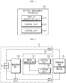
- FIG. 1 is a diagram schematically showing a battery management apparatus 100 according to an embodiment of the present disclosure.
- FIG. 2 is a diagram showing an exemplary configuration of a battery pack 10 including the battery management apparatus 100 according to an embodiment of the present disclosure.
- the battery management apparatus 100 may include a profile generating unit 110 and a control unit 120.
- the profile generating unit 110 may be configured to obtain a battery profile representing a correspondence between voltage and capacity of a battery B.
- the battery B means one independent cell that includes a negative electrode terminal and a positive electrode terminal and is physically separable.
- one lithium-ion cell or lithium polymer cell may be regarded as the battery B.
- the battery profile may be configured to represent a correspondence between voltage and capacity of the battery B that is measured while the battery B is being charged or discharged. That is, the profile generating unit 110 may obtain a battery profile for voltage and capacity measured while the battery B is being charged or discharged.
- FIG. 3 is a diagram schematically showing a battery profile, a positive electrode profile, and a negative electrode profile according to an embodiment of the present disclosure. Specifically, FIG. 3 is a diagram showing a battery profile, a positive electrode profile, and a negative electrode profile as a graph showing a correspondence between capacity and voltage.
- the battery profile may be configured to represent a correspondence between voltage and capacity of a battery B measured in the process of charging or discharging the battery B at a C-rate of 1 C or less. More preferably, the battery profile may be configured to represent a correspondence between the voltage and capacity of the battery B measured while the battery B is being charged or discharged at a C-rate of 0.05 C.
- the battery B may be charged or discharged by a charging and discharging device 20.
- a measuring unit 200 may measure the voltage of the battery B through a plurality of sensing lines connected to the battery B.
- the measuring unit 200 may measure the capacity of the battery B using a current measuring unit A.
- the unit of voltage may be [V]
- the unit of capacity (Q) may be [mAh].
- the measuring unit 200 may generate a battery profile representing the correspondence between the voltage and capacity of the battery B measured at the same time point, and transmit the generated battery profile to the profile generating unit 110.
- the battery profile may be a table in which a voltage value and a capacity value measured at the same time point are mapped.
- the profile generating unit 110 may be configured to generate a differential profile representing a correspondence between a differential voltage for the capacity of the battery B and the capacity or a correspondence between a differential capacity for the voltage of the battery B and the voltage based on the obtained battery profile.
- the differential voltage is obtained by differentiating voltage with respect to capacity, and may be expressed as "dV/dQ", and the unit may be [V/mAh].
- the differential voltage profile may be expressed as an X-Y graph when X is set as capacity and Y is set as differential voltage.
- the differential capacity is obtained by differentiating capacity with respect to voltage, and may be expressed as "dQ/dV", and the unit may be [mAh/V].
- the differential capacity profile may be expressed as an X-Y graph when X is set as voltage and Y is set as differential capacity.
- the profile generating unit 110 may convert the obtained battery profile into a differential voltage profile.
- the profile generating unit 110 may extract voltage and capacity from the battery profile, and calculate a differential voltage (dV/dQ) for the capacity (Q).
- the profile generating unit 110 may generate a differential voltage profile representing a correspondence between the capacity (Q) of the battery B and the differential voltage (dV/dQ).
- the profile generating unit 110 may convert the obtained battery profile into a differential capacity profile.
- the profile generating unit 110 may extract voltage and capacity from the battery profile, and calculate a differential capacity (dQ/dV) for the voltage (V).
- the profile generating unit 110 may generate a differential capacity profile representing a correspondence between the voltage of the battery B and the differential capacity (dQ/dV).
- the control unit 120 may be configured to receive the generated differential profile from the profile generating unit 110.
- control unit 120 and the profile generating unit 110 may be connected to each other to enable communication.
- control unit 120 and the profile generating unit 110 may be connected to each other, and the profile generating unit 110 may transmit the generated differential profile to the control unit 120.
- the control unit 120 may be configured to determine a target peak included in the received differential profile according to a rule corresponding to the type of the received differential profile.
- the control unit 120 may determine a peak included in a target capacity range of the differential voltage profile as the target peak.
- the control unit 120 may determine a peak included in the target voltage range of the differential capacity profile as the target peak.
- the target peak determined in the differential voltage profile and the differential capacity profile will be described below in detail with reference to FIGS. 4 to 9 .
- the control unit 120 may be configured to determine the state of the battery B based on a behavior change of the target peak with respect to a reference peak preset to correspond to the type of the received differential profile.
- the reference peak may be set to correspond to the type of the differential profile, respectively. That is, the reference peak configured to correspond to the differential voltage profile and the reference peak configured to correspond to the differential capacity profile may be different from each other.
- control unit 120 may be configured to determine whether available lithium of the battery B is lost based on the behavior change of the target peak with respect to the reference peak.
- control unit 120 may be configured to determine at least one of whether positive electrode capacity of the battery B is lost and whether the available lithium is lost based on the behavior change of the target peak with respect to the reference peak.
- the state of the battery B since it may be determined whether the positive electrode capacity is lost and/or whether the available lithium is lost based on the behavior change of the target peak with respect to the reference peak, there is an advantage in that the state of the battery B may be determined in more various aspects.
- control unit 120 provided to the battery management apparatus 100 may selectively include processors known in the art, application-specific integrated circuit (ASIC), other chipsets, logic circuits, registers, communication modems, data processing devices, and the like to execute various control logic performed in the present disclosure.
- ASIC application-specific integrated circuit
- the control unit 120 may be implemented as a set of program modules.
- the program module may be stored in a memory and executed by the control unit 120.
- the memory may be located inside or out of the control unit 120 and may be connected to the control unit 120 by various well-known means.
- the battery management apparatus 100 may further include a storage unit 130.
- the storage unit 130 may store program, data, and the like required by the control unit 120. That is, the storage unit 130 may store data necessary for operation and function of each component of the battery management apparatus 100 according to an embodiment of the present disclosure, data generated in the process of performing the operation or function, or the like.
- the storage unit 130 is not particularly limited in its kind as long as it is a known information storage means that can record, erase, update and read data.
- the information storage means may include RAM, flash memory, ROM, EEPROM, registers, and the like.
- the storage unit 130 may store program codes in which processes executable by the control unit 120 are defined.
- the storage unit 130 may be connected to the profile generating unit 110 and the control unit 120, respectively.
- the storage unit 130 may store the differential profile generated by the profile generating unit 110.
- the control unit 120 may receive the differential profile directly from the profile generating unit 110, or may access the storage unit 130 to obtain the differential profile.
- control unit 120 determines the state of the battery B based on the differential voltage profile.
- target peak corresponding to the differential voltage profile will be described as a target voltage peak
- reference peak will be described as a reference voltage peak.
- control unit 120 determines whether available lithium of the battery B is lost based on the target voltage peak and the reference voltage peak will be described in detail.
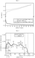
- FIG. 4 is a diagram schematically showing a first reference voltage profile (R_dVdQ_P1) and a first differential voltage profile (dVdQ_P1) according to an embodiment of the present disclosure.
- FIG. 4 is a diagram illustrating a first reference voltage profile (R_dVdQ_P1) for a battery B in a beginning of life (BoL) state and a first differential voltage profile (dVdQ_P1) for a battery B in which available lithium is lost.
- the profile generating unit 110 may generate a first differential voltage profile (dVdQ_P1) representing the correspondence between the capacity (Q) of the battery B and the differential voltage (dV/dQ).
- dVdQ_P1 a first differential voltage profile representing the correspondence between the capacity (Q) of the battery B and the differential voltage (dV/dQ).
- the control unit 120 may be configured to set a target capacity range based on the capacity of the reference voltage peak corresponding to the differential voltage profile in the entire capacity range of the differential voltage profile. That is, the control unit 120 may set the target capacity range among the entire capacity range of the differential voltage profile based on the capacity of the reference voltage peak.
- the target capacity range may be set based on the capacity of a preset reference voltage peak.
- the target capacity range may be preset and input to the control unit 120 or may be directly set by the control unit 120.
- the target capacity range (QR1) may be set to a range of 0 [mAh] or more and K4 [mAh] or less.
- the control unit 120 sets the target capacity range (QR1) will be described later.
- the control unit 120 may be configured to determine a peak included in the target capacity range of the differential voltage profile as a target voltage peak.
- control unit 120 may be configured to determine a plurality of peaks from the received differential voltage profile.
- control unit 120 may calculate an instantaneous change rate of the differential voltage with respect to the capacity from the received differential voltage profile.
- the control unit 120 may determine a point where the instantaneous change rate of the differential voltage for the capacity at a low capacity side is positive among points where the calculated instantaneous change rate is 0 and the instantaneous change rate of the differential voltage for the capacity at a high capacity side is negative as a peak. That is, the control unit 120 may determine an upward convex point in the differential voltage profile as a peak.
- the control unit 120 may determine a plurality of peaks P1, P2, P3, P4, P5 in the first differential voltage profile (dVdQ_P1).
- the plurality of peaks P1, P2, P3, P4, P5 are points at which the instantaneous change rate of the differential voltage for the capacity is 0. Based on the corresponding peaks, the instantaneous change rate of the differential voltage for the capacity at the low-capacity side may be positive, and the instantaneous change rate of the differential voltage for the capacity at the high-capacity side may be negative.
- control unit 120 may determine the peak P1 and the peak P2 included in the target capacity range (QR1) among the plurality of peaks P1, P2, P3, P4, P5 in the first differential voltage profile (dVdQ_P1) as a target voltage peak (TV1).
- control unit 120 may be configured to determine a behavior change of the target voltage peak with respect to the reference voltage peak.
- the reference voltage peak may be preset as a peak whose corresponding capacity is smallest in a reference voltage profile preset to correspond to the differential voltage profile.
- the reference voltage peak may be preset and input to the control unit 120, or the control unit 120 may set a peak whose corresponding capacity is smallest among a plurality of peaks included in the reference voltage profile as the reference voltage peak.
- the reference voltage peak may be set by the control unit 120.
- the reference voltage profile may be a differential profile generated in the process of discharging a reference cell.
- the reference cell is a cell corresponding to the battery B, and may be a battery B in a BoL state or a battery separately manufactured to generate the reference voltage profile.
- the reference cell will be described as a battery B in a BoL state.
- the reference voltage profile may be a differential voltage profile obtained based on the voltage and capacity of the reference cell measured while the reference cell is discharged at a C-rate of 1 C or less. More preferably, the reference voltage profile may be a differential voltage profile obtained based on the voltage and capacity of the reference cell measured while the reference cell is discharged at a C-rate of 0.05 C.
- the first reference voltage profile (R_dVdQ_P1) may include a plurality of peaks R1, R2, R3, R4, R5, R6, and R7.
- the peak R1 having the smallest corresponding capacity among the plurality of peaks R1, R2, R3, R4, R5, R6, and R7 may be set as the reference voltage peak (RV1).
- the capacity of the reference voltage peak (RV1) may be K2 [mAh].
- the control unit 120 may be configured to determine whether the available lithium is lost based on the reference voltage peak and the target voltage peak.
- control unit 120 may be configured to diagnose whether available lithium included in the battery B is lost based on the behavior change of the target voltage peak with respect to the reference voltage peak.
- control unit 120 may be configured to diagnose that the available lithium of the battery is lost when the number of the determined target voltage peak is two or more.
- the target capacity range (QR1) of the first differential voltage profile (dVdQ_P1) may include a peak P1 and a peak P2. That is, the peak P1 and a peak P2 may be the target voltage peak (TV1). In this case, since the number of target voltage peaks TV1 is plural, the control unit 120 may diagnose the state of the battery B as an available lithium loss state.
- FIG. 5 is a diagram schematically showing a second reference voltage profile (R_dVdQ_P2) and a second differential voltage profile (dVdQ_P2) according to an embodiment of the present disclosure.
- FIG. 5 is a diagram illustrating a second reference voltage profile (R_dVdQ_P2) for a battery B in a BoL state and a second differential voltage profile (dVdQ_P2) for a battery B in which available lithium is lost.
- the battery B according to the embodiment of FIG. 4 and the battery B according to the embodiment of FIG. 5 may be different from each other.
- the reference signs of the battery B according to the embodiment of FIG. 4 and the battery B according to the embodiment of FIG. 5 are identically described as "B".
- the second reference voltage profile (R_dVdQ_P2) may include a plurality of peaks R1, R2, R3, R4, R5, R6, R7, R8.
- the peak R1 whose corresponding capacity is smallest among the plurality of peaks R1, R2, R3, R4, R5, R6, R7, R8 included in the second reference voltage profile (R_dVdQ_P2) may be set as the reference voltage peak (RV2).
- the capacity of the reference voltage peak (RV2) may be X2 [mAh].
- the second differential voltage profile (dVdQ_P2) may include a plurality of peaks P1, P2, P3, P4, P5, P6, P7.
- the control unit 120 sets the target capacity range (QR2) of the second differential voltage profile (dVdQ_P2) as a capacity range of 0 [mAh] or more and X3 [mAh] or less, and sets the peak P1 included in the target capacity range (QR2) as the target voltage peak (TV2).
- the control unit 120 may be configured to diagnose that the available lithium is lost when the number of the determined target voltage peak is one and the differential voltage of the target voltage peak is lower than the differential voltage of the reference voltage peak.
- the control unit 120 may compare the differential voltages of the target voltage peak (TV2) and the reference voltage peak (RV2).
- the differential voltage of the target voltage peak (TV2) is Y1
- the differential voltage of the reference voltage peak (RV2) is Y2. That is, since the differential voltage (Y1) of the target voltage peak (TV2) is smaller than the differential voltage (Y2) of the reference voltage peak (RV2), the control unit 120 may diagnose the state of the battery B as an available lithium loss state.
- the control unit 120 may diagnose the state of the battery B as an available lithium loss state. In addition, the control unit 120 may also diagnose the state of the battery B as an available lithium loss state even when the number of target voltage peaks included in the differential voltage profile is one and the differential voltage of the target voltage peak is smaller than the differential voltage of the reference voltage peak.
- the battery management apparatus 100 has an advantage of determining the behavior change of the target voltage peak with respect to the reference voltage peak and specifically diagnosing whether the available lithium of the battery B is lost as a result of the determination. That is, the battery management apparatus 100 has an advantage in that the cause of degradation of the battery B may be specifically diagnosed as the available lithium loss.
- control unit 120 may be configured to set a capacity range in which the capacity of the reference voltage peak is an intermediate value as the target capacity range.
- control unit 120 may be configured to set a capacity range from the discharge end capacity (EoD) of the battery B to a capacity symmetrical to the discharge end capacity (EoD) based on the capacity of the reference voltage peak as the target capacity range.
- the discharge end capacity (EoD) may be "0 [mAh]”
- the capacity of the reference voltage peak (RV1) may be "K2 [mAh]”.
- K4 [mAh] may be "2 ⁇ K2 [mAh]”.
- the target capacity range (QR1) may be set to a capacity range of 0 [mAh] or more and K4 [mAh] or less.
- the discharge end capacity (EoD) may be "0 [mAh]", and the capacity of the reference voltage peak (RV2) may be “X2 [mAh]”. Also, X3 [mAh] may be "2 ⁇ X2 [mAh]”. Accordingly, the target capacity range (QR2) may be set to a capacity range of 0 [mAh] or more and X3 [mAh] or less.
- phase equilibrium may occur several times while the battery B is charged or discharged.
- a peak may appear in the differential profile of the battery B. That is, the phase equilibrium generated inside the battery may be expressed in the form of a peak in the differential profile of the battery B.
- the reference voltage peak may be set as a peak corresponding to the phase equilibrium occurring at the lowest capacity among a plurality of phase equilibriums that may be generated in the process of discharging the battery B. That is, the reference voltage peak may be set as a peak corresponding to the last phase equilibrium occurring at the discharging end.
- the control unit 120 may set a capacity range up to a capacity symmetrical to the discharge end capacity (EoD) based on the capacity of the reference voltage peak as the target capacity range.
- the last phase equilibrium of the reference cell may occur at K2 [mAh], and due to the phase equilibrium, the peak R1 shown in the first reference voltage profile (R_dVdQ_P1) may be set as the reference voltage peak (RV1).
- the target capacity range (QR1) may be set to a capacity range of 0 [mAh] or more and K4 [mAh] or less.
- the final phase equilibrium of the reference cell may occur at X2 [mAh], and the peak R1 shown in the second reference voltage profile (R_dVdQ_P2) due to the phase equilibrium may be set as the reference voltage peak (RV2).
- the target capacity range (QR2) may be set to a capacity range of 0 [mAh] or more and X3 [mAh] or less.
- control unit 120 determines the state of the battery B based on the differential capacity profile.
- target peak corresponding to the differential capacity profile will be described as a target capacity peak
- reference peak will be described as a reference capacity peak.
- control unit 120 determines at least one of whether the positive electrode capacity of the battery B is lost and the available lithium is lost based on the reference capacity peak preset to correspond to the target capacity peak and the target capacity peak will be described in detail.
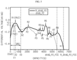
- FIG. 6 is a diagram schematically showing a first reference capacity profile (R_dQdV_P1) and a first differential capacity profile (dQdV_P1) according to an embodiment of the present disclosure.
- FIG. 6 is a diagram illustrating a first reference capacity profile (R_dQdV_P1) for a reference cell (e.g., the battery B in a BoL state) and a first differential capacity profile (dQdV_P1) for a battery B in which available lithium is lost.
- R_dQdV_P1 first reference capacity profile
- dQdV_P1 first differential capacity profile
- FIG. 6 is an enlarged view in which the upper side is the first reference capacity profile (R_dQdV_P1) and the first differential capacity profile (dQdV_P1) for the entire voltage range and the lower side is the first reference capacity profile (R_dQdV_P1) and the first differential capacity profile (dQdV_P1) for the target voltage range.
- the profile generating unit 110 may generate a first differential capacity profile (dQdV_P1) representing a correspondence between the voltage of the battery B and the differential capacity.
- the control unit 120 may be configured to determine a target capacity peak in a preset target voltage range (VR) of the received differential profile.
- VR target voltage range
- control unit 120 may be configured to set a voltage range from a preset voltage to a charge end voltage preset for the battery in the entire voltage range of the differential capacity profile as a target voltage range (VR).
- VR target voltage range
- the target voltage range (VR) is a voltage range set by the control unit 120 and may be a voltage range preset to determine a target capacity peak.
- the control unit 120 may be configured to set a voltage range from a preset voltage to a charge end voltage preset for the battery B as the target voltage range (VR).
- the charge end voltage preset for the battery B may be 4.2 [V].
- the voltage preset by the control unit 120 may be 4.0 [V]. That is, the target voltage range (VR) may be a voltage range of 4.0 [V] or more and 4.2 [V] or less.
- control unit 120 may be configured to determine a peak included in the target voltage range of the differential capacity profile as a target capacity peak.
- a peak included in the target voltage range (VR) of the first differential capacity profile (dQdV_P1) may be determined as the target capacity peak (TQ1).
- the voltage of the target capacity peak (TQ1) may be 4.11 [V]
- the differential capacity may be 102 [mAh/V].
- the control unit 120 may be configured to set a peak included in the target voltage range of a reference capacity profile preset to correspond to the differential capacity profile as a reference capacity peak.
- control unit 120 may be configured to preset a peak included in the target voltage range (VR) as the reference capacity peak in the reference capacity profile preset to correspond to the received differential profile.
- VR target voltage range
- information on the set reference capacity peak may be provided to the control unit 120.
- the reference capacity profile may be a differential capacity profile generated in the process of charging the reference cell.
- the reference cell is a cell corresponding to the battery B, and may be a battery B in a BoL state or a cell separately manufactured to generate a reference capacity profile.
- the reference cell will be described as a battery B in a BoL state.
- the reference capacity profile may be a differential capacity profile obtained based on the voltage and capacity of the reference cell measured while the reference cell is charged at a C-rate of 1 C or less. More preferably, the reference capacity profile may be a differential capacity profile obtained based on the voltage and capacity of the reference cell measured while the reference cell is charged at a C-rate of 0.05 C.
- FIG. 7 is a diagram schematically showing a first reference capacity profile (R_dQdV_P1) according to an embodiment of the present disclosure.
- phase equilibriums may occur while the battery B is being charged.
- a first phase equilibrium peak (E1) may appear at 3.36 [V] and a second phase equilibrium peak (E2) may appear at 3.62 [V].
- a third phase equilibrium peak (E3) may appear at 3.92 [V]
- a fourth phase equilibrium peak (E4) may appear at 4.12 [V].
- the fourth phase equilibrium peak (E4) may be generated in the charge end region of 4.0 [V] or more and 4.2 [V] or less. Accordingly, the control unit 120 may set a voltage range in which the fourth phase equilibrium may occur as a target voltage range (VR). In addition, the control unit 120 may determine a peak included in the target voltage range (VR) of the differential capacity profile as a target capacity peak, and determine a peak included in the target voltage range (VR) of the reference capacity profile as a reference capacity peak.
- VR target voltage range
- the control unit 120 may determine the first target capacity peak (TQ1) in the target voltage range (VR) of the first differential capacity profile (dQdV_P1) received from the measuring unit 200. Also, the control unit 120 may determine the first reference capacity peak (RQ1) in the target voltage range (VR) of the first reference capacity profile (R_dQdV_P1). Specifically, the voltage of the first target capacity peak (TQ1) may be 4.11 [V], and the differential capacity may be 102 [mAh/V]. In addition, the voltage of the first reference capacity peak (RQ1) may be 4.12 [V], and the differential capacity may be 97 [mAh/V].
- the control unit 120 may determine whether the positive electrode capacity of the battery B is lost and whether the available lithium is lost at the same time based on the behavior change of the reference capacity peak and the target capacity peak corresponding to each other.
- the fourth phase equilibrium peak (E4) belonging to the target voltage range (VR) is a peak reflecting the state of the positive electrode. Therefore, the fourth phase equilibrium peak (E4) is used to determine the state change of the positive electrode.
- control unit 120 may determine not only whether positive electrode capacity is lost but also whether available lithium is lost based on the behavior change of the target capacity peak with respect to the reference capacity peak corresponding to the fourth phase equilibrium peak (E4).
- diagnostic item related to the positive electrode For example, among a plurality of items for diagnosing degradation of the battery B, whether positive electrode capacity is lost is a diagnostic item related to the positive electrode, and whether available lithium is lost is a diagnostic item related to the negative electrode. Additional diagnostic items include whether there is overvoltage, whether negative electrode capacity related to the negative electrode is lost, and so on.
- control unit 120 may determine not only whether the positive electrode capacity related to the positive electrode is lost but also whether the available lithium related to the negative electrode is lost by using the target capacity peak reflecting the state of the positive electrode of the battery B.
- control unit 120 may be configured to determine whether available lithium of the battery B is lost according to a result of comparing the differential capacity and voltage of the reference capacity peak with the differential capacity and voltage of the target capacity peak, respectively.
- control unit 120 may be configured to determine that available lithium of the battery B is lost.
- the control unit 120 may determine whether available lithium of the battery B is lost by a result of comparing the voltages and differential capacities of the first reference capacity peak (RQ1) of the first reference capacity profile (R_dQdV_P1) and the first target peak (TQ1) of the first differential capacity profile (dQdV_P1).
- the differential capacity of the first target capacity peak (TQ1) may be 102 [mAh/V], and the voltage may be 4.11 [V].
- the differential capacity of the first reference capacity peak (RQ1) may be 97 [mAh/V], and the voltage may be 4.12 [V].
- the control unit 120 may determine that the available lithium of the battery B is lost.
- the voltage of the battery B at which the fourth phase equilibrium occurs may decrease.
- the voltage of the battery B may be a difference between the positive electrode voltage and the negative electrode voltage.
- the voltage of the battery B may be expressed by the formula "positive electrode voltage - negative electrode voltage". That is, when the available lithium of the battery B is lost, the negative electrode voltage of the battery B may increase, and when the negative electrode voltage of the battery B increases, the voltage of the battery B may decrease according to the formula "positive electrode voltage - negative electrode voltage".
- the relationship between the available lithium loss and the voltage of the battery B will be described with reference to FIG. 3 .
- the positive electrode profile when available lithium of the battery B is lost, the positive electrode profile is maintained as it is, but the negative electrode profile may be shifted to the right as a whole.
- the voltage of the battery B since the negative electrode voltage increases at the same capacity, the voltage of the battery B may decrease as a whole. That is, the voltage at which the fourth phase equilibrium occurs in the battery B where available lithium is lost may be lower than the voltage at which the fourth phase equilibrium occurs in the battery B of a BoL state.
- the voltage of the first target capacity peak (TQ1) may be lower than the voltage of the first reference capacity peak (RQ1).
- the expression capacity of the battery B may increase.
- the voltage of the battery B for the same capacity may decrease.
- the expression capacity of the battery B for the same voltage may increase. Therefore, the capacity expressed when the fourth phase equilibrium occurs in the battery B where available lithium is lost may increase compared to the capacity expressed when the fourth phase equilibrium occurs in the battery B of a BoL state.
- the expression capacity of the battery B is related to the differential capacity of the differential capacity profile. That is, in the embodiment of FIG. 6 , the differential capacity of the first target capacity peak (TQ1) for the battery B where available lithium is lost may be greater than the differential capacity of the first reference capacity peak (RQ1).
- control unit 120 may determine whether the available lithium of the battery B is lost according to the result of comparing the differential capacities and voltages between the first target capacity peak (TQ1) and the first reference capacity peak (RQ1).
- control unit 120 may be configured to determine whether the positive electrode capacity of the battery B is lost according to a result of comparing the differential capacity of the reference capacity peak with the differential capacity of the target capacity peak.
- control unit 120 may be configured to determine that the positive electrode capacity of the battery B is lost.
- the negative electrode profile is maintained as it is, but the positive electrode profile may be shifted to the left as a whole.
- the voltage of the battery B for the same capacity may increase. That is, if the positive electrode capacity is lost, the expression capacity of the battery B for the same voltage may be reduced. Therefore, the capacity expressed when the fourth phase equilibrium occurs in the battery B where the positive electrode capacity is lost may decrease compared to the capacity expressed when the fourth phase equilibrium occurs in the battery B of a BoL state.
- FIG. 8 is a diagram schematically showing a first reference capacity profile (R_dQdV_P1) and a second differential capacity profile (dQdV_P2) according to an embodiment of the present disclosure.
- FIG. 8 is a diagram illustrating the first reference capacity profile (R_dQdV_P1) for a battery B in a BoL state and the second differential capacity profile (dQdV_P2) for a battery B where positive electrode capacity is lost.
- the first reference capacity profile (R_dQdV_P1) of FIGS. 6 to 8 may be the same.
- voltages of the first reference capacity peak (RQ1) and the second target capacity peak (TQ2) may be the same as 4.12 [V].
- the differential capacity of the first reference capacity peak (RQ1) may be 97 [mAh]
- the differential capacity of the second target capacity peak (TQ2) may be 92 [mAh].
- the differential capacity (92 [V/mAh]) of the second target capacity peak (TQ2) for the battery B where positive electrode capacity is lost may be smaller than the differential capacity (97 [V/mAh]) of the first reference capacity peak (RQ1) for the battery B in a BoL state. Accordingly, in the embodiment of FIG. 8 , the control unit 120 may determine that the positive electrode capacity of the battery B is lost.
- the content of nickel included in the positive electrode material of the battery B may be 80% or more.
- the target capacity peak may be a peak appearing in the target voltage range (VR) of the differential capacity profile of the battery B containing a positive electrode material where a nickel content is 80% or more.
- the battery B may include a positive electrode material where a nickel content is 80% or more, such as NCM811 or NCM91 ⁇ 21 ⁇ 2.
- N nickel (Ni)
- C cobalt (Co)
- M manganese (Mn).
- the target capacity peak corresponding to the fourth phase equilibrium peak (E4) may be clearly determined by the control unit 120.
- the target capacity peak may be a point where the instantaneous change rate of the differential capacity for the voltage is 0, the instantaneous change rate of the differential capacity for the voltage at a low voltage side is a positive number, and the instantaneous change rate of the differential capacity for the voltage at a high voltage side is a negative number.
- the target capacity peak may be a peak having a convex form.
- the fourth phase equilibrium may not occur, and even if the fourth phase equilibrium occurs, the corresponding target capacity peak may not be generated. That is, even when the fourth phase equilibrium occurs, a point where the instantaneous change rate of the differential capacity for the voltage is 0, the instantaneous change rate of the differential capacity for the voltage at a low voltage side is a positive number, and the instantaneous change rate of the differential capacity for the voltage at a high voltage side is a negative number may not be generated.
- the battery management apparatus 100 since the battery management apparatus 100 according to an embodiment of the present disclosure uses the battery B containing a positive electrode material where a nickel content is 80% or more, it is possible to clearly determine the target capacity peak in the differential capacity profile. Accordingly, the battery management apparatus 100 may more accurately determine whether the positive electrode capacity of the battery B is lost and whether the available lithium is lost.
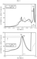
- FIG. 9 is a diagram schematically showing a second reference capacity profile (R_dQdV_P2) and a third differential capacity profile (dQdV_P3) according to an embodiment of the present disclosure.
- FIG. 9 is a diagram illustrating the second reference capacity profile (R_dQdV_P2) for a battery B in a BoL state and the third differential capacity profile (dQdV_P3) for a battery B where available lithium is lost.
- FIG. 9 is an enlarged view where the upper part is the second reference capacity profile (R_dQdV_P2) and the third differential capacity profile (dQdV_P3) for the entire voltage range, and the lower part is the second reference capacity profile (R_dQdV_P2) and the third differential capacity profile (dQdV_P3) for the target voltage range.
- the battery B may include a composite negative electrode material in which graphite and SiO are mixed.
- the ratio of graphite and SiO contained in the negative electrode material of the battery B may be graphite:SiO (9:1).
- the content of nickel contained in the positive electrode material of the battery B may be 80%.
- the battery B may include a positive electrode material where the content of nickel such as NCM811 or NCM91 ⁇ 21 ⁇ 2 is 80% or more.
- the third target capacity peak (TQ3) may be included in the target voltage range (VR).
- the control unit 120 may determine the behavior change of the third target capacity peak (TQ3) determined in the target voltage range (VR) of the third differential capacity profile (dQdV_P3) for the second reference capacity peak (RQ2) preset in the target voltage range (VR) of the second reference capacity profile (R_dQdV_P2).
- the control unit 120 may determine that the available lithium of the battery B is lost.
- control unit 120 may be configured to change at least one of an uppermost threshold value of the charging C-rate and an uppermost threshold value of the discharging C-rate preset for the battery B.
- control unit 120 may change the uppermost threshold value of the charging C-rate and the uppermost threshold value of the discharging C-rate to reduce the degradation rate of the battery B.
- control unit 120 may change each of the uppermost threshold value of the charging C-rate of the battery B and the uppermost threshold value of the discharging C-rate of the battery B to a value corresponding to 90% of a currently set value.
- the battery management apparatus 100 may change the uppermost threshold value of the charging/discharging C-rate to induce the battery B to be charged or discharged at a lower C-rate than the a currently-set charging/discharging C-rate. Accordingly, since the battery B may be charged and discharged at a lower C-rate, the degradation rate of the battery B may be slowed down.
- the battery management apparatus 100 may be provided to a battery pack 10.
- the battery pack 10 may include the battery management apparatus 100, at least one battery B, and a measuring unit 200.
- the battery pack 10 may further include electrical equipment (relays, fuses, etc.) and a case.
- the charging and discharging device 20 capable of charging and/or discharging the battery B may be connected to the battery pack 10.
- the charging and discharging device 20 may be connected to the positive electrode terminal (P+) and the negative electrode terminal (P-) of the battery pack 10.
- FIG. 10 is a diagram schematically showing a battery management method according to another embodiment of the present disclosure.
- Each step of the battery management method may be performed by the battery management apparatus 100 according to an embodiment of the present disclosure.
- content overlapping with the previously described content will be briefly described or omitted.
- the battery management method may include a battery profile obtaining step (S100), a differential profile generating step (S200), a target peak determining step (S300), and a battery state determining step (S400).
- the battery profile obtaining step (S100) is a step of obtaining a battery profile representing a correspondence between voltage and capacity of a battery B, and may be performed by the profile generating unit 110.
- the profile generating unit 110 may obtain a battery profile representing a correspondence between the voltage and capacity of the battery B from the measuring unit 200.
- the differential profile generating step (S200) is a step of generating at least one of a differential voltage profile representing a correspondence between a differential voltage for the capacity of the battery B and the capacity of the battery B and a differential voltage profile representing a correspondence between a differential capacity for the voltage of the battery B and the voltage based on the obtained battery profile, and may be performed by the profile generating unit 110.
- the profile generating unit 110 may generate a first differential voltage profile (dVdQ_P1) representing a correspondence between the capacity of the battery B and the differential voltage.
- the profile generating unit 110 may generate a second differential voltage profile (dVdQ_P2) representing a correspondence between the capacity of the battery B and the differential voltage.
- the profile generating unit 110 may generate a first differential capacity profile (dQdV_P1) representing a correspondence between the voltage of the battery B and the differential capacity.
- the profile generating unit 110 may generate a second differential capacity profile (dQdV_P2) representing a correspondence between the voltage of the battery B and the differential capacity.
- the profile generating unit 110 may generate a third differential capacity profile (dQdV_P3) representing a correspondence between the voltage of the battery B and the differential capacity.
- the target peak determining step (S300) is a step of determining a target peak included in the generated differential profile according to a rule corresponding to the type of the differential profile generated in the differential profile generating step (S200), and may be performed by the control unit 120.
- control unit 120 may determine a peak included in the target capacity range among the entire capacity region of the differential voltage profile as the target voltage peak.
- control unit 120 may receive the first differential voltage profile (dVdQ_P1) from the profile generating unit 110, and determine the first peak (P1) and the second peak (P2) included in the target capacity range (QR1) of the first differential voltage profile (dVdQ_P1) as the target voltage peak (TV1).
- control unit 120 may receive the second differential voltage profile (dVdQ_P2) from the profile generating unit 110, and determine the first peak (P1) included in the target capacity range (QR2) of the second differential voltage profile (dVdQ_P2) as the target voltage peak (TV2).
- control unit 120 when the control unit 120 receives the differential capacity profile from the profile generating unit 110, the control unit 120 may determine a peak included in the target voltage range among the entire capacity region of the differential capacity profile as the target capacity peak.
- control unit 120 may receive the first differential capacity profile (dQdV_P1) from the profile generating unit 110, and determine a peak included in the target voltage range (VR) of the first differential capacity profile (dQdV_P1) as the target capacity peak (TQ1).
- dQdV_P1 the first differential capacity profile
- VR target voltage range
- control unit 120 may receive the second differential capacity profile (dQdV_P2) from the profile generating unit 110, and determine a peak included in the target voltage range (VR) of the second differential capacity profile (dQdV_P2) as the target capacity peak (TQ2).
- dQdV_P2 the second differential capacity profile
- VR target voltage range
- control unit 120 may receive the third differential capacity profile (dQdV_P3) from the profile generating unit 110, and determine a peak included in the target voltage range (VR) of the third differential capacity profile (dQdV_P3) as the target capacity peak (TQ3).
- dQdV_P3 the third differential capacity profile
- VR target voltage range
- the battery state determining step (S400) is a step of determining the state of the battery B based on a behavior change of the target peak with respect to a reference peak preset to correspond to the type of the generated differential profile, and may be performed by the control unit 120.
- control unit 120 may determine whether the positive electrode capacity and/or the available lithium of the battery B is lost based on the behavior change of the target peak with respect to the reference peak.
- control unit 120 may determine whether the available lithium of the battery B is lost based on the number of target voltage peaks and the differential voltage of the target voltage peak.
- the control unit 120 may determine that the available lithium of the battery B is lost.
- the number of second target capacity peaks (TV2) included in the second differential voltage profile (dVdQ_P2) is one.
- the control unit 120 may determine that the available lithium of the battery B is lost.
- control unit 120 may determine whether the available lithium of the battery B is lost and/or whether the positive electrode capacity is lost based on the voltage and the differential capacity of the target capacity peak.
- the control unit 120 may determine that the available lithium of the battery B is lost.
- the control unit 120 may determine that the positive electrode capacity of the battery B is lost.
- the control unit 120 may determine that the available lithium of the battery B is lost.
- the embodiments of the present disclosure described above may not be implemented only through an apparatus and a method, but may be implemented through a program that realizes a function corresponding to the configuration of the embodiments of the present disclosure or a recording medium on which the program is recorded.
- the program or recording medium may be easily implemented by those skilled in the art from the above description of the embodiments.
Landscapes
- General Physics & Mathematics (AREA)
- Physics & Mathematics (AREA)
- Engineering & Computer Science (AREA)
- Chemical & Material Sciences (AREA)
- Chemical Kinetics & Catalysis (AREA)
- Electrochemistry (AREA)
- General Chemical & Material Sciences (AREA)
- Manufacturing & Machinery (AREA)
- Microelectronics & Electronic Packaging (AREA)
- Inorganic Chemistry (AREA)
- Secondary Cells (AREA)
- Charge And Discharge Circuits For Batteries Or The Like (AREA)
- Tests Of Electric Status Of Batteries (AREA)
Claims (13)
- Batterieverwaltungsvorrichtung (100), umfassend:eine Profilerzeugungseinheit (110), welche dazu eingerichtet ist, ein Batterieprofil zu erhalten, welches eine Entsprechung zwischen einer Spannung und einer Kapazität einer Batterie (B) repräsentiert, und ein Differenzprofil zu erzeugen, welches eine Entsprechung zwischen einer Differenzspannung für die Kapazität der Batterie (B) und der Kapazität oder eine Entsprechung zwischen einer Differenzkapazität für die Spannung der Batterie (B) und der Spannung repräsentiert, auf Grundlage des erhaltenen Batterieprofils; undeine Steuereinheit (120), welche dazu eingerichtet ist, das erzeugte Differenzprofil von der Profilerzeugungseinheit (110) zu erhalten, einen Ziel-Peak, welcher in dem empfangenen Differenzprofil umfasst ist, gemäß einer Regel zu bestimmen, welche einem Typ des empfangenen Differenzprofils entspricht, und einen Zustand der Batterie (B) auf Grundlage einer Verhaltensänderung des Ziel-Peaks mit Bezug auf einen Referenz-Peak zu bestimmen, welcher voreingestellt ist, um dem Typ des empfangenen Differenzprofils zu entsprechen,wobei die Steuereinheit (120) eingerichtet ist zum:
Bestimmen, ob ein verfügbares Lithium der Batterie (B) verloren ist, auf Grundlage der Verhaltensänderung des Ziel-Peaks mit Bezug auf den Referenz-Peak, wenn das empfangene Differenzprofil ein Differenzspannungsprofil ist, welches die Entsprechung zwischen der Differenzspannung und der Kapazität repräsentiert, durch:Festlegen eines Zielkapazitätsbereichs auf Grundlage einer Kapazität eines Referenzspannungs-Peaks, welcher dem Differenzspannungsprofil in einem gesamten Kapazitätsbereich des Differenzspannungsprofils entspricht, Bestimmen eines Peaks, welcher in dem Zielkapazitätsbereich des Differenzspannungsprofils umfasst ist, als einen Zielspannungs-Peak, und Bestimmen, ob das verfügbare Lithium verloren ist, auf Grundlage des Referenzspannungs-Peaks und des Zielspannungs-Peaks;wobei der Referenzspannungs-Peak dazu eingerichtet ist, als ein Peak voreingestellt zu sein, dessen entsprechende Kapazität eine geringste in einem Referenzspannungsprofil ist, welches voreingestellt ist, um dem Differenzspannungsprofil zu entsprechen. - Batterieverwaltungsvorrichtung nach Anspruch 1,
wobei die Steuereinheit eingerichtet ist zum:
Bestimmen, wenigstens eines davon, ob eine Kapazität einer positiven Elektrode der Batterie verloren ist und ob das verfügbare Lithium der Batterie verloren ist, auf Grundlage der Verhaltensänderung des Ziel-Peaks mit Bezug auf den Referenz-Peak, wenn das empfangene Differenzprofil ein Differenzkapazitätsprofil ist, welches die Entsprechung zwischen der Differenzkapazität und der Spannung repräsentiert. - Batterieverwaltungsvorrichtung (100) nach Anspruch 1,
wobei die Steuereinheit (120) dazu eingerichtet ist, einen Kapazitätsbereich von einer Entladeendkapazität der Batterie (B) zu einer Kapazität, welche symmetrisch zu der Entladeendkapazität der Batterie (B) ist, auf Grundlage der Kapazität des Referenzspannungs-Peaks als den Zielkapazitätsbereich festzulegen. - Batterieverwaltungsvorrichtung (100) nach Anspruch 1,
wobei die Steuereinheit (120) dazu eingerichtet ist, zu bestimmen, dass ein verfügbares Lithium der Batterie (B) verloren ist, wenn die Anzahl des bestimmten Zielspannungs-Peaks eins ist und die Differenzspannung des Zielspannungs-Peaks im Vergleich zu der Differenzspannung des Referenzspannungs-Peaks abnimmt. - Batterieverwaltungsvorrichtung (100) nach Anspruch 1,
wobei die Steuereinheit (120) dazu eingerichtet ist, zu bestimmen, dass ein verfügbares Lithium der Batterie (B) verloren ist, wenn die Anzahl des bestimmten Zielspannungs-Peaks zwei oder mehr ist. - Batterieverwaltungsvorrichtung (100) nach Anspruch 2,
wobei die Steuereinheit (120) dazu eingerichtet ist, einen Spannungsbereich von einer voreingestellten Spannung zu einer Ladeentspannung, welche für die Batterie (B) festgelegt ist, in dem gesamten Spannungsbereich des Differenzkapazitätsprofils als einen Zielspannungsbereich festzulegen, einen Peak, welcher in dem Zielspannungsbereich des Differenzkapazitätsprofils umfasst ist, als einen Zielkapazitäts-Peak festzulegen, und wenigstens eines davon, ob die Kapazität einer positiven Elektrode verloren ist und ob das verfügbare Lithium verloren ist, auf Grundlage des Zielkapazitäts-Peaks und eines Referenzkapazitäts-Peaks zu bestimmen, welcher voreingestellt ist, um dem Zielkapazitäts-Peak zu entsprechen. - Batterieverwaltungsvorrichtung (100) nach Anspruch 6,
wobei die Steuereinheit (120) dazu eingerichtet ist, einen Peak, welcher in dem Zielspannungsbereich eines Referenzkapazitätsprofils umfasst ist, welches voreingestellt ist, um dem Differenzkapazitätsprofil zu entsprechen, als den Referenzkapazitäts-Peak festzulegen. - Batterieverwaltungsvorrichtung (100) nach Anspruch 7,
wobei die Steuereinheit (120) dazu eingerichtet ist, gemäß einem Ergebnis eines Vergleichens der Differenzkapazität des Referenzkapazitäts-Peaks und der Differenzkapazität des Zielkapazitäts-Peaks zu bestimmen, ob die Kapazität einer positiven Elektrode der Batterie (B) verloren ist, und gemäß einem Ergebnis eines Vergleichens der Differenzkapazität bzw. der Spannung des Referenzkapazitäts-Peaks und der Differenzkapazität bzw. der Spannung des Zielkapazitäts-Peaks zu bestimmen, ob das verfügbare Lithium der Batterie (B) verloren ist. - Batterieverwaltungsvorrichtung (100) nach Anspruch 8,
wobei die Steuereinheit (120) dazu eingerichtet ist, zu bestimmen, dass ein verfügbares Lithium der Batterie (B) verloren ist, wenn die Differenzkapazität des Zielkapazitäts-Peaks im Vergleich zu der Differenzkapazität des Referenzkapazitäts-Peaks zunimmt und die Spannung des Zielkapazitäts-Peaks im Vergleich zu der Spannung des Referenzkapazitäts-Peaks abnimmt. - Batterieverwaltungsvorrichtung (100) nach Anspruch 8,
wobei die Steuereinheit (120) dazu eingerichtet ist, zu bestimmen, dass eine Kapazität einer positiven Elektrode der Batterie (B) verloren ist, wenn die Differenzkapazität des Zielkapazitäts-Peaks im Vergleich zu der Differenzkapazität des Referenzkapazitäts-Peaks abnimmt. - Batterieverwaltungsvorrichtung (100) nach Anspruch 1,
wobei die Steuereinheit (120) dazu eingerichtet ist, wenigstens eines aus einem Schwellenwert einer Lade-C-Rate und einem Schwellenwert einer Entlade-C-Rate, welche für die Batterie (B) voreingestellt sind, zu ändern, wenn bestimmt worden ist, dass die Kapazität einer positiven Elektrode oder das verfügbare Lithium der Batterie (B) verloren ist. - Batteriepack, umfassend die Batterieverwaltungsvorrichtung (100) nach einem der Ansprüche 1 bis 11.
- Batterieverwaltungsverfahren, umfassend:einen Batterieprofilerhaltungsschritt (S100) eines Erhaltens eines Batterieprofils, welches eine Entsprechung zwischen einer Spannung und einer Kapazität einer Batterie (B) repräsentiert;einen Differenzprofilerzeugungsschritt (S200) eines Erzeugens eines Differenzprofils, welches eine Entsprechung zwischen einer Differenzspannung für die Kapazität der Batterie (B) und der Kapazität oder eine Entsprechung zwischen einer Differenzkapazität für die Spannung der Batterie (B) und der Spannung repräsentiert, auf Grundlage des Batterieprofils, welches in dem Batterieprofilerhaltungsschritt erhalten worden ist;einen Ziel-Peak-Bestimmungsschritt (S300) eines Bestimmens eines Ziel-Peaks, welcher in dem erzeugten Differenzprofil umfasst ist, gemäß einer Regel, welche einem Typ des in dem Differenzprofilerzeugungsschritt erzeugten Differenzprofils entspricht; undeinen Batteriezustandbestimmungsschritt (S400) eines Bestimmens eines Zustands der Batterie (B) auf Grundlage einer Verhaltensänderung des Ziel-Peaks mit Bezug auf einen Referenz-Peak, welcher voreingestellt ist, um dem Typ des erzeugten Referenzprofils zu entsprechen, wobei das Verfahren ferner umfasst:Bestimmen, ob ein verfügbares Lithium der Batterie (B) verloren ist, auf Grundlage der Verhaltensänderung des Ziel-Peaks mit Bezug auf den Referenz-Peak, wenn das erzeugte Referenzprofil ein Differenzspannungsprofil ist, welches die Entsprechung zwischen der Differenzspannung und der Kapazität repräsentiert, durch:Festlegen eines Zielkapazitätsbereichs auf Grundlage einer Kapazität eines Referenzspannungs-Peaks, welcher dem Differenzspannungsprofil in einem gesamten Kapazitätsbereich des Differenzspannungsprofils entspricht,Bestimmen eines Peaks, welcher in dem Zielkapazitätsbereich des Differenzspannungsprofils umfasst ist, als einen Zielspannungs-Peak, undBestimmen, ob das verfügbare Lithium verloren ist, auf Grundlage des Referenzspannungs-Peaks und des Zielspannungs-Peaks;wobei der Referenzspannungs-Peak dazu eingerichtet ist, als ein Peak voreingestellt zu sein, dessen entsprechende Kapazität eine geringste in einem Referenzspannungsprofil ist, welches voreingestellt ist, um dem Differenzspannungsprofil zu entsprechen.
Applications Claiming Priority (3)
| Application Number | Priority Date | Filing Date | Title |
|---|---|---|---|
| KR20200088355 | 2020-07-16 | ||
| KR20200091830 | 2020-07-23 | ||
| PCT/KR2021/009212 WO2022015116A1 (ko) | 2020-07-16 | 2021-07-16 | 배터리 관리 장치 및 방법 |
Publications (3)
| Publication Number | Publication Date |
|---|---|
| EP4064412A1 EP4064412A1 (de) | 2022-09-28 |
| EP4064412A4 EP4064412A4 (de) | 2023-07-19 |
| EP4064412B1 true EP4064412B1 (de) | 2025-01-22 |
Family
ID=79554892
Family Applications (1)
| Application Number | Title | Priority Date | Filing Date |
|---|---|---|---|
| EP21842626.0A Active EP4064412B1 (de) | 2020-07-16 | 2021-07-16 | Batteriemanagementvorrichtung und -verfahren |
Country Status (8)
| Country | Link |
|---|---|
| US (1) | US12469891B2 (de) |
| EP (1) | EP4064412B1 (de) |
| JP (1) | JP7293569B2 (de) |
| KR (1) | KR20220009918A (de) |
| CN (1) | CN114846673A (de) |
| ES (1) | ES3010300T3 (de) |
| HU (1) | HUE070494T2 (de) |
| WO (1) | WO2022015116A1 (de) |
Families Citing this family (17)
| Publication number | Priority date | Publication date | Assignee | Title |
|---|---|---|---|---|
| KR102600139B1 (ko) | 2022-07-11 | 2023-11-08 | 주식회사 엘지에너지솔루션 | 배터리 관리 장치 및 방법 |
| JPWO2024047499A1 (de) * | 2022-09-02 | 2024-03-07 | ||
| KR102694988B1 (ko) * | 2022-11-01 | 2024-08-12 | 주식회사 엘지에너지솔루션 | 배터리 진단 장치 및 방법 |
| US20240210478A1 (en) * | 2022-12-26 | 2024-06-27 | Lg Energy Solution, Ltd. | Apparatus and method for managing battery |
| KR102916568B1 (ko) * | 2023-01-05 | 2026-01-22 | 주식회사 엘지에너지솔루션 | 단선 검출 장치 및 이의 동작 방법 |
| US20240248140A1 (en) * | 2023-01-25 | 2024-07-25 | Lg Energy Solution, Ltd. | Apparatus and Method for Diagnosing Battery |
| KR102847774B1 (ko) * | 2023-09-04 | 2025-08-19 | 주식회사 엘지에너지솔루션 | 배터리 진단 장치, 배터리 팩, 전기 차량 및 배터리 진단 방법 |
| KR20250078072A (ko) * | 2023-11-24 | 2025-06-02 | 주식회사 엘지에너지솔루션 | 배터리 진단 장치 및 배터리 진단 방법 |
| KR20250106953A (ko) * | 2024-01-04 | 2025-07-11 | 주식회사 엘지에너지솔루션 | 배터리 관리 장치 및 방법 |
| KR20250107066A (ko) * | 2024-01-04 | 2025-07-11 | 주식회사 엘지에너지솔루션 | 배터리 관리 장치 및 방법 |
| KR102832796B1 (ko) * | 2024-01-19 | 2025-07-09 | 주식회사 엘지에너지솔루션 | 배터리 진단 장치 및 방법 |
| KR102825275B1 (ko) * | 2024-01-26 | 2025-06-24 | 주식회사 엘지에너지솔루션 | 배터리 진단 장치 및 방법 |
| KR20250118686A (ko) * | 2024-01-30 | 2025-08-06 | 주식회사 엘지에너지솔루션 | 배터리 관리 장치 및 방법 |
| WO2025165030A1 (ko) * | 2024-01-31 | 2025-08-07 | 주식회사 엘지에너지솔루션 | 배터리 진단 장치 및 방법 |
| KR102757516B1 (ko) * | 2024-02-08 | 2025-01-21 | 주식회사 엘지에너지솔루션 | 배터리 진단 장치 및 방법 |
| KR102757503B1 (ko) * | 2024-02-08 | 2025-01-21 | 주식회사 엘지에너지솔루션 | 배터리 진단 장치 및 방법 |
| KR20250150954A (ko) * | 2024-04-12 | 2025-10-21 | 주식회사 엘지에너지솔루션 | 데이터 분석 장치 및 방법 |
Family Cites Families (29)
| Publication number | Priority date | Publication date | Assignee | Title |
|---|---|---|---|---|
| JP5682955B2 (ja) * | 2010-08-04 | 2015-03-11 | Necエナジーデバイス株式会社 | リチウム二次電池の制御システム、およびリチウム二次電池の状態検出方法 |
| US8680815B2 (en) | 2010-11-01 | 2014-03-25 | GM Global Technology Operations LLC | Method and apparatus for assessing battery state of health |
| JP5315369B2 (ja) | 2011-03-01 | 2013-10-16 | 株式会社日立製作所 | リチウム二次電池の異常充電状態検出装置及び検査方法 |
| JP2013019709A (ja) | 2011-07-08 | 2013-01-31 | Toyota Motor Corp | 二次電池システム及び車両 |
| JP5940145B2 (ja) | 2012-04-20 | 2016-06-29 | 日立オートモティブシステムズ株式会社 | 二次電池システム、二次電池の劣化状態判断方法 |
| JP6347212B2 (ja) | 2012-11-28 | 2018-06-27 | 株式会社村田製作所 | 制御装置、蓄電モジュール、電動車両、電源システムおよび制御方法 |
| JP2014139897A (ja) | 2013-01-21 | 2014-07-31 | Toyota Industries Corp | 二次電池システム |
| JP2015060761A (ja) | 2013-09-19 | 2015-03-30 | 株式会社東芝 | 二次電池の劣化診断システム及び劣化診断方法 |
| FR3020142B1 (fr) | 2014-04-16 | 2016-05-13 | Renault Sa | Procede d'estimation de l'etat de sante d'une batterie |
| EP2990818B1 (de) | 2014-09-01 | 2019-11-27 | Yokogawa Electric Corporation | Sekundärbatteriekapazitätsmesssystem und sekundärbatteriekapazitätsmessverfahren |
| JP6123844B2 (ja) * | 2014-09-01 | 2017-05-10 | 横河電機株式会社 | 二次電池容量測定システム及び二次電池容量測定方法 |
| JPWO2016135913A1 (ja) * | 2015-02-26 | 2017-05-25 | 株式会社東芝 | 蓄電池、蓄電池監視方法および監視コントローラ |
| JP6638227B2 (ja) | 2015-07-10 | 2020-01-29 | 株式会社Gsユアサ | 蓄電素子劣化状態推定装置、蓄電素子劣化状態推定方法及び蓄電システム |
| US9840161B2 (en) | 2016-03-10 | 2017-12-12 | Ford Global Technologies, Llc | Circuit and method for detection of battery cell degradation events |
| JP6978723B2 (ja) | 2017-06-05 | 2021-12-08 | 三菱自動車工業株式会社 | 二次電池システム |
| KR102270870B1 (ko) | 2017-07-10 | 2021-07-01 | 주식회사 엘지에너지솔루션 | 리튬 이차전지의 회생 방법 |
| KR101930646B1 (ko) | 2017-11-22 | 2019-03-11 | 주식회사 포스코아이씨티 | 이차 미분 전압곡선을 이용한 배터리 용량 추정 장치 및 방법 |
| KR20200088355A (ko) | 2017-12-11 | 2020-07-22 | 소니 세미컨덕터 솔루션즈 가부시키가이샤 | 버틀러 매트릭스 회로, 페이즈드 어레이 안테나, 프론트엔드 모듈 및 무선 통신 단말기 |
| KR102563753B1 (ko) | 2017-12-29 | 2023-08-04 | 삼성전자주식회사 | 배터리 충전 방법 및 장치 |
| JP7141012B2 (ja) | 2018-03-13 | 2022-09-22 | 三菱自動車工業株式会社 | 二次電池システム |
| US11150307B2 (en) | 2018-04-10 | 2021-10-19 | Lg Chem, Ltd. | Apparatus and method for diagnosing battery |
| KR102349300B1 (ko) | 2018-04-10 | 2022-01-10 | 주식회사 엘지에너지솔루션 | 배터리의 전극 정보를 결정하기 위한 장치, 방법, 배터리 팩 및 전기 시스템 |
| WO2020046019A1 (ko) | 2018-08-29 | 2020-03-05 | 주식회사 엘지화학 | 배터리 관리 장치, 배터리 관리 방법, 배터리 팩 및 전기 차량 |
| KR102259415B1 (ko) | 2018-08-29 | 2021-06-01 | 주식회사 엘지에너지솔루션 | 배터리 관리 장치, 배터리 관리 방법, 배터리 팩 및 전기 차량 |
| KR102351637B1 (ko) | 2018-09-12 | 2022-01-14 | 주식회사 엘지에너지솔루션 | 배터리 관리 장치 및 방법 |
| CN110045293A (zh) | 2019-03-15 | 2019-07-23 | 天津力神电池股份有限公司 | 一种无损分析电池活性物质材料失效的方法 |
| CN110927607A (zh) * | 2019-11-22 | 2020-03-27 | 武汉理工大学 | 辨识和量化分析锂离子电池衰退机理的方法及系统 |
| CN110888079B (zh) | 2019-11-28 | 2021-04-20 | 中山大学 | 一种容量衰减分析方法、装置、电子设备和存储介质 |
| KR102382622B1 (ko) | 2020-06-10 | 2022-04-05 | 주식회사 준엔지니어링 | 판재절단용 원형톱장치 |
-
2021
- 2021-07-16 US US17/788,518 patent/US12469891B2/en active Active
- 2021-07-16 CN CN202180007447.XA patent/CN114846673A/zh active Pending
- 2021-07-16 JP JP2022530690A patent/JP7293569B2/ja active Active
- 2021-07-16 EP EP21842626.0A patent/EP4064412B1/de active Active
- 2021-07-16 WO PCT/KR2021/009212 patent/WO2022015116A1/ko not_active Ceased
- 2021-07-16 KR KR1020210093810A patent/KR20220009918A/ko active Pending
- 2021-07-16 HU HUE21842626A patent/HUE070494T2/hu unknown
- 2021-07-16 ES ES21842626T patent/ES3010300T3/es active Active
Also Published As
| Publication number | Publication date |
|---|---|
| CN114846673A (zh) | 2022-08-02 |
| ES3010300T3 (en) | 2025-04-02 |
| JP7293569B2 (ja) | 2023-06-20 |
| EP4064412A4 (de) | 2023-07-19 |
| EP4064412A1 (de) | 2022-09-28 |
| WO2022015116A1 (ko) | 2022-01-20 |
| HUE070494T2 (hu) | 2025-06-28 |
| KR20220009918A (ko) | 2022-01-25 |
| US12469891B2 (en) | 2025-11-11 |
| US20230039356A1 (en) | 2023-02-09 |
| JP2023503971A (ja) | 2023-02-01 |
Similar Documents
| Publication | Publication Date | Title |
|---|---|---|
| EP4064412B1 (de) | Batteriemanagementvorrichtung und -verfahren | |
| CN115210594B (zh) | 用于诊断电池的状态的设备及方法、电池组和车辆 | |
| US11990590B2 (en) | Battery management apparatus and method | |
| EP4063883B1 (de) | Vorrichtung und verfahren zur diagnose des zustandes einer batterie | |
| US12248024B2 (en) | Battery classification apparatus and method | |
| EP4148950B1 (de) | Batterieverwaltungsvorrichtung und -verfahren | |
| EP4198536A1 (de) | Batterieverwaltungsvorrichtung und -verfahren | |
| US12352818B2 (en) | Battery management apparatus and method | |
| EP4145589A1 (de) | Batterieklassifizierungsvorrichtung und -verfahren | |
| EP4148865A1 (de) | Batterieverwaltungsvorrichtung und -verfahren | |
| EP4131568B1 (de) | Batterieverwaltungsgerät und -verfahren | |
| EP4152020A1 (de) | Batterieverwaltungsvorrichtung und -verfahren | |
| EP4517353A1 (de) | Vorrichtung und verfahren zur batteriediagnose | |
| EP4549974A1 (de) | Batteriediagnosevorrichtung und -verfahren | |
| US20250244404A1 (en) | Apparatus and method for diagnosing battery | |
| KR102928975B1 (ko) | 배터리 관리 장치 및 방법 | |
| EP4579261A1 (de) | Batteriediagnosevorrichtung und -verfahren | |
| CN120883419A (zh) | 电池管理装置和方法 |
Legal Events
| Date | Code | Title | Description |
|---|---|---|---|
| STAA | Information on the status of an ep patent application or granted ep patent |
Free format text: STATUS: THE INTERNATIONAL PUBLICATION HAS BEEN MADE |
|
| PUAI | Public reference made under article 153(3) epc to a published international application that has entered the european phase |
Free format text: ORIGINAL CODE: 0009012 |
|
| STAA | Information on the status of an ep patent application or granted ep patent |
Free format text: STATUS: REQUEST FOR EXAMINATION WAS MADE |
|
| 17P | Request for examination filed |
Effective date: 20220621 |
|
| AK | Designated contracting states |
Kind code of ref document: A1 Designated state(s): AL AT BE BG CH CY CZ DE DK EE ES FI FR GB GR HR HU IE IS IT LI LT LU LV MC MK MT NL NO PL PT RO RS SE SI SK SM TR |
|
| A4 | Supplementary search report drawn up and despatched |
Effective date: 20230616 |
|
| RIC1 | Information provided on ipc code assigned before grant |
Ipc: H01M 4/525 20100101ALI20230612BHEP Ipc: G01R 31/396 20190101ALI20230612BHEP Ipc: G01R 19/165 20060101ALI20230612BHEP Ipc: G01R 31/3835 20190101ALI20230612BHEP Ipc: H01M 10/052 20100101ALI20230612BHEP Ipc: G01R 31/382 20190101ALI20230612BHEP Ipc: G01R 31/36 20200101ALI20230612BHEP Ipc: G01R 31/367 20190101ALI20230612BHEP Ipc: H01M 10/42 20060101ALI20230612BHEP Ipc: H01M 10/44 20060101AFI20230612BHEP |
|
| DAV | Request for validation of the european patent (deleted) | ||
| DAX | Request for extension of the european patent (deleted) | ||
| REG | Reference to a national code |
Ref country code: DE Ref legal event code: R079 Ref country code: DE Ref legal event code: R079 Ref document number: 602021025218 Country of ref document: DE Free format text: PREVIOUS MAIN CLASS: H01M0010440000 Ipc: H01M0010480000 |
|
| GRAP | Despatch of communication of intention to grant a patent |
Free format text: ORIGINAL CODE: EPIDOSNIGR1 |
|
| STAA | Information on the status of an ep patent application or granted ep patent |
Free format text: STATUS: GRANT OF PATENT IS INTENDED |
|
| RIC1 | Information provided on ipc code assigned before grant |
Ipc: H01M 10/42 20060101ALI20240715BHEP Ipc: H01M 10/052 20100101ALI20240715BHEP Ipc: G01R 31/3835 20190101ALI20240715BHEP Ipc: G01R 31/367 20190101ALI20240715BHEP Ipc: H01M 10/48 20060101AFI20240715BHEP |
|
| INTG | Intention to grant announced |
Effective date: 20240807 |
|
| P01 | Opt-out of the competence of the unified patent court (upc) registered |
Free format text: CASE NUMBER: APP_49819/2024 Effective date: 20240903 |
|
| GRAS | Grant fee paid |
Free format text: ORIGINAL CODE: EPIDOSNIGR3 |
|
| GRAA | (expected) grant |
Free format text: ORIGINAL CODE: 0009210 |
|
| STAA | Information on the status of an ep patent application or granted ep patent |
Free format text: STATUS: THE PATENT HAS BEEN GRANTED |
|
| AK | Designated contracting states |
Kind code of ref document: B1 Designated state(s): AL AT BE BG CH CY CZ DE DK EE ES FI FR GB GR HR HU IE IS IT LI LT LU LV MC MK MT NL NO PL PT RO RS SE SI SK SM TR |
|
| REG | Reference to a national code |
Ref country code: GB Ref legal event code: FG4D |
|
| REG | Reference to a national code |
Ref country code: CH Ref legal event code: EP |
|
| REG | Reference to a national code |
Ref country code: IE Ref legal event code: FG4D |
|
| REG | Reference to a national code |
Ref country code: DE Ref legal event code: R096 Ref document number: 602021025218 Country of ref document: DE |
|
| REG | Reference to a national code |
Ref country code: ES Ref legal event code: FG2A Ref document number: 3010300 Country of ref document: ES Kind code of ref document: T3 Effective date: 20250402 |
|
| REG | Reference to a national code |
Ref country code: NL Ref legal event code: MP Effective date: 20250122 |
|
| PG25 | Lapsed in a contracting state [announced via postgrant information from national office to epo] |
Ref country code: NL Free format text: LAPSE BECAUSE OF FAILURE TO SUBMIT A TRANSLATION OF THE DESCRIPTION OR TO PAY THE FEE WITHIN THE PRESCRIBED TIME-LIMIT Effective date: 20250122 |
|
| REG | Reference to a national code |
Ref country code: HU Ref legal event code: AG4A Ref document number: E070494 Country of ref document: HU |
|
| PG25 | Lapsed in a contracting state [announced via postgrant information from national office to epo] |
Ref country code: RS Free format text: LAPSE BECAUSE OF FAILURE TO SUBMIT A TRANSLATION OF THE DESCRIPTION OR TO PAY THE FEE WITHIN THE PRESCRIBED TIME-LIMIT Effective date: 20250422 |
|
| PG25 | Lapsed in a contracting state [announced via postgrant information from national office to epo] |
Ref country code: FI Free format text: LAPSE BECAUSE OF FAILURE TO SUBMIT A TRANSLATION OF THE DESCRIPTION OR TO PAY THE FEE WITHIN THE PRESCRIBED TIME-LIMIT Effective date: 20250122 |
|
| PG25 | Lapsed in a contracting state [announced via postgrant information from national office to epo] |
Ref country code: PL Free format text: LAPSE BECAUSE OF FAILURE TO SUBMIT A TRANSLATION OF THE DESCRIPTION OR TO PAY THE FEE WITHIN THE PRESCRIBED TIME-LIMIT Effective date: 20250122 |
|
| PGFP | Annual fee paid to national office [announced via postgrant information from national office to epo] |
Ref country code: GB Payment date: 20250624 Year of fee payment: 5 |
|
| REG | Reference to a national code |
Ref country code: LT Ref legal event code: MG9D |
|
| PG25 | Lapsed in a contracting state [announced via postgrant information from national office to epo] |
Ref country code: NO Free format text: LAPSE BECAUSE OF FAILURE TO SUBMIT A TRANSLATION OF THE DESCRIPTION OR TO PAY THE FEE WITHIN THE PRESCRIBED TIME-LIMIT Effective date: 20250422 Ref country code: IS Free format text: LAPSE BECAUSE OF FAILURE TO SUBMIT A TRANSLATION OF THE DESCRIPTION OR TO PAY THE FEE WITHIN THE PRESCRIBED TIME-LIMIT Effective date: 20250522 |
|
| PGFP | Annual fee paid to national office [announced via postgrant information from national office to epo] |
Ref country code: BE Payment date: 20250425 Year of fee payment: 5 |
|
| REG | Reference to a national code |
Ref country code: AT Ref legal event code: MK05 Ref document number: 1762153 Country of ref document: AT Kind code of ref document: T Effective date: 20250122 |
|
| PG25 | Lapsed in a contracting state [announced via postgrant information from national office to epo] |
Ref country code: HR Free format text: LAPSE BECAUSE OF FAILURE TO SUBMIT A TRANSLATION OF THE DESCRIPTION OR TO PAY THE FEE WITHIN THE PRESCRIBED TIME-LIMIT Effective date: 20250122 |
|
| PG25 | Lapsed in a contracting state [announced via postgrant information from national office to epo] |
Ref country code: PT Free format text: LAPSE BECAUSE OF FAILURE TO SUBMIT A TRANSLATION OF THE DESCRIPTION OR TO PAY THE FEE WITHIN THE PRESCRIBED TIME-LIMIT Effective date: 20250522 Ref country code: LV Free format text: LAPSE BECAUSE OF FAILURE TO SUBMIT A TRANSLATION OF THE DESCRIPTION OR TO PAY THE FEE WITHIN THE PRESCRIBED TIME-LIMIT Effective date: 20250122 |
|
| PGFP | Annual fee paid to national office [announced via postgrant information from national office to epo] |
Ref country code: FR Payment date: 20250624 Year of fee payment: 5 |
|
| PG25 | Lapsed in a contracting state [announced via postgrant information from national office to epo] |
Ref country code: GR Free format text: LAPSE BECAUSE OF FAILURE TO SUBMIT A TRANSLATION OF THE DESCRIPTION OR TO PAY THE FEE WITHIN THE PRESCRIBED TIME-LIMIT Effective date: 20250423 Ref country code: BG Free format text: LAPSE BECAUSE OF FAILURE TO SUBMIT A TRANSLATION OF THE DESCRIPTION OR TO PAY THE FEE WITHIN THE PRESCRIBED TIME-LIMIT Effective date: 20250122 |
|
| PG25 | Lapsed in a contracting state [announced via postgrant information from national office to epo] |
Ref country code: AT Free format text: LAPSE BECAUSE OF FAILURE TO SUBMIT A TRANSLATION OF THE DESCRIPTION OR TO PAY THE FEE WITHIN THE PRESCRIBED TIME-LIMIT Effective date: 20250122 |
|
| PGFP | Annual fee paid to national office [announced via postgrant information from national office to epo] |
Ref country code: HU Payment date: 20250721 Year of fee payment: 5 |
|
| PG25 | Lapsed in a contracting state [announced via postgrant information from national office to epo] |
Ref country code: SE Free format text: LAPSE BECAUSE OF FAILURE TO SUBMIT A TRANSLATION OF THE DESCRIPTION OR TO PAY THE FEE WITHIN THE PRESCRIBED TIME-LIMIT Effective date: 20250122 |
|
| PG25 | Lapsed in a contracting state [announced via postgrant information from national office to epo] |
Ref country code: SM Free format text: LAPSE BECAUSE OF FAILURE TO SUBMIT A TRANSLATION OF THE DESCRIPTION OR TO PAY THE FEE WITHIN THE PRESCRIBED TIME-LIMIT Effective date: 20250122 |
|
| PGFP | Annual fee paid to national office [announced via postgrant information from national office to epo] |
Ref country code: ES Payment date: 20250822 Year of fee payment: 5 |
|
| PG25 | Lapsed in a contracting state [announced via postgrant information from national office to epo] |
Ref country code: DK Free format text: LAPSE BECAUSE OF FAILURE TO SUBMIT A TRANSLATION OF THE DESCRIPTION OR TO PAY THE FEE WITHIN THE PRESCRIBED TIME-LIMIT Effective date: 20250122 |
|
| PGFP | Annual fee paid to national office [announced via postgrant information from national office to epo] |
Ref country code: DE Payment date: 20250624 Year of fee payment: 5 |
|
| PG25 | Lapsed in a contracting state [announced via postgrant information from national office to epo] |
Ref country code: IT Free format text: LAPSE BECAUSE OF FAILURE TO SUBMIT A TRANSLATION OF THE DESCRIPTION OR TO PAY THE FEE WITHIN THE PRESCRIBED TIME-LIMIT Effective date: 20250122 |
|
| PG25 | Lapsed in a contracting state [announced via postgrant information from national office to epo] |
Ref country code: CZ Free format text: LAPSE BECAUSE OF FAILURE TO SUBMIT A TRANSLATION OF THE DESCRIPTION OR TO PAY THE FEE WITHIN THE PRESCRIBED TIME-LIMIT Effective date: 20250122 Ref country code: EE Free format text: LAPSE BECAUSE OF FAILURE TO SUBMIT A TRANSLATION OF THE DESCRIPTION OR TO PAY THE FEE WITHIN THE PRESCRIBED TIME-LIMIT Effective date: 20250122 |
|
| REG | Reference to a national code |
Ref country code: DE Ref legal event code: R097 Ref document number: 602021025218 Country of ref document: DE |
|
| PG25 | Lapsed in a contracting state [announced via postgrant information from national office to epo] |
Ref country code: RO Free format text: LAPSE BECAUSE OF FAILURE TO SUBMIT A TRANSLATION OF THE DESCRIPTION OR TO PAY THE FEE WITHIN THE PRESCRIBED TIME-LIMIT Effective date: 20250122 |
|
| PG25 | Lapsed in a contracting state [announced via postgrant information from national office to epo] |
Ref country code: SK Free format text: LAPSE BECAUSE OF FAILURE TO SUBMIT A TRANSLATION OF THE DESCRIPTION OR TO PAY THE FEE WITHIN THE PRESCRIBED TIME-LIMIT Effective date: 20250122 |
|
| PLBE | No opposition filed within time limit |
Free format text: ORIGINAL CODE: 0009261 |
|
| STAA | Information on the status of an ep patent application or granted ep patent |
Free format text: STATUS: NO OPPOSITION FILED WITHIN TIME LIMIT |
|
| 26N | No opposition filed |
Effective date: 20251023 |